EP2103531A1 - Etikettenabzieheinheit und etikettendrucker - Google Patents
Etikettenabzieheinheit und etikettendrucker Download PDFInfo
- Publication number
- EP2103531A1 EP2103531A1 EP07860293A EP07860293A EP2103531A1 EP 2103531 A1 EP2103531 A1 EP 2103531A1 EP 07860293 A EP07860293 A EP 07860293A EP 07860293 A EP07860293 A EP 07860293A EP 2103531 A1 EP2103531 A1 EP 2103531A1
- Authority
- EP
- European Patent Office
- Prior art keywords
- label
- movable body
- mount sheet
- label peeling
- peeling
- Prior art date
- Legal status (The legal status is an assumption and is not a legal conclusion. Google has not performed a legal analysis and makes no representation as to the accuracy of the status listed.)
- Granted
Links
Images


Classifications
-
- B—PERFORMING OPERATIONS; TRANSPORTING
- B65—CONVEYING; PACKING; STORING; HANDLING THIN OR FILAMENTARY MATERIAL
- B65C—LABELLING OR TAGGING MACHINES, APPARATUS, OR PROCESSES
- B65C11/00—Manually-controlled or manually-operable label dispensers, e.g. modified for the application of labels to articles
- B65C11/02—Manually-controlled or manually-operable label dispensers, e.g. modified for the application of labels to articles having printing equipment
-
- B—PERFORMING OPERATIONS; TRANSPORTING
- B41—PRINTING; LINING MACHINES; TYPEWRITERS; STAMPS
- B41J—TYPEWRITERS; SELECTIVE PRINTING MECHANISMS, i.e. MECHANISMS PRINTING OTHERWISE THAN FROM A FORME; CORRECTION OF TYPOGRAPHICAL ERRORS
- B41J11/00—Devices or arrangements of selective printing mechanisms, e.g. ink-jet printers or thermal printers, for supporting or handling copy material in sheet or web form
- B41J11/0025—Handling copy materials differing in width
-
- B—PERFORMING OPERATIONS; TRANSPORTING
- B41—PRINTING; LINING MACHINES; TYPEWRITERS; STAMPS
- B41J—TYPEWRITERS; SELECTIVE PRINTING MECHANISMS, i.e. MECHANISMS PRINTING OTHERWISE THAN FROM A FORME; CORRECTION OF TYPOGRAPHICAL ERRORS
- B41J15/00—Devices or arrangements of selective printing mechanisms, e.g. ink-jet printers or thermal printers, specially adapted for supporting or handling copy material in continuous form, e.g. webs
- B41J15/04—Supporting, feeding, or guiding devices; Mountings for web rolls or spindles
- B41J15/042—Supporting, feeding, or guiding devices; Mountings for web rolls or spindles for loading rolled-up continuous copy material into printers, e.g. for replacing a used-up paper roll; Point-of-sale printers with openable casings allowing access to the rolled-up continuous copy material
-
- B—PERFORMING OPERATIONS; TRANSPORTING
- B41—PRINTING; LINING MACHINES; TYPEWRITERS; STAMPS
- B41J—TYPEWRITERS; SELECTIVE PRINTING MECHANISMS, i.e. MECHANISMS PRINTING OTHERWISE THAN FROM A FORME; CORRECTION OF TYPOGRAPHICAL ERRORS
- B41J29/00—Details of, or accessories for, typewriters or selective printing mechanisms not otherwise provided for
- B41J29/02—Framework
-
- B—PERFORMING OPERATIONS; TRANSPORTING
- B41—PRINTING; LINING MACHINES; TYPEWRITERS; STAMPS
- B41J—TYPEWRITERS; SELECTIVE PRINTING MECHANISMS, i.e. MECHANISMS PRINTING OTHERWISE THAN FROM A FORME; CORRECTION OF TYPOGRAPHICAL ERRORS
- B41J3/00—Typewriters or selective printing or marking mechanisms characterised by the purpose for which they are constructed
- B41J3/407—Typewriters or selective printing or marking mechanisms characterised by the purpose for which they are constructed for marking on special material
- B41J3/4075—Tape printers; Label printers
-
- B—PERFORMING OPERATIONS; TRANSPORTING
- B65—CONVEYING; PACKING; STORING; HANDLING THIN OR FILAMENTARY MATERIAL
- B65C—LABELLING OR TAGGING MACHINES, APPARATUS, OR PROCESSES
- B65C9/00—Details of labelling machines or apparatus
- B65C9/0006—Removing backing sheets
-
- B—PERFORMING OPERATIONS; TRANSPORTING
- B65—CONVEYING; PACKING; STORING; HANDLING THIN OR FILAMENTARY MATERIAL
- B65H—HANDLING THIN OR FILAMENTARY MATERIAL, e.g. SHEETS, WEBS, CABLES
- B65H37/00—Article or web delivery apparatus incorporating devices for performing specified auxiliary operations
- B65H37/002—Web delivery apparatus, the web serving as support for articles, material or another web
-
- B—PERFORMING OPERATIONS; TRANSPORTING
- B65—CONVEYING; PACKING; STORING; HANDLING THIN OR FILAMENTARY MATERIAL
- B65H—HANDLING THIN OR FILAMENTARY MATERIAL, e.g. SHEETS, WEBS, CABLES
- B65H41/00—Machines for separating superposed webs
-
- B—PERFORMING OPERATIONS; TRANSPORTING
- B65—CONVEYING; PACKING; STORING; HANDLING THIN OR FILAMENTARY MATERIAL
- B65H—HANDLING THIN OR FILAMENTARY MATERIAL, e.g. SHEETS, WEBS, CABLES
- B65H2701/00—Handled material; Storage means
- B65H2701/10—Handled articles or webs
- B65H2701/19—Specific article or web
- B65H2701/194—Web supporting regularly spaced adhesive articles, e.g. labels, rubber articles, labels or stamps
-
- Y—GENERAL TAGGING OF NEW TECHNOLOGICAL DEVELOPMENTS; GENERAL TAGGING OF CROSS-SECTIONAL TECHNOLOGIES SPANNING OVER SEVERAL SECTIONS OF THE IPC; TECHNICAL SUBJECTS COVERED BY FORMER USPC CROSS-REFERENCE ART COLLECTIONS [XRACs] AND DIGESTS
- Y10—TECHNICAL SUBJECTS COVERED BY FORMER USPC
- Y10T—TECHNICAL SUBJECTS COVERED BY FORMER US CLASSIFICATION
- Y10T156/00—Adhesive bonding and miscellaneous chemical manufacture
- Y10T156/11—Methods of delaminating, per se; i.e., separating at bonding face
- Y10T156/1168—Gripping and pulling work apart during delaminating
- Y10T156/1174—Using roller for delamination [e.g., roller pairs operating at differing speeds or directions, etc.]
-
- Y—GENERAL TAGGING OF NEW TECHNOLOGICAL DEVELOPMENTS; GENERAL TAGGING OF CROSS-SECTIONAL TECHNOLOGIES SPANNING OVER SEVERAL SECTIONS OF THE IPC; TECHNICAL SUBJECTS COVERED BY FORMER USPC CROSS-REFERENCE ART COLLECTIONS [XRACs] AND DIGESTS
- Y10—TECHNICAL SUBJECTS COVERED BY FORMER USPC
- Y10T—TECHNICAL SUBJECTS COVERED BY FORMER US CLASSIFICATION
- Y10T156/00—Adhesive bonding and miscellaneous chemical manufacture
- Y10T156/11—Methods of delaminating, per se; i.e., separating at bonding face
- Y10T156/1168—Gripping and pulling work apart during delaminating
- Y10T156/1195—Delaminating from release surface
-
- Y—GENERAL TAGGING OF NEW TECHNOLOGICAL DEVELOPMENTS; GENERAL TAGGING OF CROSS-SECTIONAL TECHNOLOGIES SPANNING OVER SEVERAL SECTIONS OF THE IPC; TECHNICAL SUBJECTS COVERED BY FORMER USPC CROSS-REFERENCE ART COLLECTIONS [XRACs] AND DIGESTS
- Y10—TECHNICAL SUBJECTS COVERED BY FORMER USPC
- Y10T—TECHNICAL SUBJECTS COVERED BY FORMER US CLASSIFICATION
- Y10T156/00—Adhesive bonding and miscellaneous chemical manufacture
- Y10T156/19—Delaminating means
- Y10T156/195—Delaminating roller means
-
- Y—GENERAL TAGGING OF NEW TECHNOLOGICAL DEVELOPMENTS; GENERAL TAGGING OF CROSS-SECTIONAL TECHNOLOGIES SPANNING OVER SEVERAL SECTIONS OF THE IPC; TECHNICAL SUBJECTS COVERED BY FORMER USPC CROSS-REFERENCE ART COLLECTIONS [XRACs] AND DIGESTS
- Y10—TECHNICAL SUBJECTS COVERED BY FORMER USPC
- Y10T—TECHNICAL SUBJECTS COVERED BY FORMER US CLASSIFICATION
- Y10T156/00—Adhesive bonding and miscellaneous chemical manufacture
- Y10T156/19—Delaminating means
- Y10T156/1978—Delaminating bending means
-
- Y—GENERAL TAGGING OF NEW TECHNOLOGICAL DEVELOPMENTS; GENERAL TAGGING OF CROSS-SECTIONAL TECHNOLOGIES SPANNING OVER SEVERAL SECTIONS OF THE IPC; TECHNICAL SUBJECTS COVERED BY FORMER USPC CROSS-REFERENCE ART COLLECTIONS [XRACs] AND DIGESTS
- Y10—TECHNICAL SUBJECTS COVERED BY FORMER USPC
- Y10T—TECHNICAL SUBJECTS COVERED BY FORMER US CLASSIFICATION
- Y10T156/00—Adhesive bonding and miscellaneous chemical manufacture
- Y10T156/19—Delaminating means
- Y10T156/1994—Means for delaminating from release surface
Definitions
- the present invention relates to a label peeling unit that is fitted to a label printer or the like that conveys a continuous label strip in which labels are adhered removably on a mount sheet and performs printing on the labels, and is used for peeling the labels from the mount sheet.
- the invention also relates to a label printer to which such a label peeling unit is fitted.
- a continuous label strip (hereinafter also referred to as a "paper sheet") in which labels with a predetermined length are adhered removably to a long strip-shaped mount sheet (separator) at regular intervals, for example, is used as a print medium.
- the paper sheet is conveyed by platen rollers, and the labels are printed using a thermal head provided so as to oppose the platen rollers across the paper sheet.
- printed labels are automatically peeled off from the mount sheet using a label peeling mechanism (label peeling unit).
- Patent Document 1 a paper label peeling apparatus that can be fitted to an existing thermal printer is disclosed in Patent Document 1 shown below.
- a pressure roller, a feed roller, and a capstan roller are rotatably supported onto a frame by shafts.
- the pressure roller and the feed roller are coupled to each other by a gear, and the feed roller and the capstan roller are brought into contact with each other by an appropriate pressing force.
- a peeling part is provided so as to oppose the feed roller, and the pressure roller is in contact with a platen of the thermal printer.
- This paper label peeling apparatus makes it possible to use an existing thermal printer as a label printer. Moreover, it is described that it is possible to drive the paper label peeling apparatus without necessitating a dedicated drive source, such as a motor, or a control circuit by firmware.
- Patent Document 1 JP-A-7-132919 (p. 1, Fig. 1 )
- the invention provides, in accordance with one aspect thereof, a label peeling unit fitted to a paper sheet conveying device for conveying a continuous label strip in which labels are adhered removably on a mount sheet, and used for peeling the labels, the label peeling unit comprising: an attachment body attached to a case of the paper sheet conveying device; a movable body being movable while engaging with the attachment body, the movable body being urged by a spring, whereby it stops in a closed state or in an open state with respect to the attachment body; a label peeling body, fitted to the movable body and contacted by the mount sheet of the continuous label strip conveyed by the paper sheet conveying device so that the mount sheet is bent, to thereby peel a portion of a label from the mount sheet; and a mount sheet conveying roller, attached to the movable body freely rotatably, and rotating while being in contact with a platen roller of the paper sheet conveying device via the mount sheet, to thereby convey the
- the invention provides a label printer for conveying a continuous label strip in which labels are adhered removably to a mount sheet, and performing printing on the labels
- the label printer comprising: a case in which an enclosing unit for enclosing a continuous label strip coiled in a roll form is formed; a platen roller being rotated and driven by a motor provided in the case, to thereby convey the continuous label strip; a print head for printing on labels while sandwiching the continuous label strip between it and the platen roller; a front face cover attached openably/closably to the case; and a label peeling unit according to the invention, attached to the case within the front face cover.
- a label peeling body for peeling labels and a mount sheet conveying roller for conveying a mount sheet and discharging it outside are mounted to a movable body that is capable of parallel shifting and rotational shifting relative to an attachment body. Therefore, inserting of paper sheets is made easy in the label peeling unit.
- the label peeling unit according to the invention is used by being fitted in a label printer or the like in which a continuous label strip is conveyed and the labels are printed, or in a peeling device for conveying a continuous label strip and peeling the labels (these devices are referred to as "paper sheet conveying devices" in the present application).
- a peeling device for conveying a continuous label strip and peeling the labels (these devices are referred to as "paper sheet conveying devices" in the present application).
- Fig. 1 is a perspective view showing the outline of a label printer in which a label peeling unit according to one embodiment of the invention is fitted.
- a label printer 1 comprises a case 2, a paper sheet retaining mechanism 5 for freely rotatably retaining a paper roll in which a continuous label strip (paper sheet) is coiled in roll form, a platen roller 18 for conveying the paper sheet, a label sensor 19 for detecting the location of a label, and a front face cover 3 and an upper face cover 4 that are attached pivotably relative to the case 2, in the direction shown by the arrow.
- a peeling roller 31 for pressing the surface of a paper sheet downward is attached rotatably to the front face cover 3, and in addition, the front face cover 3 is provided with a display unit 32 such as LEDs, an operation unit33 such as operation keys, and a mount sheet discharge port 34 for discharging a mount sheet.
- a recessed portion 35 is formed in at least a portion of the front face cover 3 so that the labels can be easily removed.
- a thermal head 41 and a detection protrusion 42 are attached to the upper face cover 4, and the upper face cover 4 is provided with a transparent window 43 for confirming the condition of the paper sheets.
- the case 2 is provided with a cover-open/close lever 23 for opening/closing the upper face cover 4, and a cover-open/close sensor 24 for detecting opening/closure of the upper face cover 4.
- the cover-open/close sensor 24 includes a light-emitting element and a photodetector element. Because of blocking of light by the detection protrusion 42, it can detect that the upper face cover 4 is closed, so it is possible to prevent the printing operation from being performed when the upper face cover 4 is kept open (i.e., when the upper face cover 4 is not closed completely).
- Fig. 2 is a plan view showing the structure of the main unit side of the label printer shown in Fig. 1 .
- the paper sheet retaining mechanism 5 is installed in the paper roll enclosing recess 2a so as to retain the paper roll 20r freely rotatably.
- two paper sheet side face guides 6 for restricting the location of the paper roll 20r along the width direction (shaft direction) are provided so that the locations thereof can be varied according to the width of the paper sheet.
- a paper sheet upper face guide 6a is formed integrally with at least one of the paper sheet side face guides 6. The paper sheet upper face guide 6a prevents fluttering of the paper sheet by pressing a widthwise end portion of the continuous label strip 20 that has been pulled out from the paper roll 20r downwardly, so as to make better the detection operation of the label sensor 19 (see Fig. 1 ), disposed at an opposite location across the continuous label strip 20.
- Sliding members 11 along the widthwise direction of the paper roll 20r are provided integrally with the lower ends of the paper sheet side face guides 6, and these sliding members 11 are fitted respectively in a pair of guide grooves 12, which are formed in the bottom face of the paper roll enclosing recess 2a, freely slidably.
- the two paper sheet side face guides 6 are allowed to be capable of shifting in the directions in which they approach each other or move away from each other, while keeping the parallel condition.
- Two racks 13 are provided respectively for the two paper sheet side face guides 6, along the bottom face of the paper roll enclosing recess 2a, and a pinion 14 that meshes with these racks 13 is provided freely rotatably at a location at which the racks 13 face each other.
- a pinion 14 that meshes with these racks 13 is provided freely rotatably at a location at which the racks 13 face each other.
- a platen roller retaining portion 17 is attached to the case 2, and two platen roller bearings 18a are retained by the platen roller retaining portion 17, and the platen roller 18 is retained rotatably by these platen roller bearings 18a.
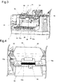
- FIG. 3 is a perspective view showing the label peeling unit in the state in which the front face cover of the label printer shown in Fig. 1 is open.
- a label peeling unit 50 has an attachment body 51 attached to the case 2 of the label printer by screw-fastening, a movable body 52 retained in such a condition as to be capable of parallel shifting and rotational shifting while engaging with the attachment body 51, a label peeling body 53 attached rotatably to the movable body 52, a mount sheet conveying roller 54 that is attached freely rotatably to the movable body 52 and is driven-rotated by making contact with the platen roller 18, which is rotation-driven by a motor that is not shown in the drawing, and a guide plate 55 located below the movable body 52 and attached freely rotatably to the attachment body 51.
- the movable body 52 By being urged by a spring, the movable body 52 can stop either in a closed state or in an open state with respect to the attachment body 51.
- the movable body 52 In Fig. 3 , the movable body 52 is in a closed state with respect to the attachment body 51.
- At least one pressing part that is pressed down when shifting the movable body 52 is provided integrally with the movable body 52.
- two pressing parts 52a are shown. By pressing down the pressing parts 52a toward the attachment body 51 side, the movable body 52 can be opened frontward.
- Fig. 4 is a view showing the state in which the front face cover and the movable body are open to insert a paper sheet.
- the mount sheet conveying roller 54 that has been in contact with the platen roller 18 can be separated from the platen roller 18, so it becomes possible to insert a paper sheet through the label peeling unit.
- the inserted continuous label strip 20 is folded over at the fore-end of the label peeling body 53 and is thereby bent considerably.
- the movable body 52 is closed by pressing the pressing part 52a toward the label printer side after inserting the paper sheet.
- the peeling roller 31 shifts above the label peeling body 53 ( Fig. 3 ) and presses the paper sheet in a direction toward the label peeling body 53 (downward) at a location opposite to the label peeling body 53.
- a label is peeled off from the mount sheet at the time when the paper sheet passes through the bent portion, and the conveying of the paper sheet is temporarily stopped in the state in which a portion of the label is removably adhered on the mount sheet and retained on the label peeling body 53.
- a peeling sensor 56 secured to the movable body 52 is used to detect whether or not the label has been removed.
- a light absorption part 52b for absorbing light is formed in the movable body 52 in order to prevent malfunctions of the peeling sensor 56 resulting from the entry of extraneous light or the irregular reflection of light.
- the next label is not issued.
- the next label is printed and conveyed to the label peeling unit 50.
- the recessed portion 35 for making removal of the label easy is formed in at least a portion of the front face cover 3. Therefore, the label can be removed easily by inserting a finger into the recessed portion 35, even if the label has a short length along the conveyance direction.
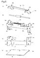
- Figs. 5(a) through 5(e) and Figs. 6(a) and (b) are perspective views showing a plurality of component parts of the label peeling unit
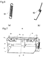
- Fig. 7 is a perspective view showing the structure of the label peeling unit assembled using the component parts.
- the attachment body 51 has a plurality of screw holes 51a formed therein and used when attached to the case of the label printer, two screw holes 51b formed therein and used for attaching the movable body 52, two engaging grooves 51c for engaging respectively with two engaging protrusions 52d (see Fig. 5(c) ) of the movable body 52, two mounting holes 51d for attaching the guide plate 55 thereto, and an engaging piece 51e for engaging with one end of an extension spring 61.
- the movable body 52 has the two pressing parts 52a on which a plurality of protruding portions are formed thereon as non-slip parts, the light absorption part 52b for absorbing light, two elongated holes 52c for attaching the movable body 52 slidably to screws (not shown) attached to the screw holes 51b of the attachment body 51, two engaging protrusions 52d protruding inwardly so as to engage respectively with the two engaging grooves 51c of the attachment body 51, shaft holes 52e for inserting the shaft of the mount sheet conveying roller 54 (see Fig. 5(b) ), and an engaging piece 52f for engaging with the other end of the extension spring 61.
- the label peeling body 53 has shaft grooves 53a formed therein for inserting the shaft of the mount sheet conveying roller 54, protruding portions 53b formed thereon, and inclined surfaces 53c formed thereon.
- the guide plate 55 has mounting pieces 55a formed thereon.
- the extension spring 61 shown in Fig. 6(a) is hooked between the engaging piece 51e of the attachment body 51 and the engaging piece 52f of the movable body 52 so as to urge the movable body 52 toward the attachment body 51 side (upward).
- a torsion spring 62 shown in Fig. 6 (b) is retained by the shaft of the mount sheet conveying roller 54, so as to urge the label peeling body 53 in a direction away from the movable body 52 (upward).
- mount screws are inserted in the screw holes 51b of the attachment body 51 through the elongated holes 52c of the movable body 52.
- the engaging protrusions 52d of the movable body 52 engage with the engaging grooves 51c of the attachment body 51.
- the movable body 52 can perform parallel shifting and rotational shifting relative to the attachment body 51.
- the engaging protrusions 52d are positioned in upper portions of the L-shaped engaging grooves 51c by the tension of the extension spring 61, and the movable body 52 is in a closed state with respect to the attachment body 51.
- the movable body 52 By pressing down the pressing parts 52a by the operator, the engaging protrusions 52d move to lower portions of the L-shaped engaging grooves 51c, the movable body 52 pivots by the tension of the extension spring 61, and the engaging protrusions 52d move to the front ends of the lower portions of the L-shaped engaging grooves 51c. Thereby, the movable body 52 opens frontward. As a result, the gap between the platen roller 18 and the mount sheet conveying roller 54 supported by the movable body 52 is widened, so inserting a paper sheet through the label peeling unit becomes easy. When the operator presses the pressing parts 52a toward the label printer side after inserting the paper sheet, the movable body 52 closes again.
- the shaft of the mount sheet conveying roller 54 is inserted through the shaft holes 52e of the movable body 52, the shaft grooves 53a of the label peeling body 53, and the torsion spring 62.
- the mount sheet conveying roller 54 is attached freely rotatably to the movable body 52
- the label peeling body 53 is attached rotatably to the movable body 52 taking the shaft of the mount sheet conveying roller 54 as the axis of rotation.
- the label peeling body 53 is urged upwardly (in the opposite direction to the moving direction of the mount sheet) by the torsion spring 62.
- the mount sheet conveying roller 54 rotates by making contact with the platen roller via a paper sheet so that it conveys the mount sheet and discharges it outside.
- both ends of the peeling roller 31 move along the inclined surfaces 53c of the label peeling body 53 and resist the upward force by the torsion spring 62.
- the protruding portions 53b of the label peeling body 53 comes into contact with the platen roller retaining portion 17 (see Fig. 3 ), so the pivoting movement by the torsion spring 62 is restricted.
- the guide plate 55 is attached freely rotatably to the attachment body 51. The guide plate 55 guides the discharged mount sheet toward the mount sheet discharge port 34 (see Fig. 1 ).
Landscapes
- Labeling Devices (AREA)
- Folding Of Thin Sheet-Like Materials, Special Discharging Devices, And Others (AREA)
- Accessory Devices And Overall Control Thereof (AREA)
Applications Claiming Priority (2)
| Application Number | Priority Date | Filing Date | Title |
|---|---|---|---|
| JP2007010159A JP4639200B2 (ja) | 2007-01-19 | 2007-01-19 | ラベル剥離ユニット及びラベルプリンタ |
| PCT/JP2007/075071 WO2008087842A1 (ja) | 2007-01-19 | 2007-12-27 | ラベル剥離ユニット及びラベルプリンタ |
Publications (3)
| Publication Number | Publication Date |
|---|---|
| EP2103531A1 true EP2103531A1 (de) | 2009-09-23 |
| EP2103531A4 EP2103531A4 (de) | 2015-03-25 |
| EP2103531B1 EP2103531B1 (de) | 2016-04-27 |
Family
ID=39635847
Family Applications (1)
| Application Number | Title | Priority Date | Filing Date |
|---|---|---|---|
| EP07860293.5A Active EP2103531B1 (de) | 2007-01-19 | 2007-12-27 | Etikettenabzieheinheit und etikettendrucker |
Country Status (4)
| Country | Link |
|---|---|
| US (1) | US8708022B2 (de) |
| EP (1) | EP2103531B1 (de) |
| JP (1) | JP4639200B2 (de) |
| WO (1) | WO2008087842A1 (de) |
Cited By (2)
| Publication number | Priority date | Publication date | Assignee | Title |
|---|---|---|---|---|
| EP3251864A4 (de) * | 2015-01-30 | 2018-05-30 | Sato Holdings Kabushiki Kaisha | Drucker |
| EP4023450A1 (de) | 2020-12-29 | 2022-07-06 | Bizerba SE & Co. KG | Etikettendrucker |
Families Citing this family (12)
| Publication number | Priority date | Publication date | Assignee | Title |
|---|---|---|---|---|
| US8786510B2 (en) | 2006-01-24 | 2014-07-22 | Avery Dennison Corporation | Radio frequency (RF) antenna containing element and methods of making the same |
| JP5733901B2 (ja) * | 2010-03-19 | 2015-06-10 | サトーホールディングス株式会社 | ラベル発行装置 |
| WO2011159727A1 (en) | 2010-06-14 | 2011-12-22 | Avery Dennison Corporation | Method, system and apparatus for making short run radio frequency identification tags and labels |
| CN103153630B (zh) * | 2010-06-24 | 2016-08-10 | 艾利丹尼森公司 | 手持便携式打印机 |
| JP6077283B2 (ja) * | 2012-03-01 | 2017-02-08 | サトーホールディングス株式会社 | サーマルプリンタ |
| JP6323637B2 (ja) * | 2013-05-24 | 2018-05-16 | ブラザー工業株式会社 | 印刷装置 |
| JP6237254B2 (ja) * | 2014-01-20 | 2017-11-29 | ブラザー工業株式会社 | 印刷物作成装置 |
| JP2018115025A (ja) * | 2017-01-20 | 2018-07-26 | 株式会社東芝 | ラベル剥離装置 |
| CN108528896B (zh) * | 2018-06-04 | 2024-03-01 | 厦门力巨自动化科技有限公司 | 片材贴标机 |
| CN111498231A (zh) * | 2019-01-30 | 2020-08-07 | 顺丰科技有限公司 | 贴标换标设备 |
| US11932027B2 (en) * | 2021-02-09 | 2024-03-19 | Zebra Technologies Corporation | Cover state sensing mechanism for media processing devices |
| JP2024139915A (ja) * | 2023-03-28 | 2024-10-10 | Fclコンポーネント株式会社 | カッタユニット、およびカッタユニットを有するプリンタ |
Family Cites Families (16)
| Publication number | Priority date | Publication date | Assignee | Title |
|---|---|---|---|---|
| US3489084A (en) * | 1967-04-25 | 1970-01-13 | Glenn L Strickland | Bed and platen printing machine with envelope feed means |
| US3631964A (en) * | 1970-07-17 | 1972-01-04 | Western Gear Corp | Conveyor system propulsion rollers with releasable drive means |
| US4498389A (en) * | 1971-12-08 | 1985-02-12 | Monarch Marking Systems, Inc. | Labeler with inking mechanism |
| US3893664A (en) * | 1973-07-20 | 1975-07-08 | Elmer R Thomsen | Stock feeder for printing press |
| US4490206A (en) * | 1984-02-28 | 1984-12-25 | Monarch Marking Systems, Inc. | Hand-held labeler |
| JPH0715381B2 (ja) | 1985-01-16 | 1995-02-22 | 日産自動車株式会社 | 操舵角度検出装置 |
| JPS61164110U (de) * | 1985-03-30 | 1986-10-11 | ||
| DE3609789A1 (de) * | 1986-03-22 | 1987-10-01 | Espera Werke Gmbh | Thermodrucker fuer auf einen traegerstreifen abloesbar angebrachte etiketten und fuer streifenmaterial |
| JPS63164407A (ja) | 1986-12-26 | 1988-07-07 | Matsushita Electric Ind Co Ltd | フライバツクトランス |
| JPS63164407U (de) * | 1987-04-14 | 1988-10-26 | ||
| JP2833978B2 (ja) | 1993-11-05 | 1998-12-09 | 甲府日本電気株式会社 | ラベル紙剥離装置 |
| US5478428A (en) * | 1994-08-01 | 1995-12-26 | Grand Rapids Label Company | Label separator and method for separating a label from a backing |
| JP3545830B2 (ja) * | 1995-04-27 | 2004-07-21 | 東芝テック株式会社 | ラベルプリンタ |
| JP3877247B2 (ja) * | 1997-07-09 | 2007-02-07 | 株式会社サトー | ラベルプリンターのラベル剥離装置 |
| US6766844B1 (en) * | 2001-10-30 | 2004-07-27 | Zih Corp. | Peel assembly for a printer |
| JP2009092996A (ja) * | 2007-10-10 | 2009-04-30 | Ricoh Co Ltd | 画像除去装置、画像除去方法、画像形成・除去システム |
-
2007
- 2007-01-19 JP JP2007010159A patent/JP4639200B2/ja active Active
- 2007-12-27 EP EP07860293.5A patent/EP2103531B1/de active Active
- 2007-12-27 US US12/523,751 patent/US8708022B2/en active Active
- 2007-12-27 WO PCT/JP2007/075071 patent/WO2008087842A1/ja not_active Ceased
Cited By (3)
| Publication number | Priority date | Publication date | Assignee | Title |
|---|---|---|---|---|
| EP3251864A4 (de) * | 2015-01-30 | 2018-05-30 | Sato Holdings Kabushiki Kaisha | Drucker |
| EP4023450A1 (de) | 2020-12-29 | 2022-07-06 | Bizerba SE & Co. KG | Etikettendrucker |
| WO2022144119A1 (de) | 2020-12-29 | 2022-07-07 | Bizerba SE & Co. KG | Etikettendrucker |
Also Published As
| Publication number | Publication date |
|---|---|
| EP2103531B1 (de) | 2016-04-27 |
| EP2103531A4 (de) | 2015-03-25 |
| WO2008087842A1 (ja) | 2008-07-24 |
| US20100089535A1 (en) | 2010-04-15 |
| US8708022B2 (en) | 2014-04-29 |
| JP2008174360A (ja) | 2008-07-31 |
| JP4639200B2 (ja) | 2011-02-23 |
Similar Documents
| Publication | Publication Date | Title |
|---|---|---|
| EP2103531B1 (de) | Etikettenabzieheinheit und etikettendrucker | |
| EP2052820B1 (de) | Drucker | |
| US8419305B2 (en) | Cutting mechanism for printing apparatus, and printing apparatus including the same | |
| EP2363292B1 (de) | Etikettenseparator und Etikettendrucker mit einem Etikettenseparator | |
| CN105050822B (zh) | 打印机 | |
| EP0872352B1 (de) | Bildaufzeichnungsgerät mit abnehmbarer Bandrollenkassette | |
| JP5141388B2 (ja) | 用紙処理装置 | |
| EP4209440B1 (de) | Drucker | |
| CN108602364B (zh) | 打印机 | |
| CN106715136A (zh) | 打印机 | |
| US6953246B2 (en) | Recording apparatus | |
| JP5908292B2 (ja) | プリンタ及びその用紙ガイド機構 | |
| US20140119805A1 (en) | Printer apparatus | |
| US20120224906A1 (en) | Printer | |
| JP6587878B2 (ja) | プリンタ装置 | |
| JP2005178309A (ja) | 印字媒体用センサー支持装置 | |
| US9604477B2 (en) | Printer | |
| JP2010013109A (ja) | 封筒用ラベル貼着機 | |
| JP6494256B2 (ja) | ラベルプリンタ | |
| EP2025522B1 (de) | Vorrichtung zur Blattverarbeitung | |
| JP2004013633A (ja) | 非接触icカード処理装置 | |
| JP2531312Y2 (ja) | カード片寄せ搬送装置 | |
| JP4946980B2 (ja) | 用紙処理装置 | |
| KR100521099B1 (ko) | 연속 출력이 가능한 영수증 인쇄 장치 | |
| JP5187029B2 (ja) | 封筒用ラベル貼着機 |
Legal Events
| Date | Code | Title | Description |
|---|---|---|---|
| PUAI | Public reference made under article 153(3) epc to a published international application that has entered the european phase |
Free format text: ORIGINAL CODE: 0009012 |
|
| 17P | Request for examination filed |
Effective date: 20090715 |
|
| AK | Designated contracting states |
Kind code of ref document: A1 Designated state(s): AT BE BG CH CY CZ DE DK EE ES FI FR GB GR HU IE IS IT LI LT LU LV MC MT NL PL PT RO SE SI SK TR |
|
| DAX | Request for extension of the european patent (deleted) | ||
| A4 | Supplementary search report drawn up and despatched |
Effective date: 20150225 |
|
| RIC1 | Information provided on ipc code assigned before grant |
Ipc: B65H 41/00 20060101ALI20150219BHEP Ipc: B41J 29/00 20060101ALI20150219BHEP Ipc: B65C 9/00 20060101ALI20150219BHEP Ipc: B65C 9/18 20060101AFI20150219BHEP |
|
| GRAP | Despatch of communication of intention to grant a patent |
Free format text: ORIGINAL CODE: EPIDOSNIGR1 |
|
| INTG | Intention to grant announced |
Effective date: 20151204 |
|
| RIN1 | Information on inventor provided before grant (corrected) |
Inventor name: HOSONO, SHINICHIRO Inventor name: KANO, KENTA |
|
| GRAS | Grant fee paid |
Free format text: ORIGINAL CODE: EPIDOSNIGR3 |
|
| RAP1 | Party data changed (applicant data changed or rights of an application transferred) |
Owner name: SATO HOLDINGS KABUSHIKI KAISHA |
|
| GRAA | (expected) grant |
Free format text: ORIGINAL CODE: 0009210 |
|
| AK | Designated contracting states |
Kind code of ref document: B1 Designated state(s): AT BE BG CH CY CZ DE DK EE ES FI FR GB GR HU IE IS IT LI LT LU LV MC MT NL PL PT RO SE SI SK TR |
|
| REG | Reference to a national code |
Ref country code: GB Ref legal event code: FG4D |
|
| REG | Reference to a national code |
Ref country code: CH Ref legal event code: EP |
|
| REG | Reference to a national code |
Ref country code: AT Ref legal event code: REF Ref document number: 794500 Country of ref document: AT Kind code of ref document: T Effective date: 20160515 |
|
| REG | Reference to a national code |
Ref country code: IE Ref legal event code: FG4D |
|
| REG | Reference to a national code |
Ref country code: DE Ref legal event code: R096 Ref document number: 602007046056 Country of ref document: DE |
|
| REG | Reference to a national code |
Ref country code: LT Ref legal event code: MG4D |
|
| REG | Reference to a national code |
Ref country code: NL Ref legal event code: MP Effective date: 20160427 |
|
| REG | Reference to a national code |
Ref country code: AT Ref legal event code: MK05 Ref document number: 794500 Country of ref document: AT Kind code of ref document: T Effective date: 20160427 |
|
| PG25 | Lapsed in a contracting state [announced via postgrant information from national office to epo] |
Ref country code: NL Free format text: LAPSE BECAUSE OF FAILURE TO SUBMIT A TRANSLATION OF THE DESCRIPTION OR TO PAY THE FEE WITHIN THE PRESCRIBED TIME-LIMIT Effective date: 20160427 |
|
| PG25 | Lapsed in a contracting state [announced via postgrant information from national office to epo] |
Ref country code: LT Free format text: LAPSE BECAUSE OF FAILURE TO SUBMIT A TRANSLATION OF THE DESCRIPTION OR TO PAY THE FEE WITHIN THE PRESCRIBED TIME-LIMIT Effective date: 20160427 Ref country code: PL Free format text: LAPSE BECAUSE OF FAILURE TO SUBMIT A TRANSLATION OF THE DESCRIPTION OR TO PAY THE FEE WITHIN THE PRESCRIBED TIME-LIMIT Effective date: 20160427 Ref country code: FI Free format text: LAPSE BECAUSE OF FAILURE TO SUBMIT A TRANSLATION OF THE DESCRIPTION OR TO PAY THE FEE WITHIN THE PRESCRIBED TIME-LIMIT Effective date: 20160427 |
|
| REG | Reference to a national code |
Ref country code: FR Ref legal event code: PLFP Year of fee payment: 10 |
|
| PG25 | Lapsed in a contracting state [announced via postgrant information from national office to epo] |
Ref country code: SE Free format text: LAPSE BECAUSE OF FAILURE TO SUBMIT A TRANSLATION OF THE DESCRIPTION OR TO PAY THE FEE WITHIN THE PRESCRIBED TIME-LIMIT Effective date: 20160427 Ref country code: ES Free format text: LAPSE BECAUSE OF FAILURE TO SUBMIT A TRANSLATION OF THE DESCRIPTION OR TO PAY THE FEE WITHIN THE PRESCRIBED TIME-LIMIT Effective date: 20160427 Ref country code: LV Free format text: LAPSE BECAUSE OF FAILURE TO SUBMIT A TRANSLATION OF THE DESCRIPTION OR TO PAY THE FEE WITHIN THE PRESCRIBED TIME-LIMIT Effective date: 20160427 Ref country code: GR Free format text: LAPSE BECAUSE OF FAILURE TO SUBMIT A TRANSLATION OF THE DESCRIPTION OR TO PAY THE FEE WITHIN THE PRESCRIBED TIME-LIMIT Effective date: 20160728 Ref country code: PT Free format text: LAPSE BECAUSE OF FAILURE TO SUBMIT A TRANSLATION OF THE DESCRIPTION OR TO PAY THE FEE WITHIN THE PRESCRIBED TIME-LIMIT Effective date: 20160829 Ref country code: AT Free format text: LAPSE BECAUSE OF FAILURE TO SUBMIT A TRANSLATION OF THE DESCRIPTION OR TO PAY THE FEE WITHIN THE PRESCRIBED TIME-LIMIT Effective date: 20160427 |
|
| PG25 | Lapsed in a contracting state [announced via postgrant information from national office to epo] |
Ref country code: IT Free format text: LAPSE BECAUSE OF FAILURE TO SUBMIT A TRANSLATION OF THE DESCRIPTION OR TO PAY THE FEE WITHIN THE PRESCRIBED TIME-LIMIT Effective date: 20160427 Ref country code: BE Free format text: LAPSE BECAUSE OF FAILURE TO SUBMIT A TRANSLATION OF THE DESCRIPTION OR TO PAY THE FEE WITHIN THE PRESCRIBED TIME-LIMIT Effective date: 20160427 |
|
| REG | Reference to a national code |
Ref country code: DE Ref legal event code: R097 Ref document number: 602007046056 Country of ref document: DE |
|
| PG25 | Lapsed in a contracting state [announced via postgrant information from national office to epo] |
Ref country code: RO Free format text: LAPSE BECAUSE OF FAILURE TO SUBMIT A TRANSLATION OF THE DESCRIPTION OR TO PAY THE FEE WITHIN THE PRESCRIBED TIME-LIMIT Effective date: 20160427 Ref country code: EE Free format text: LAPSE BECAUSE OF FAILURE TO SUBMIT A TRANSLATION OF THE DESCRIPTION OR TO PAY THE FEE WITHIN THE PRESCRIBED TIME-LIMIT Effective date: 20160427 Ref country code: CZ Free format text: LAPSE BECAUSE OF FAILURE TO SUBMIT A TRANSLATION OF THE DESCRIPTION OR TO PAY THE FEE WITHIN THE PRESCRIBED TIME-LIMIT Effective date: 20160427 Ref country code: DK Free format text: LAPSE BECAUSE OF FAILURE TO SUBMIT A TRANSLATION OF THE DESCRIPTION OR TO PAY THE FEE WITHIN THE PRESCRIBED TIME-LIMIT Effective date: 20160427 Ref country code: SK Free format text: LAPSE BECAUSE OF FAILURE TO SUBMIT A TRANSLATION OF THE DESCRIPTION OR TO PAY THE FEE WITHIN THE PRESCRIBED TIME-LIMIT Effective date: 20160427 |
|
| PLBE | No opposition filed within time limit |
Free format text: ORIGINAL CODE: 0009261 |
|
| STAA | Information on the status of an ep patent application or granted ep patent |
Free format text: STATUS: NO OPPOSITION FILED WITHIN TIME LIMIT |
|
| 26N | No opposition filed |
Effective date: 20170130 |
|
| PG25 | Lapsed in a contracting state [announced via postgrant information from national office to epo] |
Ref country code: SI Free format text: LAPSE BECAUSE OF FAILURE TO SUBMIT A TRANSLATION OF THE DESCRIPTION OR TO PAY THE FEE WITHIN THE PRESCRIBED TIME-LIMIT Effective date: 20160427 |
|
| REG | Reference to a national code |
Ref country code: CH Ref legal event code: PL |
|
| PG25 | Lapsed in a contracting state [announced via postgrant information from national office to epo] |
Ref country code: MC Free format text: LAPSE BECAUSE OF FAILURE TO SUBMIT A TRANSLATION OF THE DESCRIPTION OR TO PAY THE FEE WITHIN THE PRESCRIBED TIME-LIMIT Effective date: 20160427 |
|
| REG | Reference to a national code |
Ref country code: IE Ref legal event code: MM4A |
|
| PG25 | Lapsed in a contracting state [announced via postgrant information from national office to epo] |
Ref country code: CH Free format text: LAPSE BECAUSE OF NON-PAYMENT OF DUE FEES Effective date: 20161231 Ref country code: LI Free format text: LAPSE BECAUSE OF NON-PAYMENT OF DUE FEES Effective date: 20161231 Ref country code: LU Free format text: LAPSE BECAUSE OF NON-PAYMENT OF DUE FEES Effective date: 20161227 |
|
| REG | Reference to a national code |
Ref country code: FR Ref legal event code: PLFP Year of fee payment: 11 |
|
| PG25 | Lapsed in a contracting state [announced via postgrant information from national office to epo] |
Ref country code: IE Free format text: LAPSE BECAUSE OF NON-PAYMENT OF DUE FEES Effective date: 20161227 |
|
| PG25 | Lapsed in a contracting state [announced via postgrant information from national office to epo] |
Ref country code: HU Free format text: LAPSE BECAUSE OF FAILURE TO SUBMIT A TRANSLATION OF THE DESCRIPTION OR TO PAY THE FEE WITHIN THE PRESCRIBED TIME-LIMIT; INVALID AB INITIO Effective date: 20071227 Ref country code: CY Free format text: LAPSE BECAUSE OF FAILURE TO SUBMIT A TRANSLATION OF THE DESCRIPTION OR TO PAY THE FEE WITHIN THE PRESCRIBED TIME-LIMIT Effective date: 20160427 |
|
| PG25 | Lapsed in a contracting state [announced via postgrant information from national office to epo] |
Ref country code: TR Free format text: LAPSE BECAUSE OF FAILURE TO SUBMIT A TRANSLATION OF THE DESCRIPTION OR TO PAY THE FEE WITHIN THE PRESCRIBED TIME-LIMIT Effective date: 20160427 Ref country code: IS Free format text: LAPSE BECAUSE OF FAILURE TO SUBMIT A TRANSLATION OF THE DESCRIPTION OR TO PAY THE FEE WITHIN THE PRESCRIBED TIME-LIMIT Effective date: 20160427 |
|
| PG25 | Lapsed in a contracting state [announced via postgrant information from national office to epo] |
Ref country code: BG Free format text: LAPSE BECAUSE OF FAILURE TO SUBMIT A TRANSLATION OF THE DESCRIPTION OR TO PAY THE FEE WITHIN THE PRESCRIBED TIME-LIMIT Effective date: 20160427 |
|
| PG25 | Lapsed in a contracting state [announced via postgrant information from national office to epo] |
Ref country code: MT Free format text: LAPSE BECAUSE OF NON-PAYMENT OF DUE FEES Effective date: 20161227 |
|
| P01 | Opt-out of the competence of the unified patent court (upc) registered |
Effective date: 20230413 |
|
| PGFP | Annual fee paid to national office [announced via postgrant information from national office to epo] |
Ref country code: DE Payment date: 20241210 Year of fee payment: 18 |
|
| PGFP | Annual fee paid to national office [announced via postgrant information from national office to epo] |
Ref country code: GB Payment date: 20241224 Year of fee payment: 18 |
|
| PGFP | Annual fee paid to national office [announced via postgrant information from national office to epo] |
Ref country code: FR Payment date: 20241223 Year of fee payment: 18 |