EP2102893B1 - Lampe - Google Patents
Lampe Download PDFInfo
- Publication number
- EP2102893B1 EP2102893B1 EP07847908.6A EP07847908A EP2102893B1 EP 2102893 B1 EP2102893 B1 EP 2102893B1 EP 07847908 A EP07847908 A EP 07847908A EP 2102893 B1 EP2102893 B1 EP 2102893B1
- Authority
- EP
- European Patent Office
- Prior art keywords
- contact element
- base
- lamp
- power supply
- sealing
- Prior art date
- Legal status (The legal status is an assumption and is not a legal conclusion. Google has not performed a legal analysis and makes no representation as to the accuracy of the status listed.)
- Not-in-force
Links
- 238000003780 insertion Methods 0.000 claims description 68
- 230000037431 insertion Effects 0.000 claims description 68
- 238000007789 sealing Methods 0.000 claims description 22
- 239000004033 plastic Substances 0.000 claims description 15
- 238000001746 injection moulding Methods 0.000 claims description 10
- 238000004519 manufacturing process Methods 0.000 claims description 8
- 239000000463 material Substances 0.000 claims description 8
- 238000000034 method Methods 0.000 claims description 5
- 238000003466 welding Methods 0.000 description 6
- 230000002093 peripheral effect Effects 0.000 description 4
- 230000000694 effects Effects 0.000 description 3
- 229910052751 metal Inorganic materials 0.000 description 3
- 239000002184 metal Substances 0.000 description 3
- 230000007704 transition Effects 0.000 description 3
- ZOKXTWBITQBERF-UHFFFAOYSA-N Molybdenum Chemical compound [Mo] ZOKXTWBITQBERF-UHFFFAOYSA-N 0.000 description 2
- 229910052736 halogen Inorganic materials 0.000 description 2
- 150000002367 halogens Chemical class 0.000 description 2
- 239000000243 solution Substances 0.000 description 2
- 229920001169 thermoplastic Polymers 0.000 description 2
- 239000004416 thermosoftening plastic Substances 0.000 description 2
- VYPSYNLAJGMNEJ-UHFFFAOYSA-N Silicium dioxide Chemical compound O=[Si]=O VYPSYNLAJGMNEJ-UHFFFAOYSA-N 0.000 description 1
- 239000011248 coating agent Substances 0.000 description 1
- 238000000576 coating method Methods 0.000 description 1
- 230000007547 defect Effects 0.000 description 1
- 230000001419 dependent effect Effects 0.000 description 1
- 238000005538 encapsulation Methods 0.000 description 1
- 238000005516 engineering process Methods 0.000 description 1
- 239000011888 foil Substances 0.000 description 1
- 239000005350 fused silica glass Substances 0.000 description 1
- 239000011521 glass Substances 0.000 description 1
- 239000011440 grout Substances 0.000 description 1
- 238000002347 injection Methods 0.000 description 1
- 239000007924 injection Substances 0.000 description 1
- 239000002991 molded plastic Substances 0.000 description 1
- 229910052750 molybdenum Inorganic materials 0.000 description 1
- 239000011733 molybdenum Substances 0.000 description 1
- 238000005476 soldering Methods 0.000 description 1
Images


Classifications
-
- H—ELECTRICITY
- H01—ELECTRIC ELEMENTS
- H01R—ELECTRICALLY-CONDUCTIVE CONNECTIONS; STRUCTURAL ASSOCIATIONS OF A PLURALITY OF MUTUALLY-INSULATED ELECTRICAL CONNECTING ELEMENTS; COUPLING DEVICES; CURRENT COLLECTORS
- H01R33/00—Coupling devices specially adapted for supporting apparatus and having one part acting as a holder providing support and electrical connection via a counterpart which is structurally associated with the apparatus, e.g. lamp holders; Separate parts thereof
- H01R33/965—Dustproof, splashproof, drip-proof, waterproof, or flameproof holders
-
- H—ELECTRICITY
- H01—ELECTRIC ELEMENTS
- H01J—ELECTRIC DISCHARGE TUBES OR DISCHARGE LAMPS
- H01J5/00—Details relating to vessels or to leading-in conductors common to two or more basic types of discharge tubes or lamps
- H01J5/50—Means forming part of the tube or lamps for the purpose of providing electrical connection to it
- H01J5/54—Means forming part of the tube or lamps for the purpose of providing electrical connection to it supported by a separate part, e.g. base
- H01J5/62—Connection of wires protruding from the vessel to connectors carried by the separate part
-
- H—ELECTRICITY
- H01—ELECTRIC ELEMENTS
- H01K—ELECTRIC INCANDESCENT LAMPS
- H01K1/00—Details
- H01K1/42—Means forming part of the lamp for the purpose of providing electrical connection, or support for, the lamp
- H01K1/46—Means forming part of the lamp for the purpose of providing electrical connection, or support for, the lamp supported by a separate part, e.g. base, cap
Definitions
- the invention relates to a method for producing a base for a lamp and a lamp base.
- These conventional vehicle lamps have a translucent, one-sided sealed lamp vessel with an incandescent filament arranged therein.
- an incandescent filament arranged therein.
- an axially adjacent to an insertion of the contact element arranged insertion funnel is provided in the base for insertion of the power supply, so that the insertion funnel of the base and the insertion of the contact element form a common insertion area.
- the contact elements are used for electrical contacting of the lamp and are integrated by means of injection molding in a plastic base part of the base.
- the power supply lines of the incandescent filament are respectively inserted into the insertion bevel of the contact element and fixed by means of a welding or soldering, in particular a laser welding.
- the insertion of the contact element is sealed in such solutions during injection molding by means of a Abdichtstempels against the horrkavtician, which rests flat against the insertion, to prevent the ingress of plastic material into the insertion.
- a disadvantage of such lamps is that during injection molding in the region between the insertion funnel of the base and the insertion bevel of the contact element may result in incomplete filling of the relatively thin-walled gap, so that the insertion funnel is formed only incomplete in the base.
- the DE 20 2006 002888 U1 discloses a lamp base with a plastic base part with a bottom side facing away from the lamp vessel, which has a recess in which the second ends of the contact lugs connected to the power supply wires led out of the lamp vessel are arranged.
- the invention has for its object to provide a method for producing a socket for such a lamp, which allows an improved insertion of the power supply lines in the contact elements with minimal manufacturing effort.
- the object is achieved by a method for producing a base for a lamp, in which in a first step at least one contact element is introduced into a mold cavity of an injection molding unit in such a way that an insertion bevel of the contact element provided for a power supply of the lamp is sealed on one side with respect to the tool cavity ,
- a Abdichtstkov is introduced into the horrkavtician, which at least partially dips into the insertion of the contact element and seals against the convincedkavmaschine, the Abdichtstkov a circumferential inclined surface and an axially spaced therefrom sealing edge or a. has narrow sealing surface portion with which the sealing rests sealingly against a peripheral wall of the contact element.
- the object is achieved by a lamp base produced by such a method.
- the insertion funnel of the base is axially spaced from the insertion of the contact element, so that during the injection molding in this area reaches a complete filling and the insertion funnel is completely formed in the base.
- no interference edges are present in the transition region between the base and contact element, which prevent or make it difficult to insert the power supply lines. Should it nevertheless come to an incomplete filling in the area between the insertion funnel and insertion, the defects extend transversely to the insertion direction and do not form the insertion of the power supply obstructing interference edges.
- the insertion funnel of the base is connected to the insertion bevel of the contact element via a substantially cylindrical wall portion of the base.
- the insertion funnel, the cylindrical wall section and the insertion bevel are arranged coaxially.
- An insertion region of the insertion bevel of the contact element is radially expanded in a preferred embodiment with respect to the cylindrical portion of the insertion funnel of the base. As a result, the insertion of the power supply into the contact element is further improved.
- the contact elements preferably extend at an angle of approximately 90 ° to the direction of the power supply lines.
- As contact elements are preferably used contact springs.
- the power supply lines are welded or soldered to the contact elements.
- a laser welding method is used.
- the contact element is preferably by means of the Abdichtstempels one-sided against a horrkavmaschine Sectionally limiting inner wall sealingly pressed and the mold cavity filled with plastic material.
- plastic material in particular a thermoplastic is used.
- the sealing surface portion of the inserted into a mold cavity for encapsulation contact element has a relation to an opening angle of the insertion greater opening angle.
- the angle of the press mark substantially corresponds to the opening angle of the Abdichtstkovs so that it forms no interference edge and does not hinder the threading of the power supply.
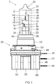
- FIG. 1 shows a front view of a designed as a halogen incandescent lamp 1, as used for example in a vehicle headlight use.
- This has a substantially cylindrical lamp vessel 2, in the interior of which 4 two filaments 6, 8 are arranged, which are used for example to produce a high beam and a daytime running light or a high beam and a low beam.
- the helical outlets 10, 12, 14, 16 of the incandescent filaments 6, 8 are each wrapped with a molybdenum foil 18 and electrically contacted via power supply wires 20, 22, 24.
- the lamp vessel 2 is sealed by a one-sided pinch 26 and inserted into a socket 28.
- the lamp vessel tip 30 facing away from the base 28 is provided with an opaque coating 32.
- the incandescent filament 6 is partially surrounded by a Abblendkappe 34 molybdenum sheet, which is supported by the power supply wire 20, which serves together with the power supply wires 22, 24 for supplying power to the two filaments 6, 8.
- the spiral outlet 10 of the incandescent filament 6 is welded by a projection welding with a welding lug 36 of the shielding cap 34 and connected via this electrically conductive to the power supply wire 20.
- the second filament outlet 12 of the filament 6 is connected to the power supply wire 24.
- the filament outlet 14 of the filament 8 is also welded to the power supply wire 24.
- the second filament outlet 16 of the filament 8 is connected to the power supply wire 22.
- the power supply wires 20, 22, 24 are fixed between two fused quartz glass webs 38 so that they are arranged in a common plane, passed through the sealed end of the lamp vessel 2 and each electrically connected to a formed as a contact lug contact element 40, 42, 44.
- the contact lugs 40, 42, 44 extend at an angle of approximately 90 ° to the direction of the power supply wires 20, 22, 24, protrude laterally from the base 28 and form the electrical connections of the halogen incandescent lamp first
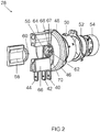
- FIG. 2 the exploded view of the base 28 from FIG. 1 shows, this has a molded plastic part as an injection molded part 46, in which the contact lugs 40, 42, 44 are embedded.
- the plastic base part 46 is followed by a spring ring 48 on the lamp vessel side and a metal sleeve 50 embedded in the plastic base part 46, which is connected to a second metal sleeve 52.
- a fixing ring 54 is fixed, which serves to hold the pinch 26 of the lamp vessel 2.
- the connected to the power supply wires 20, 22, 24 ends of the contact lugs 40, 42, 44 are arranged in a recess 56 on the underside of the plastic base part 46.
- the recess 56 can be closed by means of a closure element 58.
- a pin 60 in a receptacle 62 of the recess 58 frictionally used and causes a clamping of the closure element 58.
- This fills a gap between two opposing webs 64, 66 of the plastic base part 46 and forms with these a handling section for inserting the lamp 1 in one corresponding mounting opening of a vehicle headlamp (not shown).
- a base 28 is for example in the DE 20 2006 002 888 U1 described in more detail.
- the with the power supply wires 20, 22, 24 see FIG.
- FIG. 3 shows a sectional view of the lamp 1 in the region of the contact lugs 40, 42, 44.
- FIG. 3 is in the base 28 for inserting the power supply wires 20, 22, 24 respectively an axially spaced from the insertion bevel 70 of the contact lugs 40, 42, 44 arranged insertion funnel 72 provided with the insertion bevel 70 of the contact lugs 40, 42, 44 via an approximately cylindrical wall portion 74 of the base 28 is connected.
- the insertion funnel 72 extends from the lamp vessel 2 (see FIG. 1 ) facing the upper side of the plastic base part 46 to the cylindrical wall portion 74, wherein the insertion funnel 72, the cylindrical wall portion 74 and the insertion bevel 70 have a common longitudinal axis 76.
- An insertion region 78 of the insertion bevel 70 of the contact lugs 40, 42, 44 is radially expanded with respect to the cylindrical portion 74 of the insertion funnel 72. Thereby, the insertion of the power supply wires 20, 22, 24 in the contact lugs 40, 42, 44 is further improved. Due to the cylindrical wall section 74, a complete filling is achieved during the injection molding in the region between the insertion funnel 72 of the base 28 and the insertion bevel 70 of the contact lugs 40, 42, 44, so that the insertion funnel 72 is completely formed in the base 28.
- FIG. 4 showing a tool 80 for encapsulating a contact lug 40, 42, 44 inserted in a tool cavity 82
- the essential steps of the manufacture of the base 28 of the lamp 1 are explained below.
- the insertion ends 67 of the contact lugs 40, 42, 44 are inserted into the tool cavity 82 of the injection molding tool 80 in such a way that the power supply wires 20, 22, 24 (see FIG FIG. 3 ) of the lamp 1 provided insertion bevel 70 of the insertion end 67 is sealed on one side with respect to a tool cavity 82 bounding inner wall 84.
- a Abdichtstempel 86 is introduced into the horrkavtician 82, which at least partially dips into the insertion bevel 70 and seals against the horrkavtician 82, wherein the Abdichtstkov 86 has a circumferential inclined surface 88, which via a cylindrical portion 90 in a cf. narrow sealing surface portion 92 passes, with which the Abdichtstkov 86 sealingly abuts a peripheral wall 94 of the contact lug 40, 42, 44.
- the sealing surface section 92 preferably has a larger opening angle ⁇ than an opening angle ⁇ of the insertion bevel 72 of the contact lugs 40, 42, 44.
- the angle corresponds to a possibly resulting grout mark 96 (see FIG. 3 ) substantially the opening angle ⁇ of the Abdichtstempels 86, ie the surface of the Verpressmark ist 96 extends in extension of the cylinder portion 74 and then goes steadily into the insertion bevel 70, so that no additional peripheral edge is formed and the threading of the power supply wires 20, 22, 24 is not hindered.
- the insertion end 67 of the contact lug 40, 42, 44 is pressed by means of the Abdichtstkovs 86 on one side against the inner wall 84 of the Malawivmaschine 82 sealing.
- a plastic material is injected into the tool cavity 82 by means of an injection molding unit, not shown.
- a plastic material in particular a thermoplastic is used. Since the Abdichtstempel 86 a vgl. has narrow sealing surface portion 92, a high sealing effect is possible with a substantially reduced contact force against a flat contact.
Landscapes
- Fastening Of Light Sources Or Lamp Holders (AREA)
- Non-Portable Lighting Devices Or Systems Thereof (AREA)
- Injection Moulding Of Plastics Or The Like (AREA)
Description
- Die Erfindung betrifft ein Verfahren zur Herstellung eines Sockels für eine Lampe und einen Lampensockel.
- Eine derartig hergestellte Lampe ist beispielsweise aus der
DE 82 01 526 U1 der Anmelderin bekannt. Diese herkömmlichen Fahrzeuglampen besitzen ein lichtdurchlässiges, einseitig abgedichtetes Lampengefäß mit einer darin angeordneten Glühwendel. Zur Spannungsversorgung der Glühwendel sind deren Stromzuführungen jeweils mit einem am Lampensockel angeordneten elektrischen Kontaktelement verbunden, wobei im Sockel zum Einführen der Stromzuführungen jeweils ein axial benachbart zu einer Einführschräge des Kontaktelements angeordneter Einführtrichter vorgesehen ist, so dass der Einführtrichter des Sockels und die Einführschräge des Kontaktelements einen gemeinsamen Einführbereich ausbilden. Dadurch ist selbst bei einer ungenauen Ausrichtung der Stromzuführungen relativ zu den Kontaktelementen ein sicheres Einführen in die Kontaktelemente gewährleistet. Die Kontaktelemente dienen zur elektrischen Kontaktierung der Lampe und sind mittels Spritzgießtechnik in ein Kunststoffsockelteil des Sockels integriert. Die Stromzuführungen der Glühwendel werden jeweils in die Einführschräge des Kontaktelements eingeführt und mittels einer Schweißung oder Lötung, insbesondere einer Laserschweißung fixiert. Die Einführschräge des Kontaktelements wird bei derartigen Lösungen während des Spritzgießens mittels eines Abdichtstempels gegenüber der Werkzeugkavität abgedichtet, der flächig an der Einführschräge anliegt, um das Eindringen von Kunststoffmasse in die Einführschräge zu verhindern. Nachteilig bei derartigen Lampen ist, dass es während des Spritzgießens im Bereich zwischen dem Einführtrichter des Sockels und der Einführschräge des Kontaktelements zu einer unvollständigen Füllung des relativ dünnwandigen Zwischenraumes kommen kann, so dass der Einführtrichter im Sockel lediglich unvollständig ausgebildet wird. Dadurch sind im Übergangsbereich zwischen Sockel und Kontaktelement Störkanten vorhanden, die das Einführen der Stromzuführungen verhindern oder zumindest erheblich erschweren. Des Weiteren nachteilig bei dieser Lösung ist, dass aufgrund des flächig an der Einführschräge anliegenden konischen Abdichtstempels eine unzureichende Abdichtwirkung erreicht wird. - Die
DE 20 2006 002888 U1 offenbart einen Lampensockel mit einem Kunststoffsockelteil mit einer vom Lampengefäß abgewandten Unterseite, die eine Aussparung aufweist, in der die mit aus dem Lampengefäß herausgeführten Stromzuführungsdrähten verbundenen zweiten Enden der Kontaktfahnen angeordnet sind. - Der Erfindung liegt die Aufgabe zugrunde, ein Verfahren zur Herstellung eines Sockels für eine derartige Lampe zu schaffen, das ein verbessertes Einführen der Stromzuführungen in die Kontaktelemente bei minimalem fertigungstechnischen Aufwand ermöglicht.
- Die Aufgabe wird gelöst durch ein Verfahren zur Herstellung eines Sockels für eine Lampe, bei dem in einem ersten Arbeitsschritt zumindest ein Kontaktelement in eine Werkzeugkavität einer Spritzgießeinheit derart eingebracht wird, dass eine für eine Stromzuführung der Lampe vorgesehene Einführschräge des Kontaktelements einseitig gegenüber der Werkzeugkavität abgedichtet ist. In einem weiteren Arbeitsschritt wird ein Abdichtstempel in die Werkzeugkavität eingebracht, der zumindest abschnittsweise in die Einführschräge des Kontaktelements eintaucht und diese gegenüber der Werkzeugkavität abdichtet, wobei der Abdichtstempel eine umlaufende Schrägfläche und eine axial zu dieser beabstandete Dichtkante oder einen vgl. schmalen Dichtflächenabschnitt aufweist, mit dem der Abdichtstempel an einer Umfangswandung des Kontaktelements dichtend anliegt. Anschließend wird zum Einbetten des zumindest einen Kontaktelements in dem Sockel Kunststoffmaterial in die Werkzeugkavität eingespritzt.
- Ferner wird die Aufgabe durch einen nach einem derartigen Verfahren hergestellten Lampensockel gelöst.
- Besonders vorteilhafte Ausführungen der Erfindung sind in den abhängigen Ansprüchen beschrieben.
- Erfindungsgemäß ist der Einführtrichter des Sockels axial zu der Einführschräge des Kontaktelements beabstandet, so dass während des Spritzgießens in diesem Bereich eine vollständige Füllung erreicht und der Einführtrichter im Sockel vollständig ausgebildet wird. Dadurch sind im Übergangsbereich zwischen Sockel und Kontaktelement keine Störkanten vorhanden, die das Einführen der Stromzuführungen verhindern oder erschweren. Sollte es dennoch zu einer unvollständigen Füllung im Bereich zwischen Einführtrichter und Einführschräge kommen, erstrecken sich die Fehlstellen quer zu der Einführrichtung und bilden keine das Einführen der Stromzuführung behindernden Störkanten aus.
- Da der Abdichtstempel des Werkzeugs über eine umlaufende Dichtkante oder einen vgl. schmalen Dichtflächenabschnitt an der Umfangswandung des Kontaktelements dichtend anliegt, wird eine hohe Dichtwirkung bei gegenüber einer flächigen Anlage an der Einführschräge des Kontaktelements wesentlich verringerter Anpresskraft ermöglicht.
- Gemäß einem besonders bevorzugten Ausführungsbeispiel der Erfindung ist der Einführtrichter des Sockels mit der Einführschräge des Kontaktelements über einen im Wesentlichen zylinderförmigen Wandungsabschnitt des Sockels verbunden. Hierbei wird es besonders bevorzugt, wenn der Einführtrichter, der zylinderförmige Wandungsabschnitt und die Einführschräge koaxial angeordnet sind.
- Ein Einführbereich der Einführschräge des Kontaktelements ist bei einem bevorzugten Ausführungsbeispiel gegenüber dem zylinderförmigen Abschnitt des Einführtrichters des Sockels radial erweitert. Dadurch wird das Einführen der Stromzuführung in das Kontaktelement weiter verbessert.
- Die Kontaktelemente verlaufen vorzugsweise in einem Winkel von etwa 90° zur Richtung der Stromzuführungen. Als Kontaktelemente finden vorzugsweise Kontaktfedern Verwendung.
- Als fertigungstechnisch besonders vorteilhaft hat es sich erwiesen, wenn die Stromzuführungen mit den Kontaktelementen verschweißt oder verlötet sind. Vorzugsweise findet ein Laserschweißverfahren Verwendung.
- Bei dem Verfahren zur Herstellung eines Sockels für eine derartige Lampe wird das Kontaktelement vorzugsweise mittels des Abdichtstempels einseitig gegen eine die Werkzeugkavität abschnittsweise begrenzende Innenwandung dichtend gedrückt und die Werkzeugkavität mit Kunststoffmaterial gefüllt. Als Kunststoffmaterial wird insbesondere ein Thermoplast verwendet.
- Der Dichtflächenabschnitt des zum Umspritzen in eine Werkzeugkavität eingelegten Kontaktelements hat gemäß eines besonders bevorzugten Ausführungsbeispiels einen gegenüber einem Öffnungswinkel der Einführschräge größeren Öffnungswinkel. Dadurch entspricht der Winkel der Verpressmarkierung (Quetschkante) im Wesentlichen dem Öffnungswinkel des Abdichtstempels, so dass diese keine Störkante ausbildet und das Einfädeln der Stromzuführung nicht behindert.
- Nachstehend wird die Erfindung anhand eines bevorzugten Ausführungsbeispiels näher erläutert. Es zeigen:
-
Figur 1 eine schematische Darstellung eines bevorzugten Ausführungsbeispiels einer Lampe; -
Figur 2 eine Explosionsdarstellung des Sockels aus Figur 1; -
Figur 3 eine Schnittdarstellung des Sockels im Bereich einer der Kontaktfahnen und -
Figur 4 ein Werkzeug zum Umspritzen einer in eine Werkzeugkavität eingelegten Kontaktfahne. - Die Erfindung wird im Folgenden anhand einer einseitig gesockelten Lampe für einen Fahrzeugscheinwerfer erläutert.
-
Figur 1 zeigt eine Vorderansicht einer als Halogenglühlampe ausgebildeten Lampe 1, wie sie beispielsweise in einem Fahrzeugscheinwerfer Verwendung findet. Diese besitzt ein im Wesentlichen zylinderförmiges Lampengefäß 2, in dessen Innenraum 4 zwei Glühwendeln 6, 8 angeordnet sind, die beispielsweise zur Erzeugung eines Fernlichts und eines Tagfahrlichts oder eines Fernlichts und eines Abblendlichts verwendet werden. Die Wendelabgänge 10, 12, 14, 16 der Glühwendeln 6, 8 sind jeweils mit einer Molybdänfolie 18 umwickelt und über Stromzuführungsdrähte 20, 22, 24 elektrisch kontaktiert. Das Lampengefäß 2 ist über eine einseitige Quetschung 26 abgedichtet und in einen Sockel 28 eingesetzt. Die vom Sockel 28 abgewandte Lampengefäßkuppe 30 ist mit einer lichtundurchlässigen Beschichtung 32 versehen. Die Glühwendel 6 ist abschnittsweise von einer Abblendkappe 34 aus Molybdänblech umgeben, die von dem Stromzuführungsdraht 20 getragen wird, der zusammen mit den Stromzuführungsdrähten 22, 24 zur Energieversorgung der beiden Glühwendeln 6, 8 dient. Hierzu ist der Wendelabgang 10 der Glühwendel 6 durch eine Buckelschweißung mit einer Schweißfahne 36 der Abblendkappe 34 verschweißt und über diese elektrisch leitend mit dem Stromzuführungsdraht 20 verbunden. Der zweite Wendelabgang 12 der Glühwendel 6 ist mit dem Stromzuführungsdraht 24 verbunden. Der Wendelabgang 14 der Glühwendel 8 ist ebenfalls mit dem Stromzuführungsdraht 24 verschweißt. Der zweite Wendelabgang 16 der Glühwendel 8 ist mit dem Stromzuführungsdraht 22 verbunden. Die Stromzuführungsdrähte 20, 22, 24 sind zwischen zwei miteinander verschmolzenen Quarzglasstegen 38 fixiert, so dass sie in einer gemeinsamen Ebene angeordnet sind, durch das abgedichtete Ende des Lampengefäßes 2 hindurchgeführt und jeweils mit einem als Kontaktfahne ausgebildeten Kontaktelement 40, 42, 44 elektrisch leitend verbunden. Die Kontaktfahnen 40, 42, 44 verlaufen in einem Winkel von etwa 90° zur Richtung der Stromzuführungsdrähte 20, 22, 24, ragen seitlich aus dem Sockel 28 heraus und bilden die elektrischen Anschlüsse der Halogenglühlampe 1. - Wie
Figur 2 zu entnehmen ist, die eine Explosionsdarstellung des Sockels 28 ausFigur 1 zeigt, hat dieser ein als Spritzgussteil ausgebildetes Kunststoffsockelteil 46, in dem die Kontaktfahnen 40, 42, 44 eingebettet sind. An das Kunststoffsockelteil 46 schließt sich lampengefäßseitig ein Federring 48 und eine in das Kunststoffsockelteil 46 eingebettete Metallhülse 50 an, die mit einer zweiten Metallhülse 52 verbunden wird. An der Metallhülse 52 wird ein Fixierring 54 befestigt, der zur Halterung der Quetschung 26 des Lampengefäßes 2 dient. Die mit den Stromzuführungsdrähten 20, 22, 24 verbundenen Enden der Kontaktfahnen 40, 42, 44 sind in einer Ausnehmung 56 an der Unterseite des Kunststoffsockelteils 46 angeordnet. Die Ausnehmung 56 ist mittels eines Verschlusselements 58 verschließbar. Hierzu ist ein Zapfen 60 in eine Aufnahme 62 der Ausnehmung 58 kraftschlüssig einsetzbar und bewirkt eine Klemmung des Verschlusselements 58. Dieses füllt dabei einen Zwischenraum zweier einander gegenüberliegender Stege 64, 66 des Kunststoffsockelteils 46 und bildet mit diesen einen Handhabungsabschnitt zum Einsetzen der Lampe 1 in eine entsprechende Montageöffnung eines Fahrzeugscheinwerfers (nicht dargestellt). Ein derartiger Sockel 28 ist beispielsweise in derDE 20 2006 002 888 U1 näher beschrieben. Die mit den Stromzuführungsdrähten 20, 22, 24 (sieheFigur 1 ) zu verschweißenden Einführenden 67 der Kontaktfahnen 40, 42, 44 weisen jeweils einen Durchbruch 68 auf, durch den der entsprechende Stromzuführungsdraht 20, 22, 24 hindurchgeführt und auf der vom Lampengefäß 2 abgewandten Unterseite der Kontaktfahne 40, 42, 44 verschweißt oder verlötet wird. Vorzugsweise wird ein Laserschweißverfahren verwendet. Die Durchbrüche 68 sind jeweils mit einer Einführschräge 70 versehen, die das Einführen der Stromzuführungsdrähte 20, 22, 24 wesentlich erleichtert. Dies wird im Folgenden anhandFigur 3 näher erläutert, die eine Schnittdarstellung der Lampe 1 im Bereich der Kontaktfahnen 40, 42, 44 zeigt. - Gemäß
Figur 3 ist im Sockel 28 zum Einführen der Stromzuführungsdrähte 20, 22, 24 jeweils ein axial beabstandet zu der Einführschräge 70 der Kontaktfahnen 40, 42, 44 angeordneter Einführtrichter 72 vorgesehen, der mit der Einführschräge 70 der Kontaktfahnen 40, 42, 44 über einen etwa zylinderförmigen Wandungsabschnitt 74 des Sockels 28 verbunden ist. Der Einführtrichter 72 erstreckt sich von der dem Lampengefäß 2 (sieheFigur 1 ) zugewandten Oberseite des Kunststoffsockelteils 46 bis zu dem zylinderförmigen Wandungsabschnitt 74, wobei der Einführtrichter 72, der zylinderförmige Wandungsabschnitt 74 und die Einführschräge 70 eine gemeinsame Längsachse 76 aufweisen. Ein Einführbereich 78 der Einführschräge 70 der Kontaktfahnen 40, 42, 44 ist gegenüber dem zylinderförmigen Abschnitt 74 des Einführtrichters 72 radial erweitert. Dadurch wird das Einführen der Stromzuführungsdrähte 20, 22, 24 in die Kontaktfahnen 40, 42, 44 weiter verbessert. Aufgrund des zylinderförmigen Wandungsabschnitts 74 wird während des Spritzgießens im Bereich zwischen dem Einführtrichter 72 des Sockels 28 und der Einführschräge 70 der Kontaktfahnen 40, 42, 44 eine vollständige Füllung erreicht, so dass der Einführtrichter 72 im Sockel 28 vollständig ausgebildet wird. Dadurch sind im Übergangsbereich zwischen Sockel 28 und Einführende 67 der Kontaktfahnen 40, 42, 44 keine Störkanten vorhanden, die das Einführen der Stromzuführungsdrähte 20, 22, 24 verhindern oder erschweren. Sollte es dennoch zu einer unvollständigen Füllung im Bereich des Zylinderabschnitts 74 kommen, erstrecken sich die Fehlstellen quer zu der Einführrichtung und bilden keine das Einführen der Stromzuführungsdrähte 20, 22, 24 behindernden Störkanten aus. - Anhand
Figur 4 , die ein Werkzeug 80 zum Umspritzen einer in eine Werkzeugkavität 82 eingelegten Kontaktfahne 40, 42, 44 zeigt, werden im Folgenden die wesentlichen Schritte der Herstellung des Sockels 28 der Lampe 1 erläutert. In einem ersten Arbeitsschritt werden die Einführenden 67 der Kontaktfahnen 40, 42, 44 in die Werkzeugkavität 82 des Spritzgießwerkzeugs 80 derart eingebracht, dass die für die Stromzuführungsdrähte 20, 22, 24 (sieheFigur 3 ) der Lampe 1 vorgesehene Einführschräge 70 der Einführenden 67 einseitig gegenüber einer die Werkzeugkavität 82 begrenzenden Innenwandung 84 abgedichtet ist. Beim Schließen des Werkzeugs 80 wird ein Abdichtstempel 86 in die Werkzeugkavität 82 eingebracht, der zumindest abschnittsweise in die Einführschräge 70 eintaucht und diese gegenüber der Werkzeugkavität 82 abdichtet, wobei der Abdichtstempel 86 eine umlaufende Schrägfläche 88 aufweist, die über einen Zylinderabschnitt 90 in einen vgl. schmalen Dichtflächenabschnitt 92 übergeht, mit dem der Abdichtstempel 86 an einer Umfangswandung 94 der Kontaktfahne 40, 42, 44 dichtend anliegt. Der Dichtflächenabschnitt 92 hat vorzugsweise einen gegenüber einem Öffnungswinkel α der Einführschräge 72 der Kontaktfahnen 40, 42, 44 größeren Öffnungswinkel β. Dadurch entspricht der Winkel einer ggf. entstehenden Verpressmarkierung 96 (sieheFigur 3 ) im Wesentlichen dem Öffnungswinkel β des Abdichtstempels 86, d.h. die Fläche der Verpressmarkierung 96 verläuft in Verlängerung des Zylinderabschnitts 74 und geht dann stetig in die Einführschräge 70 über, so dass keine zusätzliche Umfangskante entsteht und das Einfädeln der Stromzuführungsdrähte 20, 22, 24 nicht behindert ist. Das Einführende 67 der Kontaktfahne 40, 42, 44 wird mittels des Abdichtstempels 86 einseitig gegen die Innenwandung 84 der Werkzeugkavität 82 dichtend gedrückt. Anschließend wird zum Einbetten des Einführendes 67 ein Kunststoffmaterial mittels einer nicht dargestellten Spritzgießeinheit in die Werkzeugkavität 82 eingespritzt. Als Kunststoffmaterial wird insbesondere ein Thermoplast verwendet. Da der Abdichtstempel 86 einen vgl. schmalen Dichtflächenabschnitt 92 hat, wird gegenüber einer flächigen Anlage eine hohe Dichtwirkung bei wesentlich verringerte Anpresskraft ermöglicht.
Claims (3)
- Verfahren zur Herstellung eines Sockels (28) für eine Lampe (1) mit den Schritten:- Einbringen zumindest eines Kontaktelements (40, 42, 44) in eine Werkzeugkavität (82) einer Spritzgießeinheit derart, dass eine für eine Stromzuführung (20, 22, 24) der Lampe (1) vorgesehene Einführschräge (70) des Kontaktelements (40, 42, 44) einseitig gegenüber der Werkzeugkavität (82) abgedichtet ist;- Einbringen eines Abdichtstempels (86) in die Werkzeugkavität (82), der zumindest abschnittsweise in die Einführschräge (70) des Kontaktelements (40, 42, 44) eintaucht und diese gegenüber der Werkzeugkavität (82) abdichtet, wobei der Abdichtstempel (86) eine umlaufende Schrägfläche (88) und eine axial zu dieser beabstandete Dichtkante oder einen vgl. schmalen Dichtflächenabschnitt (92) aufweist, mit dem der Abdichtstempel (86) an einer Umfangswandung (94) des Kontaktelements (40, 42, 44) dichtend anliegt;- Einspritzen von Kunststoffmaterial mittels der Spritzgießeinheit in die Werkzeugkavität (82) zum Einbetten des zumindest einen Kontaktelements (40, 42, 44) in dem Sockel (28).
- Verfahren nach Anspruch 1, wobei das Kontaktelement (40, 42, 44) mittels des Abdichtstempels (86) einseitig gegen eine die Werkzeugkavität (82) begrenzende Innenwandung (84) dichtend gedrückt und die Werkzeugkavität (82) mit Kunststoffmaterial gefüllt wird.
- Lampensockel hergestellt nach einem Verfahren gemäß einem der Ansprüche 1 oder 2.
Applications Claiming Priority (2)
| Application Number | Priority Date | Filing Date | Title |
|---|---|---|---|
| DE102006060027A DE102006060027A1 (de) | 2006-12-19 | 2006-12-19 | Lampe |
| PCT/EP2007/063431 WO2008074644A2 (de) | 2006-12-19 | 2007-12-06 | Lampe |
Publications (2)
| Publication Number | Publication Date |
|---|---|
| EP2102893A2 EP2102893A2 (de) | 2009-09-23 |
| EP2102893B1 true EP2102893B1 (de) | 2017-07-05 |
Family
ID=39431409
Family Applications (1)
| Application Number | Title | Priority Date | Filing Date |
|---|---|---|---|
| EP07847908.6A Not-in-force EP2102893B1 (de) | 2006-12-19 | 2007-12-06 | Lampe |
Country Status (3)
| Country | Link |
|---|---|
| EP (1) | EP2102893B1 (de) |
| DE (1) | DE102006060027A1 (de) |
| WO (1) | WO2008074644A2 (de) |
Family Cites Families (3)
| Publication number | Priority date | Publication date | Assignee | Title |
|---|---|---|---|---|
| DE3102434A1 (de) * | 1981-01-26 | 1982-08-26 | Patent-Treuhand-Gesellschaft für elektrische Glühlampen mbH, 8000 München | Elektrische gluehlampe |
| DE8522794U1 (de) * | 1985-08-07 | 1986-05-22 | Patent-Treuhand-Gesellschaft für elektrische Glühlampen mbH, 8000 München | Elektrische Lampe |
| DE202006002888U1 (de) * | 2006-02-21 | 2006-05-04 | Patent-Treuhand-Gesellschaft für elektrische Glühlampen mbH | Lampensockel und Lampe mit einem Lampensockel |
-
2006
- 2006-12-19 DE DE102006060027A patent/DE102006060027A1/de not_active Withdrawn
-
2007
- 2007-12-06 EP EP07847908.6A patent/EP2102893B1/de not_active Not-in-force
- 2007-12-06 WO PCT/EP2007/063431 patent/WO2008074644A2/de not_active Ceased
Non-Patent Citations (1)
| Title |
|---|
| None * |
Also Published As
| Publication number | Publication date |
|---|---|
| WO2008074644A3 (de) | 2009-04-02 |
| WO2008074644A2 (de) | 2008-06-26 |
| EP2102893A2 (de) | 2009-09-23 |
| DE102006060027A1 (de) | 2008-06-26 |
Similar Documents
| Publication | Publication Date | Title |
|---|---|---|
| EP1695037B1 (de) | Verfahren zur herstellung eines schaltgeräts sowie baugruppe für ein schaltgerät | |
| EP1989724B1 (de) | Lampensockel und lampe mit einem lampensockel | |
| EP1006551B1 (de) | Elektrische Lampe | |
| DE19963706A1 (de) | Beleuchtungskörper für ein medizinisches oder dentalmedizinisches Handstück | |
| DE3528399A1 (de) | Elektrische lampe | |
| DE19544012A1 (de) | Elektrische Glühlampe mit Abblendkappe und Verfahren zur Herstellung einer derartigen Lampe sowie Abblendkappe für eine elektrische Glühlampe | |
| DE19857261A1 (de) | Elektrische Entladungslampeneinrichtung und zugehöriger Isolierstopfen | |
| EP2102893B1 (de) | Lampe | |
| EP0061757B1 (de) | Verfahren zur Herstellung einer als Quetschung ausgebildeten Gefässabdichtung für eine elektrische Lampe und Quetschvorrichtung zum Durchführen des Verfahrens | |
| DE102010002650B4 (de) | Halogenglühlampe für Fahrzeugscheinwerfer | |
| EP0698474A1 (de) | Formteil aus einem thermoplastischen Kunststoff | |
| EP1859515B1 (de) | Sockel für eine lampe | |
| DE69605591T2 (de) | Lampenfassung und Verfahren zu ihrer Herstellung | |
| EP2106613B1 (de) | Lampe mit verbesserter quetschungsgeometrie | |
| DE202006009052U1 (de) | Lampensockel und Lampe mit einem Lampensockel sowie Beleuchtungssystem | |
| DE202008016865U1 (de) | Elektrische Lampe mit einem Außenkolben und einer Einbaulampe | |
| EP2122665B1 (de) | Lampensockel und lampe | |
| AT508603B1 (de) | Lampenträger für verschiedene lampentypen | |
| DE19831242A1 (de) | Kunststoffgehäuse- und Schraubsockelaufbau für kompakte Leuchtstofflampen und ihre Betriebseinheiten | |
| DE10122816B4 (de) | Stecker einer Steckverbindung | |
| WO2008074640A2 (de) | Abblendkappe mit wendel | |
| DE102006060419A1 (de) | Zweiwendellampe | |
| DE202006002886U1 (de) | Lampe | |
| DD280629A1 (de) | Verfahren zur herstellung einer hochdruck-entladungslampe fuer kfz-scheinwerfer mit abblendlicht | |
| DE3117343A1 (de) | Kraftfahrzeug-leuchte |
Legal Events
| Date | Code | Title | Description |
|---|---|---|---|
| PUAI | Public reference made under article 153(3) epc to a published international application that has entered the european phase |
Free format text: ORIGINAL CODE: 0009012 |
|
| 17P | Request for examination filed |
Effective date: 20090430 |
|
| AK | Designated contracting states |
Kind code of ref document: A2 Designated state(s): AT BE BG CH CY CZ DE DK EE ES FI FR GB GR HU IE IS IT LI LT LU LV MC MT NL PL PT RO SE SI SK TR |
|
| DAX | Request for extension of the european patent (deleted) | ||
| RAP1 | Party data changed (applicant data changed or rights of an application transferred) |
Owner name: OSRAM AG |
|
| RAP1 | Party data changed (applicant data changed or rights of an application transferred) |
Owner name: OSRAM GMBH |
|
| RAP1 | Party data changed (applicant data changed or rights of an application transferred) |
Owner name: OSRAM GMBH |
|
| 17Q | First examination report despatched |
Effective date: 20160401 |
|
| GRAP | Despatch of communication of intention to grant a patent |
Free format text: ORIGINAL CODE: EPIDOSNIGR1 |
|
| INTG | Intention to grant announced |
Effective date: 20170228 |
|
| GRAS | Grant fee paid |
Free format text: ORIGINAL CODE: EPIDOSNIGR3 |
|
| GRAA | (expected) grant |
Free format text: ORIGINAL CODE: 0009210 |
|
| AK | Designated contracting states |
Kind code of ref document: B1 Designated state(s): AT BE BG CH CY CZ DE DK EE ES FI FR GB GR HU IE IS IT LI LT LU LV MC MT NL PL PT RO SE SI SK TR |
|
| REG | Reference to a national code |
Ref country code: GB Ref legal event code: FG4D Free format text: NOT ENGLISH |
|
| REG | Reference to a national code |
Ref country code: CH Ref legal event code: EP |
|
| REG | Reference to a national code |
Ref country code: AT Ref legal event code: REF Ref document number: 907119 Country of ref document: AT Kind code of ref document: T Effective date: 20170715 |
|
| REG | Reference to a national code |
Ref country code: IE Ref legal event code: FG4D Free format text: LANGUAGE OF EP DOCUMENT: GERMAN |
|
| REG | Reference to a national code |
Ref country code: DE Ref legal event code: R096 Ref document number: 502007015740 Country of ref document: DE |
|
| REG | Reference to a national code |
Ref country code: NL Ref legal event code: MP Effective date: 20170705 |
|
| REG | Reference to a national code |
Ref country code: LT Ref legal event code: MG4D |
|
| PG25 | Lapsed in a contracting state [announced via postgrant information from national office to epo] |
Ref country code: FI Free format text: LAPSE BECAUSE OF FAILURE TO SUBMIT A TRANSLATION OF THE DESCRIPTION OR TO PAY THE FEE WITHIN THE PRESCRIBED TIME-LIMIT Effective date: 20170705 Ref country code: LT Free format text: LAPSE BECAUSE OF FAILURE TO SUBMIT A TRANSLATION OF THE DESCRIPTION OR TO PAY THE FEE WITHIN THE PRESCRIBED TIME-LIMIT Effective date: 20170705 Ref country code: SE Free format text: LAPSE BECAUSE OF FAILURE TO SUBMIT A TRANSLATION OF THE DESCRIPTION OR TO PAY THE FEE WITHIN THE PRESCRIBED TIME-LIMIT Effective date: 20170705 Ref country code: NL Free format text: LAPSE BECAUSE OF FAILURE TO SUBMIT A TRANSLATION OF THE DESCRIPTION OR TO PAY THE FEE WITHIN THE PRESCRIBED TIME-LIMIT Effective date: 20170705 |
|
| PG25 | Lapsed in a contracting state [announced via postgrant information from national office to epo] |
Ref country code: LV Free format text: LAPSE BECAUSE OF FAILURE TO SUBMIT A TRANSLATION OF THE DESCRIPTION OR TO PAY THE FEE WITHIN THE PRESCRIBED TIME-LIMIT Effective date: 20170705 Ref country code: IS Free format text: LAPSE BECAUSE OF FAILURE TO SUBMIT A TRANSLATION OF THE DESCRIPTION OR TO PAY THE FEE WITHIN THE PRESCRIBED TIME-LIMIT Effective date: 20171105 Ref country code: BG Free format text: LAPSE BECAUSE OF FAILURE TO SUBMIT A TRANSLATION OF THE DESCRIPTION OR TO PAY THE FEE WITHIN THE PRESCRIBED TIME-LIMIT Effective date: 20171005 Ref country code: PL Free format text: LAPSE BECAUSE OF FAILURE TO SUBMIT A TRANSLATION OF THE DESCRIPTION OR TO PAY THE FEE WITHIN THE PRESCRIBED TIME-LIMIT Effective date: 20170705 Ref country code: GR Free format text: LAPSE BECAUSE OF FAILURE TO SUBMIT A TRANSLATION OF THE DESCRIPTION OR TO PAY THE FEE WITHIN THE PRESCRIBED TIME-LIMIT Effective date: 20171006 Ref country code: ES Free format text: LAPSE BECAUSE OF FAILURE TO SUBMIT A TRANSLATION OF THE DESCRIPTION OR TO PAY THE FEE WITHIN THE PRESCRIBED TIME-LIMIT Effective date: 20170705 |
|
| REG | Reference to a national code |
Ref country code: DE Ref legal event code: R097 Ref document number: 502007015740 Country of ref document: DE |
|
| PG25 | Lapsed in a contracting state [announced via postgrant information from national office to epo] |
Ref country code: DK Free format text: LAPSE BECAUSE OF FAILURE TO SUBMIT A TRANSLATION OF THE DESCRIPTION OR TO PAY THE FEE WITHIN THE PRESCRIBED TIME-LIMIT Effective date: 20170705 Ref country code: CZ Free format text: LAPSE BECAUSE OF FAILURE TO SUBMIT A TRANSLATION OF THE DESCRIPTION OR TO PAY THE FEE WITHIN THE PRESCRIBED TIME-LIMIT Effective date: 20170705 Ref country code: RO Free format text: LAPSE BECAUSE OF FAILURE TO SUBMIT A TRANSLATION OF THE DESCRIPTION OR TO PAY THE FEE WITHIN THE PRESCRIBED TIME-LIMIT Effective date: 20170705 |
|
| PLBE | No opposition filed within time limit |
Free format text: ORIGINAL CODE: 0009261 |
|
| STAA | Information on the status of an ep patent application or granted ep patent |
Free format text: STATUS: NO OPPOSITION FILED WITHIN TIME LIMIT |
|
| PG25 | Lapsed in a contracting state [announced via postgrant information from national office to epo] |
Ref country code: IT Free format text: LAPSE BECAUSE OF FAILURE TO SUBMIT A TRANSLATION OF THE DESCRIPTION OR TO PAY THE FEE WITHIN THE PRESCRIBED TIME-LIMIT Effective date: 20170705 Ref country code: SK Free format text: LAPSE BECAUSE OF FAILURE TO SUBMIT A TRANSLATION OF THE DESCRIPTION OR TO PAY THE FEE WITHIN THE PRESCRIBED TIME-LIMIT Effective date: 20170705 Ref country code: EE Free format text: LAPSE BECAUSE OF FAILURE TO SUBMIT A TRANSLATION OF THE DESCRIPTION OR TO PAY THE FEE WITHIN THE PRESCRIBED TIME-LIMIT Effective date: 20170705 |
|
| 26N | No opposition filed |
Effective date: 20180406 |
|
| REG | Reference to a national code |
Ref country code: CH Ref legal event code: PL |
|
| GBPC | Gb: european patent ceased through non-payment of renewal fee |
Effective date: 20171206 |
|
| PG25 | Lapsed in a contracting state [announced via postgrant information from national office to epo] |
Ref country code: SI Free format text: LAPSE BECAUSE OF FAILURE TO SUBMIT A TRANSLATION OF THE DESCRIPTION OR TO PAY THE FEE WITHIN THE PRESCRIBED TIME-LIMIT Effective date: 20170705 |
|
| REG | Reference to a national code |
Ref country code: IE Ref legal event code: MM4A |
|
| PG25 | Lapsed in a contracting state [announced via postgrant information from national office to epo] |
Ref country code: LU Free format text: LAPSE BECAUSE OF NON-PAYMENT OF DUE FEES Effective date: 20171206 Ref country code: MT Free format text: LAPSE BECAUSE OF FAILURE TO SUBMIT A TRANSLATION OF THE DESCRIPTION OR TO PAY THE FEE WITHIN THE PRESCRIBED TIME-LIMIT Effective date: 20170705 |
|
| REG | Reference to a national code |
Ref country code: FR Ref legal event code: ST Effective date: 20180831 |
|
| REG | Reference to a national code |
Ref country code: BE Ref legal event code: MM Effective date: 20171231 |
|
| PG25 | Lapsed in a contracting state [announced via postgrant information from national office to epo] |
Ref country code: FR Free format text: LAPSE BECAUSE OF NON-PAYMENT OF DUE FEES Effective date: 20180102 Ref country code: IE Free format text: LAPSE BECAUSE OF NON-PAYMENT OF DUE FEES Effective date: 20171206 |
|
| PG25 | Lapsed in a contracting state [announced via postgrant information from national office to epo] |
Ref country code: GB Free format text: LAPSE BECAUSE OF NON-PAYMENT OF DUE FEES Effective date: 20171206 Ref country code: BE Free format text: LAPSE BECAUSE OF NON-PAYMENT OF DUE FEES Effective date: 20171231 Ref country code: LI Free format text: LAPSE BECAUSE OF NON-PAYMENT OF DUE FEES Effective date: 20171231 Ref country code: CH Free format text: LAPSE BECAUSE OF NON-PAYMENT OF DUE FEES Effective date: 20171231 |
|
| PGFP | Annual fee paid to national office [announced via postgrant information from national office to epo] |
Ref country code: DE Payment date: 20181210 Year of fee payment: 12 |
|
| REG | Reference to a national code |
Ref country code: AT Ref legal event code: MM01 Ref document number: 907119 Country of ref document: AT Kind code of ref document: T Effective date: 20171206 |
|
| PG25 | Lapsed in a contracting state [announced via postgrant information from national office to epo] |
Ref country code: AT Free format text: LAPSE BECAUSE OF NON-PAYMENT OF DUE FEES Effective date: 20171206 |
|
| PG25 | Lapsed in a contracting state [announced via postgrant information from national office to epo] |
Ref country code: MC Free format text: LAPSE BECAUSE OF FAILURE TO SUBMIT A TRANSLATION OF THE DESCRIPTION OR TO PAY THE FEE WITHIN THE PRESCRIBED TIME-LIMIT Effective date: 20170705 Ref country code: HU Free format text: LAPSE BECAUSE OF FAILURE TO SUBMIT A TRANSLATION OF THE DESCRIPTION OR TO PAY THE FEE WITHIN THE PRESCRIBED TIME-LIMIT; INVALID AB INITIO Effective date: 20071206 |
|
| PG25 | Lapsed in a contracting state [announced via postgrant information from national office to epo] |
Ref country code: CY Free format text: LAPSE BECAUSE OF NON-PAYMENT OF DUE FEES Effective date: 20170705 |
|
| PG25 | Lapsed in a contracting state [announced via postgrant information from national office to epo] |
Ref country code: TR Free format text: LAPSE BECAUSE OF FAILURE TO SUBMIT A TRANSLATION OF THE DESCRIPTION OR TO PAY THE FEE WITHIN THE PRESCRIBED TIME-LIMIT Effective date: 20170705 |
|
| PG25 | Lapsed in a contracting state [announced via postgrant information from national office to epo] |
Ref country code: PT Free format text: LAPSE BECAUSE OF FAILURE TO SUBMIT A TRANSLATION OF THE DESCRIPTION OR TO PAY THE FEE WITHIN THE PRESCRIBED TIME-LIMIT Effective date: 20170705 |
|
| REG | Reference to a national code |
Ref country code: DE Ref legal event code: R119 Ref document number: 502007015740 Country of ref document: DE |
|
| PG25 | Lapsed in a contracting state [announced via postgrant information from national office to epo] |
Ref country code: DE Free format text: LAPSE BECAUSE OF NON-PAYMENT OF DUE FEES Effective date: 20200701 |