EP2093626B1 - Entwicklungsvorrichtung - Google Patents
Entwicklungsvorrichtung Download PDFInfo
- Publication number
- EP2093626B1 EP2093626B1 EP09152577.4A EP09152577A EP2093626B1 EP 2093626 B1 EP2093626 B1 EP 2093626B1 EP 09152577 A EP09152577 A EP 09152577A EP 2093626 B1 EP2093626 B1 EP 2093626B1
- Authority
- EP
- European Patent Office
- Prior art keywords
- developer
- cartridge
- developing cartridge
- developing
- transfer
- Prior art date
- Legal status (The legal status is an assumption and is not a legal conclusion. Google has not performed a legal analysis and makes no representation as to the accuracy of the status listed.)
- Expired - Fee Related
Links
- 239000002699 waste material Substances 0.000 claims description 33
- 238000000034 method Methods 0.000 claims description 5
- 238000004140 cleaning Methods 0.000 description 4
- 238000010276 construction Methods 0.000 description 2
- 238000011109 contamination Methods 0.000 description 1
- 230000000149 penetrating effect Effects 0.000 description 1
- 230000002093 peripheral effect Effects 0.000 description 1
- 238000011084 recovery Methods 0.000 description 1
Images


Classifications
-
- G—PHYSICS
- G03—PHOTOGRAPHY; CINEMATOGRAPHY; ANALOGOUS TECHNIQUES USING WAVES OTHER THAN OPTICAL WAVES; ELECTROGRAPHY; HOLOGRAPHY
- G03G—ELECTROGRAPHY; ELECTROPHOTOGRAPHY; MAGNETOGRAPHY
- G03G15/00—Apparatus for electrographic processes using a charge pattern
- G03G15/06—Apparatus for electrographic processes using a charge pattern for developing
- G03G15/08—Apparatus for electrographic processes using a charge pattern for developing using a solid developer, e.g. powder developer
- G03G15/0822—Arrangements for preparing, mixing, supplying or dispensing developer
- G03G15/0844—Arrangements for purging used developer from the developing unit
-
- G—PHYSICS
- G03—PHOTOGRAPHY; CINEMATOGRAPHY; ANALOGOUS TECHNIQUES USING WAVES OTHER THAN OPTICAL WAVES; ELECTROGRAPHY; HOLOGRAPHY
- G03G—ELECTROGRAPHY; ELECTROPHOTOGRAPHY; MAGNETOGRAPHY
- G03G15/00—Apparatus for electrographic processes using a charge pattern
- G03G15/06—Apparatus for electrographic processes using a charge pattern for developing
- G03G15/08—Apparatus for electrographic processes using a charge pattern for developing using a solid developer, e.g. powder developer
- G03G15/0822—Arrangements for preparing, mixing, supplying or dispensing developer
- G03G15/0848—Arrangements for testing or measuring developer properties or quality, e.g. charge, size, flowability
- G03G15/0849—Detection or control means for the developer concentration
- G03G15/0855—Detection or control means for the developer concentration the concentration being measured by optical means
-
- G—PHYSICS
- G03—PHOTOGRAPHY; CINEMATOGRAPHY; ANALOGOUS TECHNIQUES USING WAVES OTHER THAN OPTICAL WAVES; ELECTROGRAPHY; HOLOGRAPHY
- G03G—ELECTROGRAPHY; ELECTROPHOTOGRAPHY; MAGNETOGRAPHY
- G03G15/00—Apparatus for electrographic processes using a charge pattern
- G03G15/06—Apparatus for electrographic processes using a charge pattern for developing
- G03G15/08—Apparatus for electrographic processes using a charge pattern for developing using a solid developer, e.g. powder developer
- G03G15/0822—Arrangements for preparing, mixing, supplying or dispensing developer
- G03G15/0865—Arrangements for supplying new developer
- G03G15/0875—Arrangements for supplying new developer cartridges having a box like shape
-
- G—PHYSICS
- G03—PHOTOGRAPHY; CINEMATOGRAPHY; ANALOGOUS TECHNIQUES USING WAVES OTHER THAN OPTICAL WAVES; ELECTROGRAPHY; HOLOGRAPHY
- G03G—ELECTROGRAPHY; ELECTROPHOTOGRAPHY; MAGNETOGRAPHY
- G03G15/00—Apparatus for electrographic processes using a charge pattern
- G03G15/06—Apparatus for electrographic processes using a charge pattern for developing
- G03G15/08—Apparatus for electrographic processes using a charge pattern for developing using a solid developer, e.g. powder developer
- G03G15/0822—Arrangements for preparing, mixing, supplying or dispensing developer
- G03G15/0877—Arrangements for metering and dispensing developer from a developer cartridge into the development unit
- G03G15/0881—Sealing of developer cartridges
- G03G15/0886—Sealing of developer cartridges by mechanical means, e.g. shutter, plug
-
- G—PHYSICS
- G03—PHOTOGRAPHY; CINEMATOGRAPHY; ANALOGOUS TECHNIQUES USING WAVES OTHER THAN OPTICAL WAVES; ELECTROGRAPHY; HOLOGRAPHY
- G03G—ELECTROGRAPHY; ELECTROPHOTOGRAPHY; MAGNETOGRAPHY
- G03G21/00—Arrangements not provided for by groups G03G13/00 - G03G19/00, e.g. cleaning, elimination of residual charge
- G03G21/10—Collecting or recycling waste developer
- G03G21/12—Toner waste containers
-
- G—PHYSICS
- G03—PHOTOGRAPHY; CINEMATOGRAPHY; ANALOGOUS TECHNIQUES USING WAVES OTHER THAN OPTICAL WAVES; ELECTROGRAPHY; HOLOGRAPHY
- G03G—ELECTROGRAPHY; ELECTROPHOTOGRAPHY; MAGNETOGRAPHY
- G03G2215/00—Apparatus for electrophotographic processes
- G03G2215/06—Developing structures, details
- G03G2215/066—Toner cartridge or other attachable and detachable container for supplying developer material to replace the used material
- G03G2215/0692—Toner cartridge or other attachable and detachable container for supplying developer material to replace the used material using a slidable sealing member, e.g. shutter
Definitions
- the present invention relates to a developing device of an image forming apparatus.
- An forming apparatus such as, for example, a printer, a photocopier, a facsimile machine, a multifunction peripheral, or the like, performs printing of images using developer. After repeated printing operations, the developer may be used up, and thus may need to be replenished.
- a developing cartridge containing storing the developer therein may need to be replaced.
- the developing cartridge may also include other components, such as, e.g., a developing roller and/or a supply roller, which may have relatively longer useful life. Replacement of the developing cartridge for the purpose of developer replenishment may thus be uneconomical.
- the present applicants have contemporaneously herewith suggested a separable type developing cartridge with a removable developer cartridge that allows the developer to be replenished with replacement of only the removable developer cartridge.
- the removable developer cartridge may alleviate the need for unnecessary replacement of the entire developing cartridge, the replacement of the removable developer cartridge may become messy as remaining developer often leaks out of the opening through which the developer is supplied outside the removable cartridge, and may result in contaminating other components of the image forming apparatus.
- US 2005/0254860 discloses a developer recovering mechanism used in a developing apparatus having a developer cartridge which houses a developer.
- the developer recovering mechanism has a housing chamber provided at the developer cartridge, for housing recovered developer; a recovery opening for recovering developer, which is in the developing unit, into the housing chamber; and a shutter which is plate-shaped, one end side of the shutter being rotatably shaft-supported within the housing chamber.
- US 5,734,953 discloses an image forming apparatus having independently detachable toner supply units and image processing units.
- the toner supply unit includes a toner supply port, a first shutter controlling a toner flow path of the toner supply port.
- the image processing unit includes a toner acceptance port, a second shutter controlling the toner flow path of the toner acceptance port.
- US 2002/0085857 discloses a developing unit including an inlet cover for opening and closing a toner inlet formed in an outer casing of the developing unit, and an outlet cover for outer casing of the developing unit, and an outlet cover for opening and closing the toner outlet.
- US 6,041,212 discloses a toner cartridge including a container body having a toner transport passage.
- the container body has a toner discharge port and a recycle toner entry port.
- a developing device of an image forming apparatus comprises, inter alia, a developing cartridge, a developer containing unit (10) which contains both a quantity of developer to be supplied to the developing cartridge and waste developer discharged from the developing cartridge; a developer containing unit (120) which contains therein, and which is replaceably disposed in the developing cartridge to form a developer transfer path (T1,T2) fluidly communicating with the developing cartridge wherein the developer transfer path comprises a supply path (T1), through which is the quantity of developer is transferred from the developer cartridge to the developing cartridge, and a collecting path (T2), though which the waste developer is transferred from the developing cartridge to the developer cartridge; and a shutter unit (130) which opens the developer transfer path when the developer containing unit is mounted in the developing cartridge, and which closes the developer transfer path when the developer containing unit is removed from the developing cartridge; wherein the supply path comprises first and second transfer holes (122,116) which is formed in the developer cartridge and the developing cartridge, respectively, such that the fluidly communicate with each other
- the first through the fourth shutter members may be elastically biased by first through fourth elastic members in directions of closing the first through the fourth transfer holes.
- the third shutter member may open the third transfer hole as an interference member protruding from the third shutter member is interfered by the image forming apparatus body to thereby move in the first direction.
- the fourth shutter member may open the fourth transfer hole as the fourth shutter member is moved in a direction opposite to the first direction by a locking protrusion formed on the developing cartridge.
- the developing cartridge may be provided with a waste developer transferring means for transferring the waste developer, which has been cleaned off an organic photoconductive medium, to the developer cartridge through the collecting path.
- a developer cartridge may comprise: a developer cartridge body which is replaceably mounted in a developing cartridge, the developer cartridge body having a developer transfer path fluidly communicating with the developing cartridge; and a shutter unit which opens and closes the developer transfer path as the developer cartridge body is mounted in the developing cartridge.
- the developer transfer path may include a supply path through which developer is transferred from the developer cartridge body to the developing cartridge, and a collecting path through which waste developer is transferred from the developing cartridge to the developer cartridge body, the supply path including a first transfer hole which is formed in the developer cartridge such that the first transfer hole fluidly communicates with a second transfer hole formed in the developing cartridge when the developer cartridge is mounted in the developing cartridge, the supply path including a fourth transfer hole which is formed in the developer cartridge such that the fourth transfer hole fluidly communicates with a third transfer hole formed in the developing cartridge when the developer cartridge is mounted in the developing cartridge, the shutter unit including first and fourth shutter members to selectively open and close the first and the fourth transfer holes, the first and fourth shutter members being elastically biased by first and fourth elastic members in a direction of closing the first and the fourth transfer holes.
- the shutter unit being arranged on the supply path, a collecting path shutter unit for opening and closing the collecting path is arranged in the developer cartridge body in addition to the supply path shutter unit, and the collecting path shutter unit is opened after the supply unit shutter unit is opened, the supply path shutter unit opening the supply path during a process of mounting the developer cartridge body in the developing cartridge, in a first direction (R1) the developing cartridge may be mounted in an image forming apparatus, and the collecting path shutter unit opens the collecting path during a process of mounting the developing cartridge in the image forming apparatus in a second direction R2 perpendicular to the first direction.
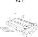
- an image forming apparatus 1 may include an image forming apparatus body 10 and a developing device 100.
- the image forming apparatus body 10 has a transfer path formed therein to transfer a printing medium using transferring means such as rollers and has various of parts housed therein for forming an image on the transferred printing medium.
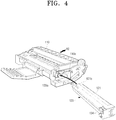
- the developing device 100 enters the image forming apparatus body 10 in the direction R2 (See FIG. 4 ), and may be mounted in the image forming apparatus body 10.
- the developing device 100 may include a developing cartridge 110, a developer containing unit 120, and shutter units 130 as shown in FIG. 2 .
- the developing cartridge 110 may be employed to develop an electrostatic latent image formed on a photoconductive medium 20 with developer, and may include a developing roller 111 to develop the electrostatic latent image of the photoconductive medium 20 and a supply roller 112 to supply developer to the developing roller 111. Also, the developing cartridge 110 may further include first and second agitating rollers 113 and 114 to agitate the developer in the developing cartridge 110 and to uniformly transfer the developer to the supply roller 112.
- the photoconductive medium 20 may be mounted in the developing cartridge 110, and also, a cleaning blade 21 for cleaning a remaining developer off the photoconductive medium 20 may be supported in the developing cartridge 110.
- the photoconductive medium 20 and/or the cleaning blade 21 may be disposed in the image forming apparatus separately from the developing device 100.
- the developer containing unit 120 may contain a quantity of developer therein, and, as shown in FIG. 4 , is removably mounted in the developing cartridge 110.
- the developing cartridge 110 has a mounting recess 110a (see FIG. 4 ) for accommodating the developer containing unit 120.
- the mounting recess 110a may be formed to extend along the length of, and from one end to the other end of, the developing cartridge 110, penetrating through the developing cartridge 110, and may have a predetermined depth. and a predetermined length parallel to the direction R1 perpendicular to the mounting direction R2 (see FIG. 4 ) of the developing cartridge 110. Accordingly, the developer containing unit 120 enters the developing cartridge 110 in the direction of R1 perpendicular to the mounting direction R2 of the developing cartridge 110.
- the developer containing unit 120 if the developer containing unit 120 is mounted in the developing cartridge 110, the developer containing unit 120 forms a developer transfer paths T1 and T2 in association with the developing cartridge 110.
- the developer containing unit 120 is a developer cartridge 121 that supplies the developer to the developing cartridge 110, and may also collect waste developer discharged from the developing cartridge 110.
- the developer transfer paths T1 and T2 formed between the developer cartridge 121 and the developing cartridge 110 are, respectively, a supply path T1, through which the developer is supplied from the developer cartridge 121 to the developing cartridge 110, and a collecting path T2, through which waste developer discharged from the developing cartridge 110 is collected in the developer cartridge 121.
- the supply path T1 includes first and second transfer openings 122 and 116, which are formed in the developer cartridge 121 and in the developing cartridge 110, respectively, such that they face each other, and fluidly communicate with each other if the developer cartridge 121 is mounted in the developing cartridge 110.
- the first transfer opening 122 serves as an outlet through which the developer is discharged from the developer cartridge 121
- the second transfer opening 116 serves as an inlet through which the developer flows into the developing cartridge 110.
- the developer cartridge 121 may have a developer transfer member 124 rotatably formed therein to transfer the developer from the developer cartridge 121 to the supply path T1 through the first transfer opening 122.
- the collecting path T2 may include third and fourth transfer openings 117 and 123, which are formed in the developing cartridge 110 and in the developer cartridge 121, respectively, such that they face, and fluidly communicate with, each other if the developer cartridge 121 is mounted in the developing cartridge 110.
- the third transfer opening 117 serves as the waste developer outlet, through which the waste developer is discharged from the developing cartridge 110, and the fourth transfer opening 123 serves as the waste developer inlet, through which the waste developer flows into the developer cartridge 121.
- the waste developer is developer that has been cleaned off the photoconductive medium 20 by the cleaning blade 21, and, as shown in FIGS 2 and 3 , is transferred to the collecting path T2 by waste developer transferring mechanism 22.
- the waste developer transferring mechanism 22 may include a waste developer transfer member 23 and a waste developer transfer pipe 24.
- the supply path T1 and the collecting path T2 are formed in the proximity of the entering or leading end and an exiting or trailing end of the developer cartridge 121, respectively, with reference to the mounting direction of the developer cartridge 121.
- the shutter units 130 opens the developer transfer paths T1 and T2 only if the developer cartridge 121 is mounted in the developing cartridge 110. That is, the shutter units 130 opens both the supply path T1 and the collecting path T2 if the developer cartridge 121 is mounted in the developing cartridge 110, and conversely, closes both of them if the developer cartridge 121 is removed from the developing cartridge 110.
- the shutter unit 130 includes first through fourth shutter members 131, 132, 133, 134 corresponding to the first through fourth transfer openings 122, 116, 117, 123.
- the first and the second shutter members 131, 132 are disposed in the developer cartridge 121 and the developing cartridge 110, respectively, to open and close the first and the second transfer openings 122 and 116, respectively.
- the third and the fourth shutter members 133 and 134 are disposed in the developing cartridge 110 and the developer cartridge 121, respectively, to open and close the third and the fourth transfer openings 117 and 123, respectively.
- the first, the second, and the fourth shutter members 131, 132, 134 open the first, the second, and the fourth transfer openings 122, 116, 123 if the developer cartridge 121 is mounted in the mounting recess 110a of the developing cartridge 110 in the first direction R1. Also, the third shutter member 133 opens the third transfer opening 116 if the developing cartridge 110 is mounted in the image forming apparatus body 10 in the second direction R2.
- the first through fourth shutter members 131, 132, 133, 134 described above are elastically supported by first through fourth elastic members 135, 136, 137, 138, respectively, in directions of closing the first through the fourth transfer openings 122, 116, 117, 123.
- the first shutter member 131 is prevented from moving further in the direction R1 by the locking projection 131b formed in the proximity of the second transfer opening 116 of the developing cartridge 110, thereby opening the first transfer opening 122 . That is, although the developer cartridge 121 moves in the first direction R1, the first shutter member 131 is interfered by the locking projection 131b, and does not move in the first direction R1 such that the first transfer opening 122 of the developer cartridge 121 is opened.
- the end of the first shutter member 131 which is brought into contact with the locking projection 131b, is bent toward the developing cartridge 110 while the other end is supported by the first elastic member 135.
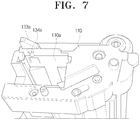
- the guide lever 140 On the locking projection 131b is disposed a guide lever 140 which is rotated by the interference from the developer cartridge 121, and which assists the first shutter member 131 in opening and closing the first transfer opening 122.
- the guide lever 140 includes first and second wings 141 and 142 rotating about a rotary shaft 140a and a pressure protrusion 143.
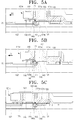
- the first wing 141 is rotated by the bent end of the first shutter member 131 in the first direction R1, and, as shown in FIG. 5C , has a length such that the first wing 141 is brought into contact with the bottom 121c of the developer cartridge 121 facing the developing cartridge 110.
- the second wing 142 may have a shorter length than that of the first wing 141, and may be spaced from the first wing 141 at a predetermined angle. Therefore, the second wing 142 is not brought into contact with the bottom 121c of the developer cartridge 121 when rotated to the position shown in FIG. 5C .
- the pressure protrusion 143 protrudes from the second wing 142 and presses the one end of the first shutter member 131 in the first direction R1 if the first wing 141 is brought into contact with the bottom of the developer cartridge 121.
- the second shutter member 132 is interfered by a leading end 121a of the developer cartridge 121 with reference to the first direction R1, and thus moves in the first direction R1, thereby opening the second transfer opening 116.
- the leading end 121a which enters the mounting recess 110a first with reference to the mounting direction of the developer cartridge 121 i.e. the direction R1, is brought into contact with the second shutter member 132 of the developing cartridge 110, and the other end of the developer cartridge 121 is exposed to the outside through the mounting recess 110a, and forms an outer wall together with the developing cartridge 110 as shown in FIG. 3 .
- the second shutter member 132 has an inclined surface 132a to restore the guide lever 140 to the initial position. More specifically, as shown in FIG. 6C , if the leading end 121a of the developer cartridge 121 moves in the direction R3 opposite to the mounting direction R1, and thus the first wing 141 is released from the contact with the bottom of the developer cartridge 121, the inclined surface 132a of the second shutter member 132, which is free from the contact force with the leading end 121a of the developer cartridge 121, is brought into contact with the first wing 141, and thus, the first wing 141 is rotated in the direction R3 opposite to the mounting direction R1, and is restored to the original position by a recovering force of the second shutter member 132. For this, the inclined surface 132a of the second shutter member 132 is inclined by a predetermined angle corresponding to the initial position of the first wing 141.
- the third shutter member 133 opens the third transfer opening 116 as an interference member 133a protruding from the third shutter member 133 is interfered by the image forming apparatus body 10, and thus moves in the first direction R1. More specifically, if the developing cartridge 110 enters in the second direction R2 and is mounted in the image forming apparatus body 10 with the developer cartridge 121 mounted therein, the interference member 133a protruding from the developing cartridge 110 is brought into contact with the image forming apparatus body 10 and thus moves in the direction R1 such that the third shutter member 122 opens the third transfer opening 116.
- the fourth shutter member 134 moves in the direction R3 opposite to the mounting direction R1 by means of a locking protrusion 134a formed on the developing cartridge 110, thereby opening the fourth opening 123.
- the bent end 131a of the first shutter member 131 is brought into contact with the locking projection 131b and thus is prevented from entering further in the first direction R1.
- the bent end 131a of the first shutter member 131 is also brought into contact with the first wing 141 of the guide lever 140 and thus rotates the first wing 141 in the first direction R1 as shown in FIGS. 5A and 5B .
- the developer cartridge 121 continues to enter in the first direction R1 and thus moves the second shutter member 132 which is in contact with the leading end 121a of the developer cartridge 121 in the first direction R1.
- the first and the second transfer openings 122 are 116 are opened by the first and the second shutter members 131 and 132 such that the supply path T1 for transferring the developer from the developer cartridge 121 to the developing cartridge 110 is open.
- the first wing 141 which has rotated in contact with one end of the first shutter member 131 in the first direction R1, is in contact with the bottom of the developer cartridge 121 and is prevented from rotating in the first direction R1 as shown in FIG. 5C . Accordingly, the one end of the first shutter member 131 is released from the contact with the first wing 141, and, instead, is brought into contact with the pressure protrusion 143 protruding from the second wing 142 spaced from the first wing 141 by a predetermined angle.
- the bent end 131a of the first shutter member 131 is fixedly at the location between the locking projection 131b and the pressure protrusion 143 such that the first shutter member 131 is fixed at the position of opening the first transfer opening 122.
- the fourth shutter member 134 is brought into contact with the locking protrusion 134a formed on the developing cartridge 110, and thus moves in the direction R3 opposite the mounting direction R1, thereby opening the fourth transfer opening 123.
- the first, the second, and the fourth transfer openings 122, 116 and 123 are all open by the first, the second and the fourth shutter members 131, 132 and 134, respectively.
- the developing cartridge 110 enters the image forming apparatus body 10 in the second direction R2 with the developer cartridge 121 mounted therein.
- the interference member 133a protruding from the third shutter member 133 to protrude from the developing cartridge 110 is brought into contact with the image forming apparatus body 10, thereby moving the third shutter member 133 in the first direction R1.
- the third transfer opening 116 becomes open by the third shutter member 133 such that the developer supply path T1 and the collecting path T2 between the developer cartridge 121 and the developing cartridge 110 are all open.
- the first and the second shutter members 131 and 132 open the first and the second transfer openings 122 and 116 in sequence in association with the mounting operation of the developer cartridge 121, and then, the fourth transfer opening 123 of the developer cartridge 121 is opened by the fourth shutter member 134.
- the third transfer opening 117 is opened by the third shutter member 133 such that the developer collecting path T2 is finally opened. That is, the shutter units 130 opens the developer supply path T1 first, and then opens the developer collecting path T2.
- the developing cartridge 110 is dismounted from the image forming apparatus body 10 in a direction R4 opposite to the second direction R2, at which time, the interference member 133a is released from the interference force from the image forming apparatus body 10 such that the interference member 133a is restored to an initial position by an elastic force of the third elastic member 137. Accordingly, the third shutter member 133 closes the third transfer opening 116 in association with the movement of the interference member 133a.
- the developer cartridge 121 may be removed in the direction R3 opposite to the mounting direction R1.
- the first, the second, and the fourth shutter members 131, 132 and 134 being free from the mounting force between the developer cartridge 121 and the developing cartridge 110, are released from the contacts with respect to the locking projection 131b, the leading end 121a of the developer cartridge 121, and the locking protrusion 134a, respectively. Accordingly, the first, the second, and the fourth shutter members 131, 132 and 134 are restored into their respective initial positions by elastic bias from the first, the second and the fourth elastic members 135, 136 and 138.
- a recovering force of the second elastic member 136 for restoring the second shutter member 132 is exerted in the direction R3 opposite to the mounting direction R1 of the developer cartridge 121, assisting in the dismounting the developer cartridge 121 from the developing cartridge 110.
- the pressure protrusion 143 of the guide lever 140 presses and supports the bent end of the first shutter member 131 in the first direction R1 until the first wing 141 is released from the contact with the bottom of the developing cartridge 121. Consequently, the pulling by the guide lever 140 of first shutter member 131 in the first direction R1, in addition to the recovering force of the first elastic member 135 toward the first direction R1, acts to completely close the first transfer opening 122.
- the contact force between the pressure protrusion 143 and the first shutter member 131 is maintained until the first wing 141 becomes free from the contact force with respect to the bottom 121c of the developer cartridge 121, and is rotated by the inclined surface 132a of the second shutter member 132 in the opposite direction of the mounting direction R1 to release the bent end 131a of the first shutter member 131 from the pressure protrusion 143.
- the inclined surface 132a of the second shutter member 132 interferes with, and further rotates, the first wing 141 in the direction R3, thereby restoring the guide lever 140 to the initial position.
- the third transfer opening 117 of the developing cartridge 110 is first closed by the third shutter member 133.
- the fourth transfer opening 123 is closed by the fourth shutter member 134 and then the first and the second transfer openings 122 and 116 are closed by the first and the second shutter members 131 and 132. That is, as the developer cartridge 121 is dismounted, the developer collecting path T2 is closed first and then the developer supply path T1 is closed.
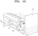
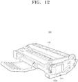
- FIGS. 11 and 12 illustrate an image forming apparatus according to another embodiment of the present invention.
- a developing device 200 of an image forming apparatus 1 is similar to the developing device 100 of the image forming apparatus of previously described embodiment in that it includes a developing cartridge, a developer containing unit 120, and a shutter 130.
- the elements similar to those of the previously embodiment are assigned with the same reference numerals, and were previously described with reference to FIGS. 1 through 10 .
- the developing device 200 includes a waste developer container 221, which does not contain developer for supplying to the developing cartridge 110, but has a structure for collecting waste developer discharged from the developing cartridge 110. Unlike the developer cartridge 121 of the previous embodiment, the waste developer container 221 includes only a collecting path T2 as the developer transfer path.
- the developing device 200 may have a quantity of developer in the developing cartridge sufficient for printing a number of printing medium.
- a developer cartridge 121 as illustrated in the previous embodiments e.g., may be mounted in the mounting recess 110a of the developing cartridge 110, replacing the waste developer container 221.
- the shutter unit 130 includes third and fourth shutter members 133 and 134 disposed in the developing cartridge 110 and the waste developer container 221, respectively, to open and close the third and the fourth transfer openings 117 and 123.
- the third and the fourth shutter members 133 and 134 opens the third and the fourth transfer openings 117 and 123, respectively as the developing cartridge 110 is mounted in the image forming apparatus body 10 and the waste developer container 221 is mounted in the developing cartridge 10. Also, the third and the fourth shutter members 133 and 134 are elastically supported by third and fourth elastic members 137 and 138 in directions of closing the third and the fourth transfer openings 117 and 123.
- the third and the fourth shutter members 133 and 134 are interfered by the image forming apparatus body 10 and by a locking protrusion 134a formed on the developing cartridge 110, respectively, and thus are made to move in the direction R1, thereby opening the third and the fourth transfer openings 117 and 123.
- the image forming apparatus can be used economically.
- the transfer path for the developer is selectively opened and closed in association with operations of mounting and dismounting the developer cartridge 121 containing the developer and/or the waste developer container 221 in and from the developing cartridge 110, a developer leak may be reduced during the replacement. Therefore, contaminations due to developer leak may be prevented.
Landscapes
- Physics & Mathematics (AREA)
- General Physics & Mathematics (AREA)
- Life Sciences & Earth Sciences (AREA)
- Engineering & Computer Science (AREA)
- Environmental & Geological Engineering (AREA)
- Sustainable Development (AREA)
- Dry Development In Electrophotography (AREA)
- Electrophotography Configuration And Component (AREA)
- Cleaning In Electrography (AREA)
Claims (5)
- Entwicklungsvorrichtung einer Bilderzeugungseinrichtung, die Folgendes umfasst:eine Entwicklungskartusche;eine Entwicklerkartusche (120), die sowohl eine Menge an Entwickler, der an die Entwicklungskartusche zu liefern ist, als auch Abfallentwickler, der aus der Entwicklungskartusche ausgegeben wurde, enthält;wobei die Entwicklerkartusche (120) austauschbar in der Entwicklungskartusche angeordnet ist, so dass ein Entwicklertransferpfad (T1, T2) gebildet wird, der fluid mit der Entwicklungskartusche kommuniziert, wobei der Entwicklertransferpfad einen Versorgungspfad (T1), durch den die Menge an Entwickler von der Entwicklerkartusche zu der Entwicklungskartusche transferiert wird, und einen Sammelpfad (12), durch den der Abfallentwickler von der Entwicklungskartusche zu der Entwicklerkartusche transferiert wird, umfasst; undeine Verschlusseinheit (130), die den Entwicklertransferpfad öffnet, wenn die Entwicklerkartusche in der Entwicklungskartusche montiert ist, und die den Entwicklertransferpfad schließt, wenn die Entwicklerkartusche aus der Entwicklungskartusche entfernt ist,wobei der Versorgungspfad ein erstes und zweites Transferloch (122, 116) umfasst, die jeweils in der Entwicklerkartusche und der Entwicklungskartusche gebildet sind, so dass sie fluid miteinander kommunizieren, wenn die Entwicklerkartusche in der Entwicklungskartusche montiert ist, undwobei der Sammelpfad ein drittes und viertes Transferloch (117, 123) umfasst, die jeweils in der Entwicklungskartusche und der Entwicklerkartusche gebildet sind, so dass sie fluid miteinander kommunizieren, wenn die Entwicklerkartusche in der Entwicklungskartusche montiert ist; undwobei die Verschlusseinheit (130) ein erstes und zweites Verschlusselement (131, 132) umfasst, die jeweils in der Entwicklerkartusche und der Entwicklungskartusche angeordnet sind, um das erste und das zweite Transferloch (122, 116) zu öffnen und zu schließen, undwobei die Verschlusseinheit ein drittes und viertes Verschlusselement (133, 134) umfasst, die jeweils in der Entwicklungskartusche und der Entwicklerkartusche angeordnet sind, um das dritte und das vierte Transferloch (117, 123) zu öffnen und zu schließen, dadurch gekennzeichnet, dass die Entwicklungsvorrichtung so ausgelegt ist, dass:nachdem das erste und/oder das zweite Verschlusselement (131, 132) ein entsprechendes jeweiliges des ersten und des zweiten Transferlochs (122, 116) während eines Prozesses des Montierens der Entwicklerkartusche in einer ersten Richtung (R1) in einer Montageaussparung, die in der Entwicklungskartusche gebildet ist, geöffnet hat, das vierte Verschlusselement (134) das vierte Transferloch (123) während des Prozesses des Montierens der Entwicklerkartusche in der ersten Richtung (R1) in der Montageaussparung, die in der Entwicklungskartusche gebildet ist, öffnet, wonach das dritte Verschlusselement (133) das dritte Transferloch (117) während eines Prozesses des Montierens der Entwicklungskartusche (110) mit der Entwicklerkartusche darin montiert in dem Bilderzeugungseinrichtungskörper in einer zweiten Richtung (R2) senkrecht zu einer ersten Richtung (R1) öffnet.
- Entwicklungsvorrichtung nach Anspruch 1, wobei wenigstens eines des ersten bis vierten Verschlusselements durch ein erstes bis viertes elastisches Element (135, 136, 137, 138) in Richtungen zum Schließen des ersten bis vierten Transferlochs elastisch vorgespannt ist.
- Entwicklungsvorrichtung nach Anspruch 1, wobei die Entwicklungskartusche mit einem Abfallentwicklertransfermittel (22) zum Transferieren des Abfallentwicklers, der von einem organischen fotoleitfähigen Medium gesäubert wurde, durch den Sammelpfad zu der Entwicklerkartusche versehen ist.
- Entwicklungsvorrichtung nach einem der Ansprüche 1 bis 3, wobei die entwicklerenthaltende Einheit ferner einen Abfallentwicklerbehälter (221) umfasst, der keinen Entwickler enthält, der an die Entwicklungskartusche zu liefern ist und der Abfallentwickler sammelt, der aus der Entwicklungskartusche ausgegeben wurde,
wobei der Entwicklertransferpfad (T2) einen Sammelpfad beinhaltet, durch den der Abfallentwickler von der Entwicklungskartusche zu dem Abfallentwicklerbehälter transferiert wird. - Entwicklungsvorrichtung nach Anspruch 2, wobei das erste und das vierte Verschlusselement durch ein erstes und viertes elastisches Element (135, 138) in einer Richtung zum Schließen des ersten und vierten Transferlochs elastisch vorgespannt sind.
Applications Claiming Priority (1)
| Application Number | Priority Date | Filing Date | Title |
|---|---|---|---|
| KR1020080016469A KR100912900B1 (ko) | 2008-02-22 | 2008-02-22 | 현상제카트리지, 현상장치 및 이를 포함하는 화상형성장치 |
Publications (3)
| Publication Number | Publication Date |
|---|---|
| EP2093626A2 EP2093626A2 (de) | 2009-08-26 |
| EP2093626A3 EP2093626A3 (de) | 2012-05-09 |
| EP2093626B1 true EP2093626B1 (de) | 2017-08-09 |
Family
ID=40626837
Family Applications (1)
| Application Number | Title | Priority Date | Filing Date |
|---|---|---|---|
| EP09152577.4A Expired - Fee Related EP2093626B1 (de) | 2008-02-22 | 2009-02-11 | Entwicklungsvorrichtung |
Country Status (7)
| Country | Link |
|---|---|
| US (1) | US8422915B2 (de) |
| EP (1) | EP2093626B1 (de) |
| KR (1) | KR100912900B1 (de) |
| CN (1) | CN101515135B (de) |
| BR (1) | BRPI0805399B1 (de) |
| ES (1) | ES2642048T3 (de) |
| RU (1) | RU2411564C2 (de) |
Families Citing this family (14)
| Publication number | Priority date | Publication date | Assignee | Title |
|---|---|---|---|---|
| JP5531579B2 (ja) * | 2008-11-27 | 2014-06-25 | 株式会社リコー | 粉体補給装置、画像形成装置及び粉体容器 |
| JP5056929B2 (ja) * | 2010-09-27 | 2012-10-24 | 富士ゼロックス株式会社 | 粉体収容容器、画像形成装置 |
| JP5696935B2 (ja) * | 2011-02-21 | 2015-04-08 | 株式会社リコー | 粉体補給装置及び画像形成装置 |
| KR101532204B1 (ko) * | 2011-01-24 | 2015-06-29 | 삼성전자 주식회사 | 화상형성장치 |
| MX362932B (es) | 2012-06-03 | 2019-02-27 | Ricoh Co Ltd | Contenedor de polvo y aparato formador de imagenes. |
| KR20140135347A (ko) * | 2013-05-16 | 2014-11-26 | 삼성전자주식회사 | 현상장치 및 이를 갖는 화상형성장치 |
| KR102048753B1 (ko) | 2013-10-25 | 2019-11-27 | 휴렛-팩커드 디벨롭먼트 컴퍼니, 엘.피. | 화상 형성장치 및 화상 형성장치의 메인티넌스 방법 |
| KR20150098421A (ko) | 2014-02-20 | 2015-08-28 | 삼성전자주식회사 | 카트리지 유닛 및 이를 구비하는 전자사진방식 화상형성장치 |
| US9851657B2 (en) * | 2014-08-22 | 2017-12-26 | Sharp Kabushiki Kaisha | Image forming apparatus |
| JP6380646B2 (ja) * | 2015-02-17 | 2018-08-29 | 京セラドキュメントソリューションズ株式会社 | 現像剤容器およびこれを備える画像形成装置 |
| JP7005249B2 (ja) | 2017-09-21 | 2022-01-21 | キヤノン株式会社 | 現像剤補給容器及び現像剤補給システム |
| JP7051347B2 (ja) | 2017-09-21 | 2022-04-11 | キヤノン株式会社 | 現像剤補給容器及び現像剤補給システム |
| JP7119502B2 (ja) | 2018-03-30 | 2022-08-17 | ブラザー工業株式会社 | 現像カートリッジ |
| CN111562731A (zh) * | 2020-06-09 | 2020-08-21 | 江西凯利德科技有限公司 | 显影剂供应装置 |
Family Cites Families (50)
| Publication number | Priority date | Publication date | Assignee | Title |
|---|---|---|---|---|
| JPS60238873A (ja) | 1984-05-11 | 1985-11-27 | Fuji Xerox Co Ltd | トナ−補給装置 |
| US4974020A (en) | 1986-09-30 | 1990-11-27 | Mita Industrial Co. | Removable developing units for a copying machine and display for indicating the useful life of the machine |
| JPS6491164A (en) | 1987-10-02 | 1989-04-10 | Ricoh Kk | Developing device |
| US4967234A (en) | 1987-11-10 | 1990-10-30 | Ricoh Company, Ltd. | Image forming apparatus |
| KR920010230B1 (ko) * | 1987-11-10 | 1992-11-21 | 가부시기가이샤 리코 | 화상형성장치 |
| JP2965041B2 (ja) | 1988-11-08 | 1999-10-18 | 株式会社リコー | 画像形成装置 |
| US5068691B1 (en) | 1989-06-01 | 1995-01-24 | Fujitsu Ltd | Developing device with a controllable pressure release for the developing roller |
| US5493366A (en) | 1990-09-07 | 1996-02-20 | Konica Corporation | Image forming apparatus |
| JP3060725B2 (ja) | 1992-06-30 | 2000-07-10 | 富士通株式会社 | 現像剤カ−トリッジ及びこれを用いた画像形成装置 |
| JP3110231B2 (ja) | 1993-11-18 | 2000-11-20 | キヤノン株式会社 | 現像装置及びプロセスカートリッジ |
| US5614996A (en) | 1994-03-03 | 1997-03-25 | Kyocera Corporation | Toner storage unit, residual toner collect unit, toner container with these units and image forming apparatus with such toner container |
| JP3244992B2 (ja) | 1994-03-15 | 2002-01-07 | キヤノン株式会社 | 電子写真画像形成装置 |
| JP3263533B2 (ja) | 1994-05-17 | 2002-03-04 | ブラザー工業株式会社 | トナー残量検出装置及びそのトナー収納装置 |
| US5734953A (en) | 1995-02-17 | 1998-03-31 | Ricoh Company, Ltd. | Detachable toner supply and processing assembly for an image forming apparatus and having a shutter mechanism for toner flow control |
| JPH0922177A (ja) | 1995-07-04 | 1997-01-21 | Canon Inc | トナーカートリッジ、プロセスカートリッジ、トナーホッパー及び画像形成装置 |
| JPH10142910A (ja) | 1996-11-08 | 1998-05-29 | Katsuragawa Electric Co Ltd | トナー供給方式 |
| JP3037194B2 (ja) | 1997-04-25 | 2000-04-24 | 新潟日本電気株式会社 | プロセスカートリッジへのトナーの供給方法及び画像形成装置用プロセスカートリッジ |
| US6968139B2 (en) | 1997-06-19 | 2005-11-22 | Canon Kabushiki Kaisha | Toner supply container and electrophotographic image forming apparatus |
| JPH1124513A (ja) | 1997-06-27 | 1999-01-29 | Canon Inc | トナー補給装置及び電子写真画像形成装置 |
| JP3408166B2 (ja) | 1997-09-30 | 2003-05-19 | キヤノン株式会社 | トナー供給容器及び電子写真画像形成装置 |
| JP3321728B2 (ja) * | 1997-11-06 | 2002-09-09 | 京セラミタ株式会社 | 画像形成機のトナー補給装置およびこれに用いるトナーカートリッジ |
| JP3721749B2 (ja) | 1997-11-12 | 2005-11-30 | コニカミノルタビジネステクノロジーズ株式会社 | 画像形成装置のユニットおよびそのユニットを用いる画像形成装置および画像形成装置のユニット検出装置および画像形成装置のユニット検出方法 |
| JP3604919B2 (ja) | 1998-08-31 | 2004-12-22 | キヤノン株式会社 | カラー電子写真画像形成装置及び現像カートリッジ |
| JP3627528B2 (ja) | 1998-09-02 | 2005-03-09 | 富士ゼロックス株式会社 | 現像装置 |
| JP3366295B2 (ja) * | 1998-10-12 | 2003-01-14 | コピア株式会社 | 画像形成装置 |
| JP4054521B2 (ja) | 1999-11-29 | 2008-02-27 | キヤノン株式会社 | 現像剤補給カートリッジ及び現像剤補給システム |
| DE10043016B4 (de) | 2000-09-01 | 2006-11-23 | Walter Ag | Bohrnutenfräser |
| KR100362390B1 (ko) | 2000-12-29 | 2002-11-23 | 삼성전자 주식회사 | 화상형성장치의 현상기-토너 카트리지 조립체 |
| JP4672893B2 (ja) * | 2001-03-30 | 2011-04-20 | キヤノン株式会社 | 現像剤補給容器、及び画像形成装置 |
| US6751428B2 (en) | 2001-09-13 | 2004-06-15 | Brother Kogyo Kabushiki Kaisha | Image forming device and detachably loaded process unit |
| JP3534104B2 (ja) | 2001-12-20 | 2004-06-07 | 富士ゼロックス株式会社 | 画像形成装置及びこれに用いられるプロセスカートリッジ、現像装置 |
| JP3982346B2 (ja) | 2002-06-28 | 2007-09-26 | コニカミノルタビジネステクノロジーズ株式会社 | 画像形成装置のトナーカートリッジ |
| EP1898274B1 (de) * | 2002-09-24 | 2011-04-20 | Ricoh Company, Ltd. | Bilderzeugungsvorrichtung mit einem Bildträgerelement und einem Schutzverschluss |
| JP2004170955A (ja) | 2002-11-08 | 2004-06-17 | Canon Inc | 画像形成装置及びカートリッジ、画像形成システム、カートリッジ用メモリ媒体 |
| JP4242667B2 (ja) | 2003-02-28 | 2009-03-25 | 株式会社東芝 | トナーカートリッジ及び画像形成装置 |
| US7076179B2 (en) | 2003-03-20 | 2006-07-11 | Seiko Epson Corporation | Image forming apparatus and a storage controlling method for information on an improper detachment of developer cartridge to be written in a cartridge storage means |
| JP3673793B2 (ja) | 2003-08-29 | 2005-07-20 | キヤノン株式会社 | プロセスカートリッジ、プロセスカートリッジの装着機構及び電子写真画像形成装置 |
| JP4378221B2 (ja) | 2003-10-08 | 2009-12-02 | キヤノン株式会社 | プロセスカートリッジ及び電子写真画像形成装置 |
| KR100553897B1 (ko) | 2003-10-31 | 2006-02-24 | 삼성전자주식회사 | 메모리를 이용한 화상형성장치의 소모품 관리 장치 |
| JP4525167B2 (ja) | 2004-05-14 | 2010-08-18 | 富士ゼロックス株式会社 | 現像剤回収機構及び画像形成装置 |
| JP2005338329A (ja) | 2004-05-26 | 2005-12-08 | Fuji Xerox Co Ltd | プロセスカートリッジ及び画像形成装置 |
| JP4645116B2 (ja) | 2004-09-22 | 2011-03-09 | 富士ゼロックス株式会社 | プロセスカートリッジ及びこれを有する画像形成装置 |
| KR20060034168A (ko) | 2004-10-18 | 2006-04-21 | 삼성전자주식회사 | 화상형성기기의 상형성장치 |
| JP4651011B2 (ja) | 2005-04-28 | 2011-03-16 | 株式会社リコー | 現像装置、プロセスカートリッジ及び画像形成装置 |
| KR100677595B1 (ko) | 2005-06-10 | 2007-02-02 | 삼성전자주식회사 | 현상기 및 이를 채용한 칼라화상형성장치 |
| JP4315933B2 (ja) | 2005-07-21 | 2009-08-19 | 株式会社沖データ | 現像剤カートリッジ、現像装置、及び画像形成装置 |
| KR100756044B1 (ko) * | 2005-08-29 | 2007-09-07 | 삼성전자주식회사 | 현상제통과 현상제 공급장치 및 이를 가지는 화상형성장치 |
| JP4622774B2 (ja) * | 2005-09-21 | 2011-02-02 | ブラザー工業株式会社 | 画像形成装置、現像装置、及びトナーカートリッジ |
| JP4681489B2 (ja) | 2006-03-31 | 2011-05-11 | 株式会社沖データ | トナーカートリッジ、現像装置、及び画像形成装置 |
| JP4710760B2 (ja) | 2006-08-29 | 2011-06-29 | 富士ゼロックス株式会社 | 現像剤搬送装置および画像形成装置 |
-
2008
- 2008-02-22 KR KR1020080016469A patent/KR100912900B1/ko active IP Right Grant
- 2008-09-29 US US12/240,716 patent/US8422915B2/en active Active
- 2008-11-11 CN CN2008101740154A patent/CN101515135B/zh not_active Expired - Fee Related
- 2008-12-09 RU RU2008148633/28A patent/RU2411564C2/ru active
- 2008-12-10 BR BRPI0805399-5A patent/BRPI0805399B1/pt not_active IP Right Cessation
-
2009
- 2009-02-11 ES ES09152577.4T patent/ES2642048T3/es active Active
- 2009-02-11 EP EP09152577.4A patent/EP2093626B1/de not_active Expired - Fee Related
Non-Patent Citations (1)
| Title |
|---|
| None * |
Also Published As
| Publication number | Publication date |
|---|---|
| BRPI0805399A2 (pt) | 2009-10-06 |
| RU2008148633A (ru) | 2010-06-20 |
| CN101515135B (zh) | 2013-08-21 |
| EP2093626A2 (de) | 2009-08-26 |
| BRPI0805399B1 (pt) | 2019-10-01 |
| RU2411564C2 (ru) | 2011-02-10 |
| KR100912900B1 (ko) | 2009-08-20 |
| ES2642048T3 (es) | 2017-11-15 |
| US8422915B2 (en) | 2013-04-16 |
| US20090214269A1 (en) | 2009-08-27 |
| CN101515135A (zh) | 2009-08-26 |
| EP2093626A3 (de) | 2012-05-09 |
Similar Documents
| Publication | Publication Date | Title |
|---|---|---|
| EP2093626B1 (de) | Entwicklungsvorrichtung | |
| US6526243B2 (en) | Developing unit-toner cartridge assembly of image forming apparatus | |
| JP5110866B2 (ja) | プロセスカートリッジと画像形成装置 | |
| EP2237112B1 (de) | Entwicklerspeicherkörper, Bilderzeugungseinheit und Bilderzeugungsvorrichtung | |
| KR20010061976A (ko) | 현상제 공급 카트리지, 현상제 수용 카트리지, 프로세스카트리지 및 화상 형성 장치 | |
| EP1367459A1 (de) | Entwicklerbehälter für ein Bilderzeugungsgerät mit einer Resttonerkammer | |
| JP5870538B2 (ja) | 画像形成装置およびカートリッジ | |
| JP4562941B2 (ja) | 画像形成装置 | |
| JP2011118040A (ja) | 画像形成ユニット及び画像形成装置 | |
| EP0715225A1 (de) | Entwicklungsgerät | |
| EP2597528B1 (de) | Entwicklungsmechanismus und Bilderzeugungsvorrichtung | |
| WO2014017358A1 (ja) | 画像形成装置 | |
| JP7131179B2 (ja) | 画像形成装置 | |
| JP3714161B2 (ja) | 画像形成装置 | |
| JPH1195638A (ja) | 作像ユニット | |
| KR100846834B1 (ko) | 토너 카트리지 | |
| CN102707596A (zh) | 图像形成结构、图像形成设备和显影装置 | |
| JP2002072817A (ja) | 画像形成装置用ユニット、収納容器、画像形成装置用ユニットと収納容器のアセンブリ、および画像形成装置 | |
| KR100385047B1 (ko) | 레이저 프린터의 토너 카트리지 및 폐토너 회수시스템 | |
| JP5459735B2 (ja) | 画像形成装置 | |
| JP4603859B2 (ja) | トナー供給手段及び画像形成装置 | |
| JP5533580B2 (ja) | 画像形成装置 | |
| JPH0633480Y2 (ja) | 現像装置 | |
| JP4092049B2 (ja) | 画像形成装置 | |
| JP2023023845A (ja) | 現像剤補給装置、及び、画像形成装置 |
Legal Events
| Date | Code | Title | Description |
|---|---|---|---|
| PUAI | Public reference made under article 153(3) epc to a published international application that has entered the european phase |
Free format text: ORIGINAL CODE: 0009012 |
|
| 17P | Request for examination filed |
Effective date: 20090211 |
|
| AK | Designated contracting states |
Kind code of ref document: A2 Designated state(s): AT BE BG CH CY CZ DE DK EE ES FI FR GB GR HR HU IE IS IT LI LT LU LV MC MK MT NL NO PL PT RO SE SI SK TR |
|
| AX | Request for extension of the european patent |
Extension state: AL BA RS |
|
| PUAL | Search report despatched |
Free format text: ORIGINAL CODE: 0009013 |
|
| AK | Designated contracting states |
Kind code of ref document: A3 Designated state(s): AT BE BG CH CY CZ DE DK EE ES FI FR GB GR HR HU IE IS IT LI LT LU LV MC MK MT NL NO PL PT RO SE SI SK TR |
|
| AX | Request for extension of the european patent |
Extension state: AL BA RS |
|
| RIC1 | Information provided on ipc code assigned before grant |
Ipc: G03G 15/08 20060101AFI20120402BHEP Ipc: G03G 21/12 20060101ALI20120402BHEP |
|
| 17Q | First examination report despatched |
Effective date: 20120423 |
|
| RAP1 | Party data changed (applicant data changed or rights of an application transferred) |
Owner name: SAMSUNG ELECTRONICS CO., LTD. |
|
| AKX | Designation fees paid |
Designated state(s): DE ES FR GB IT |
|
| RAP1 | Party data changed (applicant data changed or rights of an application transferred) |
Owner name: S-PRINTING SOLUTION CO., LTD. |
|
| RIC1 | Information provided on ipc code assigned before grant |
Ipc: G03G 21/10 20060101ALI20170404BHEP Ipc: G03G 15/08 20060101AFI20170404BHEP Ipc: G03G 21/12 20060101ALI20170404BHEP |
|
| GRAP | Despatch of communication of intention to grant a patent |
Free format text: ORIGINAL CODE: EPIDOSNIGR1 |
|
| INTG | Intention to grant announced |
Effective date: 20170524 |
|
| GRAS | Grant fee paid |
Free format text: ORIGINAL CODE: EPIDOSNIGR3 |
|
| GRAA | (expected) grant |
Free format text: ORIGINAL CODE: 0009210 |
|
| AK | Designated contracting states |
Kind code of ref document: B1 Designated state(s): DE ES FR GB IT |
|
| REG | Reference to a national code |
Ref country code: GB Ref legal event code: FG4D |
|
| REG | Reference to a national code |
Ref country code: DE Ref legal event code: R096 Ref document number: 602009047600 Country of ref document: DE |
|
| REG | Reference to a national code |
Ref country code: ES Ref legal event code: FG2A Ref document number: 2642048 Country of ref document: ES Kind code of ref document: T3 Effective date: 20171115 |
|
| REG | Reference to a national code |
Ref country code: FR Ref legal event code: PLFP Year of fee payment: 10 |
|
| REG | Reference to a national code |
Ref country code: DE Ref legal event code: R097 Ref document number: 602009047600 Country of ref document: DE |
|
| PLBE | No opposition filed within time limit |
Free format text: ORIGINAL CODE: 0009261 |
|
| STAA | Information on the status of an ep patent application or granted ep patent |
Free format text: STATUS: NO OPPOSITION FILED WITHIN TIME LIMIT |
|
| RAP2 | Party data changed (patent owner data changed or rights of a patent transferred) |
Owner name: HP PRINTING KOREA CO., LTD. |
|
| 26N | No opposition filed |
Effective date: 20180511 |
|
| REG | Reference to a national code |
Ref country code: DE Ref legal event code: R082 Ref document number: 602009047600 Country of ref document: DE Ref country code: DE Ref legal event code: R081 Ref document number: 602009047600 Country of ref document: DE Owner name: HP PRINTING KOREA CO., LTD., SUWON-SI, KR Free format text: FORMER OWNER: S-PRINTING SOLUTION CO., LTD., SUWON-SI, GYEONGGI-DO, KR Ref country code: DE Ref legal event code: R081 Ref document number: 602009047600 Country of ref document: DE Owner name: HEWLETT-PACKARD DEVELOPMENT COMPANY, L.P., SPR, US Free format text: FORMER OWNER: S-PRINTING SOLUTION CO., LTD., SUWON-SI, GYEONGGI-DO, KR Ref country code: DE Ref legal event code: R082 Ref document number: 602009047600 Country of ref document: DE Representative=s name: SCHOPPE, ZIMMERMANN, STOECKELER, ZINKLER, SCHE, DE |
|
| REG | Reference to a national code |
Ref country code: ES Ref legal event code: PC2A Owner name: HEWLETT-PACKARD DEVELOPMENT COMPANY, L.P. Effective date: 20191105 |
|
| REG | Reference to a national code |
Ref country code: DE Ref legal event code: R081 Ref document number: 602009047600 Country of ref document: DE Owner name: HEWLETT-PACKARD DEVELOPMENT COMPANY, L.P., SPR, US Free format text: FORMER OWNER: HP PRINTING KOREA CO., LTD., SUWON-SI, GYEONGGI-DO, KR |
|
| REG | Reference to a national code |
Ref country code: GB Ref legal event code: 732E Free format text: REGISTERED BETWEEN 20191212 AND 20191218 |
|
| PGFP | Annual fee paid to national office [announced via postgrant information from national office to epo] |
Ref country code: FR Payment date: 20210608 Year of fee payment: 14 |
|
| REG | Reference to a national code |
Ref country code: DE Ref legal event code: R082 Ref document number: 602009047600 Country of ref document: DE Representative=s name: SCHOPPE, ZIMMERMANN, STOECKELER, ZINKLER, SCHE, DE |
|
| PGFP | Annual fee paid to national office [announced via postgrant information from national office to epo] |
Ref country code: GB Payment date: 20220119 Year of fee payment: 14 Ref country code: DE Payment date: 20210528 Year of fee payment: 14 |
|
| PGFP | Annual fee paid to national office [announced via postgrant information from national office to epo] |
Ref country code: IT Payment date: 20220119 Year of fee payment: 14 Ref country code: ES Payment date: 20220301 Year of fee payment: 14 |
|
| REG | Reference to a national code |
Ref country code: DE Ref legal event code: R119 Ref document number: 602009047600 Country of ref document: DE |
|
| GBPC | Gb: european patent ceased through non-payment of renewal fee |
Effective date: 20230211 |
|
| PG25 | Lapsed in a contracting state [announced via postgrant information from national office to epo] |
Ref country code: GB Free format text: LAPSE BECAUSE OF NON-PAYMENT OF DUE FEES Effective date: 20230211 |
|
| PG25 | Lapsed in a contracting state [announced via postgrant information from national office to epo] |
Ref country code: IT Free format text: LAPSE BECAUSE OF NON-PAYMENT OF DUE FEES Effective date: 20230211 Ref country code: GB Free format text: LAPSE BECAUSE OF NON-PAYMENT OF DUE FEES Effective date: 20230211 Ref country code: FR Free format text: LAPSE BECAUSE OF NON-PAYMENT OF DUE FEES Effective date: 20230228 Ref country code: DE Free format text: LAPSE BECAUSE OF NON-PAYMENT OF DUE FEES Effective date: 20230901 |
|
| REG | Reference to a national code |
Ref country code: ES Ref legal event code: FD2A Effective date: 20240405 |
|
| PG25 | Lapsed in a contracting state [announced via postgrant information from national office to epo] |
Ref country code: ES Free format text: LAPSE BECAUSE OF NON-PAYMENT OF DUE FEES Effective date: 20230212 |
|
| PG25 | Lapsed in a contracting state [announced via postgrant information from national office to epo] |
Ref country code: ES Free format text: LAPSE BECAUSE OF NON-PAYMENT OF DUE FEES Effective date: 20230212 |