EP2091642B1 - Bandschleuse - Google Patents
Bandschleuse Download PDFInfo
- Publication number
- EP2091642B1 EP2091642B1 EP07818961A EP07818961A EP2091642B1 EP 2091642 B1 EP2091642 B1 EP 2091642B1 EP 07818961 A EP07818961 A EP 07818961A EP 07818961 A EP07818961 A EP 07818961A EP 2091642 B1 EP2091642 B1 EP 2091642B1
- Authority
- EP
- European Patent Office
- Prior art keywords
- strip
- sealing
- gate according
- sealing gate
- elements
- Prior art date
- Legal status (The legal status is an assumption and is not a legal conclusion. Google has not performed a legal analysis and makes no representation as to the accuracy of the status listed.)
- Not-in-force
Links
Images


Classifications
-
- B—PERFORMING OPERATIONS; TRANSPORTING
- B01—PHYSICAL OR CHEMICAL PROCESSES OR APPARATUS IN GENERAL
- B01J—CHEMICAL OR PHYSICAL PROCESSES, e.g. CATALYSIS OR COLLOID CHEMISTRY; THEIR RELEVANT APPARATUS
- B01J3/00—Processes of utilising sub-atmospheric or super-atmospheric pressure to effect chemical or physical change of matter; Apparatus therefor
- B01J3/02—Feed or outlet devices therefor
-
- B—PERFORMING OPERATIONS; TRANSPORTING
- B01—PHYSICAL OR CHEMICAL PROCESSES OR APPARATUS IN GENERAL
- B01J—CHEMICAL OR PHYSICAL PROCESSES, e.g. CATALYSIS OR COLLOID CHEMISTRY; THEIR RELEVANT APPARATUS
- B01J3/00—Processes of utilising sub-atmospheric or super-atmospheric pressure to effect chemical or physical change of matter; Apparatus therefor
- B01J3/006—Processes utilising sub-atmospheric pressure; Apparatus therefor
-
- B—PERFORMING OPERATIONS; TRANSPORTING
- B01—PHYSICAL OR CHEMICAL PROCESSES OR APPARATUS IN GENERAL
- B01J—CHEMICAL OR PHYSICAL PROCESSES, e.g. CATALYSIS OR COLLOID CHEMISTRY; THEIR RELEVANT APPARATUS
- B01J3/00—Processes of utilising sub-atmospheric or super-atmospheric pressure to effect chemical or physical change of matter; Apparatus therefor
- B01J3/03—Pressure vessels, or vacuum vessels, having closure members or seals specially adapted therefor
-
- C—CHEMISTRY; METALLURGY
- C23—COATING METALLIC MATERIAL; COATING MATERIAL WITH METALLIC MATERIAL; CHEMICAL SURFACE TREATMENT; DIFFUSION TREATMENT OF METALLIC MATERIAL; COATING BY VACUUM EVAPORATION, BY SPUTTERING, BY ION IMPLANTATION OR BY CHEMICAL VAPOUR DEPOSITION, IN GENERAL; INHIBITING CORROSION OF METALLIC MATERIAL OR INCRUSTATION IN GENERAL
- C23C—COATING METALLIC MATERIAL; COATING MATERIAL WITH METALLIC MATERIAL; SURFACE TREATMENT OF METALLIC MATERIAL BY DIFFUSION INTO THE SURFACE, BY CHEMICAL CONVERSION OR SUBSTITUTION; COATING BY VACUUM EVAPORATION, BY SPUTTERING, BY ION IMPLANTATION OR BY CHEMICAL VAPOUR DEPOSITION, IN GENERAL
- C23C16/00—Chemical coating by decomposition of gaseous compounds, without leaving reaction products of surface material in the coating, i.e. chemical vapour deposition [CVD] processes
-
- F—MECHANICAL ENGINEERING; LIGHTING; HEATING; WEAPONS; BLASTING
- F27—FURNACES; KILNS; OVENS; RETORTS
- F27D—DETAILS OR ACCESSORIES OF FURNACES, KILNS, OVENS, OR RETORTS, IN SO FAR AS THEY ARE OF KINDS OCCURRING IN MORE THAN ONE KIND OF FURNACE
- F27D99/00—Subject matter not provided for in other groups of this subclass
- F27D99/0073—Seals
-
- B—PERFORMING OPERATIONS; TRANSPORTING
- B01—PHYSICAL OR CHEMICAL PROCESSES OR APPARATUS IN GENERAL
- B01J—CHEMICAL OR PHYSICAL PROCESSES, e.g. CATALYSIS OR COLLOID CHEMISTRY; THEIR RELEVANT APPARATUS
- B01J2219/00—Chemical, physical or physico-chemical processes in general; Their relevant apparatus
- B01J2219/00002—Chemical plants
- B01J2219/00027—Process aspects
- B01J2219/00033—Continuous processes
-
- F—MECHANICAL ENGINEERING; LIGHTING; HEATING; WEAPONS; BLASTING
- F27—FURNACES; KILNS; OVENS; RETORTS
- F27D—DETAILS OR ACCESSORIES OF FURNACES, KILNS, OVENS, OR RETORTS, IN SO FAR AS THEY ARE OF KINDS OCCURRING IN MORE THAN ONE KIND OF FURNACE
- F27D99/00—Subject matter not provided for in other groups of this subclass
- F27D99/0073—Seals
- F27D2099/0078—Means to minimize the leakage of the furnace atmosphere during charging or discharging
Definitions
- the invention relates to a belt lock for sealing a first space relative to a second space, wherein both spaces of a band, in particular a metal strip, are passed and wherein at least one sealing means is provided for sealing the spaces.
- Generic belt locks are for example from the DE 44 18 383 C2 and from the DE 199 60 751 A1 known. There it is described that at a lock stage, two sealing rollers abut the belt to seal it, namely a first sealing roller on the upper side and a second sealing roller on the lower side of the belt.
- Such sluice gates are generally used for products having a width to thickness ratio of substantially greater than one. They can also be used to seal against each other chambers, in which different media are used for belt treatment.
- the seal by means of sealing rollers is relatively complex due to the required storage of roles and thus costly. This applies in particular if the width and / or thickness of the band to be sealed changes due to the batch.
- the adaptation of the belt lock to belts of different widths and Thickness is expensive. As a result of the adjustment, the quality of the seal is also adversely affected in some cases.
- the present invention is therefore based on the object, a belt lock of the type mentioned in such a way that in this regard an improvement can be achieved.
- the lock should thus have an improved sealing effect and be adjustable in a simple manner on bands of different width and thickness.
- the sealing means has at least two relatively movable diaphragm elements, which have at least one sealing surface which is adapted to the edge contour of the tape to be sealed.
- At least two of the diaphragm elements are plate-shaped and arranged parallel to each other lying.
- the individual plate-shaped aperture elements are sealingly against each other.
- At least a portion of the shutter members may be associated with actuators to adjust a shutter member in a direction perpendicular to the direction of conveyance of the belt.
- a plurality of diaphragm elements are brought up to the belt in such a way that a passage channel corresponding to its shape results for the belt.
- the diaphragm elements have at least one sealing surface which corresponds to the shape of the band.
- a preferred embodiment provides that two mutually displaceable diaphragm elements are provided, each having a rectangular recess for the passage of the band. This allows - with appropriate displacement of the diaphragm elements - create any rectangular passageways for the band.
- An alternative embodiment provides that two mutually displaceable diaphragm elements are provided, each having two mutually perpendicular sealing surfaces. In the interaction of these diaphragm elements, a rectangular passage for the band can also be generated, which corresponds exactly to the cross-sectional shape of the band.
- a further alternative embodiment of the invention provides that four mutually displaceable diaphragm elements are provided, each having a straight running sealing surface. After that, a total of four partial apertures are thus moved together in such a way that a rectangular passage channel for the tape results.
- One of the diaphragm elements can also be designed as a roller.
- At least one of the diaphragm elements can be pressed by means of at least one spring element with its sealing surface on the belt surface.
- a development provides that at least one guide roller is present, which starts at the edge of the band and guides the band relative to the band lock.
- a special embodiment of the invention provides that at least one diaphragm element is equipped with means for adjusting the effective height or effective width.
- the means for adjusting the effective height or effective width are realized by two panel parts which lie against each other at abutment surfaces cut obliquely to the conveying direction of the band; at least one of the parts is positionable by a moving element in the conveying direction of the belt.
- To stabilize the band can be performed in the conveying direction via two rollers so that there is a twice band deflection before and behind the diaphragm elements.
- the belt lock is preferably used to serve to seal a first space having a first pressure level with respect to a second space with a second, different from the first pressure level pressure level. But it can also be used in pressure equality of the rooms, if in these different media must be sealed against each other; In this case, it is thus provided that the belt sluice is used for sealing a first space with a first process medium with respect to a second space with a second, different from the first process medium process medium.
- a belt lock 1 can be seen, which seals a first space 2 with respect to a second space 3. Between the two chambers 2, 3 there is a pressure difference, which makes the belt lock 1 necessary for its maintenance.
- the belt lock 1 allows a continuous passage of a belt 4, which passes the belt lock 1 in the conveying direction F.
- the sealing means 5 consists in the present case of two diaphragm elements 6 and 7, which are plate-shaped and each having a rectangular recess 16 and 17.
- the dimensions of the rectangular recesses 16, 17 are selected so that the width and the height are greater than the maximum occurring width or height of the tape 4 to be sealed.
- the diaphragm element 6 has two sealing surfaces 10 and 11; the diaphragm element 7 has two sealing surfaces 12 and 13.
- the two diaphragm elements 6, 7 are, as in Fig. 2 can be seen, sealing each other.
- the one panel element 7 in turn rests against a plate-shaped chamber partition wall 28.
- adjusting elements 14 and 15 in Fig. 1 which serve to move the diaphragm elements 6, 7 in their disk plane. This is done until the respective sealing surfaces 10, 11, 12, 13 abut the band 4, whereby the band 4 is then sealed between the spaces 2, 3. The sealing thus takes place by a shape-congruent contact area between the panels 6, 7 and the band 4.
- the aperture elements 6, 7 approached according to the width and thickness of the tape 4 to the tape 4.
- the diaphragm elements 6, 7 can, what is not shown, be positioned by additional guide elements following the band contour (eg guide rollers).
- the sealing of the diaphragm elements 6, 7 with each other via the flat contact or separate sealing elements, in particular sealing surfaces (not shown).
- the sealing of the diaphragm elements 6, 7 to the chamber partition wall 28 also takes place via contact or sealing elements (sealing surfaces).
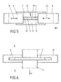
- FIGS. 3 and 4 One too Fig. 1, 2 alternative embodiment of the invention is in the FIGS. 3 and 4 shown.
- two aperture elements 6, 7 are present, but now each have a section that defines two mutually perpendicular sealing surfaces 10, 11 (for the diaphragm element 6) and 12, 13 (for the diaphragm element 7).
- Analogous to the statements related to the Figures 1 and 2 is also provided here that the two diaphragm elements 6, 7 are moved by means of adjusting elements 14, 15 so that a total of a passageway for the band 4 results, which corresponds exactly to the cross-sectional shape of the belt 4.
- the further alternative embodiment according to the FIGS. 5 and 6 provides four diaphragm elements 6, 7, 8, 9, each of which (apart from the stationary diaphragm element 9) are moved by means of adjusting elements 14, 15 into the position that their respective sealing surfaces 10, 11, 12, 13, the passageway for the band 4th define, which corresponds exactly to the cross section of the band 4 again.
- the two diaphragm elements 6 and 8 are U-shaped in section; in the resulting space between the two legs of the U-shaped structure, the aperture elements 7 and 9 are used.
- FIGS. 7 and 8 show a further alternative embodiment of the sealing means with four aperture elements 6, 7, 8, 9th
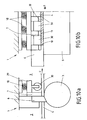
- the Figures 9a, 9b and 9c show in different views a belt lock 1 with two in the conveying direction F successively arranged lock stages.
- One of the diaphragm elements, namely the diaphragm element 9, is designed here as a roller.
- the roller 9 cooperates with three plate-shaped diaphragm elements 6, 7, 8 to define the rectangular passageway for the band 4 in the manner explained.
- Fig. 9c two guide rollers 19 arranged laterally on the belt 4 can be seen, which run on the belt edge 20 and thus center the belt 4 relative to the sealant.
- the guide rollers 19 are arranged according to this figure fixed to the aperture elements.
- the diaphragm elements 6, 7 can be aligned according to the current band edge position.
- the guide rollers 19 may also be fixedly attached to the belt lock or its base frame and guide the tape in the middle of the belt sluice.
- the aperture elements can be positioned by additional, the band contour following guide elements.
- the diaphragm elements can be biased by spring elements 18 in the direction of the belt surface in order to increase the degree of tightness.
- a cross member 29 is spring-biased by the spring elements 18, wherein the cross member 29 carries the aperture element 7.
- the traverse 29 is by means of a number of rollers 30 at a defined distance from the belt surface, whereby the position of the diaphragm element 7 is defined.
- the traverse 29 adapts via the spring bias of the spring elements 18 to the current strip contour and / or strip thickness.
- the diaphragm element 7 follows the traverse 29. In this way, a reduction of wear and thus an increase in the service life of the sealing surface 11 of the diaphragm element 7 is possible.
- the tape seal is made via laterally movable panels.
- FIG. 11a, 11b and 11c show an embodiment of the invention, are provided in the means 21 for adjusting the effective height or effective width of an aperture element.
- the panel 6 here is formed in two parts, ie it has a first panel part 6 'and a second panel part 6 " Fig. 11b shows, the two parts 6 ', 6 "formed cut at a shallow angle to the conveying direction F, ie there are contact surfaces 22 and 23, in which the parts 6', 6" are adjacent.
- a movement element 24 is schematically indicated, with which one part 6 "can be moved relative to the other part 6 'in the conveying direction F.
- the oblique course of the contact surfaces 22, 23 thus changes the effective effective height of the diaphragm 6, so that it changes Adjusting the diaphragm 6 to the thickness of the belt 4 becomes possible.
- Fig. 12 is a change means 25 outlined, with which it is possible to replace an aperture element 6 during operation.
- the aim of this embodiment of the invention is thus a change of the seal during the process or the Minimization of downtime when a panel has to be replaced due to wear.
- the panel element with the worn sealing surface can be pulled out laterally from the working area of the belt sluice.
- a new panel element can be supplied.
- the change can be carried out in particular even with existing pressure difference between the rooms 2, 3. It is both a continuous change of the diaphragm element and, if necessary, a discontinuous change possible.
- the explained change means is basically used for all aperture elements.
- a belt stabilization in the area of the belt lock 1 can take place by means of a belt deflection.
- the tape is pulled into a plane and additionally stabilized between the rollers by the bend.
- the visible formation of flatness errors and transverse arcs is reduced. This results in a reduction of the wear on the sealing elements and a reduction of the leakage.
- the pulleys 26, 27 can be used in addition to the band position control. With the band position control, the band 4 can also be moved specifically (swarming). Thus, the wear on the sealing surfaces of the diaphragm elements can be made uniform or minimized over the bandwidth. The sealing surfaces on the strip edge are tracked synchronously.
- the diaphragm elements provided according to the invention are arranged sealingly against one another and displaced in such a way that one of the cross-sectional contour of the belt results in a corresponding passageway.
- the adaptation to new tape dimensions can be done in two ways: the active adjustment is based on a controlled change in position of the diaphragm elements from; in the case of passive adaptation, the band is pressed into the required position by the sealing surfaces of the diaphragm elements.
Landscapes
- Chemical & Material Sciences (AREA)
- Organic Chemistry (AREA)
- Chemical Kinetics & Catalysis (AREA)
- Engineering & Computer Science (AREA)
- Mechanical Engineering (AREA)
- General Engineering & Computer Science (AREA)
- General Chemical & Material Sciences (AREA)
- Materials Engineering (AREA)
- Metallurgy (AREA)
- Sealing Devices (AREA)
- Sliding Valves (AREA)
- Heat Treatment Of Strip Materials And Filament Materials (AREA)
- Gasket Seals (AREA)
- Coating Apparatus (AREA)
- Advancing Webs (AREA)
- Finger-Pressure Massage (AREA)
- Control Of Motors That Do Not Use Commutators (AREA)
- Physical Vapour Deposition (AREA)
- Delivering By Means Of Belts And Rollers (AREA)
- Operating, Guiding And Securing Of Roll- Type Closing Members (AREA)
- Package Closures (AREA)
- Seal Device For Vehicle (AREA)
- Sealing Material Composition (AREA)
- Bag Frames (AREA)
- Slide Fasteners (AREA)
Priority Applications (1)
| Application Number | Priority Date | Filing Date | Title |
|---|---|---|---|
| PL07818961T PL2091642T3 (pl) | 2006-10-27 | 2007-10-12 | Śluza taśmowa |
Applications Claiming Priority (3)
| Application Number | Priority Date | Filing Date | Title |
|---|---|---|---|
| DE102006051395 | 2006-10-27 | ||
| DE102007009710A DE102007009710A1 (de) | 2006-10-27 | 2007-02-28 | Bandschleuse |
| PCT/EP2007/008890 WO2008049523A1 (de) | 2006-10-27 | 2007-10-12 | Bandschleuse |
Publications (2)
| Publication Number | Publication Date |
|---|---|
| EP2091642A1 EP2091642A1 (de) | 2009-08-26 |
| EP2091642B1 true EP2091642B1 (de) | 2010-08-18 |
Family
ID=38980918
Family Applications (1)
| Application Number | Title | Priority Date | Filing Date |
|---|---|---|---|
| EP07818961A Not-in-force EP2091642B1 (de) | 2006-10-27 | 2007-10-12 | Bandschleuse |
Country Status (14)
| Country | Link |
|---|---|
| US (1) | US20100088967A1 (ru) |
| EP (1) | EP2091642B1 (ru) |
| JP (1) | JP2010502920A (ru) |
| KR (1) | KR101005896B1 (ru) |
| AT (1) | ATE477847T1 (ru) |
| AU (1) | AU2007308439B2 (ru) |
| BR (1) | BRPI0710736A2 (ru) |
| CA (1) | CA2667501C (ru) |
| DE (2) | DE102007009710A1 (ru) |
| MX (1) | MX2008013558A (ru) |
| PL (1) | PL2091642T3 (ru) |
| RS (1) | RS52282B (ru) |
| RU (1) | RU2395332C1 (ru) |
| WO (1) | WO2008049523A1 (ru) |
Families Citing this family (5)
| Publication number | Priority date | Publication date | Assignee | Title |
|---|---|---|---|---|
| DE102007049669A1 (de) | 2007-10-17 | 2009-04-23 | Sms Demag Ag | Schleusenvorrichtung und Verfahren zum Öffnen der Schleusenvorrichtung |
| RU2761570C1 (ru) * | 2018-03-30 | 2021-12-10 | ДжФЕ СТИЛ КОРПОРЕЙШН | Оборудование для производства текстурированного листа из электротехнической стали |
| DE102018215102A1 (de) | 2018-05-28 | 2019-11-28 | Sms Group Gmbh | Vakuumbeschichtungsanlage, und Verfahren zum Beschichten eines bandförmigen Materials |
| DE102018215101A1 (de) | 2018-05-28 | 2019-11-28 | Sms Group Gmbh | Vakuumbeschichtungsanlage, und Verfahren zum Beschichten eines bandförmigen Materials |
| DE102018215100A1 (de) | 2018-05-28 | 2019-11-28 | Sms Group Gmbh | Vakuumbeschichtungsanlage, und Verfahren zum Beschichten eines bandförmigen Materials |
Family Cites Families (10)
| Publication number | Priority date | Publication date | Assignee | Title |
|---|---|---|---|---|
| US3843142A (en) * | 1972-12-20 | 1974-10-22 | Kleinewefers Ind Co Gmbh | Sealing apparatus for gas vapor container subjected to above or below atmospheric pressures for product webs to be continuously treated |
| JPS51146336A (en) * | 1975-06-11 | 1976-12-15 | Akiyoshi Yoneda | Apparatus for continuous vacuum treatment of strip material |
| JPH0325559U (ru) * | 1989-07-19 | 1991-03-15 | ||
| DE4240490C1 (de) * | 1992-12-02 | 1994-04-14 | Ardenne Anlagentech Gmbh | Dichtelement für Bandschleusen |
| JPH0657555U (ja) * | 1993-01-22 | 1994-08-09 | 住友金属工業株式会社 | チョック付き圧延ロールのサンドブラスト装置 |
| DE4418383C2 (de) * | 1994-05-26 | 1998-04-30 | Ardenne Anlagentech Gmbh | Vakuumschleuse |
| JPH09174132A (ja) * | 1995-12-25 | 1997-07-08 | Sumitomo Metal Ind Ltd | 鋼板圧延機のサイドガイド装置 |
| DE19960751A1 (de) * | 1999-12-16 | 2001-07-05 | Fzm Ges Fuer Produktentwicklun | Schleuse und Verfahren zur Anwendung derselben |
| JP2002188727A (ja) * | 2000-12-21 | 2002-07-05 | Nikku Ind Co Ltd | ローラーを使用した差圧シール装置 |
| JP4711637B2 (ja) * | 2004-03-18 | 2011-06-29 | 新日鉄エンジニアリング株式会社 | スキンパスミルのワークロール組替装置及び組替方法 |
-
2007
- 2007-02-28 DE DE102007009710A patent/DE102007009710A1/de not_active Withdrawn
- 2007-10-12 AT AT07818961T patent/ATE477847T1/de active
- 2007-10-12 CA CA2667501A patent/CA2667501C/en not_active Expired - Fee Related
- 2007-10-12 MX MX2008013558A patent/MX2008013558A/es active IP Right Grant
- 2007-10-12 EP EP07818961A patent/EP2091642B1/de not_active Not-in-force
- 2007-10-12 US US12/446,984 patent/US20100088967A1/en not_active Abandoned
- 2007-10-12 KR KR1020087023986A patent/KR101005896B1/ko not_active IP Right Cessation
- 2007-10-12 DE DE502007004823T patent/DE502007004823D1/de active Active
- 2007-10-12 RU RU2008145496/15A patent/RU2395332C1/ru not_active IP Right Cessation
- 2007-10-12 AU AU2007308439A patent/AU2007308439B2/en not_active Ceased
- 2007-10-12 PL PL07818961T patent/PL2091642T3/pl unknown
- 2007-10-12 BR BRPI0710736-6A patent/BRPI0710736A2/pt not_active IP Right Cessation
- 2007-10-12 RS RS20080500A patent/RS52282B/en unknown
- 2007-10-12 JP JP2009527071A patent/JP2010502920A/ja not_active Ceased
- 2007-10-12 WO PCT/EP2007/008890 patent/WO2008049523A1/de active Application Filing
Also Published As
| Publication number | Publication date |
|---|---|
| EP2091642A1 (de) | 2009-08-26 |
| AU2007308439B2 (en) | 2010-07-22 |
| KR101005896B1 (ko) | 2011-01-06 |
| RS52282B (en) | 2012-10-31 |
| RS20080500A (en) | 2009-05-06 |
| BRPI0710736A2 (pt) | 2011-08-09 |
| RU2395332C1 (ru) | 2010-07-27 |
| PL2091642T3 (pl) | 2011-02-28 |
| US20100088967A1 (en) | 2010-04-15 |
| CA2667501A1 (en) | 2008-05-02 |
| WO2008049523A1 (de) | 2008-05-02 |
| ATE477847T1 (de) | 2010-09-15 |
| DE502007004823D1 (de) | 2010-09-30 |
| RU2008145496A (ru) | 2010-05-27 |
| AU2007308439A1 (en) | 2008-05-02 |
| CA2667501C (en) | 2012-01-17 |
| KR20090003293A (ko) | 2009-01-09 |
| DE102007009710A1 (de) | 2008-04-30 |
| MX2008013558A (es) | 2008-11-04 |
| JP2010502920A (ja) | 2010-01-28 |
Similar Documents
| Publication | Publication Date | Title |
|---|---|---|
| EP2215387B1 (de) | Vakuumventil | |
| DE602004001655T2 (de) | Unterdruck-Bandförderer für plattenartige Teile | |
| DE102010053411B4 (de) | Vakuumventil | |
| DE2345832A1 (de) | Kontinuierlich arbeitende presse | |
| EP2091642B1 (de) | Bandschleuse | |
| EP0026401A1 (de) | Vorrichtung zum Aufbringen einer Flächenpressung auf fortschreitende Werkstücke | |
| DE2937971C2 (ru) | ||
| DE69824295T3 (de) | Abgedichtete Schleuse für eine Vakuumkammer | |
| DE202004005216U1 (de) | Umsetzbares Wartungsventil | |
| WO2010115917A1 (de) | Vakuumventil und vakuumkammersystem | |
| DE602004001403T2 (de) | Abgedichtete schleuse für eine in-line vakuumbeschichtungsanlage | |
| EP2089145B1 (de) | Bandschleuse | |
| DE102013106026A1 (de) | Vakuumanordnung und Verfahren zum Betreiben einer Vakuumanordnung | |
| DE102006035647A1 (de) | Vorrichtung zum Herstellen oder/und Bearbeiten von Paneelen | |
| DE3050419C2 (de) | Vakuumkammer f}r einen Teilchenbeschleuniger | |
| DE102018118212B3 (de) | Gleitflächendichtung für eine kontinuierlich arbeitende Doppelbandpresse und Doppelbandpresse | |
| WO2011072315A1 (de) | Vakuumventil | |
| AT514196B1 (de) | Walzenanordnung mit einem bewegbaren Einlaufschild | |
| EP2089146A1 (de) | Bandschleuse | |
| DE19845652C2 (de) | Vorrichtung zum Glätten und Kühlen bzw. Kühlen einer extrudierten Materialbahn | |
| DE60201747T2 (de) | Vorrichtung zum eintragen von weichelastischen bändern in eine kammer | |
| EP0535439A1 (de) | Schleusenvorrichtung für das Ein- und/oder Ausführen von bandförmigem Material in/aus dampf- oder gasgefüllte(n) Behälter(n) | |
| DE3022691A1 (de) | Arrondiervorrichtung fuer scharfkantige bandraender | |
| DE2121406C3 (de) | Vorrichtung zum Elektronenstrahlschweißen | |
| AT513812B1 (de) | Förderer mit mindestens einem endlos umlaufenden Zugmittel |
Legal Events
| Date | Code | Title | Description |
|---|---|---|---|
| PUAI | Public reference made under article 153(3) epc to a published international application that has entered the european phase |
Free format text: ORIGINAL CODE: 0009012 |
|
| 17P | Request for examination filed |
Effective date: 20080806 |
|
| AK | Designated contracting states |
Kind code of ref document: A1 Designated state(s): AT BE BG CH CY CZ DE DK EE ES FI FR GB GR HU IE IS IT LI LT LU LV MC MT NL PL PT RO SE SI SK TR |
|
| DAX | Request for extension of the european patent (deleted) | ||
| GRAP | Despatch of communication of intention to grant a patent |
Free format text: ORIGINAL CODE: EPIDOSNIGR1 |
|
| GRAS | Grant fee paid |
Free format text: ORIGINAL CODE: EPIDOSNIGR3 |
|
| GRAA | (expected) grant |
Free format text: ORIGINAL CODE: 0009210 |
|
| AK | Designated contracting states |
Kind code of ref document: B1 Designated state(s): AT BE BG CH CY CZ DE DK EE ES FI FR GB GR HU IE IS IT LI LT LU LV MC MT NL PL PT RO SE SI SK TR |
|
| REG | Reference to a national code |
Ref country code: GB Ref legal event code: FG4D Free format text: NOT ENGLISH |
|
| REG | Reference to a national code |
Ref country code: CH Ref legal event code: EP |
|
| REG | Reference to a national code |
Ref country code: IE Ref legal event code: FG4D Free format text: LANGUAGE OF EP DOCUMENT: GERMAN |
|
| REF | Corresponds to: |
Ref document number: 502007004823 Country of ref document: DE Date of ref document: 20100930 Kind code of ref document: P |
|
| REG | Reference to a national code |
Ref country code: SE Ref legal event code: TRGR |
|
| REG | Reference to a national code |
Ref country code: NL Ref legal event code: T3 |
|
| REG | Reference to a national code |
Ref country code: SK Ref legal event code: T3 Ref document number: E 8109 Country of ref document: SK |
|
| LTIE | Lt: invalidation of european patent or patent extension |
Effective date: 20100818 |
|
| REG | Reference to a national code |
Ref country code: ES Ref legal event code: FG2A Effective date: 20110117 |
|
| PG25 | Lapsed in a contracting state [announced via postgrant information from national office to epo] |
Ref country code: LT Free format text: LAPSE BECAUSE OF FAILURE TO SUBMIT A TRANSLATION OF THE DESCRIPTION OR TO PAY THE FEE WITHIN THE PRESCRIBED TIME-LIMIT Effective date: 20100818 |
|
| PG25 | Lapsed in a contracting state [announced via postgrant information from national office to epo] |
Ref country code: BG Free format text: LAPSE BECAUSE OF FAILURE TO SUBMIT A TRANSLATION OF THE DESCRIPTION OR TO PAY THE FEE WITHIN THE PRESCRIBED TIME-LIMIT Effective date: 20101118 Ref country code: CY Free format text: LAPSE BECAUSE OF FAILURE TO SUBMIT A TRANSLATION OF THE DESCRIPTION OR TO PAY THE FEE WITHIN THE PRESCRIBED TIME-LIMIT Effective date: 20100818 Ref country code: IS Free format text: LAPSE BECAUSE OF FAILURE TO SUBMIT A TRANSLATION OF THE DESCRIPTION OR TO PAY THE FEE WITHIN THE PRESCRIBED TIME-LIMIT Effective date: 20101218 Ref country code: PT Free format text: LAPSE BECAUSE OF FAILURE TO SUBMIT A TRANSLATION OF THE DESCRIPTION OR TO PAY THE FEE WITHIN THE PRESCRIBED TIME-LIMIT Effective date: 20101220 Ref country code: SI Free format text: LAPSE BECAUSE OF FAILURE TO SUBMIT A TRANSLATION OF THE DESCRIPTION OR TO PAY THE FEE WITHIN THE PRESCRIBED TIME-LIMIT Effective date: 20100818 |
|
| PGFP | Annual fee paid to national office [announced via postgrant information from national office to epo] |
Ref country code: SK Payment date: 20101011 Year of fee payment: 4 |
|
| REG | Reference to a national code |
Ref country code: PL Ref legal event code: T3 |
|
| REG | Reference to a national code |
Ref country code: IE Ref legal event code: FD4D |
|
| PG25 | Lapsed in a contracting state [announced via postgrant information from national office to epo] |
Ref country code: LV Free format text: LAPSE BECAUSE OF FAILURE TO SUBMIT A TRANSLATION OF THE DESCRIPTION OR TO PAY THE FEE WITHIN THE PRESCRIBED TIME-LIMIT Effective date: 20100818 Ref country code: GR Free format text: LAPSE BECAUSE OF FAILURE TO SUBMIT A TRANSLATION OF THE DESCRIPTION OR TO PAY THE FEE WITHIN THE PRESCRIBED TIME-LIMIT Effective date: 20101119 |
|
| PG25 | Lapsed in a contracting state [announced via postgrant information from national office to epo] |
Ref country code: IE Free format text: LAPSE BECAUSE OF FAILURE TO SUBMIT A TRANSLATION OF THE DESCRIPTION OR TO PAY THE FEE WITHIN THE PRESCRIBED TIME-LIMIT Effective date: 20100818 Ref country code: DK Free format text: LAPSE BECAUSE OF FAILURE TO SUBMIT A TRANSLATION OF THE DESCRIPTION OR TO PAY THE FEE WITHIN THE PRESCRIBED TIME-LIMIT Effective date: 20100818 |
|
| PG25 | Lapsed in a contracting state [announced via postgrant information from national office to epo] |
Ref country code: MC Free format text: LAPSE BECAUSE OF NON-PAYMENT OF DUE FEES Effective date: 20101031 Ref country code: EE Free format text: LAPSE BECAUSE OF FAILURE TO SUBMIT A TRANSLATION OF THE DESCRIPTION OR TO PAY THE FEE WITHIN THE PRESCRIBED TIME-LIMIT Effective date: 20100818 Ref country code: RO Free format text: LAPSE BECAUSE OF FAILURE TO SUBMIT A TRANSLATION OF THE DESCRIPTION OR TO PAY THE FEE WITHIN THE PRESCRIBED TIME-LIMIT Effective date: 20100818 Ref country code: CZ Free format text: LAPSE BECAUSE OF FAILURE TO SUBMIT A TRANSLATION OF THE DESCRIPTION OR TO PAY THE FEE WITHIN THE PRESCRIBED TIME-LIMIT Effective date: 20100818 |
|
| PGFP | Annual fee paid to national office [announced via postgrant information from national office to epo] |
Ref country code: PL Payment date: 20101007 Year of fee payment: 4 |
|
| PLBE | No opposition filed within time limit |
Free format text: ORIGINAL CODE: 0009261 |
|
| STAA | Information on the status of an ep patent application or granted ep patent |
Free format text: STATUS: NO OPPOSITION FILED WITHIN TIME LIMIT |
|
| 26N | No opposition filed |
Effective date: 20110519 |
|
| REG | Reference to a national code |
Ref country code: DE Ref legal event code: R097 Ref document number: 502007004823 Country of ref document: DE Effective date: 20110519 |
|
| PGFP | Annual fee paid to national office [announced via postgrant information from national office to epo] |
Ref country code: TR Payment date: 20110927 Year of fee payment: 5 |
|
| PG25 | Lapsed in a contracting state [announced via postgrant information from national office to epo] |
Ref country code: IT Free format text: LAPSE BECAUSE OF NON-PAYMENT OF DUE FEES Effective date: 20101012 Ref country code: MT Free format text: LAPSE BECAUSE OF FAILURE TO SUBMIT A TRANSLATION OF THE DESCRIPTION OR TO PAY THE FEE WITHIN THE PRESCRIBED TIME-LIMIT Effective date: 20100818 |
|
| PGFP | Annual fee paid to national office [announced via postgrant information from national office to epo] |
Ref country code: SE Payment date: 20111021 Year of fee payment: 5 Ref country code: NL Payment date: 20111025 Year of fee payment: 5 Ref country code: LU Payment date: 20111024 Year of fee payment: 5 Ref country code: FI Payment date: 20111013 Year of fee payment: 5 Ref country code: ES Payment date: 20111026 Year of fee payment: 5 |
|
| REG | Reference to a national code |
Ref country code: CH Ref legal event code: PL |
|
| PG25 | Lapsed in a contracting state [announced via postgrant information from national office to epo] |
Ref country code: CH Free format text: LAPSE BECAUSE OF NON-PAYMENT OF DUE FEES Effective date: 20111031 Ref country code: LI Free format text: LAPSE BECAUSE OF NON-PAYMENT OF DUE FEES Effective date: 20111031 |
|
| PG25 | Lapsed in a contracting state [announced via postgrant information from national office to epo] |
Ref country code: HU Free format text: LAPSE BECAUSE OF FAILURE TO SUBMIT A TRANSLATION OF THE DESCRIPTION OR TO PAY THE FEE WITHIN THE PRESCRIBED TIME-LIMIT Effective date: 20110219 |
|
| PGFP | Annual fee paid to national office [announced via postgrant information from national office to epo] |
Ref country code: FR Payment date: 20121031 Year of fee payment: 6 Ref country code: BE Payment date: 20121022 Year of fee payment: 6 |
|
| PGFP | Annual fee paid to national office [announced via postgrant information from national office to epo] |
Ref country code: IT Payment date: 20121023 Year of fee payment: 6 |
|
| PGFP | Annual fee paid to national office [announced via postgrant information from national office to epo] |
Ref country code: AT Payment date: 20121011 Year of fee payment: 6 |
|
| REG | Reference to a national code |
Ref country code: NL Ref legal event code: V1 Effective date: 20130501 |
|
| GBPC | Gb: european patent ceased through non-payment of renewal fee |
Effective date: 20121012 |
|
| REG | Reference to a national code |
Ref country code: SK Ref legal event code: MM4A Ref document number: E 8109 Country of ref document: SK Effective date: 20121012 |
|
| PG25 | Lapsed in a contracting state [announced via postgrant information from national office to epo] |
Ref country code: GB Free format text: LAPSE BECAUSE OF NON-PAYMENT OF DUE FEES Effective date: 20121012 Ref country code: SK Free format text: LAPSE BECAUSE OF NON-PAYMENT OF DUE FEES Effective date: 20121012 Ref country code: SE Free format text: LAPSE BECAUSE OF NON-PAYMENT OF DUE FEES Effective date: 20121013 |
|
| PG25 | Lapsed in a contracting state [announced via postgrant information from national office to epo] |
Ref country code: FI Free format text: LAPSE BECAUSE OF NON-PAYMENT OF DUE FEES Effective date: 20121012 Ref country code: NL Free format text: LAPSE BECAUSE OF NON-PAYMENT OF DUE FEES Effective date: 20130501 |
|
| REG | Reference to a national code |
Ref country code: ES Ref legal event code: FD2A Effective date: 20140115 |
|
| PG25 | Lapsed in a contracting state [announced via postgrant information from national office to epo] |
Ref country code: PL Free format text: LAPSE BECAUSE OF NON-PAYMENT OF DUE FEES Effective date: 20121012 Ref country code: ES Free format text: LAPSE BECAUSE OF NON-PAYMENT OF DUE FEES Effective date: 20121013 |
|
| BERE | Be: lapsed |
Owner name: SMS SIEMAG AG Effective date: 20131031 |
|
| PGFP | Annual fee paid to national office [announced via postgrant information from national office to epo] |
Ref country code: DE Payment date: 20140214 Year of fee payment: 7 |
|
| REG | Reference to a national code |
Ref country code: DE Ref legal event code: R119 Ref document number: 502007004823 Country of ref document: DE |
|
| PG25 | Lapsed in a contracting state [announced via postgrant information from national office to epo] |
Ref country code: LU Free format text: LAPSE BECAUSE OF NON-PAYMENT OF DUE FEES Effective date: 20121012 Ref country code: TR Free format text: LAPSE BECAUSE OF NON-PAYMENT OF DUE FEES Effective date: 20121012 |
|
| REG | Reference to a national code |
Ref country code: AT Ref legal event code: MM01 Ref document number: 477847 Country of ref document: AT Kind code of ref document: T Effective date: 20131012 |
|
| REG | Reference to a national code |
Ref country code: FR Ref legal event code: ST Effective date: 20140630 |
|
| PG25 | Lapsed in a contracting state [announced via postgrant information from national office to epo] |
Ref country code: FR Free format text: LAPSE BECAUSE OF NON-PAYMENT OF DUE FEES Effective date: 20131031 Ref country code: IT Free format text: LAPSE BECAUSE OF NON-PAYMENT OF DUE FEES Effective date: 20131012 Ref country code: AT Free format text: LAPSE BECAUSE OF NON-PAYMENT OF DUE FEES Effective date: 20131012 |
|
| PG25 | Lapsed in a contracting state [announced via postgrant information from national office to epo] |
Ref country code: BE Free format text: LAPSE BECAUSE OF NON-PAYMENT OF DUE FEES Effective date: 20131031 |
|
| PG25 | Lapsed in a contracting state [announced via postgrant information from national office to epo] |
Ref country code: DE Free format text: LAPSE BECAUSE OF NON-PAYMENT OF DUE FEES Effective date: 20140501 |
|
| REG | Reference to a national code |
Ref country code: DE Ref legal event code: R119 Ref document number: 502007004823 Country of ref document: DE Effective date: 20140501 |