EP2090912A1 - Faseroptische Auskoppelkabel und vorverbundene Baugruppen mit Toning-Teilen - Google Patents
Faseroptische Auskoppelkabel und vorverbundene Baugruppen mit Toning-Teilen Download PDFInfo
- Publication number
- EP2090912A1 EP2090912A1 EP09003586A EP09003586A EP2090912A1 EP 2090912 A1 EP2090912 A1 EP 2090912A1 EP 09003586 A EP09003586 A EP 09003586A EP 09003586 A EP09003586 A EP 09003586A EP 2090912 A1 EP2090912 A1 EP 2090912A1
- Authority
- EP
- European Patent Office
- Prior art keywords
- cable
- housing
- plug connector
- preconnectorized
- optical waveguide
- Prior art date
- Legal status (The legal status is an assumption and is not a legal conclusion. Google has not performed a legal analysis and makes no representation as to the accuracy of the status listed.)
- Withdrawn
Links
- 239000000835 fiber Substances 0.000 title description 22
- 230000000712 assembly Effects 0.000 title description 4
- 238000000429 assembly Methods 0.000 title description 4
- 230000003287 optical effect Effects 0.000 claims abstract description 81
- 230000013011 mating Effects 0.000 claims abstract description 11
- 230000008878 coupling Effects 0.000 claims description 15
- 238000010168 coupling process Methods 0.000 claims description 15
- 238000005859 coupling reaction Methods 0.000 claims description 15
- 230000001681 protective effect Effects 0.000 claims description 14
- 239000000463 material Substances 0.000 claims description 7
- 239000004593 Epoxy Substances 0.000 claims description 4
- 239000000853 adhesive Substances 0.000 claims description 4
- 230000001070 adhesive effect Effects 0.000 claims description 4
- 230000000295 complement effect Effects 0.000 abstract description 9
- 238000013461 design Methods 0.000 description 13
- RYGMFSIKBFXOCR-UHFFFAOYSA-N Copper Chemical compound [Cu] RYGMFSIKBFXOCR-UHFFFAOYSA-N 0.000 description 12
- 229910052802 copper Inorganic materials 0.000 description 12
- 239000010949 copper Substances 0.000 description 12
- 238000004891 communication Methods 0.000 description 11
- 238000000034 method Methods 0.000 description 7
- 239000013307 optical fiber Substances 0.000 description 5
- 239000004020 conductor Substances 0.000 description 4
- 238000007526 fusion splicing Methods 0.000 description 3
- 229920000642 polymer Polymers 0.000 description 3
- 239000011230 binding agent Substances 0.000 description 2
- 239000011152 fibreglass Substances 0.000 description 2
- 230000002401 inhibitory effect Effects 0.000 description 2
- 238000003780 insertion Methods 0.000 description 2
- 230000037431 insertion Effects 0.000 description 2
- 238000012986 modification Methods 0.000 description 2
- 230000004048 modification Effects 0.000 description 2
- 238000005498 polishing Methods 0.000 description 2
- 238000012360 testing method Methods 0.000 description 2
- 238000012549 training Methods 0.000 description 2
- 229910001369 Brass Inorganic materials 0.000 description 1
- 229910000831 Steel Inorganic materials 0.000 description 1
- 229920004773 ULTEM® 2210 Polymers 0.000 description 1
- 239000004760 aramid Substances 0.000 description 1
- 229920006231 aramid fiber Polymers 0.000 description 1
- 238000005452 bending Methods 0.000 description 1
- 230000005540 biological transmission Effects 0.000 description 1
- 239000010951 brass Substances 0.000 description 1
- 150000001875 compounds Chemical class 0.000 description 1
- 238000002788 crimping Methods 0.000 description 1
- KAATUXNTWXVJKI-UHFFFAOYSA-N cypermethrin Chemical compound CC1(C)C(C=C(Cl)Cl)C1C(=O)OC(C#N)C1=CC=CC(OC=2C=CC=CC=2)=C1 KAATUXNTWXVJKI-UHFFFAOYSA-N 0.000 description 1
- 239000003989 dielectric material Substances 0.000 description 1
- 210000005069 ears Anatomy 0.000 description 1
- 238000001125 extrusion Methods 0.000 description 1
- 238000007689 inspection Methods 0.000 description 1
- 238000009434 installation Methods 0.000 description 1
- 230000014759 maintenance of location Effects 0.000 description 1
- 239000002184 metal Substances 0.000 description 1
- 229910052751 metal Inorganic materials 0.000 description 1
- NJPPVKZQTLUDBO-UHFFFAOYSA-N novaluron Chemical compound C1=C(Cl)C(OC(F)(F)C(OC(F)(F)F)F)=CC=C1NC(=O)NC(=O)C1=C(F)C=CC=C1F NJPPVKZQTLUDBO-UHFFFAOYSA-N 0.000 description 1
- 239000004033 plastic Substances 0.000 description 1
- 229920003023 plastic Polymers 0.000 description 1
- 239000000843 powder Substances 0.000 description 1
- 229910001220 stainless steel Inorganic materials 0.000 description 1
- 239000010935 stainless steel Substances 0.000 description 1
- 239000010959 steel Substances 0.000 description 1
- 238000012546 transfer Methods 0.000 description 1
- XLYOFNOQVPJJNP-UHFFFAOYSA-N water Substances O XLYOFNOQVPJJNP-UHFFFAOYSA-N 0.000 description 1
Images


Classifications
-
- G—PHYSICS
- G02—OPTICS
- G02B—OPTICAL ELEMENTS, SYSTEMS OR APPARATUS
- G02B6/00—Light guides; Structural details of arrangements comprising light guides and other optical elements, e.g. couplings
- G02B6/46—Processes or apparatus adapted for installing or repairing optical fibres or optical cables
- G02B6/56—Processes for repairing optical cables
- G02B6/562—Processes for repairing optical cables locatable, e.g. using magnetic means
-
- G—PHYSICS
- G02—OPTICS
- G02B—OPTICAL ELEMENTS, SYSTEMS OR APPARATUS
- G02B6/00—Light guides; Structural details of arrangements comprising light guides and other optical elements, e.g. couplings
- G02B6/24—Coupling light guides
- G02B6/36—Mechanical coupling means
- G02B6/38—Mechanical coupling means having fibre to fibre mating means
- G02B6/3807—Dismountable connectors, i.e. comprising plugs
- G02B6/3833—Details of mounting fibres in ferrules; Assembly methods; Manufacture
- G02B6/3847—Details of mounting fibres in ferrules; Assembly methods; Manufacture with means preventing fibre end damage, e.g. recessed fibre surfaces
- G02B6/3849—Details of mounting fibres in ferrules; Assembly methods; Manufacture with means preventing fibre end damage, e.g. recessed fibre surfaces using mechanical protective elements, e.g. caps, hoods, sealing membranes
-
- G—PHYSICS
- G02—OPTICS
- G02B—OPTICAL ELEMENTS, SYSTEMS OR APPARATUS
- G02B6/00—Light guides; Structural details of arrangements comprising light guides and other optical elements, e.g. couplings
- G02B6/24—Coupling light guides
- G02B6/36—Mechanical coupling means
- G02B6/38—Mechanical coupling means having fibre to fibre mating means
- G02B6/3807—Dismountable connectors, i.e. comprising plugs
- G02B6/3869—Mounting ferrules to connector body, i.e. plugs
-
- G—PHYSICS
- G02—OPTICS
- G02B—OPTICAL ELEMENTS, SYSTEMS OR APPARATUS
- G02B6/00—Light guides; Structural details of arrangements comprising light guides and other optical elements, e.g. couplings
- G02B6/24—Coupling light guides
- G02B6/36—Mechanical coupling means
- G02B6/38—Mechanical coupling means having fibre to fibre mating means
- G02B6/3807—Dismountable connectors, i.e. comprising plugs
- G02B6/3887—Anchoring optical cables to connector housings, e.g. strain relief features
- G02B6/3889—Anchoring optical cables to connector housings, e.g. strain relief features using encapsulation for protection, e.g. adhesive, molding or casting resin
-
- G—PHYSICS
- G02—OPTICS
- G02B—OPTICAL ELEMENTS, SYSTEMS OR APPARATUS
- G02B6/00—Light guides; Structural details of arrangements comprising light guides and other optical elements, e.g. couplings
- G02B6/24—Coupling light guides
- G02B6/36—Mechanical coupling means
- G02B6/38—Mechanical coupling means having fibre to fibre mating means
- G02B6/3807—Dismountable connectors, i.e. comprising plugs
- G02B6/389—Dismountable connectors, i.e. comprising plugs characterised by the method of fastening connecting plugs and sockets, e.g. screw- or nut-lock, snap-in, bayonet type
- G02B6/3894—Screw-lock type
-
- G—PHYSICS
- G02—OPTICS
- G02B—OPTICAL ELEMENTS, SYSTEMS OR APPARATUS
- G02B6/00—Light guides; Structural details of arrangements comprising light guides and other optical elements, e.g. couplings
- G02B6/24—Coupling light guides
- G02B6/36—Mechanical coupling means
- G02B6/38—Mechanical coupling means having fibre to fibre mating means
- G02B6/3807—Dismountable connectors, i.e. comprising plugs
- G02B6/3897—Connectors fixed to housings, casing, frames or circuit boards
-
- G—PHYSICS
- G02—OPTICS
- G02B—OPTICAL ELEMENTS, SYSTEMS OR APPARATUS
- G02B6/00—Light guides; Structural details of arrangements comprising light guides and other optical elements, e.g. couplings
- G02B6/44—Mechanical structures for providing tensile strength and external protection for fibres, e.g. optical transmission cables
- G02B6/4401—Optical cables
- G02B6/4405—Optical cables with longitudinally spaced waveguide clamping
-
- G—PHYSICS
- G02—OPTICS
- G02B—OPTICAL ELEMENTS, SYSTEMS OR APPARATUS
- G02B6/00—Light guides; Structural details of arrangements comprising light guides and other optical elements, e.g. couplings
- G02B6/44—Mechanical structures for providing tensile strength and external protection for fibres, e.g. optical transmission cables
- G02B6/4401—Optical cables
- G02B6/4429—Means specially adapted for strengthening or protecting the cables
- G02B6/443—Protective covering
- G02B6/4432—Protective covering with fibre reinforcements
- G02B6/4433—Double reinforcement laying in straight line with optical transmission element
-
- G—PHYSICS
- G02—OPTICS
- G02B—OPTICAL ELEMENTS, SYSTEMS OR APPARATUS
- G02B6/00—Light guides; Structural details of arrangements comprising light guides and other optical elements, e.g. couplings
- G02B6/44—Mechanical structures for providing tensile strength and external protection for fibres, e.g. optical transmission cables
- G02B6/4439—Auxiliary devices
- G02B6/4471—Terminating devices ; Cable clamps
- G02B6/44785—Cable clamps
-
- G—PHYSICS
- G02—OPTICS
- G02B—OPTICAL ELEMENTS, SYSTEMS OR APPARATUS
- G02B6/00—Light guides; Structural details of arrangements comprising light guides and other optical elements, e.g. couplings
- G02B6/24—Coupling light guides
- G02B6/36—Mechanical coupling means
- G02B6/38—Mechanical coupling means having fibre to fibre mating means
- G02B6/3807—Dismountable connectors, i.e. comprising plugs
- G02B6/381—Dismountable connectors, i.e. comprising plugs of the ferrule type, e.g. fibre ends embedded in ferrules, connecting a pair of fibres
- G02B6/3816—Dismountable connectors, i.e. comprising plugs of the ferrule type, e.g. fibre ends embedded in ferrules, connecting a pair of fibres for use under water, high pressure connectors
-
- G—PHYSICS
- G02—OPTICS
- G02B—OPTICAL ELEMENTS, SYSTEMS OR APPARATUS
- G02B6/00—Light guides; Structural details of arrangements comprising light guides and other optical elements, e.g. couplings
- G02B6/24—Coupling light guides
- G02B6/36—Mechanical coupling means
- G02B6/38—Mechanical coupling means having fibre to fibre mating means
- G02B6/3807—Dismountable connectors, i.e. comprising plugs
- G02B6/381—Dismountable connectors, i.e. comprising plugs of the ferrule type, e.g. fibre ends embedded in ferrules, connecting a pair of fibres
- G02B6/3818—Dismountable connectors, i.e. comprising plugs of the ferrule type, e.g. fibre ends embedded in ferrules, connecting a pair of fibres of a low-reflection-loss type
- G02B6/3821—Dismountable connectors, i.e. comprising plugs of the ferrule type, e.g. fibre ends embedded in ferrules, connecting a pair of fibres of a low-reflection-loss type with axial spring biasing or loading means
-
- G—PHYSICS
- G02—OPTICS
- G02B—OPTICAL ELEMENTS, SYSTEMS OR APPARATUS
- G02B6/00—Light guides; Structural details of arrangements comprising light guides and other optical elements, e.g. couplings
- G02B6/24—Coupling light guides
- G02B6/36—Mechanical coupling means
- G02B6/38—Mechanical coupling means having fibre to fibre mating means
- G02B6/3807—Dismountable connectors, i.e. comprising plugs
- G02B6/3869—Mounting ferrules to connector body, i.e. plugs
- G02B6/387—Connector plugs comprising two complementary members, e.g. shells, caps, covers, locked together
-
- G—PHYSICS
- G02—OPTICS
- G02B—OPTICAL ELEMENTS, SYSTEMS OR APPARATUS
- G02B6/00—Light guides; Structural details of arrangements comprising light guides and other optical elements, e.g. couplings
- G02B6/24—Coupling light guides
- G02B6/36—Mechanical coupling means
- G02B6/38—Mechanical coupling means having fibre to fibre mating means
- G02B6/3807—Dismountable connectors, i.e. comprising plugs
- G02B6/3873—Connectors using guide surfaces for aligning ferrule ends, e.g. tubes, sleeves, V-grooves, rods, pins, balls
- G02B6/3874—Connectors using guide surfaces for aligning ferrule ends, e.g. tubes, sleeves, V-grooves, rods, pins, balls using tubes, sleeves to align ferrules
- G02B6/3878—Connectors using guide surfaces for aligning ferrule ends, e.g. tubes, sleeves, V-grooves, rods, pins, balls using tubes, sleeves to align ferrules comprising a plurality of ferrules, branching and break-out means
- G02B6/3879—Linking of individual connector plugs to an overconnector, e.g. using clamps, clips, common housings comprising several individual connector plugs
-
- G—PHYSICS
- G02—OPTICS
- G02B—OPTICAL ELEMENTS, SYSTEMS OR APPARATUS
- G02B6/00—Light guides; Structural details of arrangements comprising light guides and other optical elements, e.g. couplings
- G02B6/24—Coupling light guides
- G02B6/36—Mechanical coupling means
- G02B6/38—Mechanical coupling means having fibre to fibre mating means
- G02B6/3807—Dismountable connectors, i.e. comprising plugs
- G02B6/3873—Connectors using guide surfaces for aligning ferrule ends, e.g. tubes, sleeves, V-grooves, rods, pins, balls
- G02B6/3885—Multicore or multichannel optical connectors, i.e. one single ferrule containing more than one fibre, e.g. ribbon type
-
- G—PHYSICS
- G02—OPTICS
- G02B—OPTICAL ELEMENTS, SYSTEMS OR APPARATUS
- G02B6/00—Light guides; Structural details of arrangements comprising light guides and other optical elements, e.g. couplings
- G02B6/24—Coupling light guides
- G02B6/36—Mechanical coupling means
- G02B6/38—Mechanical coupling means having fibre to fibre mating means
- G02B6/3807—Dismountable connectors, i.e. comprising plugs
- G02B6/3887—Anchoring optical cables to connector housings, e.g. strain relief features
- G02B6/38875—Protection from bending or twisting
Definitions
- 10/765,434 , 10/765,262 , and 10/765,428 are also Continuation-in-Parts of co-pending U.S. Serial No. 10/659,666 filed on Sept. 10, 2003 , which is a Divisional of U.S. Serial No. 09/967,259 filed on Sept. 28, 2001 now U.S. Pat. No. 6,648,520 and Continuation-in-Parts of U.S. Serial No. 10/383,468 filed on March 7, 2003 now U.S. Pat. No. 6,785,450 , which is a Continuation of U.S. Serial No. 09/579,555 filed on May 26, 2000 now U.S. Pat. No. 6,546,175 .
- the present invention relates generally to optical cables and networks. More specifically, the invention relates to preconnectorized fiber optic drop cables and assemblies useful for optical networks that bring fiber to the 'x' location (FTTx) and the like.
- FTTx 'x' location
- Communication networks are used to transport a variety of signals such as voice, video, data transmission, and the like.
- Traditional communication networks use copper wires in cables for transporting information and data.
- copper cables have drawbacks because they are large, heavy, and can only transmit a relatively limited amount of data.
- an optical waveguide is capable of transmitting an extremely large amount of bandwidth compared with a copper conductor.
- an optical waveguide cable is much lighter and smaller compared with a copper cable having the same bandwidth capacity. Consequently, optical waveguide cables replaced most of the copper cables in long-haul communication network links, thereby providing greater bandwidth capacity for long-haul links.
- many of these long-haul links have bandwidth capacity that is not being used.
- optical waveguides are deployed deeper into communication networks, subscribers will have access to increased bandwidth. But there are certain obstacles that make it challenging and/or expensive to route optical waveguides/optical cables deeper into the communication network, i.e., closer to the subscriber. For instance, making a suitable optical connection between optical waveguides is much more difficult than making an electrical connection between copper wires. This is because optical connections require special tools and equipment, highly trained craftsman, along with precision components. Additionally, as the communication network pushes toward subscribers, the communication network requires more connections, which compounds the difficulties of providing optical waveguides to the premises of the subscriber. Hence, the routing of optical waveguides to the proverbial last mile of the network has yet to enjoy commercial success.
- Optical connectors generally hold the mating optical waveguides in respective ferrules of the mating connectors.
- the ferrules and optical waveguides therein require polishing of the end face for proper operation. Polishing a ferrule is a relatively complex process that generally requires several steps along with inspection and testing using precision equipment to verify an acceptable insertion loss. In other words, installing connectors is best performed in a factory setting under ideal working conditions.
- Fusion splicing requires that the ends of the optical fibers be precisely aligned so that the transfer the optical signal between the ends of the optical waveguides has a relatively low-loss. But like connectors, fusion splicing requires highly trained craftsman and special equipment to make and test the optical connection, thereby making it a relatively expensive and inefficient proposition for field connectorization. Thus, there is need for an efficient and relatively low-cost method of reliably making optical connections in the field without using specialized equipment and highly skilled labor.
- Fig. 1 schematically depicts a portion of an optical waveguide network 1 in an exemplary fiber to the location 'x' (FTTx).
- 'x' in the acronym represents the end location of the optical waveguide, for instance, FTTC is fiber to the curb.
- network 1 is a fiber to the premises (FTTP) application.
- FTTP architectures advantageously route at least one optical waveguide to the premises, thereby providing a high bandwidth connection to the subscriber. Applications to locations other than to the curb or premises are also possible.
- Downstream from a central office CO network 1 includes a feeder link 2, a first 1:N splitter 3, a distribution link 4, a second 1:M splitter 5, and at least one drop link 6.
- drop link 6 comprises a preconnectorized fiber optic drop cable 10 (hereinafter preconnectorized cable) suitable for outdoor environments.
- Preconnectorized cable 10 effectively and economically streamlines the deployment and installation of optical waveguides into the last mile of the fiber optic network such as to the premises.
- network 1 shows a simple configuration of one type of FTTx architecture
- Other networks may include other suitable components such as distribution closures, amplifiers, couplers, transducers, or the like.
- other networks besides FTTx architectures can also benefit from the concepts of the present invention.
- Fig. 2 schematically illustrates two preconnectorized cables 10 and 10' being routed to a premises 20 using different exemplary techniques.
- Fig. 2 shows first preconnectorized cable 10 being routed to premises 20 in an aerial application and second preconnectorized cable 10' being routed to premise 20 in a buried application.
- a first end 10a of preconnectorized cable 10 is attached at a first interface device 12 located on pole 11 and a second end 10b of preconnectorized cable 10 is attached at interface device 14 located at the subscriber premises 20.
- the first and second ends of preconnectorized cable 10' are respectively connected to interface device 16 located inside pedestal 18 and interface device 14.
- the interface devices include at least one receptacle 30 for making the optical connection with an end of preconnectorized cable 10.
- Figs. 3a-c show the various stages during the mating of an end of preconnectorized cable 10 with receptacle 30.
- Fig. 3a shows receptacle 30 detached from preconnectorized cable 10.
- preconnectorized cable 10 and receptacle 30 are depicted with their respective protective caps on.
- Protective cap 68 is used for shielding a connector assembly 52, and in particular, the end face of a connector ferrule 52b from the elements and/or damage.
- installed protective cap 68 isolates connector ferrule 52b from the elements and prevents it from being damaged during transportation and handling.
- Fig. 3b shows protective cap 68 removed from the end of preconnectorized cable 10.
- Preconnectorized cable 10 is positioned to engage the complimentary portions of receptacle 30.
- an alignment indicia 60c of preconnectorized cable 10 is positioned to its complementary indicia 30c of receptacle 30.
- Fig. 3c shows a mated connection between the preconnectorized cable 10 and receptacle 30, thereby making an optical connection therebetween.
- no special equipment, training, or skill is required to make the optical connection.
- the labor cost of deploying the optical network to the premises is cost effective and efficient.
- the mating between the plug connector and the receptacle is secured using a threaded engagement, but other suitable means of securing the optical connection are possible.
- the securing means may use a quarter-turn lock, a quick release, a push-pull latch, or a bayonet configuration.
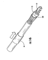
- Fig. 4 depicts a perspective view of an assembled preconnectorized cable 10 having an optional toning portion.
- Preconnectorized cable 10 includes a fiber optic cable 40 (hereinafter cable 40) and an optical plug connector 50 mounted upon one end of cable 40.
- cable 40 is a flat dielectric cable having a toning portion that is configured as a toning lobe 41 connected by a web portion. As shown, a portion of toning lobe 41 is separated and coiled before optical plug connector 50, thereby keeping it out of way.
- Optical plug connector 50 uses a connector assembly 52 of the SC type, but other types of connector assemblies such as LC, FC, ST, MT, and MT-RJ are contemplated by the present invention by using a suitable crimp housing.
- cable 40 has an optical component 42, at least one strength component 44, a jacket 48, and toning lobe 41.
- strength component 44 has two glass-reinforced plastic (grp) strength components and optical component 42 has an optical waveguide 46 disposed within a buffer tube 43.
- Cable 40 also includes strength members 45 to provide additional tensile strength.
- the term “strength component” means the strength element has anti-bucking strength, while the term “strength member” means a strength element lacks anti-buckling strength.
- tensile element means either a strength component or a strength member.
- Strength members 45 allow cable 40 to have a smaller cross-sectional footprint because they allow strength components 44 to have smaller diameters since they will not provide all of the tensile strength to cable 40. In other words, the tensile load is carried by both strength components 44 and strength members 45. Moreover, using strength members 45 maintains a relatively flexible outdoor cable that is easier to handle.
- other cables may be used with the concepts of the present invention and other exemplary cables will be discussed herein.
- suitable connector assemblies may be used with suitable cables according to the concepts of the present invention, thereby resulting in numerous cable/connector combinations.
- Cable 40 is an all-dielectric design except for the inclusion of a conductive wire 41a of toning lobe 41.
- conductive wire 41a is by way of example a copper 24 gauge wire having a jacket portion 48a therearound.
- Jacket portion 48a is connected to jacket 48 by the web (not numbered) so that toning lobe 41 can easily separated from the remainder of the cable by tearing the web, thereby making it craft-friendly.
- the web also includes a preferential tear portion (not numbered) for controlling the location of the tear in the web.
- Jacket 48 and jacket portion 48a are typically co-extruded using the same extrusion tooling.
- Conductive wire 41a is useful for locating the otherwise dielectric cable if it is buried. In other words, the craftsman can run a toning signal through conductive wire 41a to locate the cable if it is buried so it can be located and/or marked to prevent inadvertent damage.
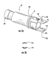
- Fig. 5 depicts an exploded view of preconnectorized cable 10 showing cable 40' as disclosed in U.S. Pat. No. 6,542,674 and plug connector 50.
- Cable 40' is similar to cable 40, but it does not include the toning lobe and both cables may use the same plug connector design.
- plug connector 50 includes an industry standard SC type connector assembly 52 having a connector body 52a, a ferrule 52b in a ferrule holder (not numbered), a spring 52c, and a spring push 52d.
- Plug connector 50 also includes a crimp assembly (not numbered) that includes a crimp housing having at least one half-shell 55a and a crimp band 54, a shroud 60 having an O-ring 59, a coupling nut 64, a cable boot 66, a heat shrink tube 67, and a protective cap 68 secured to boot 66 by a wire assembly 69.
- a crimp assembly (not numbered) that includes a crimp housing having at least one half-shell 55a and a crimp band 54, a shroud 60 having an O-ring 59, a coupling nut 64, a cable boot 66, a heat shrink tube 67, and a protective cap 68 secured to boot 66 by a wire assembly 69.
- plug connector 50 are formed from a suitable polymer.
- the polymer is a UV stabilized polymer such as ULTEM 2210 available from GE Plastics; however, other suitable materials are possible. For instance, stainless steel or any other suitable metal may be used for various components.
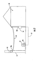
- Fig. 7 shows a cross-sectional view of preconnectorized cable 10 taken along line 7-7 of Fig. 4 .
- the crimp assembly includes crimp housing 55 and crimp band 54.
- Crimp housing 55 has two half-shells 55a that are held together by cr imp band 54 when the preconnectorized cable is assembled.
- the term half-shell is used, it is to be understood that it means suitable shells and includes shells that are greater than or less than half of the crimp housing.
- Crimp band 54 is preferably made from brass, but other suitable crimpable materials may be used.
- Crimp housing 55 is configured for securing connector assembly 52 as well as providing strain relief to cable 40'. This advantageously results in a relatively compact connector arrangement using fewer components. Moreover, the crimp assembly allows preconnectorized cable 10 to be assembled quickly and easily.
- connector body 52a may be integrally molded into crimp housing 55 in a ST type configuration so that a twisting motion of the crimp housing secures the ST-type connector with a comp lementary mating receptacle.
- Figs. 6a-6d depict several steps during the process of attaching the crimp assembly to cable 40'.
- Fig. 6a shows cable 40' having strength members 45 (not visible) cut flush with the stripped back jacket 48, thereby exposing the two grp strength components 44 and optical component 42 from the end of cable 40'.
- Fig. 6b shows the inner surface of one half-shell 55a. In this case, only one half-shell 55a is illustrated since two symmetrical half-shells are used for both halves of crimp housing 55.
- one half-shell may have two alignment pins, rather than each half-shell having a single alignment pin.
- half-shell 55a includes a first end 55b for securing connector assembly 52 and a second end 55c that provides strain relief.
- a longitudinal axis A-A is formed between first end 55b and second end 55c near the center of crimp housing 55, through which half of a longitudinal passage is formed.
- optical fiber 46 passes through the longitudinal passage and is held in a bore of ferrule 52b.
- half-shell 55a includes a cable clamping portion 56 and a connector assembly clamping portion 57.
- Cable clamping portion 56 has two outboard half-pipe passageways 56a and a central half-pipe passageway 56b that is generally disposed along longitudinal axis A-A.
- Half-pipe passageways 56a and 56b preferably include at least one rib 56c for securely clamping optical component 42 and strength components 44 after crimp band 54 is crimped, thereby completing the crimp assembly.
- half-pipe passageways 56a and 56b are sized for the components of cable 40', but the passageways can be sized for different cable configurations.
- half-shell 55a has a connector assembly clamping portion 57 that is sized for attaching connector assembly 52.
- connector assembly clamping portion 57 has a half-pipe passageway 57a that opens into and connects central half-pipe passageway 56b and a partially rectangular passageway 57b.
- Half-pipe passageway 57a is sized for securing spring push 52d and may include one or more ribs for that purpose.
- Rectangular passageway 57b holds a portion of connector body 52a therein and inhibits the rotation between connector assembly 52 and the crimp assembly.
- Fig. 6c depicts prepared cable 40' of Fig. 6a having connector assembly 52 attached and positioned in a first half-shell 55a.
- Fig. 6d shows both half-shells 55a of crimp housing 55 disposed about cable 40' before crimp band 54 is installed thereover. Additionally, half-shells may include one or more bores 56d that lead to one of half-pipe passageways 56a or 56b. Bores 56d allow for inserting an adhesive or epoxy into the crimp housing 55, thereby providing a secure connection for strain relief.
- crimp housing 55 is keyed to direct the insertion of the crimp assembly into shroud 60.
- half-shells 55a include planar surfaces 57e ( Fig. 6d ) on opposites sides of crimp housing 55 to inhibit relative rotation between crimp housing 55 and shroud 60.
- the crimp assembly may be keyed to the shroud using other configurations such as a complementary protrusion/groove or the like.
- Shroud 60 has a generally cylindrical shape with a first end 60a and a second end 60b. Shroud generally protects connector assembly 52 and in preferred embodiments also keys plug connector 50 with the respective mating receptacle 30. Moreover, shroud 60 includes a through passageway between first and second ends 60a and 60b. As discussed, the passageway of shroud 60 is keyed so that crimp housing 54 is inhibited from rotating when plug connector 50 is assembled. Additionally, the passageway has an internal shoulder (not numbered) that inhibits the crimp assembly from being inserted beyond a predetermined position.
- first end 60a of shroud 60 includes at least one opening (not numbered) defined by shroud 60.
- the at least one opening extends from a medial portion of shroud 60 to first end 60a.
- shroud 60 includes a pair of openings on opposite sides of first end 60a, thereby defining alignment portions or fingers 61a,61b.
- alignment fingers 61a,61b may extend slightly beyond connector assembly 52, thereby protecting the same.
- alignment fingers 61a,61b have different shapes so plug connector 50 and receptacle 30 only mate in one orientation.
- this orientation is marked on shroud 60 using alignment indicia 60c so that the craftsman can quickly and easily mate preconnectorized cable 10 with receptacle 30.
- alignment indicia 60c is an arrow molded into the top alignment finger of shroud 60, however, other suitable indicia may be used.
- the arrow is aligned with complimentary alignment indicia 30c disposed on receptacle 30, thereby allowing the craftsman to align indicia 60c,30c so that alignment fingers 61a,61b can be seated into receptacle 30.
- the craftsman engages the external threads of coupling nut 64 with the complimentary internal threads of receptacle 30 to make the optical connection as shown in Fig. 3c .
- a medial portion of shroud 60 has a groove 62 for seating an O-ring 59.
- O-ring 59 provides a weatherproof seal between plug connector 50 and receptacle 30 or protective cap 68.
- the medial portion also includes a shoulder 60d that provides a stop for coupling nut 64.
- Coupling nut 64 has a passageway sized so that it fits over the second end 60b of shroud 60 and easily rotates about the medial portion of shroud 60. In other words, coupling nut 64 cannot move beyond shoulder 60d, but coupling nut 64 is able to rotate with respect to shroud 60.
- Second end 60b of shroud 60 includes a stepped down portion having a relatively wide groove (not numbered).
- This stepped down portion and groove are used for securing heat shrink tubing 67.
- Heat shrink tubing 67 is used for weatherproofing the preconnectorized cable. Specifically, the stepped down portion and groove allow for the attachment of heat shrink tubing 67 to the second end 60b of shroud 60. The other end of heat shrink tubing 67 is attached to cable jacket 48, thereby inhibiting water from entering plug connector 50.
- boot 66 is slid over heat shrink tubing 67 and a portion of shroud 60.
- Boot 66 is preferably formed from a flexible material such as KRAYTON. Heat shrink tubing 67 and boot 66 generally inhibit kinking and provide bending strain relief to the cable near plug connector 50.
- Boot 66 has a longitudinal passageway (not visible) with a stepped profile therethrough. The first end of the boot passageway is sized to fit over the second end of shroud 60 and heat shrink tubing 67. The first end of the boot passageway has a stepped down portion sized for cable 40' and the heat shrink tubing 67 and acts as stop for indicating that the boot is fully seated.
- coupling nut 64 is slid up to shoulder 60c so that wire assembly 69 can be secured to boot 66. Specifically, a first end of wire assembly 69 is positioned about groove 66a on boot 66 and wire 69a is secured thereto using a first wire crimp (not numbered). Thus, coupling nut 64 is captured between shoulder 60c of shroud 60 and wire assembly 69 on boot 66. This advantageously keeps coupling nut 64 in place by preventing it from sliding past wire assembly 69 down onto cable 40'.
- wire assembly 69 is secured to protective cap 68 using a second wire crimp (not numbered). Consequently, protective cap 68 is prevented from being lost or separated from preconnectorized cable 10.
- wire assembly 69 is attached to protective cap 68 at an eyelet 68a. Eyelet 68a is also useful for attaching a fish-tape so that preconnectorized cable 10 can be pulled through a duct.
- Protective cap 68 has internal threads for engaging the external threads of coupling nut 64.
- O-ring 59 provides a weatherproof seal between plug connector 50 and protective cap 68 when installed. When threadly engaged, protective cap 68 and coupling nut 64 may rotate with respect to the remainder of preconectorized cable 10, thus inhibiting torsional forces during pulling.
- Preconnectorized cable 10 may have any suitable length desired, however, preconnectorized cable 10 can have standardized lengths.
- preconnectorized cable 10 may include a length marking indicia for identifying its length.
- the length marking indicia may be a marking located on the cable such as a colored stripe or denoted in a print statement.
- the length marking indicia may be a marking located on plug connector 50.
- length marking indicia may be denoted by a marking on coupling nut 64 or protective cap 68 such as a colored stripe.
- the length marking indicia should be easily visible so the craftsperson may identify the preconnectorized cable length. For instance, a red marking indicia on coupling nut 64 denotes a length of about 50 feet while an orange marking indicia denotes a length of about 100 feet.
- the described explanatory embodiment provides an optical connection that can be made in the field without any special tools, equipment, or training. Additionally, the optical connection is easily connected or disconnected by merely mating or unmating the ends of preconnectorized cable 10 with the respective receptacle by threadly engaging or disengageing coupling nut 64.
- the preconnectorized cables of the present invention allow deployment of optical waveguides to the location 'x' in an easy and economical manner, thereby providing the end user with increased bandwidth.
- the concepts of the present invention can be practiced with other fiber optic cables, connectors and/or other preconnectorized cable configurations.
- Fig. 8 is a cross-sectional view of another fiber optic cable 80 suitable with the concepts of the present invention.
- Cable 80 is an explanatory figure eight cable design having a messenger section 82 and a carrier section 84 connected by a web 83.
- Messenger section 82 includes at least one strength component 86 having anti-buckling strength and tensile strength for carrying a load.
- Strength component 86 can be formed from any suitable material such as dielectrics or conductors, moreover, a plurality of strength components 86 may be stranded together as shown.
- carrier section 84 includes an optical component that includes at least one optical waveguide 81 and a buffer tube 85, and generally excludes strength components and strength members.
- preconnectorized cables of the present invention may use figure eight cables having strength components and/or strength members in the carrier section.
- the messenger and carrier sections 82,84 include a common cable jacket 89.
- Common jacket 89 includes a messenger jacket 89a and a carrier jacket 89.
- carrier section 84 also includes at least one ripcord 87 for accessing optical waveguide 81.
- a preconnectorized cable employing cable 80 uses a design similar to preconnectorized cable 10, but some of the components are different due to the figure eight design of cable 80. Specifically, cable 80 requires a different crimp housing than used for cables 40 or 40'.
- Fig. 9 illustrates a half-shell 95a that is suitable for using as a portion of the crimp housing for preconnectorizing cable 80.
- half-shell 95a has the same outer dimensions as half-shell 55a so by merely substituting crimp housings different cable designs may be used with plug connector 50.
- crimp housing 95 uses two symmetrical half-shells 95a, thus only one half-shell requires illustration.
- passageway 96b is not symmetric about longitudinal axis A-A. Instead, passageway 96a has a non-symmetrical curvilinear path between first end 95b and second end 95c about longitudinal axis A-A. Furthermore, embodiments of the present invention may use crimp housings having other configurations for different cables.
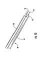
- Fig. 10 illustrates fiber optic cable 80 having an end prepared for connectorization. Specifically, a portion of jacket 89 is stripped back, thereby exposing strength component 86, buffer tube 85, and optical waveguide 81- Next, connector assembly 52 is attached to optical waveguide 81 forming a subassembly. Thereafter, the subassembly is placed into the proper portions of half-shell 95a. Like half-shell 55, half-shell 95a includes a cable clamping portion 96 and a connector assembly clamping portion 97. Crimp housing 95 (not shown) is then formed about a portion of the subassembly by placing a second half-shell 95a onto the first half-shell 95a.
- half-shell 95a includes a first end 95b for securing connector assembly 52 and a second end 95c that provides strain relief.
- a longitudinal axis A-A is formed between first end 95b and second end 95c near the center of the crimp housing.
- a through longitudinal passage is formed between first ends 95b and second ends 95c of crimp housing 95; however, the passageway is not generally symmetrical about longitudinal axis A-A.
- optical fiber 81 passes through the longitudinal passage and is held in a bore of ferrule 52b.
- Cable clamping portion 96 has a single half-pipe passageway 96a and a curvilinear half-pipe passageway 96b.
- Half-pipe passageways 96a and 96b preferably include a plurality of ribs 96c for securely clamping buffer tube 85 and strength component 86 after crimp band 54 is crimped about crimp housing 95, thereby completing the crimp assembly.
- half-shell 95a has a connector assembly clamping portion 97 that is sized for attaching connector assembly 52.
- connector assembly clamping portion 97 has a half-pipe passageway 97a that opens into and connects curvilinear half-pipe passageway 96b and a partially rectangular passageway 97b.
- Half-pipe passageway 97a is sized for securing spring push 52d and may include one or more ribs for that purpose.
- Rectangular passageway 97b holds a portion of connector body 52a therein and inhibits the rotation between connector assembly 52 and the crimp assembly.
- the alignment of the two half shells 95a is accomplished by inserting pins 97c into complementary bores 97d of the two half-shells.
- half-shells 95a may include one or more bores 96d that lead to one of half-pipe passageways for inserting an adhesive or epoxy into the crimp housing.
- Preconnectorized cables of the present invention can also terminate more than one optical waveguide.
- a plurality of optical waveguide can be arranged loosely, disposed in a ribbon, or bundlized.
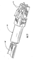
- Fig. 11 depicts a cable 40'' having more than one optical waveguide therein.
- a crimp housing 114 is suitable for securing more than one connector assembly 112.
- half-shell 114a has two connector assembly clamping portions 117.
- the half-shells of crimp housing 114 are non-symmetrical since half-shell 114a has a bore 117a and the complementary half-shell (not shown) would have an alignment pin.
- crimp housings of the present invention may hold one or more multi-fiber ferrules.
- Figs. 13a-13n depict suitable cables 130a-130n having at least one strength component or strength member 134, at least one optical waveguide 136, and a cable jacket 138. Cables 130a-130n will be briefly described. Additionally, all of the disclosures of the below mentioned patents and patent applications are incorporated herein by reference.
- Fig. 13a shows a cable 130a that is similar to cable 40 that has a toning portion 131a.
- cable 130a does not include strength members 45 that lack anti-buckling strength.
- optical waveguide 136 is a portion of an optical fiber ribbon, but other suitable configurations such as tight-buffered optical fiber may be used.
- Fig. 13b is another similar cable design having a toning portion 131b, but jacket 138 has a medial lobe surrounding a tube that houses optical waveguides 136, which are disposed in a bundle.
- Suitable cable designs may also include a toning portion that can be configured as a separate lobe connected by a web or integrated into a cable body.
- Fig. 13c shows a round cable 130c as disclosed in U.S. Pat. App. Ser. No. 09/822,528 and Ser. No. 09/822,529 both filed on March 30, 2001 .
- optical waveguide 136 has a buffer layer (not numbered) for protection.
- Fig. 13d depicts a variation of the strength component 134 of cable 130c for a flat drop cable.
- Fig. 13e is a round cable 130e having a plurality of strength members 134 such as aramid fibers or fiberglass rovings.
- strength members 134 of cable 130e are secured to plug connector 50 by being captured between an outer barrel 55o of crimp housing 55 and the inner diameter of crimp band 54 during crimping.
- Fig. 14a shows a cable 130e prepared for connectorization
- Fig. 14b shows strength members 134 being positioned about outer barrel 550 before installing crimp band 54.
- Cable 130f is a variation of cable 130e having a generally flat shape. Thus, part of the passageway through the boot of the plug connector 50 should conform with the cable profile, thereby allowing the boot to be slid onto the cable.
- Fig. 13g depicts yet another cable 130g as disclosed in U.S. Pat. No. 6,256,438 .
- strength component 134 is an armor tube that houses optical waveguides 136 and water-swellable element 137 such as a water-swellable yarn.
- Fig. 13h shows another figure-eight cable as disclosed in U.S. Pat. No. 6,356,690 .
- Cable 130h includes strength components 134 in both the messenger and carrier sections. The primary strength is provided by the strength component of the messenger section, but the strength components of the carrier section generally inhibit shrinkback of carrier jacket 138b when the two sections are separated. Moreover, strength components 134 in the carrier section are generally located along plane A-A. Fig.
- 13i shows cable 130i, which is another variation of a figure-eight cable.
- a slotted core 135 is used for holding optical ribbons in a plurality of stacks, but other configurations are possible.
- Slotted core 135 is wrapped with a water-swellable element 137 such as a tape, which is secured with one or more binder threads before jacket is extruded thereover.
- Fig. 13j shows cable 130j as disclosed in U.S. Pat. No. 6,621,964 .
- Cable 130j includes two non-stranded strength components 134 with optical waveguides 136 and water-swellable components 137 surrounded by jacket 138.
- Fig. 13k illustrates cable 130k as also disclosed in U.S. Pat. No. 6,621,964 .
- Cable 130k has inner and outer components that may be strength components 134 that house at least one optical waveguide 136 generally surrounded by a jacket 138.
- Fig. 13l shows cable 1301 as disclosed in U.S. Pat. No. 6,618,526 .
- Cable 1301 has two strength components 134 that share two or more interfaces with a retention area therebetween that houses optical waveguide 136.
- Figs. 13m and 13n show cables 130m and 130n having a dry insert 131 as disclosed in U.S. Pat. App. Ser. Nos. 10/326,022 filed on Dec. 19, 2002 and 10/661,204 filed on Sept. 12, 2003 . Additionally, cables 13m and 13n are tubeless cable designs. In other words, the craftsman does not have to open a buffer tube to access the optical waveguides. Cable 130m includes optical waveguides 136 generally disposed within dry insert 131, and one or more binder threads that secure dry insert 131, two strength components 134, and jacket 138. Cable 130m also has a pair of ripcords 133 disposed about 180 degrees apart.
- Cable jacket 138 includes a plurality of ears 139 that are generally disposed to indicate the location of ripcords 133 to the craftsman.
- Fig. 13n shows a figure-eight cable 130n that is similar to cable 130m, except it includes a messenger section connected by a web.
- other cable design may use a dry insert and/or have a tubeless configuration.
- the illustrated cables may also include other components, configurations, and/or different materials.
- cables can include components such as armor layers, ripcords, water-swellable yarns, tapes, or powders.
- Optical waveguide can also be loose, ribbonized, or have buffer layers.
- the preconnectorized cables according to the present invention may also have electrical power components that are connected and disconnected through the plug connector.
- Figs. 15a and 15b depict cables 150a and 150b that are suitable for carrying electrical power.
- Cable 150a has insulated electrical wires 151 located in outboard lobes of jacket 138.
- Cable 150b also includes electrical wires 151 on the outboard portions surrounded by jacket 138 having preferential tear portions 138c.
- Electrical wires 151 are also multi-functional since they act as strength components in these cable designs.
- Electrical wires 151 may be any suitable electrical conductor such as copper wires or copper clad steel.
- electrical wires 151 would be electrically connected with respective conductive terminals of the plug connector that are suitable for mating with complementary electrical terminals in the receptacle.
- electrical wires 151 may be in electrical communication with a portion of a conductive terminal.
- the electrical terminal may run from electrical wire 151 in the half shell to the connector assembly 52 or adjacent to fingers 61a,61b; however, other suitable configurations are possible.
Landscapes
- Physics & Mathematics (AREA)
- General Physics & Mathematics (AREA)
- Optics & Photonics (AREA)
- Mechanical Coupling Of Light Guides (AREA)
- Light Guides In General And Applications Therefor (AREA)
Applications Claiming Priority (3)
| Application Number | Priority Date | Filing Date | Title |
|---|---|---|---|
| US10/963,045 US7113679B2 (en) | 2000-05-26 | 2004-10-12 | Fiber optic drop cables and preconnectorized assemblies having toning portions |
| EP08003955A EP1959282A3 (de) | 2004-10-12 | 2005-03-30 | Freiluft-Glasfaserkabel und vorconnectorisierte Baugruppen mit Toning-Teilen |
| EP05732402A EP1800155A1 (de) | 2004-10-12 | 2005-03-30 | Faseroptische auskoppelkabel und vorconnectorisierte baugruppen mit toning-teilen |
Related Parent Applications (1)
| Application Number | Title | Priority Date | Filing Date |
|---|---|---|---|
| EP08003955A Division EP1959282A3 (de) | 2004-10-12 | 2005-03-30 | Freiluft-Glasfaserkabel und vorconnectorisierte Baugruppen mit Toning-Teilen |
Publications (1)
| Publication Number | Publication Date |
|---|---|
| EP2090912A1 true EP2090912A1 (de) | 2009-08-19 |
Family
ID=34964429
Family Applications (3)
| Application Number | Title | Priority Date | Filing Date |
|---|---|---|---|
| EP09003586A Withdrawn EP2090912A1 (de) | 2004-10-12 | 2005-03-30 | Faseroptische Auskoppelkabel und vorverbundene Baugruppen mit Toning-Teilen |
| EP05732402A Withdrawn EP1800155A1 (de) | 2004-10-12 | 2005-03-30 | Faseroptische auskoppelkabel und vorconnectorisierte baugruppen mit toning-teilen |
| EP08003955A Withdrawn EP1959282A3 (de) | 2004-10-12 | 2005-03-30 | Freiluft-Glasfaserkabel und vorconnectorisierte Baugruppen mit Toning-Teilen |
Family Applications After (2)
| Application Number | Title | Priority Date | Filing Date |
|---|---|---|---|
| EP05732402A Withdrawn EP1800155A1 (de) | 2004-10-12 | 2005-03-30 | Faseroptische auskoppelkabel und vorconnectorisierte baugruppen mit toning-teilen |
| EP08003955A Withdrawn EP1959282A3 (de) | 2004-10-12 | 2005-03-30 | Freiluft-Glasfaserkabel und vorconnectorisierte Baugruppen mit Toning-Teilen |
Country Status (8)
| Country | Link |
|---|---|
| US (4) | US7113679B2 (de) |
| EP (3) | EP2090912A1 (de) |
| CN (3) | CN100538419C (de) |
| AU (5) | AU2005296272B2 (de) |
| CA (5) | CA2996111C (de) |
| HU (3) | HU4293U (de) |
| MX (1) | MX2007004435A (de) |
| WO (1) | WO2006043967A1 (de) |
Families Citing this family (282)
| Publication number | Priority date | Publication date | Assignee | Title |
|---|---|---|---|---|
| US9239441B2 (en) | 2000-05-26 | 2016-01-19 | Corning Cable Systems Llc | Fiber optic drop cables and preconnectorized assemblies having toning portions |
| US7113679B2 (en) * | 2000-05-26 | 2006-09-26 | Corning Cable Systems, Llc | Fiber optic drop cables and preconnectorized assemblies having toning portions |
| US7467896B2 (en) * | 2000-05-26 | 2008-12-23 | Corning Cable Systems Llc | Fiber optic drop cables and preconnectorized assemblies |
| US6970629B2 (en) | 2002-12-19 | 2005-11-29 | Corning Cable Systems Llc | Optical tube assembly having a dry insert and methods of making the same |
| US7415181B2 (en) | 2005-07-29 | 2008-08-19 | Corning Cable Systems Llc | Fiber optic cables and assemblies for fiber to the subscriber applications |
| US7471862B2 (en) | 2002-12-19 | 2008-12-30 | Corning Cable Systems, Llc | Dry fiber optic cables and assemblies |
| US7336873B2 (en) | 2002-12-19 | 2008-02-26 | Corning Cable Systems, Llc. | Optical tube assembly having a dry insert and methods of making the same |
| US6962445B2 (en) | 2003-09-08 | 2005-11-08 | Adc Telecommunications, Inc. | Ruggedized fiber optic connection |
| US7674046B2 (en) * | 2003-09-22 | 2010-03-09 | Belden Cdt (Canada) Inc. | Fibre optic connector keying system |
| US7120347B2 (en) * | 2004-01-27 | 2006-10-10 | Corning Cable Systems Llc | Multi-port optical connection terminal |
| US8434115B1 (en) * | 2004-06-03 | 2013-04-30 | Verizon Services Corp. | Multi-component ONT power supply |
| US7313304B2 (en) * | 2004-08-09 | 2007-12-25 | Sumitomo Electric Lightwave Corp. | Locatable dielectric optical fiber cable having easily removable locating element |
| US7680388B2 (en) | 2004-11-03 | 2010-03-16 | Adc Telecommunications, Inc. | Methods for configuring and testing fiber drop terminals |
| US7489849B2 (en) * | 2004-11-03 | 2009-02-10 | Adc Telecommunications, Inc. | Fiber drop terminal |
| US20060153516A1 (en) * | 2005-01-13 | 2006-07-13 | Napiorkowski John J | Network interface device having integral slack storage compartment |
| KR20080003433A (ko) | 2005-04-19 | 2008-01-07 | 에이디씨 텔레커뮤니케이션스 인코포레이티드 | 루프 백 플러그 및 방법 |
| DE202005008136U1 (de) * | 2005-05-24 | 2005-07-21 | CCS Technology, Inc., Wilmington | Konfektioniertes Lichtwellenleiterkabel |
| US7454107B2 (en) | 2005-11-01 | 2008-11-18 | Corning Cable Systems Llc | Fiber optic cables suitable for automated preconnectorization |
| US7590321B2 (en) * | 2006-03-09 | 2009-09-15 | Adc Telecommunications, Inc. | Mid-span breakout with helical fiber routing |
| US7317863B2 (en) * | 2006-03-09 | 2008-01-08 | Adc Telecommunications, Inc. | Fiber optic cable breakout configuration with retention block |
| US7424189B2 (en) * | 2006-03-09 | 2008-09-09 | Adc Telecommunications, Inc. | Mid-span breakout with potted closure |
| US7665902B2 (en) | 2006-05-11 | 2010-02-23 | Draka Comteq, B.V. | Modified pre-ferrulized communication cable assembly and installation method |
| NL1031792C2 (nl) * | 2006-05-11 | 2007-11-13 | Draka Comteq Bv | Kabelsamenstel alsmede werkwijze voor het installeren van een dergelijk kabelsamenstel. |
| US7599598B2 (en) | 2006-08-09 | 2009-10-06 | Adc Telecommunications, Inc. | Cable payout systems and methods |
| US20080037946A1 (en) * | 2006-08-14 | 2008-02-14 | John George | Multicable clamp |
| WO2008021253A2 (en) * | 2006-08-14 | 2008-02-21 | Adc Telecommunications, Inc. | Factory spliced cable assembly |
| US7840109B2 (en) * | 2006-08-14 | 2010-11-23 | Adc Telecommunications, Inc. | Factory spliced cable assembly |
| US7568844B2 (en) * | 2006-08-15 | 2009-08-04 | Corning Cable Systems Llc | Ruggedized fiber optic connector assembly |
| EP2057083B1 (de) * | 2006-08-31 | 2012-05-30 | Huhtamaki Ronsberg, Zweigniederlassung der Huhtamaki Deutschland GmbH & Co. KG | Verpackungsbehälter, insbesondere dosenartiger behälter |
| EP2074455B1 (de) | 2006-09-05 | 2012-04-04 | Prysmian Cables & Systems Limited | System zum einstecken eines faseroptischen kabels in eine faseroptische buchse und kabeladapter dafür |
| US7480436B2 (en) * | 2006-10-10 | 2009-01-20 | Adc Telecommunications, Inc. | Systems and methods for securing a tether to a distribution cable |
| US7403685B2 (en) * | 2006-10-13 | 2008-07-22 | Adc Telecommunications, Inc. | Overmold zip strip |
| US7934874B2 (en) * | 2006-11-13 | 2011-05-03 | Sumitomo Electric Industries, Ltd. | Holder, fusion-splicing apparatus, and manufacturing method of optical connector |
| US7526163B2 (en) * | 2006-11-30 | 2009-04-28 | Corning Cable Systems Llc | Locatable cables and cable components therefor |
| US7901240B2 (en) * | 2007-01-12 | 2011-03-08 | Power Feed-Thru Systems & Connectors, Llc | Apparatus and method for electrical connector with flat cable adapter |
| US7572065B2 (en) | 2007-01-24 | 2009-08-11 | Adc Telecommunications, Inc. | Hardened fiber optic connector |
| US7591595B2 (en) * | 2007-01-24 | 2009-09-22 | Adc Telelcommunications, Inc. | Hardened fiber optic adapter |
| US7614797B2 (en) | 2007-01-24 | 2009-11-10 | Adc Telecommunications, Inc. | Fiber optic connector mechanical interface converter |
| US7489843B2 (en) * | 2007-02-06 | 2009-02-10 | Adc Telecommunications, Inc. | Polyurethane to polyethylene adhesion process |
| US7558458B2 (en) * | 2007-03-08 | 2009-07-07 | Adc Telecommunications, Inc. | Universal bracket for mounting a drop terminal |
| US7556437B2 (en) * | 2007-03-13 | 2009-07-07 | Adc Telecommunications, Inc. | Fiber optic connector with protective cap |
| US7738759B2 (en) * | 2007-03-16 | 2010-06-15 | 3M Innovative Properties Company | Optical fiber cable inlet device |
| US7532799B2 (en) * | 2007-04-12 | 2009-05-12 | Adc Telecommunications | Fiber optic telecommunications cable assembly |
| US7609925B2 (en) * | 2007-04-12 | 2009-10-27 | Adc Telecommunications, Inc. | Fiber optic cable breakout configuration with tensile reinforcement |
| US7534050B2 (en) * | 2007-04-13 | 2009-05-19 | Adc Telecommunications, Inc. | Field terminatable fiber optic connector assembly |
| US7722258B2 (en) | 2007-05-06 | 2010-05-25 | Adc Telecommunications, Inc. | Interface converter for SC fiber optic connectors |
| US7677814B2 (en) | 2007-05-06 | 2010-03-16 | Adc Telecommunications, Inc. | Mechanical interface converter for making non-ruggedized fiber optic connectors compatible with a ruggedized fiber optic adapter |
| US7686519B2 (en) | 2007-06-18 | 2010-03-30 | Adc Telecommunications, Inc. | Hardened fiber optic housing and cable assembly |
| US7769261B2 (en) * | 2007-09-05 | 2010-08-03 | Adc Telecommunications, Inc. | Fiber optic distribution cable |
| US7740409B2 (en) * | 2007-09-19 | 2010-06-22 | Corning Cable Systems Llc | Multi-port optical connection terminal |
| US7567741B2 (en) * | 2007-11-26 | 2009-07-28 | Corning Cable Systems Llc | Fiber optic cables and assemblies for fiber toward the subscriber applications |
| US7539380B1 (en) | 2007-11-26 | 2009-05-26 | Corning Cable Systems Llc | Fiber optic cables and assemblies for fiber toward the subscriber applications |
| US7942590B2 (en) | 2007-12-11 | 2011-05-17 | Adc Telecommunications, Inc. | Hardened fiber optic connector and cable assembly with multiple configurations |
| US20090220197A1 (en) * | 2008-02-22 | 2009-09-03 | Jeffrey Gniadek | Apparatus and fiber optic cable retention system including same |
| US20090214162A1 (en) * | 2008-02-22 | 2009-08-27 | Senko Advanced Components, Inc. | Apparatus and fiber optic cable retention system including same |
| US7708469B2 (en) * | 2008-04-11 | 2010-05-04 | Corning Cable Systems Llc | Fiber optic connector assembly and method for venting gas inside a fiber optic connector sub-assembly |
| EP2283390B1 (de) * | 2008-04-21 | 2016-11-09 | ADC Telecommunications, INC. | Gehärteter faseroptischer verbinder mit einem verbinderkörper, der durch ein unitäres gehäuse mit einem zylindrischen kabel verbunden wird |
| US7787740B2 (en) * | 2008-06-12 | 2010-08-31 | Corning Cable Systems Llc | Universal cable bracket |
| US8452148B2 (en) | 2008-08-29 | 2013-05-28 | Corning Cable Systems Llc | Independently translatable modules and fiber optic equipment trays in fiber optic equipment |
| US11294136B2 (en) | 2008-08-29 | 2022-04-05 | Corning Optical Communications LLC | High density and bandwidth fiber optic apparatuses and related equipment and methods |
| US20100322583A1 (en) | 2009-06-19 | 2010-12-23 | Cooke Terry L | High Density and Bandwidth Fiber Optic Apparatuses and Related Equipment and Methods |
| EP2338076B1 (de) | 2008-09-23 | 2013-07-31 | Corning Cable Systems LLC | Faseroptisches Kabel |
| US8303193B2 (en) * | 2008-09-30 | 2012-11-06 | Corning Cable Systems Llc | Retention bodies for fiber optic cable assemblies |
| US8272792B2 (en) * | 2008-09-30 | 2012-09-25 | Corning Cable Systems Llc | Retention bodies for fiber optic cable assemblies |
| US8285096B2 (en) | 2008-09-30 | 2012-10-09 | Corning Cable Systems Llc | Fiber optic cable assemblies and securing methods |
| US7621675B1 (en) | 2009-02-13 | 2009-11-24 | Ofs Fitel, Llc | Single-piece cable retention housing for hardened outside plant connector |
| US8582941B2 (en) * | 2009-02-16 | 2013-11-12 | Corning Cable Systems Llc | Micromodule cables and breakout cables therefor |
| ATE534049T1 (de) | 2009-02-24 | 2011-12-15 | Ccs Technology Inc | Haltevorrichtung für ein kabel oder eine anordnung zur verwendung mit einem kabel |
| EP3399672B1 (de) | 2009-03-05 | 2022-07-27 | CommScope Technologies LLC | Verfahren, systeme und vorrichtung zur integration von drahtloser technologie in ein glasfasernetz |
| US8699838B2 (en) | 2009-05-14 | 2014-04-15 | Ccs Technology, Inc. | Fiber optic furcation module |
| US9075216B2 (en) | 2009-05-21 | 2015-07-07 | Corning Cable Systems Llc | Fiber optic housings configured to accommodate fiber optic modules/cassettes and fiber optic panels, and related components and methods |
| US8280216B2 (en) | 2009-05-21 | 2012-10-02 | Corning Cable Systems Llc | Fiber optic equipment supporting moveable fiber optic equipment tray(s) and module(s), and related equipment and methods |
| US8201322B2 (en) * | 2009-05-29 | 2012-06-19 | Schratz Gary F | Fiber optic connector tooling device |
| US8408815B2 (en) * | 2009-06-18 | 2013-04-02 | Senko Advanced Components, Inc. | Optical fiber connector and adapter |
| EP2443498B1 (de) | 2009-06-19 | 2020-06-24 | Corning Optical Communications LLC | Vorrichtung mit hoher glasfaserkabelbündelungsdichte |
| US8712206B2 (en) | 2009-06-19 | 2014-04-29 | Corning Cable Systems Llc | High-density fiber optic modules and module housings and related equipment |
| EP2302431B1 (de) | 2009-09-28 | 2019-03-27 | TE Connectivity Nederland B.V. | Dichtungsgehäuse für einen Verbinder an einem Kabel wie z. B. standardisierten Glasfaserverbinder |
| US20110073818A1 (en) * | 2009-09-29 | 2011-03-31 | Avago Technologies Fiber Ip (Singapore) Pte. Ltd. | Pulling torpedo having a mating feature thereon that mates with a mating feature formed on a cable boot |
| CN101707081A (zh) * | 2009-11-09 | 2010-05-12 | 王春鸿 | 带输电体的光缆 |
| US8500341B2 (en) * | 2009-11-20 | 2013-08-06 | Adc Telecommunications, Inc. | Fiber optic cable assembly |
| US10573433B2 (en) | 2009-12-09 | 2020-02-25 | Holland Electronics, Llc | Guarded coaxial cable assembly |
| US8625950B2 (en) | 2009-12-18 | 2014-01-07 | Corning Cable Systems Llc | Rotary locking apparatus for fiber optic equipment trays and related methods |
| US8449317B1 (en) | 2009-12-18 | 2013-05-28 | Carlisle Interconnect Technologies, Inc. | Sealed connector assembly and method of making |
| EP2355283A1 (de) | 2010-01-29 | 2011-08-10 | Tyco Electronics Raychem BVBA | Kabelabdichtungsvorrichtung, Kabelabschluss und Befestigungsvorrichtung |
| PT2355286T (pt) | 2010-01-29 | 2019-05-08 | Tyco Electronics Raychem Bvba | Dispositivo de impermeabilização e retenção de cabos |
| EP3584615A1 (de) | 2010-02-04 | 2019-12-25 | ADC Telecommunications, Inc. | Robustes glasfaser-/stromverbindungssystem |
| US8593828B2 (en) | 2010-02-04 | 2013-11-26 | Corning Cable Systems Llc | Communications equipment housings, assemblies, and related alignment features and methods |
| US8913866B2 (en) | 2010-03-26 | 2014-12-16 | Corning Cable Systems Llc | Movable adapter panel |
| US8837940B2 (en) | 2010-04-14 | 2014-09-16 | Adc Telecommunications, Inc. | Methods and systems for distributing fiber optic telecommunication services to local areas and for supporting distributed antenna systems |
| US9078287B2 (en) | 2010-04-14 | 2015-07-07 | Adc Telecommunications, Inc. | Fiber to the antenna |
| CA2796221C (en) | 2010-04-16 | 2018-02-13 | Ccs Technology, Inc. | Sealing and strain relief device for data cables |
| EP2381284B1 (de) | 2010-04-23 | 2014-12-31 | CCS Technology Inc. | Glasfaserverteilungsvorrichtung für Unterboden |
| US8705926B2 (en) | 2010-04-30 | 2014-04-22 | Corning Optical Communications LLC | Fiber optic housings having a removable top, and related components and methods |
| US9075217B2 (en) | 2010-04-30 | 2015-07-07 | Corning Cable Systems Llc | Apparatuses and related components and methods for expanding capacity of fiber optic housings |
| WO2011137236A1 (en) | 2010-04-30 | 2011-11-03 | Corning Cable Systems Llc | Fiber optic cables with access features and methods of making fiber optic cables |
| US9632270B2 (en) | 2010-04-30 | 2017-04-25 | Corning Optical Communications LLC | Fiber optic housings configured for tool-less assembly, and related components and methods |
| US8660397B2 (en) | 2010-04-30 | 2014-02-25 | Corning Cable Systems Llc | Multi-layer module |
| US8879881B2 (en) | 2010-04-30 | 2014-11-04 | Corning Cable Systems Llc | Rotatable routing guide and assembly |
| US9720195B2 (en) | 2010-04-30 | 2017-08-01 | Corning Optical Communications LLC | Apparatuses and related components and methods for attachment and release of fiber optic housings to and from an equipment rack |
| US9519118B2 (en) | 2010-04-30 | 2016-12-13 | Corning Optical Communications LLC | Removable fiber management sections for fiber optic housings, and related components and methods |
| US8870469B2 (en) | 2010-05-12 | 2014-10-28 | Adc Telecommunications, Inc. | Fiber optic connector and method of applying same to a fiber optic cable |
| WO2011143401A2 (en) | 2010-05-14 | 2011-11-17 | Adc Telecommunications, Inc. | Splice enclosure arrangement for fiber optic cables |
| US8718436B2 (en) | 2010-08-30 | 2014-05-06 | Corning Cable Systems Llc | Methods, apparatuses for providing secure fiber optic connections |
| WO2012036982A2 (en) | 2010-09-14 | 2012-03-22 | Adc Telecommunications, Inc. | A method of terminating a fiber optic cable |
| US9279951B2 (en) | 2010-10-27 | 2016-03-08 | Corning Cable Systems Llc | Fiber optic module for limited space applications having a partially sealed module sub-assembly |
| US8755663B2 (en) | 2010-10-28 | 2014-06-17 | Corning Cable Systems Llc | Impact resistant fiber optic enclosures and related methods |
| CN106886076B (zh) | 2010-10-28 | 2019-11-05 | 康宁光缆系统有限责任公司 | 具有挤出式接近特征的光纤电缆以及用于制造光纤电缆的方法 |
| US9116324B2 (en) | 2010-10-29 | 2015-08-25 | Corning Cable Systems Llc | Stacked fiber optic modules and fiber optic equipment configured to support stacked fiber optic modules |
| US8662760B2 (en) | 2010-10-29 | 2014-03-04 | Corning Cable Systems Llc | Fiber optic connector employing optical fiber guide member |
| EP2646867B1 (de) | 2010-11-30 | 2018-02-21 | Corning Optical Communications LLC | Halter für faservorrichtung und zugentlastungsvorrichtung |
| US8885998B2 (en) | 2010-12-09 | 2014-11-11 | Adc Telecommunications, Inc. | Splice enclosure arrangement for fiber optic cables |
| WO2012106513A1 (en) | 2011-02-02 | 2012-08-09 | Corning Cable Systems Llc | Dense shuttered fiber optic connectors and assemblies suitable for establishing optical connections for optical backplanes in equipment racks |
| DE102011011523B4 (de) | 2011-02-17 | 2013-05-29 | Tyco Electronics Services Gmbh | Faseroptische Verbindungsanordnung und Adapterhülse |
| EP2492730A1 (de) * | 2011-02-22 | 2012-08-29 | Tyco Electronics Raychem BVBA | Luftgeblasene Glasfaserbefestigung |
| US8636425B2 (en) | 2011-03-15 | 2014-01-28 | Adc Telecommunications, Inc. | Fiber optic connector |
| US9008485B2 (en) | 2011-05-09 | 2015-04-14 | Corning Cable Systems Llc | Attachment mechanisms employed to attach a rear housing section to a fiber optic housing, and related assemblies and methods |
| US9188747B2 (en) | 2011-05-23 | 2015-11-17 | Senko Advanced Components, Inc. | True one piece housing fiber optic adapter |
| WO2013003303A1 (en) | 2011-06-30 | 2013-01-03 | Corning Cable Systems Llc | Fiber optic equipment assemblies employing non-u-width-sized housings and related methods |
| US8540435B2 (en) | 2011-07-22 | 2013-09-24 | Corning Cable Systems Llc | Ferrule retainers having access window(s) for accessing and/or referencing a fiber optic ferrule, and related fiber optic connector assemblies, connectors, and referencing methods |
| RU2603237C2 (ru) | 2011-07-22 | 2016-11-27 | Адс Телекоммьюникейшнз, Инк. | Узел соединения волоконно-оптического кабеля с коннектором, имеющий средство фиксации волокна |
| EP2745155B1 (de) * | 2011-08-16 | 2019-11-20 | Corning Optical Communications LLC | Anschliessbare kabelanordnungen für innen- und aussenanwendungen |
| US8953924B2 (en) | 2011-09-02 | 2015-02-10 | Corning Cable Systems Llc | Removable strain relief brackets for securing fiber optic cables and/or optical fibers to fiber optic equipment, and related assemblies and methods |
| US9106981B2 (en) | 2011-10-03 | 2015-08-11 | Tyco Electronics Uk Ltd | Aggregation enclosure for elevated, outdoor locations |
| EP2748898B1 (de) | 2011-10-05 | 2017-07-05 | Senko Advanced Components, Inc. | Verriegelungsverbinder mit fernauslösung |
| CN103890627B (zh) * | 2011-10-05 | 2016-03-16 | 康宁光电通信有限责任公司 | 具有逆向光纤环路的光纤连接器总成 |
| FR2981462A1 (fr) * | 2011-10-12 | 2013-04-19 | Data Fibre | Cables fibres optiques pre-connectes et testes en usine et les accessoires associes pour le cablage fibre optique tres haut debit dans les logements collectifs et individuels |
| US9274302B2 (en) | 2011-10-13 | 2016-03-01 | Corning Cable Systems Llc | Fiber optic cables with extruded access features for access to a cable cavity |
| US9323022B2 (en) | 2012-10-08 | 2016-04-26 | Corning Cable Systems Llc | Methods of making and accessing cables having access features |
| US9069151B2 (en) | 2011-10-26 | 2015-06-30 | Corning Cable Systems Llc | Composite cable breakout assembly |
| CN102385118A (zh) * | 2011-10-27 | 2012-03-21 | 中航光电科技股份有限公司 | 光纤连接器及其适配器 |
| US9201208B2 (en) | 2011-10-27 | 2015-12-01 | Corning Cable Systems Llc | Cable having core, jacket and polymeric jacket access features located in the jacket |
| TWM429881U (en) * | 2011-11-14 | 2012-05-21 | Gloriole Electroptic Technology Corp | Fiber optic connector |
| US9038832B2 (en) | 2011-11-30 | 2015-05-26 | Corning Cable Systems Llc | Adapter panel support assembly |
| EP2812741A2 (de) | 2012-02-07 | 2014-12-17 | Tyco Electronics Raychem BVBA | Kabelendenzusammenfügung und entsprechendes verfahren für steckverbinder |
| WO2013122752A1 (en) | 2012-02-13 | 2013-08-22 | Corning Cable Systems Llc | Fiber optic cable sub -assemblies and methods of making said sub -assemblies |
| US8873926B2 (en) | 2012-04-26 | 2014-10-28 | Corning Cable Systems Llc | Fiber optic enclosures employing clamping assemblies for strain relief of cables, and related assemblies and methods |
| US9176285B2 (en) | 2012-05-03 | 2015-11-03 | Adc Telecommunications, Inc. | Fiber optic connector |
| CN104380163B (zh) | 2012-05-22 | 2016-09-14 | Adc电信公司 | 被加固的光纤连接器 |
| US8858090B2 (en) | 2012-06-05 | 2014-10-14 | Corning Cable Systems Llc | Ferrule holders with an integral lead-in tube employed in fiber optic connector assemblies, and related components, connectors, and methods |
| FR2991964B1 (fr) * | 2012-06-14 | 2014-12-12 | Decathlon Sa | Dispositif antivol a lien souple |
| RU2502098C1 (ru) * | 2012-06-22 | 2013-12-20 | Закрытое акционерное общество "Соединитель" | Волоконно-оптический соединитель байонетного типа |
| US9250409B2 (en) | 2012-07-02 | 2016-02-02 | Corning Cable Systems Llc | Fiber-optic-module trays and drawers for fiber-optic equipment |
| US8974124B2 (en) | 2012-08-16 | 2015-03-10 | Senko Advanced Components, Inc. | Fiber optic connector |
| US9696500B2 (en) | 2012-08-31 | 2017-07-04 | Corning Optical Communications LLC | Female hardened optical connectors for use with hybrid receptacle |
| EP2706635B1 (de) * | 2012-09-05 | 2017-03-08 | Tyco Electronics Nederland B.V. | Endkappe, Anordnung und Kit zum Abschließen eines Übertragungskabels |
| US9042702B2 (en) | 2012-09-18 | 2015-05-26 | Corning Cable Systems Llc | Platforms and systems for fiber optic cable attachment |
| ES2551077T3 (es) | 2012-10-26 | 2015-11-16 | Ccs Technology, Inc. | Unidad de gestión de fibra óptica y dispositivo de distribución de fibra óptica |
| WO2014085462A1 (en) | 2012-11-30 | 2014-06-05 | Tyco Electronics Corporation | Fiber optic connector with field installable outer connector housing |
| US9513444B2 (en) | 2013-02-26 | 2016-12-06 | Corning Optical Communications LLC | Female hardened optical connectors for use with male plug connectors |
| US8985862B2 (en) | 2013-02-28 | 2015-03-24 | Corning Cable Systems Llc | High-density multi-fiber adapter housings |
| US9482826B2 (en) * | 2013-03-15 | 2016-11-01 | Commscope Technologies Llc | Connector body for making crimp-less fiber optic cable connections |
| US9557505B2 (en) | 2013-03-18 | 2017-01-31 | Commscope Technologies Llc | Power and optical fiber interface |
| KR102234059B1 (ko) | 2013-03-18 | 2021-04-01 | 콤스코프 커넥티비티 엘엘씨 | 무선 네트워크를 위한 아키텍처 |
| EP2992371A2 (de) | 2013-05-02 | 2016-03-09 | Corning Optical Communications LLC | Verbinderanordnungen und verfahren zur bereitstellung von dichtungs- und spannungsentlastung |
| US9268103B2 (en) | 2013-05-10 | 2016-02-23 | Senko Advanced Components, Inc. | Interlockable fiber optic connector adaptors |
| WO2014185978A1 (en) | 2013-05-14 | 2014-11-20 | Adc Telecommunications, Inc. | Power/fiber hybrid cable |
| US9360649B2 (en) | 2013-05-22 | 2016-06-07 | Senko Advanced Components, Inc. | Cable guide for fiber optic cables |
| ES2700963T3 (es) | 2013-06-27 | 2019-02-20 | CommScope Connectivity Belgium BVBA | Dispositivo de anclaje para cable de fibra óptica para uso con conectores de fibra óptica y métodos de uso del mismo |
| ES2875964T3 (es) | 2013-07-15 | 2021-11-11 | Commscope Technologies Llc | Interfaz de fibra óptica y energía |
| MX2016000483A (es) | 2013-07-16 | 2016-04-07 | 3M Innovative Properties Co | Cubierta de telecomunicacion para conexion externa. |
| EP3022596A1 (de) | 2013-07-16 | 2016-05-25 | 3M Innovative Properties Company | Steckverbinder für die telekommunikationsgehäuse |
| DE202013006413U1 (de) | 2013-07-17 | 2014-10-22 | Leoni Bordnetz-Systeme Gmbh | Vorrichtung zur elektrischen Kontaktierung einer Abschirmung eines elektrischen Kabels an einem Gehäuse sowie vorkonfektioniertes elektrisches Kabel |
| ES2931529T3 (es) | 2013-08-26 | 2022-12-30 | Commscope Technologies Llc | Disposición de multiplexor de división de onda para redes de celdas pequeñas |
| US9140872B2 (en) * | 2013-09-17 | 2015-09-22 | Panduit Corp. | Hydra cable assembly and components thereof |
| US9618703B2 (en) | 2013-10-03 | 2017-04-11 | Senko Advanced Components, Inc. | Connector housing for securing an optical cable and methods of use and manufacture thereof |
| US9477049B2 (en) | 2013-12-20 | 2016-10-25 | Senko Advanced Components, Inc. | Lockable connectors and connection assemblies |
| US9535230B2 (en) | 2014-01-31 | 2017-01-03 | Senko Advanced Components, Inc. | Integrated fiber optic cable fan-out connector |
| CN104849815B (zh) | 2014-02-14 | 2017-01-18 | 泰科电子(上海)有限公司 | 光纤连接器及其组装方法 |
| CN104849816B (zh) | 2014-02-14 | 2017-01-11 | 泰科电子(上海)有限公司 | 光纤连接器及其组装方法 |
| ES2894250T3 (es) | 2014-04-14 | 2022-02-14 | Commscope Connectivity Belgica Bvba | Recinto de fibra óptica con cajón de gestión de cables |
| US9526818B2 (en) | 2014-04-15 | 2016-12-27 | Thoratec Corporation | Protective cap for driveline cable connector |
| US9297964B2 (en) | 2014-04-18 | 2016-03-29 | Senko Advanced Components, Inc. | Optical fiber connector assembly |
| WO2015175363A1 (en) | 2014-05-12 | 2015-11-19 | Corning Optical Communications LLC | Fiber optic cable assemblies for terminating a fiber optic cable and methods of making the same |
| US9274287B2 (en) | 2014-05-13 | 2016-03-01 | Senko Advanced Components, Inc. | Optical fiber connector and ferrule |
| US9618702B2 (en) | 2014-06-09 | 2017-04-11 | Senko Advanced Components, Inc. | Reduced-profile data transmission element connectors, adapters, and connection assemblies thereof |
| CN105445862B (zh) | 2014-07-09 | 2018-01-19 | 泰科电子(上海)有限公司 | 光纤连接器及其现场组装方法 |
| ES2784245T3 (es) | 2014-08-14 | 2020-09-23 | CommScope Connectivity Belgium BVBA | Conjunto de adaptador de fibra óptica |
| US9599778B2 (en) | 2014-10-22 | 2017-03-21 | Senko Advanced Components, Inc. | Latching connector with remote release |
| US9983366B2 (en) | 2014-11-04 | 2018-05-29 | 3M Innovative Properties Company | Field installed optical fiber connector for jacketed fiber cable and termination method |
| PL3215882T3 (pl) | 2014-11-04 | 2020-07-13 | CommScope Connectivity Belgium BVBA | Obudowa do stosowania w światłowodowej sieci rozdzielczej |
| BR112017011218A2 (pt) | 2014-11-26 | 2018-02-14 | Corning Optical Communications LLC | ?conectores de fibra óptica e submontagens com retenção dos elementos de resistência? |
| US9494745B2 (en) | 2015-01-16 | 2016-11-15 | Senko Advanced Components, Inc. | Sealable communication cable connection assemblies |
| AU2016222584B2 (en) | 2015-02-26 | 2020-08-13 | Commscope Technologies Llc | Distributed antenna architecture |
| US9658409B2 (en) | 2015-03-03 | 2017-05-23 | Senko Advanced Components, Inc. | Optical fiber connector with changeable polarity |
| CA2978049C (en) | 2015-03-06 | 2019-08-13 | Fujikura Ltd. | Plug-side optical connector and optical connector system |
| US9448369B1 (en) * | 2015-04-28 | 2016-09-20 | Senko Advanced Components, Inc. | Ingress protected optical fiber connector having small diameter (mini-IP connector) |
| US9482825B1 (en) * | 2015-04-28 | 2016-11-01 | Senko Advanced Components, Inc | Ingress protected optical fiber connector having small diameter (mini-IP connector) |
| BR112017024540A2 (pt) | 2015-05-15 | 2018-07-24 | Corning Optical Communications LLC | conjunto de cabo de fibra óptica para terminação de cabos de fibra óptica e métodos de fabricação |
| US9684139B2 (en) | 2015-05-29 | 2017-06-20 | Senko Advanced Components, Inc. | Optical fiber connector with changeable gender |
| CN106329227B (zh) * | 2015-06-19 | 2020-09-15 | 康普技术有限责任公司 | 用于射频连接器的防护帽及其使用方法 |
| EP3316013A4 (de) | 2015-06-23 | 2019-02-27 | ADC Telecommunications (Shanghai) Distribution Co., Ltd. | Glasfaserverbinderanordnung |
| US10228390B2 (en) * | 2015-08-11 | 2019-03-12 | Tektronix, Inc. | Cable assembly with spine for instrument probe |
| US10473868B2 (en) | 2015-11-30 | 2019-11-12 | Corning Optical Communications, Llc | Optical connector plug having a removable and replaceable mating interface |
| WO2017095928A1 (en) | 2015-11-30 | 2017-06-08 | Commscope Technologies Llc | Fiber optic connector and assembly thereof |
| WO2017106514A1 (en) | 2015-12-16 | 2017-06-22 | Commscope Technologies Llc | Field installed fiber optic connector |
| US10371901B2 (en) * | 2015-12-21 | 2019-08-06 | Multilink Inc. | Field installable connector system for drop cables and the like |
| EP3403123B1 (de) | 2016-01-12 | 2022-07-20 | Corning Optical Communications LLC | Gehärtete faseroptische verbinder mit einer mechanischen spleissverbinderanordnung |
| MX2018010817A (es) | 2016-03-10 | 2019-01-10 | Corning Optical Communications LLC | Conectores de fibra óptica a basé de férula con balanceo de retracción de la férula. |
| US10067299B2 (en) | 2016-06-29 | 2018-09-04 | Corning Optical Communications LLC | Tunable optical fiber connectors and connector and cable sub-assemblies and assemblies |
| WO2018017458A1 (en) | 2016-07-21 | 2018-01-25 | Corning Optical Communications LLC | Optical reflective filter devices and optical networks using the same |
| EP3318907B1 (de) * | 2016-11-07 | 2022-08-03 | Corning Optical Communications LLC | Vorkonfektionierte optische kabelanordnung mit gesichertem verstärkungselement |
| WO2018089623A1 (en) | 2016-11-09 | 2018-05-17 | Commscope, Inc. Of North Carolina | Exchangeable powered infrastructure module |
| US10317639B2 (en) | 2016-11-11 | 2019-06-11 | CommScope Connectivity Belgium BVBA | Fiber optic network architecture |
| US10078188B1 (en) | 2016-12-05 | 2018-09-18 | Senko Advanced Components, Inc. | Springless push/pull fiber optic connector |
| US10228521B2 (en) | 2016-12-05 | 2019-03-12 | Senko Advanced Components, Inc. | Narrow width adapters and connectors with modular latching arm |
| BR102017000982A8 (pt) * | 2017-01-17 | 2023-04-11 | Furukawa Ind S A Produtos Eletricos | Conector para cabo de fibra óptica única e mordente para cabo de fibra óptica única |
| US11333836B2 (en) | 2017-01-30 | 2022-05-17 | Senko Advanced Components, Inc. | Adapter for optical connectors |
| US10444444B2 (en) | 2017-01-30 | 2019-10-15 | Senko Advanced Components, Inc. | Remote release tab connector assembly |
| US10725248B2 (en) | 2017-01-30 | 2020-07-28 | Senko Advanced Components, Inc. | Fiber optic receptacle with integrated device therein incorporating a behind-the-wall fiber optic receptacle |
| US10185100B2 (en) | 2017-01-30 | 2019-01-22 | Senko Advanced Components, Inc | Modular connector and adapter assembly using a removable anchor device |
| US10416394B2 (en) | 2017-01-30 | 2019-09-17 | Senko Advanced Components, Inc. | Fiber optic receptacle with integrated device therein |
| WO2018140981A1 (en) | 2017-01-30 | 2018-08-02 | Senko Advanced Components, Inc. | Optical connectors with reversible polarity |
| CN206479676U (zh) * | 2017-02-16 | 2017-09-08 | 光联通讯有限公司 | 光纤插座、光纤连接装置及光纤插座模块 |
| US9989712B1 (en) | 2017-03-20 | 2018-06-05 | Senko Advanced Components, Inc | MPO connector assembly with push-pull tab |
| US10989884B2 (en) | 2017-04-07 | 2021-04-27 | Senko Advanced Components, Inc. | Behind the wall optical connector with reduced components |
| US10754098B2 (en) | 2017-04-07 | 2020-08-25 | Senko Advanced Components, Inc. | Behind the wall optical connector with reduced components |
| US10359583B2 (en) | 2017-04-07 | 2019-07-23 | Senko Advanced Components, Inc. | Behind the wall optical connector with reduced components |
| US10209461B2 (en) | 2017-04-07 | 2019-02-19 | Senko Advanced Components | Behind the wall optical connector with reduced components |
| WO2018191123A1 (en) * | 2017-04-09 | 2018-10-18 | Holland Electronics, Llc | Guarded coaxial cable assembly |
| US10261265B2 (en) | 2017-04-28 | 2019-04-16 | Steven E. Kaplan | Fiber optic drop cable assembly and preconnectorized cable assembly |
| US10718910B2 (en) | 2017-05-03 | 2020-07-21 | Senko Advanced Components, Inc | Field terminated ruggedized fiber optic connector system |
| US10401576B2 (en) | 2017-05-10 | 2019-09-03 | Senko Advanced Components, Inc. | MPO micro-latch-lock connector |
| US10146016B1 (en) | 2017-05-10 | 2018-12-04 | Senko Advanced Components, Inc | MPO micro-latchlock connector |
| US10295759B2 (en) | 2017-05-18 | 2019-05-21 | Senko Advanced Components, Inc. | Optical connector with forward-biasing projections |
| US10359576B2 (en) | 2017-06-15 | 2019-07-23 | Senko Advanced Components, Inc. | SC low profile connector with optional boot |
| WO2019006195A1 (en) | 2017-06-28 | 2019-01-03 | Corning Research & Development Corporation | OPTICAL FIBER CONNECTORS |
| US10359577B2 (en) | 2017-06-28 | 2019-07-23 | Corning Research & Development Corporation | Multiports and optical connectors with rotationally discrete locking and keying features |
| HRP20220283T1 (hr) | 2017-06-28 | 2022-05-13 | Corning Research & Development Corporation | Optički konektori s višestrukim vlaknima, kabelski sklopovi i postupci izrade istih |
| US11300746B2 (en) | 2017-06-28 | 2022-04-12 | Corning Research & Development Corporation | Fiber optic port module inserts, assemblies and methods of making the same |
| US11187859B2 (en) | 2017-06-28 | 2021-11-30 | Corning Research & Development Corporation | Fiber optic connectors and methods of making the same |
| US11668890B2 (en) | 2017-06-28 | 2023-06-06 | Corning Research & Development Corporation | Multiports and other devices having optical connection ports with securing features and methods of making the same |
| US11822133B2 (en) | 2017-07-14 | 2023-11-21 | Senko Advanced Components, Inc. | Ultra-small form factor optical connector and adapter |
| US10281669B2 (en) | 2017-07-14 | 2019-05-07 | Senko Advance Components, Inc. | Ultra-small form factor optical connectors |
| US10705300B2 (en) | 2017-07-14 | 2020-07-07 | Senko Advanced Components, Inc. | Small form factor fiber optic connector with multi-purpose boot assembly |
| US12001064B2 (en) | 2017-07-14 | 2024-06-04 | Senko Advanced Components, Inc. | Small form factor fiber optic connector with multi-purpose boot |
| US10641972B2 (en) | 2017-08-17 | 2020-05-05 | Senko Advanced Components, Inc | Anti-jam alignment sleeve holder or connector housing for a ferrule assembly |
| US10444442B2 (en) | 2017-11-03 | 2019-10-15 | Senko Advanced Components, Inc. | MPO optical fiber connector |
| CN111492284B (zh) * | 2017-12-19 | 2022-08-26 | 美国康涅克有限公司 | 具有推拉极性机构和载体的微型双工连接器 |
| US10678000B2 (en) | 2018-01-05 | 2020-06-09 | Senko Advanced Components, Inc. | Pull rod and alignment key for a fiber optic connector and adapter |
| CN112292230A (zh) | 2018-03-19 | 2021-01-29 | 扇港元器件股份有限公司 | 用于从适配器接口移除多个微型光学连接器的移除工具 |
| WO2019194922A1 (en) * | 2018-04-02 | 2019-10-10 | Senko Advanced Components, Inc | Hybrid ingress protected connector and adapter assembly |
| US11041993B2 (en) | 2018-04-19 | 2021-06-22 | Senko Advanced Components, Inc. | Fiber optic adapter with removable insert for polarity change and removal tool for the same |
| WO2019209788A1 (en) | 2018-04-26 | 2019-10-31 | Corning Research & Development Corporation | Reflective terminators for optical networks |
| US10948664B2 (en) | 2018-05-08 | 2021-03-16 | Senko Advanced Components, Inc. | Ingress protected optical fiber connector having a reduced diameter with a removable retaining nut |
| US10921528B2 (en) | 2018-06-07 | 2021-02-16 | Senko Advanced Components, Inc. | Dual spring multi-fiber optic connector |
| CN112088327A (zh) | 2018-07-15 | 2020-12-15 | 扇港元器件股份有限公司 | 超小型光学连接器和适配器 |
| CN108962459A (zh) * | 2018-07-23 | 2018-12-07 | 海盐明杰电子有限公司 | 一种防断裂音响线 |
| US10444441B1 (en) | 2018-08-10 | 2019-10-15 | Senko Advanced Components, Inc. | Pivotable housing for a fiber optic connector |
| US11092756B2 (en) | 2018-10-10 | 2021-08-17 | Senko Advanced Components, Inc. | Ingress protected connector with an unitary orientation feature |
| WO2020077313A1 (en) | 2018-10-11 | 2020-04-16 | Senko Advanced Components, Inc | Outdoor rated assembly configured to blind mate opposing fiber optic connectors therein with a safety spring assembly |
| US11181699B2 (en) | 2018-10-19 | 2021-11-23 | Antronix Inc. | Fiber optic connector assembly |
| US10996416B2 (en) | 2018-11-13 | 2021-05-04 | Corning Research & Development Corporation | Hardened fiber optic connectors having a splice connector assembly |
| US11806831B2 (en) | 2018-11-21 | 2023-11-07 | Senko Advanced Components, Inc. | Fixture and method for polishing fiber optic connector ferrules |
| US11175464B2 (en) | 2018-11-25 | 2021-11-16 | Senko Advanced Components, Inc. | Open ended spring body for use in an optical fiber connector |
| US11689247B2 (en) | 2019-01-16 | 2023-06-27 | Mertek Industries, Llc | Patch cord including wireless components |
| US11307359B2 (en) | 2019-02-07 | 2022-04-19 | Senko Advanced Components, Inc. | Ingress protected, outdoor rated connector with integrated optical connector plug frame |
| JP7023885B2 (ja) * | 2019-02-14 | 2022-02-22 | ヒロセ電機株式会社 | 光ケーブル接続構造体及び光ケーブル接続方法 |
| WO2020198755A1 (en) | 2019-03-28 | 2020-10-01 | Senko Advanced Components, Inc | Fiber optic adapter assembly |
| US12038613B2 (en) | 2019-03-28 | 2024-07-16 | Senko Advanced Components, Inc. | Behind-the-wall optical connector and assembly of the same |
| US11340406B2 (en) | 2019-04-19 | 2022-05-24 | Senko Advanced Components, Inc. | Small form factor fiber optic connector with resilient latching mechanism for securing within a hook-less receptacle |
| CA3139937A1 (en) | 2019-05-31 | 2020-12-03 | Thierry Luc Alain Dannoux | Multiports and other devices having optical connection ports with sliding actuators and methods of making the same |
| CN114026480B (zh) | 2019-06-13 | 2023-05-26 | 扇港元器件有限公司 | 用于从插座端口释放光纤连接器的杆驱动闩锁臂和使用方法 |
| US11906795B2 (en) | 2019-06-19 | 2024-02-20 | Senko Advanced Components, Inc. | Fiber optic connector assembly with crimp tube subassembly and method of use |
| CN114600018B (zh) | 2019-07-23 | 2024-04-09 | 扇港元器件有限公司 | 用于接收与插芯组件相对的光纤连接器的超小型插座 |
| CN114174878B (zh) * | 2019-07-29 | 2024-07-30 | 巴德阿克塞斯系统股份有限公司 | 用于穿过盖布建立光学连接和电气连接的连接系统和方法 |
| US11294133B2 (en) | 2019-07-31 | 2022-04-05 | Corning Research & Development Corporation | Fiber optic networks using multiports and cable assemblies with cable-to-connector orientation |
| US11422318B2 (en) | 2019-08-08 | 2022-08-23 | Senko Advanced Components, Inc. | Push pull mechanism for an outdoor rated connector assembly |
| US11353664B1 (en) | 2019-08-21 | 2022-06-07 | Senko Advanced Components, Inc. | Fiber optic connector |
| EP3805827A1 (de) | 2019-10-07 | 2021-04-14 | Corning Research & Development Corporation | Faseroptische anschlüsse und faseroptische netzwerke mit kopplern mit variablem verhältnis |
| US11385414B2 (en) * | 2019-10-31 | 2022-07-12 | Corning Research & Development Corporation | Fiber optic connectors having an internal compliant member to compensate for tolerance stack-up of components |
| US11520111B2 (en) | 2019-11-13 | 2022-12-06 | Senko Advanced Components, Inc. | Fiber optic connector |
| US11650388B2 (en) | 2019-11-14 | 2023-05-16 | Corning Research & Development Corporation | Fiber optic networks having a self-supporting optical terminal and methods of installing the optical terminal |
| CN114258503B (zh) * | 2019-12-11 | 2023-12-08 | 株式会社藤仓 | 光纤电缆 |
| US11536921B2 (en) | 2020-02-11 | 2022-12-27 | Corning Research & Development Corporation | Fiber optic terminals having one or more loopback assemblies |
| CN212586605U (zh) * | 2020-04-07 | 2021-02-23 | 华为技术有限公司 | 光缆连接装置 |
| US11604320B2 (en) | 2020-09-30 | 2023-03-14 | Corning Research & Development Corporation | Connector assemblies for telecommunication enclosures |
| US20220373752A1 (en) * | 2020-10-27 | 2022-11-24 | Superior Essex International LP | Tight buffered optical fibers that resist shrinkage |
| US11880076B2 (en) | 2020-11-30 | 2024-01-23 | Corning Research & Development Corporation | Fiber optic adapter assemblies including a conversion housing and a release housing |
| US11994722B2 (en) | 2020-11-30 | 2024-05-28 | Corning Research & Development Corporation | Fiber optic adapter assemblies including an adapter housing and a locking housing |
| US11686913B2 (en) | 2020-11-30 | 2023-06-27 | Corning Research & Development Corporation | Fiber optic cable assemblies and connector assemblies having a crimp ring and crimp body and methods of fabricating the same |
| US11927810B2 (en) | 2020-11-30 | 2024-03-12 | Corning Research & Development Corporation | Fiber optic adapter assemblies including a conversion housing and a release member |
| US11947167B2 (en) | 2021-05-26 | 2024-04-02 | Corning Research & Development Corporation | Fiber optic terminals and tools and methods for adjusting a split ratio of a fiber optic terminal |
Citations (18)
| Publication number | Priority date | Publication date | Assignee | Title |
|---|---|---|---|---|
| US4674832A (en) * | 1984-10-12 | 1987-06-23 | Fujikura Ltd. | End assembly for connection to end of ground wire with optical fiber |
| JPH05106765A (ja) * | 1991-10-18 | 1993-04-27 | Sekisui Chem Co Ltd | 埋設配管構造 |
| EP0547778A1 (de) * | 1991-12-19 | 1993-06-23 | AT&T Corp. | Hermaphroditischer Steckverbinder für ein einadriges Glasfaserkabel |
| FR2723487A1 (fr) * | 1994-08-02 | 1996-02-09 | Crespel Daniel | Dispositif d'amarrage pour cables de telecommunications |
| EP0997757A2 (de) * | 1998-10-29 | 2000-05-03 | Amphenol Corporation | Zylindrischer Stecker mit einem rechteckigen faseroptischen Steckerstift |
| JP2000292653A (ja) * | 1999-04-06 | 2000-10-20 | Mitsubishi Rayon Co Ltd | 光ファイバケーブル用コネクタおよびコネクタ付光ファイバケーブル |
| US6256438B1 (en) | 1999-10-29 | 2001-07-03 | Siecor Operations, Llc | Fiber optic drop cable |
| US20010019654A1 (en) * | 1999-09-13 | 2001-09-06 | Waldron Mark R. | Field repairable hermaphroditic connector tool |
| US6356690B1 (en) | 1999-10-20 | 2002-03-12 | Corning Cable Systems Llc | Self-supporting fiber optic cable |
| US20020062978A1 (en) * | 2000-10-13 | 2002-05-30 | Sumitomo Electric Industries, Ltd. | Self-supporting cable and manufacturing method therefor |
| US6542674B1 (en) | 2000-08-25 | 2003-04-01 | Corning Cable Systems Llc | Fiber optic cables with strength members |
| US20030063867A1 (en) * | 2001-09-28 | 2003-04-03 | Mcdonald A. John | Fiber optic plug |
| US6546175B1 (en) | 2000-05-26 | 2003-04-08 | Corning Cable Systems Llc | Self-supporting fiber optic cable |
| US20030094298A1 (en) * | 2001-11-20 | 2003-05-22 | Commscope Properties, Llc | Toneable conduit and method of preparing same |
| US6618526B2 (en) | 2001-09-27 | 2003-09-09 | Corning Cable Systems Llc | Fiber optic cables |
| US6621964B2 (en) | 2001-05-21 | 2003-09-16 | Corning Cable Systems Llc | Non-stranded high strength fiber optic cable |
| US20040120663A1 (en) * | 2002-12-19 | 2004-06-24 | Lail Jason C. | Optical tube assembly having a dry insert and methods of making the same |
| US20040223699A1 (en) * | 2000-05-26 | 2004-11-11 | Melton Stuart R. | Figure-eight preconnectorized fiber optic drop cables and assemblies |
Family Cites Families (94)
| Publication number | Priority date | Publication date | Assignee | Title |
|---|---|---|---|---|
| JPS5230447A (en) | 1975-09-03 | 1977-03-08 | Fujikura Ltd | Method of connecting optical fibers |
| US4148557A (en) | 1977-07-11 | 1979-04-10 | Hewlett-Packard Company | Adjustable fiber optic connector |
| US4354731A (en) | 1979-10-02 | 1982-10-19 | E. I. Du Pont De Nemours And Company | Self-aligning optical fiber connector |
| JPS58142308A (ja) | 1982-02-18 | 1983-08-24 | Toshiba Corp | 光フアイバコ−ドと光コネクタの接続構体及びその製造方法 |
| JPS58152212A (ja) | 1982-03-05 | 1983-09-09 | Nec Corp | 光コネクタ |
| US4515434A (en) | 1983-03-09 | 1985-05-07 | Allied Corporation | Fiber optic connector |
| EP0130513A3 (de) | 1983-06-26 | 1986-12-30 | Allied Corporation | Fiberoptischer Stecker |
| US4634214A (en) | 1984-06-22 | 1987-01-06 | At&T Bell Laboratories | Optical fiber connector and article comprising same |
| US4715675A (en) * | 1984-07-16 | 1987-12-29 | Amp Incorporated | Fiber optic ferrule |
| US4684205A (en) | 1985-07-19 | 1987-08-04 | Allied Corporation | Fiber optic connector with compensating mechanism |
| JPS6254204A (ja) | 1985-08-10 | 1987-03-09 | Fujikura Ltd | 光ケ−ブルの分岐接続工法 |
| DE3537684A1 (de) | 1985-10-23 | 1987-04-23 | Rheydt Kabelwerk Ag | Lichtwellenleiterkabel-abzweigung und verfahren zu deren herstellung |
| US4705352A (en) | 1985-12-30 | 1987-11-10 | Amphenol Corporation | Fiber optic connector |
| US4854664A (en) * | 1986-11-17 | 1989-08-08 | Rockwell International Corporation | Multi-fiber optic cable connector and cable apparatus |
| US4964688A (en) | 1988-09-22 | 1990-10-23 | Northern Telecom Limited | Fiber optic connector element and method for its use |
| US4902238A (en) * | 1989-01-12 | 1990-02-20 | Glenair, Inc. | Electrical connector receptacle cover |
| US4961623A (en) * | 1989-09-05 | 1990-10-09 | Siecor Corporation | Preterminated optical cable |
| US5134677A (en) | 1991-02-15 | 1992-07-28 | Augat Communications Group | Fiber-optic connector and method of assembly |
| JP3032628B2 (ja) | 1991-11-22 | 2000-04-17 | 日鐵溶接工業株式会社 | 光ファイバケーブルとたわみ管との接合部構造 |
| TW213987B (de) * | 1991-12-19 | 1993-10-01 | American Telephone & Telegraph | |
| US5214732A (en) | 1992-01-02 | 1993-05-25 | Adc Telecommunications, Inc. | Optical fiber retention mechanism for securing optical fiber cable |
| JP2821301B2 (ja) | 1992-01-10 | 1998-11-05 | 日本電気株式会社 | 光コネクタ端末構造 |
| US5263105A (en) | 1992-05-29 | 1993-11-16 | E. I. Du Pont De Nemours And Company | Connector assembly for connecting an optical fiber cable to a socket |
| US5367594A (en) | 1992-09-01 | 1994-11-22 | The Whitaker Corporation | Fiber optic splicer-connector |
| US5425121A (en) * | 1994-02-02 | 1995-06-13 | Siecor Corporation | Cable assembly for use with opto-electronic equipment enclosures |
| JP3466285B2 (ja) | 1994-08-09 | 2003-11-10 | 京セラ株式会社 | 光ファイバ整列体 |
| JP3089449B2 (ja) | 1994-08-10 | 2000-09-18 | 株式会社フジクラ | 単心光ファイバのテープ化方法及び装置 |
| US5569050A (en) | 1994-12-02 | 1996-10-29 | W. L. Gore & Associates, Inc. | Low-profile, pierce-through connector backshell |
| US5682451A (en) | 1995-05-23 | 1997-10-28 | Minnesota Mining And Manufacturing Company | Device with internal features for rotational alignment of non-cylindrically symmetrical optical elements |
| US6415085B1 (en) | 1995-08-01 | 2002-07-02 | At&T Corp. | Sub-miniature optical fiber cables, and apparatuses and methods for making the sub-miniature optical fiber cables |
| JP3515677B2 (ja) | 1996-10-09 | 2004-04-05 | 住友電気工業株式会社 | 光コネクタおよびその取付方法 |
| JP3515305B2 (ja) | 1997-01-16 | 2004-04-05 | 株式会社フジクラ | 光コネクタ |
| EP0856761A1 (de) | 1997-01-31 | 1998-08-05 | Fujikura Ltd. | Optischer Faserstrang, Bandkabel mit besagtem Strand und Bandkabel mit Abzweigvorrichtung |
| US20020012653A1 (en) * | 1997-12-19 | 2002-01-31 | Kevin Pang | Bile duct progenitor cells and methods of use |
| JP3429677B2 (ja) | 1998-06-16 | 2003-07-22 | 富士通アクセス株式会社 | 光ケーブル固定装置 |
| US6188822B1 (en) * | 1998-06-22 | 2001-02-13 | Siecor Operations, Llc | Self-supporting fiber optic cable and an apparatus and methods for making the same |
| US6173097B1 (en) | 1998-07-01 | 2001-01-09 | Siecor Operations, Llc | Field installable multifiber connector |
| GB9814399D0 (en) | 1998-07-03 | 1998-09-02 | Raychem Sa Nv | A seal |
| US6264374B1 (en) * | 1998-09-09 | 2001-07-24 | Amphenol Corporation | Arrangement for integrating a rectangular fiber optic connector into a cylindrical connector |
| DE19849026A1 (de) | 1998-10-23 | 2000-04-27 | Bayerische Motoren Werke Ag | Verfahren zum Befestigen eines Lichtleitfaserendes in einer Kunststoffkontakthülse und entsprechend hergestellter Kunststoffkontakt |
| US6305849B1 (en) * | 1999-02-09 | 2001-10-23 | Fiber Systems International | Multi-channel fiber optic connector |
| JP4053202B2 (ja) | 1999-08-11 | 2008-02-27 | トヨクニ電線株式会社 | 光通信幹線ケーブル用分岐具および光通信幹線ケーブル |
| US6427035B1 (en) * | 1999-08-12 | 2002-07-30 | Bellsouth Intellectual Property Corporation | Method and apparatus for deploying fiber optic cable to subscriber |
| US6539147B1 (en) * | 1999-08-12 | 2003-03-25 | Bellsouth Intellectual Property Corporation | Connectorized inside fiber optic drop |
| US6496641B1 (en) * | 1999-08-12 | 2002-12-17 | Bellsouth Intellectual Property Corporation | Fiber optic interface device |
| US6522804B1 (en) * | 1999-08-12 | 2003-02-18 | Bellsouth Intellectual Property Corporation | Connectorized outside fiber optic drop |
| WO2001025830A2 (en) | 1999-09-16 | 2001-04-12 | Corning Cable Systems Llc | Flat cable |
| US6261006B1 (en) | 1999-09-24 | 2001-07-17 | Amphenol Corporation | Environmental sealing for fiber optic cable assemblies |
| US6789950B1 (en) | 1999-12-01 | 2004-09-14 | 3M Innovative Properties Company | Optical fiber connector system |
| US6909821B2 (en) | 1999-12-31 | 2005-06-21 | Pirelli Cavi E Sistemi S.P.A. | Network for distributing signals to a plurality of users |
| US6422764B1 (en) | 2000-03-01 | 2002-07-23 | Panduit Corp. | Clamping mechanism for an optical fiber |
| US7090407B2 (en) * | 2000-05-26 | 2006-08-15 | Corning Cable Systems Llc | Preconnectorized fiber optic drop cables and assemblies for efficient deployment |
| US7113679B2 (en) | 2000-05-26 | 2006-09-26 | Corning Cable Systems, Llc | Fiber optic drop cables and preconnectorized assemblies having toning portions |
| US7090406B2 (en) | 2000-05-26 | 2006-08-15 | Corning Cable Systems Llc | Preconnectorized fiber optic drop cables and assemblies |
| US6529663B1 (en) * | 2000-07-31 | 2003-03-04 | Corning Cable Systems Llc | Self-supporting fiber optic cable having a support section with a non-uniform jacket |
| US6439780B1 (en) | 2000-08-31 | 2002-08-27 | Corning Cable Systems Llc | Field-installable fiber optic ribbon connector and installation tool |
| US6466725B2 (en) * | 2000-11-29 | 2002-10-15 | Corning Cable Systems Llc | Apparatus and method for splitting optical fibers |
| US6540410B2 (en) | 2000-12-18 | 2003-04-01 | Corning Cable Systems Llc | Panel-mounted fiber optic connector |
| US6619697B2 (en) * | 2000-12-27 | 2003-09-16 | Nkf Kabel B.V. | Y-branch splittable connector |
| US7103257B2 (en) | 2001-02-27 | 2006-09-05 | Codeon Corporation | Hermetically sealed fiber tail assembly for polarization maintaining fiber |
| US6738555B1 (en) | 2001-03-28 | 2004-05-18 | Corning Cable Systems Llc | Furcation kit |
| US6714708B2 (en) | 2001-03-30 | 2004-03-30 | Corning Cable Systems Llc | Fiber optic with high strength component |
| US6748147B2 (en) | 2001-03-30 | 2004-06-08 | Corning Cable Systems Llc | High strength fiber optic cable |
| JP2003009331A (ja) | 2001-06-18 | 2003-01-10 | Occ Corp | 外装ケーブルにおける外装線の端末部引留め装置 |
| JP2003070143A (ja) | 2001-08-28 | 2003-03-07 | Occ Corp | 外装ケーブルの外装線の端末部引留め装置 |
| US6579014B2 (en) * | 2001-09-28 | 2003-06-17 | Corning Cable Systems Llc | Fiber optic receptacle |
| JP2003178553A (ja) | 2001-09-29 | 2003-06-27 | Samsung Electronics Co Ltd | ユーザ定義統合情報ファイルが記録された情報貯蔵媒体、その記録方法及び装置 |
| DE10154834A1 (de) * | 2001-11-08 | 2003-05-22 | Daimler Chrysler Ag | Stecker und Steckeraufnahme für ein optoelektronisches Steckersystem |
| US6722790B2 (en) * | 2002-01-04 | 2004-04-20 | Panduit Corp. | Contoured internal stub crimp backbone |
| DE50203493D1 (de) | 2002-02-08 | 2005-08-04 | Diamond Sa | Steckerteil für eine optische Steckverbindung |
| JP2003302561A (ja) | 2002-04-10 | 2003-10-24 | Ntt Electornics Corp | 光ファイバ部品およびその製造方法 |
| US6729773B1 (en) | 2002-11-01 | 2004-05-04 | Itt Manufacturing Enterprises, Inc. | Fiber optic flat ribbon cable strain relief |
| US6970629B2 (en) | 2002-12-19 | 2005-11-29 | Corning Cable Systems Llc | Optical tube assembly having a dry insert and methods of making the same |
| US6809265B1 (en) | 2003-04-15 | 2004-10-26 | Delphi Technologies, Inc. | Terminal assembly for a coaxial cable |
| JP2004361521A (ja) | 2003-06-02 | 2004-12-24 | Sumitomo Electric Ind Ltd | テープ状光ファイバ心線 |
| JP2005024789A (ja) | 2003-06-30 | 2005-01-27 | Nec Engineering Ltd | テンションメンバー固定具 |
| US7011454B2 (en) | 2003-08-25 | 2006-03-14 | Panduit Corp. | Reversible fiber optic stub fiber connector |
| JP2005114860A (ja) | 2003-10-03 | 2005-04-28 | Sumitomo Electric Ind Ltd | 光コネクタ用フェルール及び光コネクタの組立方法 |
| US7104702B2 (en) | 2004-03-24 | 2006-09-12 | Corning Cable Systems Llc | Field installable optical fiber connector |
| US7204644B2 (en) | 2004-03-24 | 2007-04-17 | Corning Cable Systems Llc | Field installable optical fiber connector |
| US7184634B2 (en) | 2004-03-25 | 2007-02-27 | Corning Cable Systems, Llc. | Fiber optic drop cables suitable for outdoor fiber to the subscriber applications |
| US7270487B2 (en) | 2004-04-30 | 2007-09-18 | Corning Cable Systems Llc | Field installable optical fiber connector |
| US7146090B2 (en) | 2004-06-17 | 2006-12-05 | Corning Cable Systems Llc | Fiber optic cable and plug assembly |
| US20060045428A1 (en) | 2004-08-24 | 2006-03-02 | Thomas Theuerkorn | Fiber optic receptacle and plug assemblies |
| US7165893B2 (en) | 2004-09-10 | 2007-01-23 | Hutchinson Technology Incorporated | Multi-fiber optical connect |
| US7213975B2 (en) | 2004-09-10 | 2007-05-08 | Adc Telecommunications, Inc. | Hybrid fiber/copper connector system and method |
| JP2006146084A (ja) | 2004-11-24 | 2006-06-08 | Sumitomo Electric Ind Ltd | 光ファイバのフェルール取付構造および取付方法 |
| US7079734B2 (en) | 2004-12-22 | 2006-07-18 | Corning Cable Systems Llc | Fiber optic drop cables suitable for fiber to the subscriber applications |
| US7394964B2 (en) * | 2005-03-28 | 2008-07-01 | Adc Telecommunications, Inc. | Dust plug for hardened fiber optic connector |
| US7492996B2 (en) | 2005-06-21 | 2009-02-17 | Adc Telecommunications, Inc. | Grounding device for armored cable |
| US20060291787A1 (en) | 2005-06-27 | 2006-12-28 | Seddon David A | Fiber optic cable having strength component |
| US7454107B2 (en) | 2005-11-01 | 2008-11-18 | Corning Cable Systems Llc | Fiber optic cables suitable for automated preconnectorization |
| US7241056B1 (en) | 2006-06-13 | 2007-07-10 | Panduit Corp. | Reversible fiber optic connector |
| US7228047B1 (en) | 2006-06-16 | 2007-06-05 | Molex Incorporated | Breakout and connector assemblies for use with high count fiber optic cables |
-
2004
- 2004-10-12 US US10/963,045 patent/US7113679B2/en not_active Expired - Lifetime
-
2005
- 2005-03-30 EP EP09003586A patent/EP2090912A1/de not_active Withdrawn
- 2005-03-30 CN CNB2005800405261A patent/CN100538419C/zh active Active
- 2005-03-30 MX MX2007004435A patent/MX2007004435A/es active IP Right Grant
- 2005-03-30 CN CN200810185127XA patent/CN101493557B/zh active Active
- 2005-03-30 CA CA2996111A patent/CA2996111C/en active Active
- 2005-03-30 CN CN200910133956A patent/CN101533137A/zh active Pending
- 2005-03-30 CA CA2584251A patent/CA2584251C/en active Active
- 2005-03-30 EP EP05732402A patent/EP1800155A1/de not_active Withdrawn
- 2005-03-30 HU HU20051200189U patent/HU4293U/hu unknown
- 2005-03-30 CA CA2996108A patent/CA2996108C/en active Active
- 2005-03-30 EP EP08003955A patent/EP1959282A3/de not_active Withdrawn
- 2005-03-30 WO PCT/US2005/010721 patent/WO2006043967A1/en active Application Filing
- 2005-03-30 CA CA2827573A patent/CA2827573C/en active Active
- 2005-03-30 CA CA2839916A patent/CA2839916C/en active Active
- 2005-03-30 AU AU2005296272A patent/AU2005296272B2/en active Active
- 2005-03-30 HU HU20051200188U patent/HU4294U/hu unknown
- 2005-03-30 HU HU20051100182U patent/HU4287U/hu unknown
-
2006
- 2006-09-25 US US11/526,315 patent/US7785015B2/en not_active Expired - Fee Related
-
2007
- 2007-11-08 AU AU2007231875A patent/AU2007231875B2/en active Active
-
2008
- 2008-10-08 US US12/247,397 patent/US7918609B2/en not_active Expired - Fee Related
- 2008-10-23 US US12/256,913 patent/US7881576B2/en not_active Expired - Fee Related
-
2009
- 2009-03-11 AU AU2009200969A patent/AU2009200969B2/en active Active
-
2010
- 2010-08-30 AU AU2010214738A patent/AU2010214738B2/en active Active
- 2010-08-31 AU AU2010214747A patent/AU2010214747B2/en active Active
Patent Citations (22)
| Publication number | Priority date | Publication date | Assignee | Title |
|---|---|---|---|---|
| US4674832A (en) * | 1984-10-12 | 1987-06-23 | Fujikura Ltd. | End assembly for connection to end of ground wire with optical fiber |
| JPH05106765A (ja) * | 1991-10-18 | 1993-04-27 | Sekisui Chem Co Ltd | 埋設配管構造 |
| EP0547778A1 (de) * | 1991-12-19 | 1993-06-23 | AT&T Corp. | Hermaphroditischer Steckverbinder für ein einadriges Glasfaserkabel |
| FR2723487A1 (fr) * | 1994-08-02 | 1996-02-09 | Crespel Daniel | Dispositif d'amarrage pour cables de telecommunications |
| EP0997757A2 (de) * | 1998-10-29 | 2000-05-03 | Amphenol Corporation | Zylindrischer Stecker mit einem rechteckigen faseroptischen Steckerstift |
| JP2000292653A (ja) * | 1999-04-06 | 2000-10-20 | Mitsubishi Rayon Co Ltd | 光ファイバケーブル用コネクタおよびコネクタ付光ファイバケーブル |
| US20010019654A1 (en) * | 1999-09-13 | 2001-09-06 | Waldron Mark R. | Field repairable hermaphroditic connector tool |
| US6356690B1 (en) | 1999-10-20 | 2002-03-12 | Corning Cable Systems Llc | Self-supporting fiber optic cable |
| US6256438B1 (en) | 1999-10-29 | 2001-07-03 | Siecor Operations, Llc | Fiber optic drop cable |
| US6546175B1 (en) | 2000-05-26 | 2003-04-08 | Corning Cable Systems Llc | Self-supporting fiber optic cable |
| US20040223699A1 (en) * | 2000-05-26 | 2004-11-11 | Melton Stuart R. | Figure-eight preconnectorized fiber optic drop cables and assemblies |
| US6785450B2 (en) | 2000-05-26 | 2004-08-31 | Corning Cable Systems Llc | Self-supporting fiber optic cable |
| US6542674B1 (en) | 2000-08-25 | 2003-04-01 | Corning Cable Systems Llc | Fiber optic cables with strength members |
| US20030099448A1 (en) * | 2000-08-25 | 2003-05-29 | Gimblet Michael J. | Fiber optic cables with strength members |
| US6714710B2 (en) | 2000-08-25 | 2004-03-30 | Corning Cable Systems, Llc | Fiber optic cables with strength members |
| US20020062978A1 (en) * | 2000-10-13 | 2002-05-30 | Sumitomo Electric Industries, Ltd. | Self-supporting cable and manufacturing method therefor |
| US6621964B2 (en) | 2001-05-21 | 2003-09-16 | Corning Cable Systems Llc | Non-stranded high strength fiber optic cable |
| US6618526B2 (en) | 2001-09-27 | 2003-09-09 | Corning Cable Systems Llc | Fiber optic cables |
| US6648520B2 (en) | 2001-09-28 | 2003-11-18 | Corning Cable Systems Llc | Fiber optic plug |
| US20030063867A1 (en) * | 2001-09-28 | 2003-04-03 | Mcdonald A. John | Fiber optic plug |
| US20030094298A1 (en) * | 2001-11-20 | 2003-05-22 | Commscope Properties, Llc | Toneable conduit and method of preparing same |
| US20040120663A1 (en) * | 2002-12-19 | 2004-06-24 | Lail Jason C. | Optical tube assembly having a dry insert and methods of making the same |
Non-Patent Citations (1)
| Title |
|---|
| PATENT ABSTRACTS OF JAPAN vol. 017, no. 465 (M - 1468) 25 August 1993 (1993-08-25) * |
Also Published As
Similar Documents
| Publication | Publication Date | Title |
|---|---|---|
| CA2996108C (en) | Fiber optic drop cables and preconnectorized assemblies having toning portions | |
| US10114176B2 (en) | Fiber optic drop cables and preconnectorized assemblies | |
| US7467896B2 (en) | Fiber optic drop cables and preconnectorized assemblies | |
| US7090406B2 (en) | Preconnectorized fiber optic drop cables and assemblies | |
| US7111990B2 (en) | Figure-eight preconnectorized fiber optic drop cables and assemblies | |
| US7090407B2 (en) | Preconnectorized fiber optic drop cables and assemblies for efficient deployment |
Legal Events
| Date | Code | Title | Description |
|---|---|---|---|
| PUAI | Public reference made under article 153(3) epc to a published international application that has entered the european phase |
Free format text: ORIGINAL CODE: 0009012 |
|
| 17P | Request for examination filed |
Effective date: 20090318 |
|
| AC | Divisional application: reference to earlier application |
Ref document number: 1959282 Country of ref document: EP Kind code of ref document: P Ref document number: 1800155 Country of ref document: EP Kind code of ref document: P |
|
| AK | Designated contracting states |
Kind code of ref document: A1 Designated state(s): AT BE BG CH CY CZ DE DK EE ES FI FR GB GR HU IE IS IT LI LT LU MC NL PL PT RO SE SI SK TR |
|
| 17Q | First examination report despatched |
Effective date: 20090922 |
|
| AKX | Designation fees paid |
Designated state(s): AT BE BG CH CY CZ DE DK EE ES FI FR GB GR HU IE IS IT LI LT LU MC NL PL PT RO SE SI SK TR |
|
| STAA | Information on the status of an ep patent application or granted ep patent |
Free format text: STATUS: THE APPLICATION IS DEEMED TO BE WITHDRAWN |
|
| 18D | Application deemed to be withdrawn |
Effective date: 20111018 |