EP2078832A2 - Abgasnachbehandlungssystem zur Minderung der Schadstoffe aus Dieselmotorabgas und damit verbundenes Verfahren - Google Patents
Abgasnachbehandlungssystem zur Minderung der Schadstoffe aus Dieselmotorabgas und damit verbundenes Verfahren Download PDFInfo
- Publication number
- EP2078832A2 EP2078832A2 EP08003513A EP08003513A EP2078832A2 EP 2078832 A2 EP2078832 A2 EP 2078832A2 EP 08003513 A EP08003513 A EP 08003513A EP 08003513 A EP08003513 A EP 08003513A EP 2078832 A2 EP2078832 A2 EP 2078832A2
- Authority
- EP
- European Patent Office
- Prior art keywords
- exhaust
- soot
- treatment system
- particulate
- converter
- Prior art date
- Legal status (The legal status is an assumption and is not a legal conclusion. Google has not performed a legal analysis and makes no representation as to the accuracy of the status listed.)
- Granted
Links
Images


Classifications
-
- B—PERFORMING OPERATIONS; TRANSPORTING
- B01—PHYSICAL OR CHEMICAL PROCESSES OR APPARATUS IN GENERAL
- B01D—SEPARATION
- B01D53/00—Separation of gases or vapours; Recovering vapours of volatile solvents from gases; Chemical or biological purification of waste gases, e.g. engine exhaust gases, smoke, fumes, flue gases, aerosols
- B01D53/34—Chemical or biological purification of waste gases
- B01D53/92—Chemical or biological purification of waste gases of engine exhaust gases
- B01D53/94—Chemical or biological purification of waste gases of engine exhaust gases by catalytic processes
- B01D53/9404—Removing only nitrogen compounds
- B01D53/9409—Nitrogen oxides
-
- B—PERFORMING OPERATIONS; TRANSPORTING
- B01—PHYSICAL OR CHEMICAL PROCESSES OR APPARATUS IN GENERAL
- B01D—SEPARATION
- B01D53/00—Separation of gases or vapours; Recovering vapours of volatile solvents from gases; Chemical or biological purification of waste gases, e.g. engine exhaust gases, smoke, fumes, flue gases, aerosols
- B01D53/34—Chemical or biological purification of waste gases
- B01D53/92—Chemical or biological purification of waste gases of engine exhaust gases
- B01D53/94—Chemical or biological purification of waste gases of engine exhaust gases by catalytic processes
- B01D53/944—Simultaneously removing carbon monoxide, hydrocarbons or carbon making use of oxidation catalysts
-
- F—MECHANICAL ENGINEERING; LIGHTING; HEATING; WEAPONS; BLASTING
- F01—MACHINES OR ENGINES IN GENERAL; ENGINE PLANTS IN GENERAL; STEAM ENGINES
- F01N—GAS-FLOW SILENCERS OR EXHAUST APPARATUS FOR MACHINES OR ENGINES IN GENERAL; GAS-FLOW SILENCERS OR EXHAUST APPARATUS FOR INTERNAL COMBUSTION ENGINES
- F01N13/00—Exhaust or silencing apparatus characterised by constructional features ; Exhaust or silencing apparatus, or parts thereof, having pertinent characteristics not provided for in, or of interest apart from, groups F01N1/00 - F01N5/00, F01N9/00, F01N11/00
- F01N13/009—Exhaust or silencing apparatus characterised by constructional features ; Exhaust or silencing apparatus, or parts thereof, having pertinent characteristics not provided for in, or of interest apart from, groups F01N1/00 - F01N5/00, F01N9/00, F01N11/00 having two or more separate purifying devices arranged in series
-
- F—MECHANICAL ENGINEERING; LIGHTING; HEATING; WEAPONS; BLASTING
- F01—MACHINES OR ENGINES IN GENERAL; ENGINE PLANTS IN GENERAL; STEAM ENGINES
- F01N—GAS-FLOW SILENCERS OR EXHAUST APPARATUS FOR MACHINES OR ENGINES IN GENERAL; GAS-FLOW SILENCERS OR EXHAUST APPARATUS FOR INTERNAL COMBUSTION ENGINES
- F01N3/00—Exhaust or silencing apparatus having means for purifying, rendering innocuous, or otherwise treating exhaust
- F01N3/01—Exhaust or silencing apparatus having means for purifying, rendering innocuous, or otherwise treating exhaust by means of electric or electrostatic separators
-
- F—MECHANICAL ENGINEERING; LIGHTING; HEATING; WEAPONS; BLASTING
- F01—MACHINES OR ENGINES IN GENERAL; ENGINE PLANTS IN GENERAL; STEAM ENGINES
- F01N—GAS-FLOW SILENCERS OR EXHAUST APPARATUS FOR MACHINES OR ENGINES IN GENERAL; GAS-FLOW SILENCERS OR EXHAUST APPARATUS FOR INTERNAL COMBUSTION ENGINES
- F01N3/00—Exhaust or silencing apparatus having means for purifying, rendering innocuous, or otherwise treating exhaust
- F01N3/02—Exhaust or silencing apparatus having means for purifying, rendering innocuous, or otherwise treating exhaust for cooling, or for removing solid constituents of, exhaust
- F01N3/021—Exhaust or silencing apparatus having means for purifying, rendering innocuous, or otherwise treating exhaust for cooling, or for removing solid constituents of, exhaust by means of filters
- F01N3/0217—Exhaust or silencing apparatus having means for purifying, rendering innocuous, or otherwise treating exhaust for cooling, or for removing solid constituents of, exhaust by means of filters the filtering elements having the form of hollow cylindrical bodies
-
- F—MECHANICAL ENGINEERING; LIGHTING; HEATING; WEAPONS; BLASTING
- F01—MACHINES OR ENGINES IN GENERAL; ENGINE PLANTS IN GENERAL; STEAM ENGINES
- F01N—GAS-FLOW SILENCERS OR EXHAUST APPARATUS FOR MACHINES OR ENGINES IN GENERAL; GAS-FLOW SILENCERS OR EXHAUST APPARATUS FOR INTERNAL COMBUSTION ENGINES
- F01N3/00—Exhaust or silencing apparatus having means for purifying, rendering innocuous, or otherwise treating exhaust
- F01N3/02—Exhaust or silencing apparatus having means for purifying, rendering innocuous, or otherwise treating exhaust for cooling, or for removing solid constituents of, exhaust
- F01N3/021—Exhaust or silencing apparatus having means for purifying, rendering innocuous, or otherwise treating exhaust for cooling, or for removing solid constituents of, exhaust by means of filters
- F01N3/023—Exhaust or silencing apparatus having means for purifying, rendering innocuous, or otherwise treating exhaust for cooling, or for removing solid constituents of, exhaust by means of filters using means for regenerating the filters, e.g. by burning trapped particles
- F01N3/0233—Exhaust or silencing apparatus having means for purifying, rendering innocuous, or otherwise treating exhaust for cooling, or for removing solid constituents of, exhaust by means of filters using means for regenerating the filters, e.g. by burning trapped particles periodically cleaning filter by blowing a gas through the filter in a direction opposite to exhaust flow, e.g. exposing filter to engine air intake
-
- F—MECHANICAL ENGINEERING; LIGHTING; HEATING; WEAPONS; BLASTING
- F01—MACHINES OR ENGINES IN GENERAL; ENGINE PLANTS IN GENERAL; STEAM ENGINES
- F01N—GAS-FLOW SILENCERS OR EXHAUST APPARATUS FOR MACHINES OR ENGINES IN GENERAL; GAS-FLOW SILENCERS OR EXHAUST APPARATUS FOR INTERNAL COMBUSTION ENGINES
- F01N3/00—Exhaust or silencing apparatus having means for purifying, rendering innocuous, or otherwise treating exhaust
- F01N3/02—Exhaust or silencing apparatus having means for purifying, rendering innocuous, or otherwise treating exhaust for cooling, or for removing solid constituents of, exhaust
- F01N3/021—Exhaust or silencing apparatus having means for purifying, rendering innocuous, or otherwise treating exhaust for cooling, or for removing solid constituents of, exhaust by means of filters
- F01N3/033—Exhaust or silencing apparatus having means for purifying, rendering innocuous, or otherwise treating exhaust for cooling, or for removing solid constituents of, exhaust by means of filters in combination with other devices
- F01N3/035—Exhaust or silencing apparatus having means for purifying, rendering innocuous, or otherwise treating exhaust for cooling, or for removing solid constituents of, exhaust by means of filters in combination with other devices with catalytic reactors, e.g. catalysed diesel particulate filters
-
- F—MECHANICAL ENGINEERING; LIGHTING; HEATING; WEAPONS; BLASTING
- F01—MACHINES OR ENGINES IN GENERAL; ENGINE PLANTS IN GENERAL; STEAM ENGINES
- F01N—GAS-FLOW SILENCERS OR EXHAUST APPARATUS FOR MACHINES OR ENGINES IN GENERAL; GAS-FLOW SILENCERS OR EXHAUST APPARATUS FOR INTERNAL COMBUSTION ENGINES
- F01N3/00—Exhaust or silencing apparatus having means for purifying, rendering innocuous, or otherwise treating exhaust
- F01N3/02—Exhaust or silencing apparatus having means for purifying, rendering innocuous, or otherwise treating exhaust for cooling, or for removing solid constituents of, exhaust
- F01N3/037—Exhaust or silencing apparatus having means for purifying, rendering innocuous, or otherwise treating exhaust for cooling, or for removing solid constituents of, exhaust by means of inertial or centrifugal separators, e.g. of cyclone type, optionally combined or associated with agglomerators
-
- F—MECHANICAL ENGINEERING; LIGHTING; HEATING; WEAPONS; BLASTING
- F01—MACHINES OR ENGINES IN GENERAL; ENGINE PLANTS IN GENERAL; STEAM ENGINES
- F01N—GAS-FLOW SILENCERS OR EXHAUST APPARATUS FOR MACHINES OR ENGINES IN GENERAL; GAS-FLOW SILENCERS OR EXHAUST APPARATUS FOR INTERNAL COMBUSTION ENGINES
- F01N3/00—Exhaust or silencing apparatus having means for purifying, rendering innocuous, or otherwise treating exhaust
- F01N3/02—Exhaust or silencing apparatus having means for purifying, rendering innocuous, or otherwise treating exhaust for cooling, or for removing solid constituents of, exhaust
- F01N3/04—Exhaust or silencing apparatus having means for purifying, rendering innocuous, or otherwise treating exhaust for cooling, or for removing solid constituents of, exhaust using liquids
-
- F—MECHANICAL ENGINEERING; LIGHTING; HEATING; WEAPONS; BLASTING
- F01—MACHINES OR ENGINES IN GENERAL; ENGINE PLANTS IN GENERAL; STEAM ENGINES
- F01N—GAS-FLOW SILENCERS OR EXHAUST APPARATUS FOR MACHINES OR ENGINES IN GENERAL; GAS-FLOW SILENCERS OR EXHAUST APPARATUS FOR INTERNAL COMBUSTION ENGINES
- F01N3/00—Exhaust or silencing apparatus having means for purifying, rendering innocuous, or otherwise treating exhaust
- F01N3/02—Exhaust or silencing apparatus having means for purifying, rendering innocuous, or otherwise treating exhaust for cooling, or for removing solid constituents of, exhaust
- F01N3/05—Exhaust or silencing apparatus having means for purifying, rendering innocuous, or otherwise treating exhaust for cooling, or for removing solid constituents of, exhaust by means of air, e.g. by mixing exhaust with air
-
- F—MECHANICAL ENGINEERING; LIGHTING; HEATING; WEAPONS; BLASTING
- F02—COMBUSTION ENGINES; HOT-GAS OR COMBUSTION-PRODUCT ENGINE PLANTS
- F02M—SUPPLYING COMBUSTION ENGINES IN GENERAL WITH COMBUSTIBLE MIXTURES OR CONSTITUENTS THEREOF
- F02M26/00—Engine-pertinent apparatus for adding exhaust gases to combustion-air, main fuel or fuel-air mixture, e.g. by exhaust gas recirculation [EGR] systems
- F02M26/13—Arrangement or layout of EGR passages, e.g. in relation to specific engine parts or for incorporation of accessories
- F02M26/14—Arrangement or layout of EGR passages, e.g. in relation to specific engine parts or for incorporation of accessories in relation to the exhaust system
- F02M26/15—Arrangement or layout of EGR passages, e.g. in relation to specific engine parts or for incorporation of accessories in relation to the exhaust system in relation to engine exhaust purifying apparatus
-
- F—MECHANICAL ENGINEERING; LIGHTING; HEATING; WEAPONS; BLASTING
- F02—COMBUSTION ENGINES; HOT-GAS OR COMBUSTION-PRODUCT ENGINE PLANTS
- F02M—SUPPLYING COMBUSTION ENGINES IN GENERAL WITH COMBUSTIBLE MIXTURES OR CONSTITUENTS THEREOF
- F02M26/00—Engine-pertinent apparatus for adding exhaust gases to combustion-air, main fuel or fuel-air mixture, e.g. by exhaust gas recirculation [EGR] systems
- F02M26/13—Arrangement or layout of EGR passages, e.g. in relation to specific engine parts or for incorporation of accessories
- F02M26/22—Arrangement or layout of EGR passages, e.g. in relation to specific engine parts or for incorporation of accessories with coolers in the recirculation passage
- F02M26/29—Constructional details of the coolers, e.g. pipes, plates, ribs, insulation or materials
- F02M26/32—Liquid-cooled heat exchangers
-
- F—MECHANICAL ENGINEERING; LIGHTING; HEATING; WEAPONS; BLASTING
- F02—COMBUSTION ENGINES; HOT-GAS OR COMBUSTION-PRODUCT ENGINE PLANTS
- F02M—SUPPLYING COMBUSTION ENGINES IN GENERAL WITH COMBUSTIBLE MIXTURES OR CONSTITUENTS THEREOF
- F02M26/00—Engine-pertinent apparatus for adding exhaust gases to combustion-air, main fuel or fuel-air mixture, e.g. by exhaust gas recirculation [EGR] systems
- F02M26/13—Arrangement or layout of EGR passages, e.g. in relation to specific engine parts or for incorporation of accessories
- F02M26/34—Arrangement or layout of EGR passages, e.g. in relation to specific engine parts or for incorporation of accessories with compressors, turbines or the like in the recirculation passage
-
- F—MECHANICAL ENGINEERING; LIGHTING; HEATING; WEAPONS; BLASTING
- F02—COMBUSTION ENGINES; HOT-GAS OR COMBUSTION-PRODUCT ENGINE PLANTS
- F02M—SUPPLYING COMBUSTION ENGINES IN GENERAL WITH COMBUSTIBLE MIXTURES OR CONSTITUENTS THEREOF
- F02M26/00—Engine-pertinent apparatus for adding exhaust gases to combustion-air, main fuel or fuel-air mixture, e.g. by exhaust gas recirculation [EGR] systems
- F02M26/13—Arrangement or layout of EGR passages, e.g. in relation to specific engine parts or for incorporation of accessories
- F02M26/35—Arrangement or layout of EGR passages, e.g. in relation to specific engine parts or for incorporation of accessories with means for cleaning or treating the recirculated gases, e.g. catalysts, condensate traps, particle filters or heaters
-
- F—MECHANICAL ENGINEERING; LIGHTING; HEATING; WEAPONS; BLASTING
- F01—MACHINES OR ENGINES IN GENERAL; ENGINE PLANTS IN GENERAL; STEAM ENGINES
- F01N—GAS-FLOW SILENCERS OR EXHAUST APPARATUS FOR MACHINES OR ENGINES IN GENERAL; GAS-FLOW SILENCERS OR EXHAUST APPARATUS FOR INTERNAL COMBUSTION ENGINES
- F01N2240/00—Combination or association of two or more different exhaust treating devices, or of at least one such device with an auxiliary device, not covered by indexing codes F01N2230/00 or F01N2250/00, one of the devices being
- F01N2240/20—Combination or association of two or more different exhaust treating devices, or of at least one such device with an auxiliary device, not covered by indexing codes F01N2230/00 or F01N2250/00, one of the devices being a flow director or deflector
-
- F—MECHANICAL ENGINEERING; LIGHTING; HEATING; WEAPONS; BLASTING
- F01—MACHINES OR ENGINES IN GENERAL; ENGINE PLANTS IN GENERAL; STEAM ENGINES
- F01N—GAS-FLOW SILENCERS OR EXHAUST APPARATUS FOR MACHINES OR ENGINES IN GENERAL; GAS-FLOW SILENCERS OR EXHAUST APPARATUS FOR INTERNAL COMBUSTION ENGINES
- F01N2250/00—Combinations of different methods of purification
- F01N2250/10—Combinations of different methods of purification cooling and filtering
-
- F—MECHANICAL ENGINEERING; LIGHTING; HEATING; WEAPONS; BLASTING
- F01—MACHINES OR ENGINES IN GENERAL; ENGINE PLANTS IN GENERAL; STEAM ENGINES
- F01N—GAS-FLOW SILENCERS OR EXHAUST APPARATUS FOR MACHINES OR ENGINES IN GENERAL; GAS-FLOW SILENCERS OR EXHAUST APPARATUS FOR INTERNAL COMBUSTION ENGINES
- F01N2260/00—Exhaust treating devices having provisions not otherwise provided for
- F01N2260/02—Exhaust treating devices having provisions not otherwise provided for for cooling the device
- F01N2260/022—Exhaust treating devices having provisions not otherwise provided for for cooling the device using air
-
- F—MECHANICAL ENGINEERING; LIGHTING; HEATING; WEAPONS; BLASTING
- F01—MACHINES OR ENGINES IN GENERAL; ENGINE PLANTS IN GENERAL; STEAM ENGINES
- F01N—GAS-FLOW SILENCERS OR EXHAUST APPARATUS FOR MACHINES OR ENGINES IN GENERAL; GAS-FLOW SILENCERS OR EXHAUST APPARATUS FOR INTERNAL COMBUSTION ENGINES
- F01N2330/00—Structure of catalyst support or particle filter
- F01N2330/12—Metallic wire mesh fabric or knitting
-
- F—MECHANICAL ENGINEERING; LIGHTING; HEATING; WEAPONS; BLASTING
- F01—MACHINES OR ENGINES IN GENERAL; ENGINE PLANTS IN GENERAL; STEAM ENGINES
- F01N—GAS-FLOW SILENCERS OR EXHAUST APPARATUS FOR MACHINES OR ENGINES IN GENERAL; GAS-FLOW SILENCERS OR EXHAUST APPARATUS FOR INTERNAL COMBUSTION ENGINES
- F01N2330/00—Structure of catalyst support or particle filter
- F01N2330/60—Discontinuous, uneven properties of filter material, e.g. different material thickness along the longitudinal direction; Higher filter capacity upstream than downstream in same housing
-
- F—MECHANICAL ENGINEERING; LIGHTING; HEATING; WEAPONS; BLASTING
- F01—MACHINES OR ENGINES IN GENERAL; ENGINE PLANTS IN GENERAL; STEAM ENGINES
- F01N—GAS-FLOW SILENCERS OR EXHAUST APPARATUS FOR MACHINES OR ENGINES IN GENERAL; GAS-FLOW SILENCERS OR EXHAUST APPARATUS FOR INTERNAL COMBUSTION ENGINES
- F01N2450/00—Methods or apparatus for fitting, inserting or repairing different elements
- F01N2450/18—Methods or apparatus for fitting, inserting or repairing different elements by using quick-active type locking mechanisms, e.g. clips
-
- F—MECHANICAL ENGINEERING; LIGHTING; HEATING; WEAPONS; BLASTING
- F01—MACHINES OR ENGINES IN GENERAL; ENGINE PLANTS IN GENERAL; STEAM ENGINES
- F01N—GAS-FLOW SILENCERS OR EXHAUST APPARATUS FOR MACHINES OR ENGINES IN GENERAL; GAS-FLOW SILENCERS OR EXHAUST APPARATUS FOR INTERNAL COMBUSTION ENGINES
- F01N2450/00—Methods or apparatus for fitting, inserting or repairing different elements
- F01N2450/30—Removable or rechangeable blocks or cartridges, e.g. for filters
-
- F—MECHANICAL ENGINEERING; LIGHTING; HEATING; WEAPONS; BLASTING
- F01—MACHINES OR ENGINES IN GENERAL; ENGINE PLANTS IN GENERAL; STEAM ENGINES
- F01N—GAS-FLOW SILENCERS OR EXHAUST APPARATUS FOR MACHINES OR ENGINES IN GENERAL; GAS-FLOW SILENCERS OR EXHAUST APPARATUS FOR INTERNAL COMBUSTION ENGINES
- F01N2570/00—Exhaust treating apparatus eliminating, absorbing or adsorbing specific elements or compounds
- F01N2570/04—Sulfur or sulfur oxides
-
- F—MECHANICAL ENGINEERING; LIGHTING; HEATING; WEAPONS; BLASTING
- F01—MACHINES OR ENGINES IN GENERAL; ENGINE PLANTS IN GENERAL; STEAM ENGINES
- F01N—GAS-FLOW SILENCERS OR EXHAUST APPARATUS FOR MACHINES OR ENGINES IN GENERAL; GAS-FLOW SILENCERS OR EXHAUST APPARATUS FOR INTERNAL COMBUSTION ENGINES
- F01N2570/00—Exhaust treating apparatus eliminating, absorbing or adsorbing specific elements or compounds
- F01N2570/14—Nitrogen oxides
-
- F—MECHANICAL ENGINEERING; LIGHTING; HEATING; WEAPONS; BLASTING
- F01—MACHINES OR ENGINES IN GENERAL; ENGINE PLANTS IN GENERAL; STEAM ENGINES
- F01N—GAS-FLOW SILENCERS OR EXHAUST APPARATUS FOR MACHINES OR ENGINES IN GENERAL; GAS-FLOW SILENCERS OR EXHAUST APPARATUS FOR INTERNAL COMBUSTION ENGINES
- F01N3/00—Exhaust or silencing apparatus having means for purifying, rendering innocuous, or otherwise treating exhaust
- F01N3/02—Exhaust or silencing apparatus having means for purifying, rendering innocuous, or otherwise treating exhaust for cooling, or for removing solid constituents of, exhaust
- F01N3/021—Exhaust or silencing apparatus having means for purifying, rendering innocuous, or otherwise treating exhaust for cooling, or for removing solid constituents of, exhaust by means of filters
- F01N3/0212—Exhaust or silencing apparatus having means for purifying, rendering innocuous, or otherwise treating exhaust for cooling, or for removing solid constituents of, exhaust by means of filters with one or more perforated tubes surrounded by filtering material, e.g. filter candles
-
- F—MECHANICAL ENGINEERING; LIGHTING; HEATING; WEAPONS; BLASTING
- F01—MACHINES OR ENGINES IN GENERAL; ENGINE PLANTS IN GENERAL; STEAM ENGINES
- F01N—GAS-FLOW SILENCERS OR EXHAUST APPARATUS FOR MACHINES OR ENGINES IN GENERAL; GAS-FLOW SILENCERS OR EXHAUST APPARATUS FOR INTERNAL COMBUSTION ENGINES
- F01N9/00—Electrical control of exhaust gas treating apparatus
- F01N9/002—Electrical control of exhaust gas treating apparatus of filter regeneration, e.g. detection of clogging
-
- F—MECHANICAL ENGINEERING; LIGHTING; HEATING; WEAPONS; BLASTING
- F01—MACHINES OR ENGINES IN GENERAL; ENGINE PLANTS IN GENERAL; STEAM ENGINES
- F01P—COOLING OF MACHINES OR ENGINES IN GENERAL; COOLING OF INTERNAL-COMBUSTION ENGINES
- F01P2060/00—Cooling circuits using auxiliaries
- F01P2060/16—Outlet manifold
-
- F—MECHANICAL ENGINEERING; LIGHTING; HEATING; WEAPONS; BLASTING
- F02—COMBUSTION ENGINES; HOT-GAS OR COMBUSTION-PRODUCT ENGINE PLANTS
- F02B—INTERNAL-COMBUSTION PISTON ENGINES; COMBUSTION ENGINES IN GENERAL
- F02B3/00—Engines characterised by air compression and subsequent fuel addition
- F02B3/06—Engines characterised by air compression and subsequent fuel addition with compression ignition
-
- Y—GENERAL TAGGING OF NEW TECHNOLOGICAL DEVELOPMENTS; GENERAL TAGGING OF CROSS-SECTIONAL TECHNOLOGIES SPANNING OVER SEVERAL SECTIONS OF THE IPC; TECHNICAL SUBJECTS COVERED BY FORMER USPC CROSS-REFERENCE ART COLLECTIONS [XRACs] AND DIGESTS
- Y02—TECHNOLOGIES OR APPLICATIONS FOR MITIGATION OR ADAPTATION AGAINST CLIMATE CHANGE
- Y02A—TECHNOLOGIES FOR ADAPTATION TO CLIMATE CHANGE
- Y02A50/00—TECHNOLOGIES FOR ADAPTATION TO CLIMATE CHANGE in human health protection, e.g. against extreme weather
- Y02A50/20—Air quality improvement or preservation, e.g. vehicle emission control or emission reduction by using catalytic converters
Definitions
- the present invention generally relates to diesel engines. More particularly, the present invention relates to an after-treatment system for the capturing and removal and or destruction of diesel engine exhaust pollutants such as particulate matter, volatile organic compounds (VOCs), nano-particle count, NO x , HC, CO and SO 2 .
- pollutants such as particulate matter, volatile organic compounds (VOCs), nano-particle count, NO x , HC, CO and SO 2 .
- regeneration process While particulate traps have proven to be effective filtration media with efficiencies that can reach 80-95%, it is necessary to rid the filter media of accumulated soot to bring it back to the initial conditions for another cycle of filtration. This need has led to the development of what is now well known as the "regeneration process". Although the principles of the regeneration process are simply based on burning the accumulated soot, they are not yet reliable in practical applications. In this regard, regeneration process and particulate traps have severe limitations in real world applications. For example, regeneration must be initiated when filter loading reaches a threshold value beyond which pressure drop across the filter media starts to rapidly increase and would interfere with engine performance operation. From a statistical point of view, the exhaust temperature profiles during diesel truck operation are not sufficiently high to initiate the regeneration process when it is needed.
- Means were incorporated to facilitate the regeneration process, such as "induced or forced regeneration" in which an external source of heat is employed to raise the temperature of the filter media above the soot ignition temperature to initiate combustion.
- precious and or base metal catalysts were proposed in the form of a coating on the filter media or as an additive to the diesel fuel. Catalysts can bring the soot ignition temperature down from 620° C to as low as 320° C, which would enhance the probability of achieving regeneration during engine operation by relying on exhaust temperature profiles, especially at high engine loads.
- Relying on catalysts to achieve regeneration raised other problems related to catalyst poisoning from sulfur compounds in diesel fuel. This led to the introduction of ultra-low sulfur diesel fuel to ensure durable operability of catalysts.
- the probability of a successful regeneration in real life application has improved over the years, the regeneration problems are not completely eliminated.
- complex and expensive hardware having elaborate logics were deployed to work in the harsh exhaust environment, which exacerbated other problems such as reliability and durability in operation.
- Durability is by far another major challenge for particulate trap systems required to achieve durability of 450,000 miles, as well as maintenance-free intervals of 150,000 miles, according to EPA.
- Most active components and systems lack the ability to meet such durability requirements, due to unwarranted shock loadings, thermal shock stresses, and other related factors. creates problems in the air intake system of an engine, (2) high exhaust temperatures interfering with engine performance, and (3) insufficient pressure differential to drive the necessary exhaust flow to the engine air intake to maintain proper circulation. These problems have hampered the acceptance of EGR technology in diesel engine applications. Developments led to the evolution of new EGR concepts for diesel engines, such as high-pressure and low-pressure strategies and combinations thereof.
- WO-99/13961 refers to a continuous particle separation and removal cleaning system.
- US 6,007,593 refers to a device for agglomerating and precipitating particles in a gas stream.
- US 4,950,313 refers to a fine dust removal device and US 3,815,337 refers to an exhaust system.
- the present invention relates to the field of particulate trap and replaces current known technologies with a different scheme for the purpose of resolving the foregoing problems.
- the approach of this invention is based on agglomerating fine soot particles into larger sizes that can be easily separated from the exhaust streams. Two methods can be utilized to achieve separation of agglomerated particles. These are centrifugal separation, and removal of agglomerated soot through reverse pulse jet.
- the separated particles can be collected and packed into solid pellets and sold as a commodity.
- the separated particles can be indnerated on a continuous basis in a controlled environment which will eliminate sudden temperature rises and hot spots, thereby achieving high reliability and durability.
- the system lends itself to the control of unregulated emissions at high levels yet to be matched, such as reduction of nano-particle count, total elimination of toxic air contaminant (VOCs), lower pressure drop in the particulate converter, as well as the extraction of NOx and sulfur compounds from diesel exhaust.
- VOCs toxic air contaminant
- the present invention is based on capitalizing on various well-known physical phenomena and properties to clean up diesel exhaust of regulated and unregulated pollutants through a total system approach.
- Known exhaust particle traps are based on the premise of providing a filtration function.
- a core product of the present system is the particulate converter.
- the first approach of the subject invention which is attractive for stationary engines, is based on replacing the filtration process with an agglomeration process. Having a particulate agglomerator fully loaded with soot will result in full agglomeration of incoming particulate matters i.e., all particulate entering the agglomerator is collected and combined into a larger sized format to be subsequently removed at the downstream end.
- the incoming particle capturing efficiency is drastically increased and is even higher for finer particle sizes. This leads to the highest known nano-size particle capturing efficiency. Particles blown off at the downstream side of the agglomerator are broken dendrites, and therefore, their size is large. Depending on operating conditions and whether the dendrites are dry or wet, dendrite particle sizes range from 1 to 100 microns while incoming particles range from nano-size to 1 micron and average 0.1 microns. Having particle sizes in the range of 1 to 100 microns creates a new opportunity to separate them and ultimately dispose of them through incineration or simple collection. In either case, the regeneration process, as we know it today is completely substituted with more reliable alternatives. Separated particles, compressed to form soot pellets, are a more effective and reliable approach compared to known filtration technologies. The incineration process also is passive in nature, continuous, and as such is very reliable, durable and it resolves known problems associated with the regeneration process.
- Replacing the regeneration process with an agglomeration and separation process creates new opportunities in pollutant reductions. For example, lowering the exhaust temperatures as low as possible, which is the opposite direction compared to known particulate trap strategies, provides a multitude of benefits in emission reductions not previously attainable.
- the benefits include: (1) lowering of exhaust temperature reduces exhaust flow velocity and viscosity resulting in a reduction in pressure drop by a factor as high as 3.1; (2) lower exhaust temperature forces the condensation of heavy VOC fractions into nano-size particles that can be captured at very high efficiencies and eliminated from the tail pipe; (3) lowering the exhaust temperature forces condensation and capture of a higher number of nano-size particles in the particulate converter, instead of taking place after the tail pipe; (4) introducing a platinum catalyst instead of a diesel oxidation catalyst can oxidize SO 2 into sulfate nano-particles which can be collected along with soot particles, eliminating sulfur compound discharges from the tail pipe; (5) such active platinum catalyst also oxidizes 50-70% of NO to NO 2 .
- EGR exhaust gas re-circulation
- the chamber collects soot during engine operation until it is full, which typically takes place over a 3-6 month period.
- the chamber is full, it is unloaded during a routine maintenance procedure such as oil change.
- particulates are evacuated to a soot drum, and processed into compressed pellets. This can be accomplished by plugging the exhaust tail pipe and allow exhaust flow at idle to sweep the accumulated soot (scavenger flow) to a soot drum.
- the process of emptying a chamber into the soot drum takes about 5 minutes.
- a single soot drum can serve a number of mobile engines ranging from 10 to several hundred.
- the scavenger flow is processed directly to the soot drum without the need for a soot chamber.
- the settlement chamber can be replaced with a bag that collects soot.
- the system of this invention can provide reductions of PM, NO x , toxicity (VOCs), nano-particle count, SO 2 , HC and CO at high efficiencies. Further, the simple and passive nature of the particulate converter as well as the majority of the balance of the system is a most promising approach to resolve durability, reliability as well as other safety concerns associated with known after-treatment technologies.
- Another embodiment of this invention is attractive for small diesel engine applications such as on trucks and SUVs.
- the size of the after-treatment hardware is critical, especially in mobile application retrofit.
- engines operating in transient modes do not allow the centrifugal separator to function properly at optimum conditions due to added turbulence, swirl effects as well as changes in centrifugal acceleration in the centrifugal separator.
- This embodiment consists of one single piece of hardware without centrifugal separator.
- the agglomeration process is substituted with a quasi agglomeration-filtration process.
- the hardware incorporates a composite wire mesh employing wire mesh media augmented with filtration screens.
- the quasi agglomeration-filtration media is a deep filter that works on agglomeration principals followed by filtration in a single or multiple stage.
- the media is not intended to function as a full agglomerator.
- the agglomerated blown-off soot on the upstream side settles on the bottom of the housing.
- a perforated sheet may be employed to separate the collected soot which drops below the perforated sheet due to gravity and vibration to become separated from the main exhaust stream.
- the spacing between the perforated sheet and composite wire mesh is dedicated entirely for the flow of the main exhaust stream.
- the quasi agglomeration-filtration media embodiment can be, but is not limited to, rectangular in shape having a height suitable for under-the-floor installation on mobile sources such as trucks and buses.
- this embodiment can take the form of a cylindrical device which can also be suitable for vertical installation on certain trucks and buses.
- the number of chambers housing the wire mesh media could be one, two or more. Increasing the number of chambers housing the wire mesh can reduce the pressure drop, increase soot retention capacity and increase soot capturing efficiency.
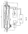
- FIG. 1 is a schematic view of a completely passive particulate converter system for stationary applications, illustrating exhaust flow according to the teachings of the present invention.
- FIG. 2 is a schematic view of the particulate converter system illustrating exhaust flow with emphasis on controlling exhaust gas re-circulation according to the teachings of the present invention.
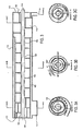
- FIG. 3 is a longitudinal cross-sectional view of the present particulate converter having a single agglomeration tube showing intake, agglomeration and separation, and outlet.
- FIG. 3A is a cross-sectional view taken along the line A-A of FIG. 3 .
- FIG. 3B is a cross-sectional view taken along the line B-B of FIG. 3 .
- FIG. 3C is a cross-sectional view taken along the line C-C of FIG. 3 .
- FIG. 4 is a longitudinal cross-sectional view of the present particulate converter having a two-stage separator and an incinerator integrated within the cylinder body.
- FIG. 4A is a cross-sectional view taken along the line A-A of FIG. 4 .
- FIG. 4B is a cross-sectional view taken along the line B-B of FIG. 4 .
- FIG. 4C is a cross-sectional view taken along the line C-C of FIG. 4 .
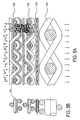
- FIGS. 5A and 5B show detailed cross-sectional views of the integrated incinerator knitted screen elements and the incineration process in progress.
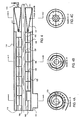
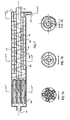
- FIG. 6 is a longitudinal cross-sectional view of a particulate converter having multiple agglomeration tubes.
- FIG. 6A is a cross-sectional view taken along the line A-A of FIG. 6 .
- FIG. 6B is a cross-sectional view taken along the line B-B of FIG. 6 .
- FIG. 6C is a cross-sectional view taken along the line C-C of FIG. 6 .
- FIG. 7 is a longitudinal cross-sectional view of a particulate converter having multiple agglomeration tubes and two-stage particle separator.
- FIG. 7A is a cross-sectional view taken along the line A-A of FIG. 7 .
- FIG. 7B is a cross-sectional view taken along the line B-B of FIG. 7 .
- FIG. 7C is a cross-sectional view taken along the line C-C of FIG. 7 .
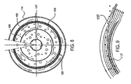
- FIG. 8 is a side view of an auger in the particle separator having multiple by-pass openings for noise attenuation.
- FIG. 9 is a cross-sectional view illustrating the window design and the principle of fugitive particle ejection and separation.
- FIG. 10 is a cross-sectional view of a composite wire mesh agglomerator.
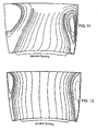
- FIG. 11 illustrates the analytical results of 2-micron particle migration as a function of flow travel within the centrifugal separator and the location of window openings, spacing between two consecutive arrow heads corresponds to migration resulting from a fall cyclonic rotational turn (360').
- the plot has been generated from a 3-dimensional fluid-mechanical analysis and highlights particle migration by size and the impact of swirl effect.
- FIG. 12 illustrates the analytical results of 5-micron particle migration within the centrifugal separator and the location of window openings. Spacing between two consecutive arrow heads corresponds to migration resulting from a full cyclonic rotational turn (360°).
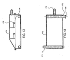
- FIG. 13 is a plan view of the soot collection chamber.
- FIG. 14 is a cross-sectional view of the soot collection chamber.
- FIG. 15 is a cross-sectional view of the soot collection chamber having an integrated incinerator.
- FIG. 16 is a plan view of the soot collection chamber having an integrated incinerator.
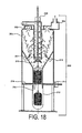
- FIG. 17 is a longitudinal cross-sectional view of soot processing drum with reverse pulse-jet.
- FIG. 18 is a modified cross-sectional view of soot processing drum with mechanical shaker.
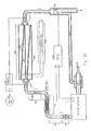
- FIG. 19 is a schematic view of a particulate converter and EGR system for mobile applications.
- FIG. 20 is a schematic view of a flattened quasi agglomeration-filtration particulate converter and EGR for mobile application, illustrating exhaust flow according to the teaching of the present invention.
- FIG. 21 is a schematic view of a flattened agglomeration-filtration particulate converter for mobile applications, illustrating exhaust flow with emphasis on different reverse pulse-jet scheme and the use of soot collection bag.
- FIG. 22 is a cross-sectional view of a cylindrical quasi agglomeration/filtrafion particulate converter for mobile applications.
- FIGS. 23 A and 23 B show the sliding door mechanism in the open and closed position, respectively.
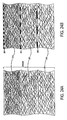
- FIGS. 24 A and 24 B are cross-sectional views of an agglomeration-filtration composite wire mesh media, and quasi fibrous and screen filtration media.
- FIG. 25 shows a passive incinerator arrangement in conjunction with particulate converters of FIGS. 20 and 22 .
- FIG. 26 is a control logic diagram for the control of reverse pulse-jet in a quasi agglomeration-filtration particulate converter.
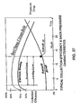
- FIG. 27 shows typical collection efficiency and back pressure characteristics of quasi wire mesh media with and without filtration screens.
- FIG. 28 is a logic diagram illustrating the principles employed for the capturing, disposal and destruction of VOCs, SO 2 and NO x .
- FIG. 1 of the drawings wherein reference numerals designate identical or corresponding parts throughout the several views, an after-treatment system for the reduction of pollutants from engine exhaust is illustrated.
- the system shown in FIG. 1 can be utilized for the after-treatment of exhaust gases from a variety of internal combustion engines operating at lean conditions and having appreciable amounts of particulate matter such as diesel engines, compressed and liquid natural gas engines.
- the system of the present invention can be designed to collectively destroy/separate/remove all pollutants from the exhaust gases. This includes: particulate matter and nano-size particles, volatile organic compounds, nitrogen oxide, hydrocarbon, carbon monoxide as well as sulfur dioxide.
- the exhaust gases released in the atmosphere can be stripped of all the stated pollutants at high efficiencies that can render such high polluting engines environmentally very clean.
- An oxidation catalyst 10 is connected to an engine exhaust manifold.
- the catalyst 10 can be either a diesel oxidation catalyst or active precious metal catalyst (as in gasoline engine applications).
- the exhaust system 50 designed to have maximum possible cooling of the exhaust gases before entering the particulate converter 100.
- the possible cooling modes can be generally divided into three segments representing different modes of heat transfer: a radiation segment 60, followed by an air convection segment 70, followed by a liquid convection segment 80.
- the particulate converter for stationary applications is shown in more detail in FIGS. 3 , 4 , and 6 .
- the particulate converter primarily consists of an intake section 110, an agglomerator 120, a centrifugal separator 130 and the outlet section 140.
- the outlet section 140 may employ an incinerator 150 as shown in FIGS. 4 and 5A. and 5B .
- the scavenger flow channel at the end of the converter is piped out to a soot collection chamber 170.
- the clean exhaust leaving the soot collection chamber 170 forms an exhaust gas re-circulation (EGR) 200 to the air cleaner of the engine.
- the EGR system may employ an axial boost pump 241 for proper metering of EGR flow.
- the soot collected in the soot collection chamber 170 Is piped out to soot processing drum 220 to reclaim soot in the form of pellets.
- Oxidation catalyst 10 of the present invention is selected to have sufficient reduction of the light fraction of the VOC compounds but to allow the heavy fraction of VOCs to pass through, condensate in the exhaust pipe and ultimately be collected in the particulate converter.
- the condensed fraction of the VOCs functions as. a bonding material that produces agglomerated particulates having large sizes and prevents breakdown due to turbulence or swirl phenomenon encountered in the cyclonic separator. Therefore, a smaller-size diesel oxidation catalyst is adequate for the purpose of the present invention.
- a diesel oxidization catalyst also is effective in oxidizing hydrocarbon, carbon monoxide and has a minor effect on the oxidization of sulfur dioxide (SO 2 ).
- an active precious-metal catalyst is highly effective in oxidizing hydrocarbon, carbon monoxide, and the light fraction of VOCs as well as the oxidization of SO 2 into sulfate compounds and NO to NO 2 at high efficiencies.
- Oxidation of SO 2 into sulfate is known industry-wide to be a very undesirable catalytic activity in diesel exhaust application since it results in an increased particulate emission.
- nano-size sulfate particles are formed which can be collected along with soot particles in the converter. The mixture of soot and sulfate forms wet brownish particles.
- this methodology can rid the exhaust gases of SO 2 pollution at high efficiencies. It should also be noted that NO can be oxidized to NO 2 at efficiencies in the range of approximately 50-70%. Since NO 2 is reactive, it can be absorbed along with sulfate compounds through scrubbing the exhaust with water after the converter.
- Devising means to cool exhaust gases varies according to engine application and the availability of liquid cooling media such as water.
- the approach of this invention is based on capitalizing on the properties of heat transfer modes.
- radiation exhaust section 60 is utilized as the exhaust gases leave the oxidization catalyst 10 at high temperatures.
- the radiation section 60 is characterized by having large surface area or larger pipe, and surface finish having the highest radiation characteristics such as matte black.
- This can be followed by an air/exhaust heat exchanger section 70.
- This section 70 relies on the relative speed of outside air passing across the exhaust pipe, due to vehicle movement.
- the exhaust pipe can be corrugated in the axial direction to expand the surface areas. Multiple pipes can also be used. All pipes need to be exposed to the wind factor.
- the last section is the liquid/exhaust heat exchanger 80.
- This section 80 relies on using liquids such as engine coolants, commonly used in automotives, or water, to provide the necessary cooling. It should be noticed that the exhaust temperatures of most diesel engines could reach approximately 900° - 1000°F at full load. Target exhaust temperature at the inlet to the converter is approximately 250°F to 300°F. Where abundant cooling is available, such as water, and NO 2 needs to be scrubbed, exhaust temperatures need to be lowered even further, to approximately 150°F to 200°F range after the converter. The selection of the three different cooling mechanisms varies to a great degree from one engine application to the other. Generally, the radiation section 60, by far, provides the highest cooling effect and is the least expensive. The second or third cooling mechanism can be used together or individually, dependent on the application.
- FIGS. 3 , 4 , 6 , and 7 further illustrate a preferred embodiment of the particulate converter 100.
- the intake segment 101 of the converter 100 diverts the incoming flow from a round or rectangular piping into the spacing between the housing 113 and the agglomerator 102 by gradually expanding the flow channel into the space feeding the agglomerator to minimize pressure drops.
- the agglomerator section 102 in the converter 100 can be either a single shell as shown in FIGS. 3 and 4 , or a multiple tube design as shown in FIGS. 6 and 7 . In both embodiments, a large surface area is needed to enhance the agglomeration efficiency.
- the multiple tube design of FIGS. 6 and 7 all flow is directed to the centrifugal separator.
- the flow is fed and processed on a continuous basis to the centrifugal separator. The amount of flow processed in each channel, therefore, is a fraction of the total flow.
- the amount of the flow in the channel can be selected. Processing a fraction of the total flow per channel is desirable since turbulence and swirl effects can be reduced. Further, the process of particulate separation through centrifugal action is limited to retain the particulates separated at the inside diameter of the agglomerator, while the clean exhaust stream migrates inwardly toward the inside core tube 107.
- the agglomerator is constructed from composite wire mesh media having variable wire sizes having packing densities as particularly shown in FIG. 24 A .
- the upstream side of the agglomerator 102 is made of coarse wire having low-packing density and progresses to finer wire having higher packing densities at the downstream side as shown in FIG 10 .
- Such selection criterion allows the capturing of large particulates on the outside layers while the smaller-size particulates are captured on the finer more packed wire. This strategy allows for maximum particle capturing efficiency and even soot loading distribution across the media while maintaining the pressure drop as low as possible.
- having open pores on the upstream side of the agglomerator allows the particles to be captured inside the agglomerator and prevents the build up of soot layers (cake) ahead of the agglomerator which could result in increasing the pressure drop.
- the process of agglomerating particulate matter is illustrated in FIG. 10 .
- the thickness of the agglomerator ranges from approximately 10mm to approximately 30mm and averages approximately 10mm to 20mm in most applications. This thickness, along with the build-up of soot dendrites in the void space between the wires, combined with low flow velocity, can result in the highest efficiencies of capturing sub-micron and nano-size particles from diesel exhaust having an order of reduction ranging from 10 4 to 10 5 of particle count. This drastically reduces a key component of exhaust toxic pollutant.
- the agglomerator of the present invention drastically contrasts with other known soot filter technologies, such as the ceramic wall-flow monolith where such devices have wall thickness averaging 0.1 mm to 0.3mm, rendering them less efficient in capturing sub-micron and nano-size particles.
- the nano-particles capturing efficiency is further enhanced through cooling of the exhaust gases. It is known that substantial amounts of nano-particles are formed during the cooling process of exhaust gases, and the maximum formation is reached when exhaust gases are cooled to ambient temperature. Cooling the exhaust gases from the 900°-1000°F range to approximately 250° - 300°F will result in forcing the condensation of a large numbers of nano-particles ahead of the converter.
- the centrifugal separators of the preferred embodiments of the present invention are shown in FIGS. 3 , 4 , and 7 .
- the centrifugal separator of FIG. 3 is constructed from one helical auger 105 mounted on concentric core (pipe) 111. Exhaust from the agglomerator is fed on a continuous and uniform basis throughout the length of the centrifugal separator.
- the concentric core pipe is equipped with windows 109 spaced equally along the flow path. The windows are spaced at about 120° apart along the auger rotational direction. To initiate rotational flow pattern, no windows are employed at the inlet to the auger.
- a cohersion baffle plate 103 is introduced which gradually builds up the flow into spiral motion.
- the cohersion plate gradually moves in the radial direction towards the inside core pipe. As such, the cohersion plate starts at the outside diameter and moves spirally toward the inside core. About 1.5 turns of auger rotation are needed to establish the full rotational flow channel. No windows are employed in this section of building up the rotational flow channel. The first window is employed 120° past the end of the cohersion plate to allow for particle separation in the exhaust layer adjacent to the core pipe. Thereafter, window-design captures clean layers of exhaust flow at a rate corresponding to the rate of incoming flow from the agglomerator. This allows the flow velocity in the flow channels to remain essentially constant.
- the selection of the startup section of the centrifugal separator and the location of the first window establishes the number of rotational cycles of the exhaust gases before entering the windows. Generally, about two rotational cycles are adequate for the separation of agglomerated particles having an approximate size over two (2) microns. Higher rotational cycles result in cleaner exhaust.
- FIGS. 11 and 12 illustrate typical particle separation (migration) through the centrifugal separator as a function of particle size vs. rotation.
- the particle migration for one full cyclonic turn (360° rotation) is represented by the path between two successive arrowheads.
- turbulence and swirl effect Two phenomena, however, create adverse effects on particle radial migration in the centrifugal separator: turbulence and swirl effect.
- turbulence and swirl effect Both have been investigated through 3-dimensional fluid-mechanics analysis employing aerosol modeling of particles having different sizes.
- the effect of swirl is dominant for smaller particles and can result in particle migration in the opposite direction of centrifugal direction, thus defying the targeted separation.
- swirl is limited to localized zones approximated as those adjacent to the two sides of the auger as shown in FIGS. 11 and 12 .
- the window opening therefore, is selected to stay clear from the swirl zones to avoid re-entering of contaminated exhaust inside the windows.
- a simple particle ejector 117 or separator is installed ahead of the window 107 as shown in FIG. 9 .
- centrifugal action will cause such particles to migrate radially a sufficient radial distance to avoid entering in the space of the window designated for clean flow. Due to particle inertia, these particles will establish a flow path separate from the flow stream entering the window. This phenomenon is referred to as non-isokinetic in aerosol science.
- Clean exhaust streams are entering the window openings on a progressive basis.
- the collected clean exhaust in the core pipe is released to the atmosphere. All agglomerated particles remain separated and are accumulated on a continuous basis at or near the outside diameter of the centrifugal separator.
- a portion of the exhaust gases carries all separated particles and are directed to an exit or to an electric incinerator. This portion of exhaust gases is referred to ' as scavenger flow.
- Exit mechanism is shown in the sectional views of FIGS. 3C , 6C and 7C .
- Cohersion spiral plate 112 is used to assist exiting the scavenger flow through outlet 116:
- an electrical incinerator 117 is employed as an integral component of the particulate converter, as shown in FIG. 4 , two tapered conical-shaped screen assemblies are connected at their ends to the inside core 111 and the outside shell 115, while the two mating ends are fastened together.
- This arrangement allows for high surface area needed to keep exhaust flow velocity low through the composite screen assembly.
- the scavenger flow is split between the.two conical screen assemblies. Surface area can be doubled by doubling the number of the conical screen assemblies (not shown).
- the composite screen assembly is shown in . 24A and 24B.
- the screens have different functions.
- the first screen (121)s selected to have large size knitted wires and wide openings.
- the downstream side of the screen 120 is coated with electrical insulating material such as a ceramic substance.
- This screen 120 is connected to either 12 or 24-volt power supply.
- the second screen is identical to the first screen (121) except that an electrical insulation is applied on the face matting with the first scree (121)
- the third screen 122 is the barrier screen and is selected to have openings less than 50 microns.
- the fourth screen 123 is a large-wire screen and is selected to provide structural support of the first three screens.
- the ceramic coating on the matting sides of the first and second screens provide double protection against short-circuiting of the screen metals.
- soot As the scavenger flow penetrates the screen assembly in the sequential order of this invention, agglomerated soot is collected on the outside surface of screen 122, which functions as a barrier.
- the soot particles continue to build up soot layers in the upstream direction until it reaches the first screen 120. Soot particles collected on the first and second screens 120 and 121 will come in contact with the bare metal of the two screens 120 and 121. Due to high electrical conductivity of soot, an electrical circuit is established and electric current flows through the soot layer. Soot is heated up to a high temperature in three to six seconds, and with the presence of oxygen in the scavenger flow, soot is incinerated very quickly.
- the bare metal of the second and third screens 121 and 122 may be coated with platinum.
- Precious metal coating will drastically improve the incineration process by lowering soot ignition temperature. Further, the presence of platinum coating maintains incineration process at high efficiency despite low oxygen content in the exhaust gases.
- the by-products of the incineration process are CO, CO 2 and steam, all of which are harmless gases and can pass through the third screen 122.
- Ash build up could potentially interfere with the function of the incinerator as it gradually builds up in the spacing between the first and second screens 120 and 121. Most ash is shaken off due to vibration and fall to a cavity at the bottom of the incinerator. Remaining ash that could clog the screen assembly can be removed through a routine maintenance procedure using backpressure pulsation.
- the incineration process takes place only on localized areas where soot build up reaches a point when an electrical circuit is formed. This renders the incineration process intermittent and somewhat continuous. Due to the very small flow velocity across the composite screens, high dispersion of soot loading over large area of the screen, small amounts of soot incinerated, thermal inertia of the first and second screens 120 and 121, the incineration process is considered to take place in a controlled environment. No appreciable increase in exhaust temperature would be observed between the upstream and the downstream side of the incinerator. Further, the material selected for the screens 121 and 122 is stainless steel having high corrosion-resistance at high temperature and high chemical-resistance against carbon and sulfur attacks. Selected specialty alloys having high nickel, chromium and aluminum such as a commercial grade known as alpha alloy are very adequate for the screen material.
- the scavenger flow leaving the converter employing an incinerator is clean of particulate matter and can be utilized as an exhaust gas re-circulation (EGR), and, therefore, is connected to the engine air intake after the air cleaner filter element. Vacuum pressure after the air cleaner is a sufficient drive to establish scavenger (EGR) flow.
- EGR exhaust gas re-circulation
- Such system arrangement is completely passive. However, EGR flow is small and non-controllable, and the ensuing reduction in NO x is small, 15-20% range. Further, when the engine is at idle conditions no EGR flow is established due to the very low negative pressure after the air filter element.
- soot collection chamber 170 is a simple chamber having one outlet at the bottom 171 for scavenger flow intake and a second outlet 173 at the upper side for clean exhaust exit. The clean exhaust leaving the chamber becomes exhaust gas re-circulation as described before.
- the soot chamber has two compartments separated by screen 174.
- the screen 174 functions as a soot barrier. Selecting the screen 174 to have a large surface area and having space void less than approximately 50 microns in addition to small scavenger flow results in very small flow velocity across the screen. This renders the screen 174 to function as a barrier to agglomerated soot. Soot builds up on the surface of the screen 174 in the form of layers (cake). As more layers of soot continue to build up on the downside of the screen, these layers ultimately fall down to the bottom of the chamber due to vehicle vibration and shock loadings.
- the soot chamber can be designed to collect soot-generated from three to six months of a truck operation dependant on engine soot emission level. Soot is collected in the bottom half of the chamber up to the screen.
- the chamber may employ an incinerator. Soot chamber incinerator consists of two rows of staggered stainless steel tubes coated with platinum, and is located at the bottom. The lower row is grounded and the higher row is connected to 12 or 24 volt power supply. Soot bridging the gap between grounded tube and power tube is incinerated on a continuous basis. Incinerators employed in the soot chamber are rugged and have simple design. Incinerator by-products are harmless gases that circulate to the engine air intake as part of the EGR system.
- Diesel applications where active platinum oxidation catalysts are employed will oxidize SO 2 to sulfate compounds, and soot collection should replace the incineration process. This is simply due to the fact that sulfate compounds cannot be incinerated. Re-circulation of sulfate compounds to the engine as part of the EGR can result in unwarranted damage to the intake system of the engine. This leads to a preferred embodiment in which soot is collected in the soot chamber and then is processed finally in a soot-processing drum 220 into soot pellets for ultimate sale as a commodity know as carbon black.
- Soot chamber 170 is emptied by connecting the second outlet 178 at the bottom of the chamber 170 to the soot processing drum 220, temporarily plug the tailpipe of the truck and operate the engine at close to idle conditions for about five minute.
- the engine exhaust flow will sweep the collected soot at the bottom of soot chamber 170 to the soot drum.
- FIGS. 17 and 18 Applications in which it is advantageous to collect the soot instead of incinerating it require the usage of a soot processing drum shown in FIGS. 17 and 18 .
- the function of the drum (220) is to separate and collect soot at the bottom of a cavity and compress it periodically until a compressed solid pellet is formed.
- the pellet is released into a container (plastic bag) for shipping and sale as a commodity to the chemical industry for applications such as printing. Sulfate and sulfuric acid are collected along with soot and the pellets can be brownish in color.
- the soot drum 200 is comprised of an intake flow distribution auger 201.
- Two or four concentric conical barrier screens 202 are installed in could take three to six months of truck operation, a soot-processing drum can serve a number of trucks as low as ten up to several hundreds.
- FIG. 18 Another preferred embodiment to release soot layers is a mechanical pulsator or shaker as shown in FIG. 18 .
- the mechanical shaker 218 provides adequate release of the soot cake off the screen 202.
- reverse pulse jet approach is desirable.
- the mechanical pulsator/shaker approach is preferred since it is simple and less expensive.
- the quasi agglomeration/filtration particulate converter is intended for mobile source applications.
- the particulate converter can have single or multiple chambers. Shown in FIG. 20 , is a converter with two chambers, which represents a preferred embodiment for the majority of under-the-floor mobile applications. In a two-chamber configuration, the intake flow is split into the two chambers. Each flow segment is directed to a composite wire mesh or a quasi composite wool and filtration screen media as shown in FIGS. 24A and 24B .
- the composite steel wool media is characterized as being an agglomerator media having low-pressure drop and low soot retention capacity. On the other hand, employing retaining screens having proper size openings will provide an added filtration function.
- the screens accumulate soot on the upstream side of the exhaust stream.
- the accumulated soot can form a cake.
- the flattened quasi agglomeration/filtration converter is shown in FIG. 19 has an intake 255 for the diversion and expansion of the incoming flow to the chamber(s).
- the chambers are separated by a separator plate 257.
- Each chamber has the quasi agglomeration/filtration media 258.
- a passive sliding door mechanism 265 is shown in FIG. 23 .
- the outlet 271 collects the the surrounding space.
- the backsides of screens 202 are connected to the outlet manifold 203.
- the outlet manifold 203 is connected to a vacuum booster blower 204, which is used to create sufficient vacuum to drive a minimum flow volume through the drum 200.
- the back pressure pulsation consists of a small compressor 205 delivering compressed air into an air tank 206.
- the air tank 206 is piped to the back of the screen 202 and the compressed air is released via a control valve 207.
- Valve 207 is activated periodically allowing pulses of high-pressure air to flow to the backside of the screens 202 releasing the soot cakes. The released soot drops to the bottom of the cavity.
- a spring loaded check valve 208 is employed to guard against bypassing of the pulsed air.
- a motor operated spindle 209 drives the compactor 210 downwards compressing the fallen soot into the cylindrical cavity until a certain calibrated load is reached.
- the motor stops and returns the compactor to the upward position ready for a second cycle.
- the pellet grows until it reaches a certain height.
- An electrical signal signifying a full pellet has been formed another motor-operated spindle 211 removes the bottom holding plate 213 away from the cavity.
- the compactor drives the pellet to the bottom platform 214. The pellet is released to the bag 212 for removal and shipping.
- a passive incinerator 280 embodiment B is shown in FIG. 25 .
- the quasi agglomeration/filtration media of FIG. 19 can be made in one or multiple layers having different design strategies.
- the upstream layers are designed to capture larger particulates.
- the downstream layers are designed to capture smaller-size particulates. This would result in an almost even soot loading throughout the media and lowers the back pressure build up versus soot loading.
- FIG. 24A and FIG. 24B show three layers of steel wool and three layers of steel wool and screens, respectively.
- Steel wool for the upstream layer has an average fiber diameter of 16-25 microns (also referred to as mean hydraulic fiber diameter) and can have a packing density of 3%-6% (packing density is defined as the percentage weight of steel wool to the solid steel weight of the same volume).
- the screen could have a mesh count (defined as the number of openings per inch) of 50x50 or 20x50. Subsequent layers will have smaller fiber diameter, higher packing density and higher mesh count per inch, such as 25-32 ⁇ m fiber diameter, 4% to 8% packing density and 75x75, 100x100 mesh or 40x100 mesh. Soot characterized as having high percentage of VOCs would require larger fiber size, lower packing density and lower screen mesh count to cope with the "gummy effect" which would increase the pressure drop.
- FIG. 22 Another preferred embodiment for a quasi agglomeration/filtration particulate converter is a round configuration as in FIG. 22 .
- the embodiment of the wire mesh media is based on cylindrical design in which the wire mesh is cylindrical, the separator sheets are cylindrical, and the housing is also cylindrical.
- the converter can also have one or multiple chambers. This embodiment is desirable in certain truck applications such as those having vertical mufflers.
- FIG. 22 shows a typical round configuration having two chambers. All elements and logic of the round embodiment are essentially the same as those of the flattened embodiment
- soot dendrites migrate in the flow stream direction.
- the downstream layer of the media becomes eventually loaded with soot, and beyond a certain threshold, soot will begin to blow off (as agglomerated particles).
- soot collection efficiency of the media begins to degrade and eventually it could have very low values.
- a reverse pulse jet is activated. This condition is triggered once a threshold value of pressure drop across the converter is reached.
- the reverse pulse jet is designed to blow off sufficient soot allowing the mesh media to unload the amount of accumulated soot.
- the blown off soot settles at the bottom of the chamber through gravity.
- a perforated screen can be inserted in the lower compartment of each chamber. Soot falls through the perforations in the screen.
- the exhaust flow is in a direction opposite to the direction of the pulsed air, and as such, exhaust flow can have a counter effect to that of the pulse jet.
- a sliding door can be used at the clean exhaust outlet of each chamber. The door closes temporarily for a fraction of a second up to two seconds during pulsation to ensure that all pulsed air will pass through the wire mesh media.
- the essential strategy of the control logic of the present invention is to dislodge the accumulated soot on the wire mesh media when a threshold value is reached, pulse the media, and bring it back to initial conditions to start another loading cycle.
- soot loading on the media can be measured through pressure drop measurement across the media.
- pressure drop is affected also with exhaust flow. Since it is desirable to limit pressure drop during vehicle operation, a simplified logic based on measurement of pressure drop is employed by employing a pressure switch. The pressure switch activates electric circuit when the threshold value is reached.
- Momentary high pressure drop is not representative of soot loading on the media. However, repeated high pressure drop during cyclic vehicle operation can be used as a measure of threshold soot loading in the media.
- the control logic therefore, is based on adding the durations when the threshold of high pressure drop is reached, and when the total time accumulation reaches a predetermined value, the control logic initiate the pulsation process.
- Typical values of the threshold value for high pressure drop are in the range of approximately 40 to 60 inches of water.
- Typical values of the threshold of accumulated time at and above the pressure threshold value can be in the range of three to five minutes.
- Typical control logic of the reverse pulse jet is shown in FIG. 26
- the first condition relates to engine RPM.
- Engine RPM has to close to idle or the engine is shut off. Since the pulsation process is less than one second, satisfying the low RPM condition is instantaneous, which can be simply accomplished once a vehicle comes to a stop.
- the second condition relates to the time required to refill the compressed air tank to pulse the next chamber. This time interval is two to ten minutes dependant on the source of the compressed air on the vehicle.
- the control logic diagram is shown in FIG. 26
- the incinerator most suitable for either the flattened or round embodiment is shown in FIG. 4 .
- the incinerator is composed of a series of plates electrically insulated from each other as well as alternatively charged.
- the plates can be solid plates or perforated plates. Further, it is desirable to have the plates constructed from high-temperature resistant stainless steel and coated with highly active catalyst such as platinum.
- the incinerator is activated once soot bridges the gap between adjacent plates having opposite charges. This allows high discharge of electric current which incinerates the soot quickly.
- the incinerator volume is sufficiently high to store ash, an incineration by-product. It is estimated that the Incinerator would require periodic disassembly and dumping of ash. Such clean up interval can be anywhere in the range of 25,000 to 150,000 miles of vehicle driving dependant on baseline particulate emission and driving cycles.
- Exhaust gas re-circulation as incorporated in the present invention resolves major problems commonly encountered with EGR In diesel applications.
- the first problem relates to the fact at idle and tow-load engine operating conditions, insufficient pressure across EGR terminals exists, which reduces the flow necessary for targeted NO x reduction. This condition is prevalent at idle and low engine loading conditions.
- Incorporating a high-efficiency axial flow booster blower (200) will resolve this problem. Blower delivers the necessary flow to achieve desired NOx reduction as well as to ensure continuous scavenger flow at all engine operating conditions.
- the blower 200 will throttle the EGR flow due to high-pressure differential across the EGR terminals, almost functioning as EGR control valve and therefore consuming virtually no power.
- idle and low engine loading conditions it has moderate electric power consumption.
- EGR flow is controlled through a simple control unit 242 having a logic based on engine RMP signal 243 and throttle position signal 244. This arrangement is most preferred for diesel retrofit applications.
- the EGR control logic is drastically simplified compared to OEM's logic.
- the EGR logic of the present invention is based on maximum NO x reduction and lowest fuel penalty, but would allow for any increase in visible emissions such as particulate, HC and CO. Increases in the visible baseline emissions and particulate are reduced through the converter system.
- EGR System for the quasi agglomeration/filtration converter employs a diverter valve 276.
- the diverter valve position is controlled by a signal from the ECU unit as shown in FIG. 20 .
- the diverter valve's unique design allows for the precise delivery of EGR flow by restricting the flow area to the tail pipe, and as such increases the pressure and in the EGR pipe to the engine air intake. EGR flow can be injected ahead of the intake air filter. This arrangement allows for even further removal of escaped agglomerated particles before entering the engine air intake system.
- the EGR strategy of the present invention resolves the major known problems associated with EGR and can be summarized as: (1) EGR flow is augmented and controlled by booster blower, (2) EGR flow is cleaned of pollutants that can foul or contaminate engine air intake system; and (3) the exhaust gases are cooled to a low temperature before entering the particulate converter. Return EGR lines provide additional cooling. The exhaust gases re-circulated back to the engine may be considered sub-cooled EGR that resolves problems associated with volumetric efficiency and engine performance.
- water is injected in the exhaust pipe after the converter to capture active NO 2 gases from the exhaust stream.
- the water scrubber can also capture sulfate compounds.
- Alkaline may be added to the water to enhance the capturing efficiency of NO 2 .
- FIGS. 1 and 2 are employed.
- Such system is comprised of small diesel oxidation catalyst, cooling exhaust piping and the particulate converter.
- VOCs and particulates are condensed in the forms of liquid or solid nano-particles. These particles are collected and agglomerated at high efficiencies in the agglomerator. Cooling pipes during engine warm up, provide little or insignificant cooling effect. At low engine-load and during idle conditions, exhaust temperature and flow are low.
- the cooling pipes provides the function of reducing the exhaust gas temperatures to targeted low temperature of 250 - 300 °F under subsequent engine operating conditions.
- Having exhaust cooled to 250-300°F range can reduce exhaust flows from full load by as much as 40%. Further, the reduction in exhaust gas viscosity can reach 40% by cooling the exhaust from 900-1000°F down to 300-250°F range.
- the net effect is a reduction in the pressure drop across the particulate converter by a factor as high as 3.1 compared to that of a converter without the cooling piping. This factor is critical to comply with engine maximum allowable back-pressure specifications and it results in lower fuel penalty. Since the converter can provide a sound attenuation function, replacing the muffler with the converter system, the backpressure in the two cases could be a wash. The net effect is no increase in fuel penalty where a muffler is replaced with the converter.
- Wire mesh agglomerators by far represent the most effective media in capturing submicron particles compared to other known filtration media.
- Particle capturing mechanisms in wire mesh media are grouped into three modes: inertial impaction, interception, and diffusion.
- the first two modes of collection are not effective for small particle sizes, but will have appreciable single fiber efficiency once particle size increases.
- Diesel exhaust is characterized by having very small particles averaging 0.1 microns and significantly high number of nano-size particles.
- the diffusion mode of particle collection emerges as being the dominant mode of capturing diesel soot particles. Small particles display considerable random diffusive motion called Brownian movement, collide with gas molecules and consequently tend to deviate from gas streamlines.
- Such particles are deposited on rigid surface such as fibrous surfaces or soot deposit between the fibers upon collision with such rigid surface.
- the equations representing the small particles single fiber collection efficiency (diffusion mode) and the overall collection efficiency are given in the formulas below:
- C Cunningham correction factor
- K b Boltzman constant
- T the absolute gas temperature
- ⁇ g the gas viscosity
- dp is the particle diameter
- ⁇ t 1 - EXP - 4 ⁇ ⁇ d ⁇ ⁇ H / ⁇ ⁇ d f
- ⁇ the fiber packing density
- H the filter thickness
- soot is blown off at certain location, in the agglomerator, such a condition is self-corrected.
- soot blows off more flow is rushed into that area and consequently higher soot build up takes place until equilibrium conditions with the balance of the media are reached.
- the back pressure across the particulate converter can increase by about 50% at prolonged idle conditions of five hours. When the engine speed increased from 800 RPM to 1100 RPM for five to ten seconds, the backpressure dropped by 40%. This is a self correcting mode for excessive soot build-up.
- the agglomerated particles can be directed to the electrical incinerator, where incineration takes place at soot build up reaching a threshold a point to an electrical circuit. Due to high electrical conductivity of the soot, a rush current heats the soot instantly. In the presence of oxygen in the exhaust, and the platinum coating on the incinerator screens, soot is incinerated at low temperature very quickly, typically in 3 to 5 seconds. Since incineration is localized and intermittent on the incinerator screen, the temperature rise downstream of the incinerator is insignificant. Also, due to the limited amount of soot incinerated at a given location, limited oxygen content in the exhaust and the very small exhaust velocity across the screens, the local temperature rise is moderate and would not result in damage to the screens.
- By-products of incineration are CO 2 , H 2 O and ash. Ash falls to the bottom of the incinerator cavity due to vibration and gravity. Since such cavity has large size, ash accumulation for the equivalent of 200,000 to 400,000 miles of driving can be stored before the cavity needs to be cleaned up. However, cleanup intervals of 150,000 to 200,000 miles are recommended.
- Exhaust gases leaving the incinerator are cleaned of particulate matter and are cool. They can be used as an EGR for moderate reduction in NO x emission. Should higher reduction in NO x emissions be desirable, a booster pump is used to increase and control EGR flow.
- the control logic of the booster pump takes into account maintaining scavenger flow at low engine loads and ensuring the proper amount of exhaust flow is re-circulated resulting in maximum reduction of NO x .
- controlled EGR flow is administered at all engine operating conditions. Absent from this EGR control logic is the minimization of particulate engine emission since the after-treatment system handles such excessive emission very effectively.
- an active platinum oxidation catalyst is recommended. This catalyst oxidizes SO 2 to sulfates and oxidizes 50-70% of NO to NO 2 dependent on exhaust temperatures. Sulfate can be collected along with particulate matter provided that the exhaust gases are cooled to temperatures below sulfate condensation temperature and are collected with particulates in the Converter. The exhaust gases leaving the converter can be scrubbed with water reducing exhaust temperatures to 200-150°F. This allows the capturing of reactive NO 2 gases by water. It would be desirable to add alkaline substances to the water. Dissolving of NO 2 in water will result in forming nitric acid.
- Such highly diluted portion of nitric acid has insignificant effect on large bodies of water, and could have beneficial effects in irrigation applications.
- sulfuric acid and particulates are collected in the soot chamber while the nitric acid portion is discharged and dissolved in water instead of being discharged in the air.
- the media needs to rejuvenate or regenerate to the initial condition equivalent to the beginning of the soot loading cycle, but with some soot still left in the composite media to maintain high soot collection efficiency.
- Typical collection efficiency and back pressure characteristic for the quasi media showing the effect of reverse pulse jet and the start of a new loading cycle are shown in FIG. 27 .
- the reverse pulse jet technique is most unique in that it lasts for a fraction of a second; it can be activated when the engine is off or at idling conditions. This allows for maximizing the effect of reverse pulse- jet since it flows in the opposite direction of exhaust flow. As such, exhaust flow weakens the effect of the reverse pulse- jet. Once pulse- jet is activated soot is blown off the media to upstream side; and the media is rejuvenated and ready for another cycle of soot filtration and collection.
- the converter is mounted with a slant to have the incinerator at the lowest point to assist with the migration of the soot to the incinerator cavity.
- Such a converter with an incinerator is expected to be a maintenance- free device requiring the cleanup of accumulated ashes every 150,000 to 200,000 miles.
- a converter having soot collection bag 272 as shown in FIG. 21 does not necessarily need an incinerator. Such converters also do not have to have the reverse pulse- jet system installed as an integral part of the converter. Rather, the pulse system can be stationary and serve multiple vehicles.
- the reverse pulse air system is activated through the exhaust tail pipe and the pulsed jet works on all converter chambers simultaneously.
- the bag size should be sufficient to expand to accommodate the volume of the pulsed air at ambient pressure.
- the pulsed air sweeps the soot collected at the bottom of the converter into the bag. For this type of operation, soot is swept into the bag during each reverse pulsation event. When the bag is loaded with soot, it would be replaced with an empty bag. It is estimated that bag replacement takes place every 6 to 30 months dependant on base line emission.
- Such system arrangement is attractive for the retrofit of mobile truck and bus application when the vehicles are housed in a maintenance garage at least once every week.
Applications Claiming Priority (3)
| Application Number | Priority Date | Filing Date | Title |
|---|---|---|---|
| US39847302P | 2002-07-25 | 2002-07-25 | |
| US45404603P | 2003-03-12 | 2003-03-12 | |
| EP03771748A EP1546515B1 (de) | 2002-07-25 | 2003-07-24 | Abgasnachbehandlungssystem zur verringerung von verunreinigungen aus dieselmotorabgas und verwandtes verfahren |
Related Parent Applications (2)
| Application Number | Title | Priority Date | Filing Date |
|---|---|---|---|
| EP03771748A Division EP1546515B1 (de) | 2002-07-25 | 2003-07-24 | Abgasnachbehandlungssystem zur verringerung von verunreinigungen aus dieselmotorabgas und verwandtes verfahren |
| EP03771748.5 Division | 2003-07-24 |
Publications (3)
| Publication Number | Publication Date |
|---|---|
| EP2078832A2 true EP2078832A2 (de) | 2009-07-15 |
| EP2078832A3 EP2078832A3 (de) | 2009-07-22 |
| EP2078832B1 EP2078832B1 (de) | 2010-11-03 |
Family
ID=31191209
Family Applications (2)
| Application Number | Title | Priority Date | Filing Date |
|---|---|---|---|
| EP08003513A Expired - Lifetime EP2078832B1 (de) | 2002-07-25 | 2003-07-24 | Abgasnachbehandlungssystem zur Minderung der Schadstoffe aus Dieselmotorabgas und damit verbundenes Verfahren |
| EP03771748A Expired - Lifetime EP1546515B1 (de) | 2002-07-25 | 2003-07-24 | Abgasnachbehandlungssystem zur verringerung von verunreinigungen aus dieselmotorabgas und verwandtes verfahren |
Family Applications After (1)
| Application Number | Title | Priority Date | Filing Date |
|---|---|---|---|
| EP03771748A Expired - Lifetime EP1546515B1 (de) | 2002-07-25 | 2003-07-24 | Abgasnachbehandlungssystem zur verringerung von verunreinigungen aus dieselmotorabgas und verwandtes verfahren |
Country Status (13)
| Country | Link |
|---|---|
| US (1) | US7266943B2 (de) |
| EP (2) | EP2078832B1 (de) |
| JP (2) | JP4413777B2 (de) |
| CN (2) | CN101881204B (de) |
| AT (2) | ATE387570T1 (de) |
| AU (1) | AU2003252127B2 (de) |
| BR (1) | BR0318291B1 (de) |
| CA (1) | CA2493161A1 (de) |
| DE (2) | DE60334868D1 (de) |
| HK (1) | HK1081250A1 (de) |
| MX (1) | MXPA05000988A (de) |
| RU (1) | RU2349767C2 (de) |
| WO (1) | WO2004011783A2 (de) |
Cited By (3)
| Publication number | Priority date | Publication date | Assignee | Title |
|---|---|---|---|---|
| WO2013148787A1 (en) * | 2012-03-28 | 2013-10-03 | Dearborn Financial, Inc. | Diesel emissions control after-treatment systems and related method |
| US8722002B2 (en) | 2011-09-06 | 2014-05-13 | Dearborn Financial, Inc. | System for recycling captured agglomerated diesel soot and related method |
| CN104331018A (zh) * | 2014-11-24 | 2015-02-04 | 永济新时速电机电器有限责任公司 | 5000m3/h绞吸式挖泥船用柴油机组一键启动控制装置 |
Families Citing this family (103)
| Publication number | Priority date | Publication date | Assignee | Title |
|---|---|---|---|---|
| DE202004011630U1 (de) * | 2004-07-24 | 2004-11-11 | Wabco Gmbh & Co.Ohg | Geräuschdämpfer für Drucklufteinrichtungen |
| US7462222B2 (en) * | 2004-10-05 | 2008-12-09 | Caterpillar Inc. | Filter service system |
| US7384455B2 (en) | 2004-10-05 | 2008-06-10 | Caterpillar Inc. | Filter service system and method |
| US7419532B2 (en) * | 2004-10-05 | 2008-09-02 | Caterpillar Inc. | Deposition system and method |
| US7410529B2 (en) | 2004-10-05 | 2008-08-12 | Caterpillar Inc. | Filter service system and method |
| DE602006014805D1 (de) * | 2005-03-18 | 2010-07-22 | Toyota Motor Co Ltd | Brennkraftmotorsteuervorrichtung und abgasreinigungsverfahren |
| US20070089501A1 (en) * | 2005-09-30 | 2007-04-26 | Endicott Dennis L | Method for monitoring exhaust gas condensates |
| US7468085B2 (en) * | 2005-12-19 | 2008-12-23 | Caterpillar Inc. | System and method for cleaning a filter |
| US7757481B2 (en) * | 2006-01-17 | 2010-07-20 | Cummins Filtration Ip, Inc | Enclosed volume exhaust diffuser apparatus, system, and method |
| US20080271448A1 (en) * | 2007-05-03 | 2008-11-06 | Ewa Environmental, Inc. | Particle burner disposed between an engine and a turbo charger |
| US7566423B2 (en) * | 2006-04-26 | 2009-07-28 | Purify Solutions, Inc. | Air purification system employing particle burning |
| US20070278199A1 (en) * | 2006-04-14 | 2007-12-06 | Ewa Environmental, Inc. | Particle burning in an exhaust system |
| US7500359B2 (en) * | 2006-04-26 | 2009-03-10 | Purify Solutions, Inc. | Reverse flow heat exchanger for exhaust systems |
| US20070240408A1 (en) * | 2006-04-14 | 2007-10-18 | Ewa Environmental, Inc. | Particle burner including a catalyst booster for exhaust systems |
| US20080314035A1 (en) * | 2006-04-14 | 2008-12-25 | Lincoln Evan-Beauchamp | Temperature Ladder and Applications Thereof |
| US7685814B2 (en) | 2006-07-12 | 2010-03-30 | Cummins Filtration, Inc. | Systems, apparatuses, and methods of determining plugging or deplugging of a diesel oxidation catalyst device |
| KR100792912B1 (ko) | 2006-11-13 | 2008-01-08 | 현대자동차주식회사 | 배기가스 나노입자 포집장치 및 방법 |
| US20090014423A1 (en) * | 2007-07-10 | 2009-01-15 | Xuegeng Li | Concentric flow-through plasma reactor and methods therefor |
| JP2008163809A (ja) * | 2006-12-27 | 2008-07-17 | Railway Technical Res Inst | エンジン |
| JP2010528228A (ja) * | 2007-05-25 | 2010-08-19 | ケムメル,レファート | ディーゼル排出微粒子状物質を処理するためのシステム及び方法 |
| JP2009012984A (ja) * | 2007-06-29 | 2009-01-22 | Ihi Corp | 発電設備における機能性材料の製造方法及び装置 |
| US8968438B2 (en) * | 2007-07-10 | 2015-03-03 | Innovalight, Inc. | Methods and apparatus for the in situ collection of nucleated particles |
| US8471170B2 (en) * | 2007-07-10 | 2013-06-25 | Innovalight, Inc. | Methods and apparatus for the production of group IV nanoparticles in a flow-through plasma reactor |
| WO2009051547A1 (en) * | 2007-08-24 | 2009-04-23 | Elsie Maria Hjelm | Device and method for elimination of particles from gaseous media |
| US8097055B2 (en) * | 2007-10-29 | 2012-01-17 | Caterpillar Inc. | System for treating exhaust gas |
| US8092563B2 (en) * | 2007-10-29 | 2012-01-10 | Caterpillar Inc. | System for treating exhaust gas |
| US7861511B2 (en) * | 2007-10-30 | 2011-01-04 | General Electric Company | System for recirculating the exhaust of a turbomachine |
| US8056318B2 (en) * | 2007-11-08 | 2011-11-15 | General Electric Company | System for reducing the sulfur oxides emissions generated by a turbomachine |
| US7874141B2 (en) * | 2007-11-16 | 2011-01-25 | General Electric Company | Auxiliary fluid source for an EGR purge system |
| DE102008011557B4 (de) * | 2007-12-12 | 2010-02-25 | GEA MASCHINENKüHLTECHNIK GMBH | Abgasrückkühler für eine Verbrennungskraftmaschine |
| US7886528B2 (en) * | 2008-02-29 | 2011-02-15 | Perkins Engines Company Limited | System for controlling exhaust aftertreatment |
| US8083822B2 (en) * | 2008-03-06 | 2011-12-27 | Caterpillar Inc. | System for treating exhaust gas |
| US8281579B2 (en) * | 2008-05-28 | 2012-10-09 | Caterpillar Inc. | Exhaust system having thermophoretic particulate agglomerator |
| JP2011202506A (ja) * | 2008-07-23 | 2011-10-13 | Kubota Corp | ディーゼルエンジン |
| DE102008038983A1 (de) * | 2008-08-13 | 2010-02-18 | Emitec Gesellschaft Für Emissionstechnologie Mbh | Partikelabfangvorrichtung für eine Abgasrückführleitung |
| US7926256B2 (en) | 2008-10-27 | 2011-04-19 | General Electric Company | Inlet system for an EGR system |
| US8549850B2 (en) * | 2008-10-31 | 2013-10-08 | Cummins Filtration Ip, Inc. | Exhaust gas aspirator |
| WO2010091490A1 (en) * | 2009-02-13 | 2010-08-19 | Miranda, Cristiane Nasser De | Device and method for filtration and depuration of exhaust gases from internal combustion engines |
| DE102010014037A1 (de) * | 2009-04-02 | 2010-11-04 | Cummins Filtration IP, Inc., Minneapolis | Reduktionsmittelzersetzungssystem |
| JP5033848B2 (ja) * | 2009-08-04 | 2012-09-26 | エヌ・イーケムキャット株式会社 | 船舶用排気ガス浄化装置、および排気ガス浄化方法 |
| GB2475317B (en) * | 2009-11-16 | 2015-03-18 | Gm Global Tech Operations Inc | Method for operating a diesel engine system |
| JP5420513B2 (ja) * | 2009-12-03 | 2014-02-19 | 日立建機株式会社 | 油圧作業機 |
| US20110146282A1 (en) * | 2009-12-18 | 2011-06-23 | General Electric Company | System and method for reducing sulfur compounds within fuel stream for turbomachine |
| JP5562697B2 (ja) * | 2010-03-25 | 2014-07-30 | 三菱重工業株式会社 | Dpfの再生制御装置、再生制御方法、および再生支援システム |
| JP2011208542A (ja) * | 2010-03-29 | 2011-10-20 | Toyota Motor Corp | 内燃機関の排気浄化装置 |
| JP5839784B2 (ja) * | 2010-06-02 | 2016-01-06 | ヤンマー株式会社 | 排気ガス浄化システム |
| US8071038B2 (en) * | 2010-06-09 | 2011-12-06 | Ford Global Technologies, Llc | Progressive catalyst loading for integrated particulate filter and selective catalytic reduction unit |
| WO2011163381A1 (en) * | 2010-06-22 | 2011-12-29 | Cummins Inc. | Particulate filter diagnostics |
| CN102011631A (zh) * | 2010-08-11 | 2011-04-13 | 张晓荣 | 一种火星熄灭装置 |
| JP4877415B2 (ja) * | 2010-12-09 | 2012-02-15 | トヨタ自動車株式会社 | 内燃機関の排気還流装置 |
| JP6041418B2 (ja) * | 2010-12-16 | 2016-12-07 | 臼井国際産業株式会社 | 重油以下の低質燃料を使用する大排気量船舶用ディーゼルエンジンの排気ガス浄化装置 |
| DE102011002936A1 (de) * | 2011-01-20 | 2012-07-26 | Ford Global Technologies, Llc | Partikelsensor, Abgassystem und Verfahren zum Bestimmen von Partikeln im Abgas |
| EP2675548B1 (de) * | 2011-02-14 | 2020-07-01 | Industrial Climate Solutions, Inc. | Verfahren zur Absorption einer Gaskomponente |
| CN102102562A (zh) * | 2011-03-16 | 2011-06-22 | 张晓荣 | 火星熄灭装置 |
| FR2974144A1 (fr) * | 2011-04-15 | 2012-10-19 | Renault Sa | Dispositif de compactage des suies d'un filtre a particules |
| JP5672139B2 (ja) * | 2011-05-11 | 2015-02-18 | トヨタ自動車株式会社 | 内燃機関のegrシステム |
| JP5673433B2 (ja) * | 2011-08-10 | 2015-02-18 | トヨタ自動車株式会社 | 内燃機関のegr装置 |
| DE102012000597A1 (de) * | 2012-01-14 | 2013-07-18 | Daimler Ag | Abgassystem einer Brennkraftmaschine und Verfahren zur Aufbereitung eines in Brennkraftmaschinenabgas eingebrachten Reduktionsmittels |
| CN104363750B (zh) * | 2012-01-27 | 2017-07-21 | N/C探索有限责任公司 | 用于促进土壤微生物和内燃的排放物产生的植物生长的碳纳米管的制造方法 |
| CN102536392B (zh) * | 2012-02-10 | 2013-08-07 | 徐和平 | 一种带旋转再生装置的柴油机尾气净化器 |
| US9146181B2 (en) * | 2012-07-27 | 2015-09-29 | Generel Electric Company | System and method for contaminant detection in fluid streams |
| US8584795B1 (en) * | 2012-09-04 | 2013-11-19 | Vac-Tron Equipment, Llc | Filter silencer |
| JP6056414B2 (ja) * | 2012-11-26 | 2017-01-11 | いすゞ自動車株式会社 | 排気ガス浄化システム及び排気ガス浄化方法 |
| GB2510171B (en) * | 2013-01-28 | 2015-01-28 | Cool Flame Technologies As | Method and cleaning apparatus for removal of SOx and NOx from exhaust gas |
| KR20210066946A (ko) * | 2013-04-26 | 2021-06-07 | 얀마 파워 테크놀로지 가부시키가이샤 | 작업 차량 |
| US9273648B2 (en) | 2013-07-26 | 2016-03-01 | Cnh Industrial America Llc | Air intake system for a work vehicle |
| CN104373175A (zh) * | 2013-08-14 | 2015-02-25 | 吴进森 | 汽车尾气高速离心滤碳机 |
| CN103629018B (zh) * | 2013-11-04 | 2015-11-18 | 江苏大学 | 一种egr冷却器的再生装置及再生方法 |
| CN103585811B (zh) * | 2013-11-26 | 2015-05-20 | 深圳市华星光电技术有限公司 | 过滤器 |
| WO2015081388A1 (en) * | 2013-12-06 | 2015-06-11 | Vapour Draw Systems Pty Ltd | System and method for improving combustion efficiency |
| CN103835787A (zh) * | 2014-03-17 | 2014-06-04 | 威海市天罡仪表股份有限公司 | 汽车尾气滤清消声器 |
| JP6238823B2 (ja) * | 2014-04-08 | 2017-11-29 | 臼井国際産業株式会社 | 高濃度に硫黄成分を含有する低質燃料を使用する船舶用ディーゼルエンジンの排ガス処理装置 |
| US9273649B2 (en) | 2014-05-30 | 2016-03-01 | Cnh Industrial America Llc | System and method for controlling an electric aspirator of an air intake system for a work vehicle |
| CN105797855B (zh) * | 2014-12-31 | 2017-06-23 | 北京纳米能源与系统研究所 | 一种气体净化装置 |
| US9416711B1 (en) * | 2015-02-26 | 2016-08-16 | Peter Lee Randall | Exhaust energy recovery and pollution control system for marine vessel |
| CN104791147A (zh) * | 2015-03-18 | 2015-07-22 | 上海交通大学 | 船用重型柴油机egr系统颗粒物去除装置 |
| CN106321195A (zh) * | 2015-06-17 | 2017-01-11 | 杨琦 | 一种柴油汽车金属颗粒捕集器的再生方法 |
| CA2989903C (en) * | 2015-06-17 | 2023-04-04 | N/C Quest Inc. | Emissions recycling using solubilizer equipment |
| US10184380B2 (en) * | 2015-12-01 | 2019-01-22 | Cummins Emission Solutions Inc. | Use of pressure differential in selective catalytic reduction systems |
| CN105909344B (zh) * | 2016-04-14 | 2018-08-31 | 三明学院 | 涡流区废气处理系统及方法 |
| CN105715551A (zh) * | 2016-04-15 | 2016-06-29 | 珠海格力电器股份有限公司 | 油分离器及其油分桶 |
| US10436091B2 (en) | 2016-06-02 | 2019-10-08 | Pollution Control Devices, Llc | Emission control device |
| WO2018020001A1 (de) * | 2016-07-29 | 2018-02-01 | Elringklinger Ag | Siebdichtung und verfahren zu deren betrieb |
| CN106139805B (zh) * | 2016-08-19 | 2017-12-05 | 山东蓬翔汽车有限公司 | 一种扫吸式清扫车的高效除尘滤尘装置 |
| CN109891168A (zh) | 2016-09-16 | 2019-06-14 | 开利公司 | 用于运输制冷系统的发动机排气冷却系统 |
| CN106555662B (zh) * | 2017-01-12 | 2018-04-24 | 钟艳琦 | 一种汽车尾气净化处理装置 |
| CN106555658B (zh) * | 2017-01-12 | 2018-09-04 | 临沂大学 | 汽车尾气监测及净化装置 |
| US10436090B2 (en) | 2017-03-22 | 2019-10-08 | Clean Diesel Development LLC | Soot separator for an internal combustion engine |
| USD870775S1 (en) | 2017-03-22 | 2019-12-24 | Clean Diesel Development LLC | Centrifugal separator |
| US10794309B2 (en) | 2017-10-18 | 2020-10-06 | Ford Global Technologies, Llc | Methods and systems for a particulate filter |
| FR3074885B1 (fr) * | 2017-12-13 | 2019-12-27 | Electricite De France | Procede d'evaluation du colmatage d'un echangeur thermique |
| CN108561212B (zh) * | 2018-03-06 | 2019-12-10 | 瑞立集团瑞安汽车零部件有限公司 | 一种汽车尾气处理装置 |
| GB2572986B (en) | 2018-04-18 | 2021-01-20 | Caterpillar Inc | Combined engine systems |
| CN109098819A (zh) * | 2018-07-28 | 2018-12-28 | 襄阳晟欣机电有限公司 | 一种具有废气回收利用的柴油机 |
| CN108815935A (zh) * | 2018-09-07 | 2018-11-16 | 浙江得亿制氧科技有限公司 | 一种可降温空气过滤器 |
| CN109372659A (zh) * | 2018-10-26 | 2019-02-22 | 江苏中远环保科技有限公司 | 一种控制循环冷却器中的节能环保装置 |
| CN109356686B (zh) * | 2018-11-05 | 2023-06-09 | 卢宝良 | 柴油发动机尾气黑烟净化器 |
| CN109372611B (zh) * | 2018-11-21 | 2020-09-04 | 南皮县绿源环保设备有限公司 | 一种汽车尾气专用过滤装置 |
| CN110242817A (zh) * | 2019-07-18 | 2019-09-17 | 西南石油大学 | 一种输气管道消声装置 |
| US11359996B2 (en) | 2019-11-14 | 2022-06-14 | Caterpillar Inc. | Soot measurement system |
| CN111006831B (zh) * | 2019-12-29 | 2022-06-24 | 万向通达股份公司 | 汽车排气系统模拟热振动试验装置 |
| US11484892B2 (en) | 2019-12-30 | 2022-11-01 | General Electric Company | Systems and methods for reducing particulate emissions |
| CN114832565B (zh) * | 2021-02-01 | 2023-05-30 | 西南交通大学 | 地下工程施工粉尘及有害气体智能化处理装置及方法 |
Citations (4)
| Publication number | Priority date | Publication date | Assignee | Title |
|---|---|---|---|---|
| US3815337A (en) | 1969-11-24 | 1974-06-11 | Ethyl Corp | Exhaust system |
| US4950313A (en) | 1988-01-05 | 1990-08-21 | University Of Waterloo | Fine dust removal device |
| WO1999013961A1 (en) | 1997-09-03 | 1999-03-25 | Converter Technology, Inc. | Continuous particle separation and removal cleaning system |
| US6007593A (en) | 1996-01-31 | 1999-12-28 | Dullien, Francis A.L. | Device for agglomerating and precipitating particles in a gas stream |
Family Cites Families (16)
| Publication number | Priority date | Publication date | Assignee | Title |
|---|---|---|---|---|
| US3162516A (en) * | 1961-08-14 | 1964-12-22 | Richard E Dwyer | Method of filtering exhaust gases |
| US3688476A (en) * | 1969-11-24 | 1972-09-05 | Ethyl Corp | Exhaust system |
| US3805520A (en) * | 1972-07-21 | 1974-04-23 | H Jones | Process and apparatus for reducing air pollution from internal combustion engines |
| DE3424196A1 (de) * | 1984-02-11 | 1985-08-22 | Robert Bosch Gmbh, 7000 Stuttgart | Einrichtung zur entfernung von festkoerperteilen aus abgasen von brennkraftmaschinen |
| US4720972A (en) * | 1986-10-17 | 1988-01-26 | Ford Motor Company | Low energy regeneration system for particulate trap for an internal combustion engine |
| US4969328A (en) * | 1986-10-21 | 1990-11-13 | Kammel Refaat A | Diesel engine exhaust oxidizer |
| US5121601A (en) * | 1986-10-21 | 1992-06-16 | Kammel Refaat A | Diesel engine exhaust oxidizer |
| DE8702501U1 (de) * | 1987-02-18 | 1987-07-23 | Gutermuth Sen., Paul, 6456 Langenselbold, De | |
| DE3731110A1 (de) * | 1987-09-16 | 1989-03-30 | Bosch Gmbh Robert | Koagulator fuer eine abgasreinigungsanlage von brennkraftmaschinen |
| DE3841182A1 (de) * | 1988-12-07 | 1990-06-13 | Bosch Gmbh Robert | Einrichtung zum entfernen von festkoerperpartikeln, insbesondere russteilchen, aus dem abgas von brennkraftmaschinen |
| US5251564A (en) * | 1990-04-26 | 1993-10-12 | Rim Julius J | Combustion box exhaust filtration system and method |
| JPH05195750A (ja) * | 1991-11-01 | 1993-08-03 | Kazuhiro Matsui | ディーゼルエンジンの排ガス中の煤塵除去装置 |
| JP3645704B2 (ja) * | 1997-03-04 | 2005-05-11 | トヨタ自動車株式会社 | 内燃機関の排気浄化装置 |
| US6138649A (en) * | 1997-09-22 | 2000-10-31 | Southwest Research Institute | Fast acting exhaust gas recirculation system |
| DE60131510T2 (de) * | 2000-03-27 | 2008-10-23 | Toyota Jidosha Kabushiki Kaisha, Toyota-shi | Abgasreinigungsvorrichtung |
| US6497095B2 (en) * | 2000-12-21 | 2002-12-24 | Ford Global Technologies, Inc. | Regeneration of diesel engine particulate filter only above low fuel levels |
-
2003
- 2003-07-24 BR BRPI0318291-6B1A patent/BR0318291B1/pt not_active IP Right Cessation
- 2003-07-24 EP EP08003513A patent/EP2078832B1/de not_active Expired - Lifetime
- 2003-07-24 MX MXPA05000988A patent/MXPA05000988A/es unknown
- 2003-07-24 DE DE60334868T patent/DE60334868D1/de not_active Expired - Lifetime
- 2003-07-24 AT AT03771748T patent/ATE387570T1/de not_active IP Right Cessation
- 2003-07-24 JP JP2004524727A patent/JP4413777B2/ja not_active Expired - Fee Related
- 2003-07-24 CN CN2010101506417A patent/CN101881204B/zh not_active Expired - Lifetime
- 2003-07-24 DE DE60319394T patent/DE60319394D1/de not_active Expired - Lifetime
- 2003-07-24 RU RU2005105567/06A patent/RU2349767C2/ru not_active IP Right Cessation
- 2003-07-24 CA CA002493161A patent/CA2493161A1/en not_active Abandoned
- 2003-07-24 EP EP03771748A patent/EP1546515B1/de not_active Expired - Lifetime
- 2003-07-24 AT AT08003513T patent/ATE487029T1/de not_active IP Right Cessation
- 2003-07-24 WO PCT/US2003/023048 patent/WO2004011783A2/en active IP Right Grant
- 2003-07-24 CN CN038176033A patent/CN1671954B/zh not_active Expired - Fee Related
- 2003-07-24 AU AU2003252127A patent/AU2003252127B2/en not_active Ceased
-
2005
- 2005-01-24 US US11/041,883 patent/US7266943B2/en not_active Expired - Fee Related
-
2006
- 2006-01-20 HK HK06100956.6A patent/HK1081250A1/xx not_active IP Right Cessation
-
2009
- 2009-09-17 JP JP2009215620A patent/JP2010031872A/ja active Pending
Patent Citations (4)
| Publication number | Priority date | Publication date | Assignee | Title |
|---|---|---|---|---|
| US3815337A (en) | 1969-11-24 | 1974-06-11 | Ethyl Corp | Exhaust system |
| US4950313A (en) | 1988-01-05 | 1990-08-21 | University Of Waterloo | Fine dust removal device |
| US6007593A (en) | 1996-01-31 | 1999-12-28 | Dullien, Francis A.L. | Device for agglomerating and precipitating particles in a gas stream |
| WO1999013961A1 (en) | 1997-09-03 | 1999-03-25 | Converter Technology, Inc. | Continuous particle separation and removal cleaning system |
Cited By (3)
| Publication number | Priority date | Publication date | Assignee | Title |
|---|---|---|---|---|
| US8722002B2 (en) | 2011-09-06 | 2014-05-13 | Dearborn Financial, Inc. | System for recycling captured agglomerated diesel soot and related method |
| WO2013148787A1 (en) * | 2012-03-28 | 2013-10-03 | Dearborn Financial, Inc. | Diesel emissions control after-treatment systems and related method |
| CN104331018A (zh) * | 2014-11-24 | 2015-02-04 | 永济新时速电机电器有限责任公司 | 5000m3/h绞吸式挖泥船用柴油机组一键启动控制装置 |
Also Published As
| Publication number | Publication date |
|---|---|
| RU2349767C2 (ru) | 2009-03-20 |
| US20050178111A1 (en) | 2005-08-18 |
| ATE387570T1 (de) | 2008-03-15 |
| EP1546515A2 (de) | 2005-06-29 |
| EP2078832B1 (de) | 2010-11-03 |
| CN101881204B (zh) | 2012-08-08 |
| EP2078832A3 (de) | 2009-07-22 |
| CN1671954B (zh) | 2010-05-26 |
| HK1081250A1 (en) | 2006-05-12 |
| JP2010031872A (ja) | 2010-02-12 |
| RU2005105567A (ru) | 2005-08-27 |
| JP4413777B2 (ja) | 2010-02-10 |
| CA2493161A1 (en) | 2004-02-05 |
| US7266943B2 (en) | 2007-09-11 |
| AU2003252127B2 (en) | 2009-06-18 |
| EP1546515A4 (de) | 2005-09-14 |
| AU2003252127A2 (en) | 2004-02-16 |
| BR0318291A (pt) | 2006-09-12 |
| DE60334868D1 (de) | 2010-12-16 |
| MXPA05000988A (es) | 2005-05-16 |
| BR0318291B1 (pt) | 2014-01-07 |
| DE60319394D1 (de) | 2008-04-10 |
| CN101881204A (zh) | 2010-11-10 |
| JP2005533963A (ja) | 2005-11-10 |
| WO2004011783A2 (en) | 2004-02-05 |
| ATE487029T1 (de) | 2010-11-15 |
| WO2004011783A3 (en) | 2004-07-01 |
| AU2003252127A1 (en) | 2004-02-16 |
| EP1546515B1 (de) | 2008-02-27 |
| CN1671954A (zh) | 2005-09-21 |
Similar Documents
| Publication | Publication Date | Title |
|---|---|---|
| EP1546515B1 (de) | Abgasnachbehandlungssystem zur verringerung von verunreinigungen aus dieselmotorabgas und verwandtes verfahren | |
| US5820833A (en) | Exhaust gas purifier | |
| KR100629208B1 (ko) | 배기 정화장치 | |
| RU2260469C2 (ru) | Ловушка для твердых частиц и способ отделения твердых частиц от потока текучей среды | |
| US4969328A (en) | Diesel engine exhaust oxidizer | |
| RU2392456C2 (ru) | Способ и устройство для очистки выхлопного газа | |
| EP0742352A2 (de) | Partikelfiltereinrichtung eines Dieselmotors | |
| KR20100039278A (ko) | 디젤엔진 배기가스의 미세 입자상 물질 처리 시스템 및 방법 | |
| Majewski | Diesel particulate filters | |
| JP2005535438A (ja) | リーンバーンエンジン用の排気機構 | |
| JP2587068B2 (ja) | ディ−ゼルエンジン排ガス中の微粒子処理装置 | |
| JP4567968B2 (ja) | 排ガス浄化装置及び排ガス浄化方法 | |
| Levendis et al. | Development of a self-cleaning particle trap for diesel engine particulate control | |
| JP2004108194A (ja) | 排気浄化装置 | |
| TWI304850B (en) | Exhaust after-treatment system for the reduction of pollutants from diesel engine exhaust and related method | |
| US11661872B2 (en) | Reduction of internal combustion engine emissions with improvement of soot filtration efficiency | |
| JP2003286819A (ja) | Pm浄化装置 | |
| JPH09324620A (ja) | ディーゼルエンジンの排ガス浄化装置 | |
| JPS6311292Y2 (de) | ||
| CN1161404A (zh) | 排气净化装置 | |
| CN108019254A (zh) | 用于优化废气系统再生和净化的方法 | |
| JP2003013725A (ja) | ディーゼルエンジン排ガスの粒子状物質除去装置 |
Legal Events
| Date | Code | Title | Description |
|---|---|---|---|
| PUAI | Public reference made under article 153(3) epc to a published international application that has entered the european phase |
Free format text: ORIGINAL CODE: 0009012 |
|
| PUAL | Search report despatched |
Free format text: ORIGINAL CODE: 0009013 |
|
| AC | Divisional application: reference to earlier application |
Ref document number: 1546515 Country of ref document: EP Kind code of ref document: P |
|
| AK | Designated contracting states |
Kind code of ref document: A2 Designated state(s): AT BE BG CH CY CZ DE DK EE ES FI FR GB GR HU IE IT LI LU MC NL PT RO SE SI SK TR |
|
| AK | Designated contracting states |
Kind code of ref document: A3 Designated state(s): AT BE BG CH CY CZ DE DK EE ES FI FR GB GR HU IE IT LI LU MC NL PT RO SE SI SK TR |
|
| 17P | Request for examination filed |
Effective date: 20100121 |
|
| AKX | Designation fees paid |
Designated state(s): AT BE BG CH CY CZ DE DK EE ES FI FR GB GR HU IE IT LI LU MC NL PT RO SE SI SK TR |
|
| GRAP | Despatch of communication of intention to grant a patent |
Free format text: ORIGINAL CODE: EPIDOSNIGR1 |
|
| GRAS | Grant fee paid |
Free format text: ORIGINAL CODE: EPIDOSNIGR3 |
|
| GRAA | (expected) grant |
Free format text: ORIGINAL CODE: 0009210 |
|
| AC | Divisional application: reference to earlier application |
Ref document number: 1546515 Country of ref document: EP Kind code of ref document: P |
|
| AK | Designated contracting states |
Kind code of ref document: B1 Designated state(s): AT BE BG CH CY CZ DE DK EE ES FI FR GB GR HU IE IT LI LU MC NL PT RO SE SI SK TR |
|
| REG | Reference to a national code |
Ref country code: GB Ref legal event code: FG4D |
|
| REG | Reference to a national code |
Ref country code: CH Ref legal event code: EP |
|
| REG | Reference to a national code |
Ref country code: IE Ref legal event code: FG4D |
|
| REF | Corresponds to: |
Ref document number: 60334868 Country of ref document: DE Date of ref document: 20101216 Kind code of ref document: P |
|
| REG | Reference to a national code |
Ref country code: SE Ref legal event code: TRGR |
|
| REG | Reference to a national code |
Ref country code: NL Ref legal event code: VDEP Effective date: 20101103 |
|
| PG25 | Lapsed in a contracting state [announced via postgrant information from national office to epo] |
Ref country code: PT Free format text: LAPSE BECAUSE OF FAILURE TO SUBMIT A TRANSLATION OF THE DESCRIPTION OR TO PAY THE FEE WITHIN THE PRESCRIBED TIME-LIMIT Effective date: 20110303 Ref country code: FI Free format text: LAPSE BECAUSE OF FAILURE TO SUBMIT A TRANSLATION OF THE DESCRIPTION OR TO PAY THE FEE WITHIN THE PRESCRIBED TIME-LIMIT Effective date: 20101103 Ref country code: SI Free format text: LAPSE BECAUSE OF FAILURE TO SUBMIT A TRANSLATION OF THE DESCRIPTION OR TO PAY THE FEE WITHIN THE PRESCRIBED TIME-LIMIT Effective date: 20101103 Ref country code: BG Free format text: LAPSE BECAUSE OF FAILURE TO SUBMIT A TRANSLATION OF THE DESCRIPTION OR TO PAY THE FEE WITHIN THE PRESCRIBED TIME-LIMIT Effective date: 20110203 Ref country code: AT Free format text: LAPSE BECAUSE OF FAILURE TO SUBMIT A TRANSLATION OF THE DESCRIPTION OR TO PAY THE FEE WITHIN THE PRESCRIBED TIME-LIMIT Effective date: 20101103 Ref country code: NL Free format text: LAPSE BECAUSE OF FAILURE TO SUBMIT A TRANSLATION OF THE DESCRIPTION OR TO PAY THE FEE WITHIN THE PRESCRIBED TIME-LIMIT Effective date: 20101103 |
|
| PG25 | Lapsed in a contracting state [announced via postgrant information from national office to epo] |
Ref country code: GR Free format text: LAPSE BECAUSE OF FAILURE TO SUBMIT A TRANSLATION OF THE DESCRIPTION OR TO PAY THE FEE WITHIN THE PRESCRIBED TIME-LIMIT Effective date: 20110204 |
|
| PG25 | Lapsed in a contracting state [announced via postgrant information from national office to epo] |
Ref country code: EE Free format text: LAPSE BECAUSE OF FAILURE TO SUBMIT A TRANSLATION OF THE DESCRIPTION OR TO PAY THE FEE WITHIN THE PRESCRIBED TIME-LIMIT Effective date: 20101103 Ref country code: CZ Free format text: LAPSE BECAUSE OF FAILURE TO SUBMIT A TRANSLATION OF THE DESCRIPTION OR TO PAY THE FEE WITHIN THE PRESCRIBED TIME-LIMIT Effective date: 20101103 Ref country code: BE Free format text: LAPSE BECAUSE OF FAILURE TO SUBMIT A TRANSLATION OF THE DESCRIPTION OR TO PAY THE FEE WITHIN THE PRESCRIBED TIME-LIMIT Effective date: 20101103 Ref country code: ES Free format text: LAPSE BECAUSE OF FAILURE TO SUBMIT A TRANSLATION OF THE DESCRIPTION OR TO PAY THE FEE WITHIN THE PRESCRIBED TIME-LIMIT Effective date: 20110214 |
|
| PG25 | Lapsed in a contracting state [announced via postgrant information from national office to epo] |
Ref country code: DK Free format text: LAPSE BECAUSE OF FAILURE TO SUBMIT A TRANSLATION OF THE DESCRIPTION OR TO PAY THE FEE WITHIN THE PRESCRIBED TIME-LIMIT Effective date: 20101103 Ref country code: SK Free format text: LAPSE BECAUSE OF FAILURE TO SUBMIT A TRANSLATION OF THE DESCRIPTION OR TO PAY THE FEE WITHIN THE PRESCRIBED TIME-LIMIT Effective date: 20101103 Ref country code: RO Free format text: LAPSE BECAUSE OF FAILURE TO SUBMIT A TRANSLATION OF THE DESCRIPTION OR TO PAY THE FEE WITHIN THE PRESCRIBED TIME-LIMIT Effective date: 20101103 |
|
| PLBE | No opposition filed within time limit |
Free format text: ORIGINAL CODE: 0009261 |
|
| STAA | Information on the status of an ep patent application or granted ep patent |
Free format text: STATUS: NO OPPOSITION FILED WITHIN TIME LIMIT |
|
| 26N | No opposition filed |
Effective date: 20110804 |
|
| PGFP | Annual fee paid to national office [announced via postgrant information from national office to epo] |
Ref country code: DE Payment date: 20110727 Year of fee payment: 9 Ref country code: GB Payment date: 20110725 Year of fee payment: 9 Ref country code: SE Payment date: 20110727 Year of fee payment: 9 Ref country code: FR Payment date: 20110830 Year of fee payment: 9 |
|
| REG | Reference to a national code |
Ref country code: DE Ref legal event code: R097 Ref document number: 60334868 Country of ref document: DE Effective date: 20110804 |
|
| PG25 | Lapsed in a contracting state [announced via postgrant information from national office to epo] |
Ref country code: IT Free format text: LAPSE BECAUSE OF FAILURE TO SUBMIT A TRANSLATION OF THE DESCRIPTION OR TO PAY THE FEE WITHIN THE PRESCRIBED TIME-LIMIT Effective date: 20101103 |
|
| PG25 | Lapsed in a contracting state [announced via postgrant information from national office to epo] |
Ref country code: MC Free format text: LAPSE BECAUSE OF NON-PAYMENT OF DUE FEES Effective date: 20110731 |
|
| REG | Reference to a national code |
Ref country code: CH Ref legal event code: PL |
|
| REG | Reference to a national code |
Ref country code: IE Ref legal event code: MM4A |
|
| PG25 | Lapsed in a contracting state [announced via postgrant information from national office to epo] |
Ref country code: LI Free format text: LAPSE BECAUSE OF NON-PAYMENT OF DUE FEES Effective date: 20110731 Ref country code: CH Free format text: LAPSE BECAUSE OF NON-PAYMENT OF DUE FEES Effective date: 20110731 |
|
| PG25 | Lapsed in a contracting state [announced via postgrant information from national office to epo] |
Ref country code: IE Free format text: LAPSE BECAUSE OF NON-PAYMENT OF DUE FEES Effective date: 20110724 |
|
| REG | Reference to a national code |
Ref country code: SE Ref legal event code: EUG |
|
| GBPC | Gb: european patent ceased through non-payment of renewal fee |
Effective date: 20120724 |
|
| REG | Reference to a national code |
Ref country code: FR Ref legal event code: ST Effective date: 20130329 |
|
| PG25 | Lapsed in a contracting state [announced via postgrant information from national office to epo] |
Ref country code: GB Free format text: LAPSE BECAUSE OF NON-PAYMENT OF DUE FEES Effective date: 20120724 Ref country code: FR Free format text: LAPSE BECAUSE OF NON-PAYMENT OF DUE FEES Effective date: 20120731 Ref country code: DE Free format text: LAPSE BECAUSE OF NON-PAYMENT OF DUE FEES Effective date: 20130201 Ref country code: SE Free format text: LAPSE BECAUSE OF NON-PAYMENT OF DUE FEES Effective date: 20120725 |
|
| REG | Reference to a national code |
Ref country code: DE Ref legal event code: R119 Ref document number: 60334868 Country of ref document: DE Effective date: 20130201 |
|
| PG25 | Lapsed in a contracting state [announced via postgrant information from national office to epo] |
Ref country code: LU Free format text: LAPSE BECAUSE OF NON-PAYMENT OF DUE FEES Effective date: 20110724 Ref country code: CY Free format text: LAPSE BECAUSE OF EXPIRATION OF PROTECTION Effective date: 20101103 |
|
| PG25 | Lapsed in a contracting state [announced via postgrant information from national office to epo] |
Ref country code: TR Free format text: LAPSE BECAUSE OF FAILURE TO SUBMIT A TRANSLATION OF THE DESCRIPTION OR TO PAY THE FEE WITHIN THE PRESCRIBED TIME-LIMIT Effective date: 20101103 |
|
| PG25 | Lapsed in a contracting state [announced via postgrant information from national office to epo] |
Ref country code: HU Free format text: LAPSE BECAUSE OF FAILURE TO SUBMIT A TRANSLATION OF THE DESCRIPTION OR TO PAY THE FEE WITHIN THE PRESCRIBED TIME-LIMIT Effective date: 20101103 |