EP2075425A1 - Schiebesitz sowie Rohranordnung und Abgasbehandlungseinrichtung - Google Patents
Schiebesitz sowie Rohranordnung und Abgasbehandlungseinrichtung Download PDFInfo
- Publication number
- EP2075425A1 EP2075425A1 EP08171378A EP08171378A EP2075425A1 EP 2075425 A1 EP2075425 A1 EP 2075425A1 EP 08171378 A EP08171378 A EP 08171378A EP 08171378 A EP08171378 A EP 08171378A EP 2075425 A1 EP2075425 A1 EP 2075425A1
- Authority
- EP
- European Patent Office
- Prior art keywords
- tube
- wire mesh
- fixed
- treatment device
- housing
- Prior art date
- Legal status (The legal status is an assumption and is not a legal conclusion. Google has not performed a legal analysis and makes no representation as to the accuracy of the status listed.)
- Granted
Links
Images


Classifications
-
- F—MECHANICAL ENGINEERING; LIGHTING; HEATING; WEAPONS; BLASTING
- F01—MACHINES OR ENGINES IN GENERAL; ENGINE PLANTS IN GENERAL; STEAM ENGINES
- F01N—GAS-FLOW SILENCERS OR EXHAUST APPARATUS FOR MACHINES OR ENGINES IN GENERAL; GAS-FLOW SILENCERS OR EXHAUST APPARATUS FOR INTERNAL-COMBUSTION ENGINES
- F01N3/00—Exhaust or silencing apparatus having means for purifying, rendering innocuous, or otherwise treating exhaust
- F01N3/02—Exhaust or silencing apparatus having means for purifying, rendering innocuous, or otherwise treating exhaust for cooling, or for removing solid constituents of, exhaust
- F01N3/021—Exhaust or silencing apparatus having means for purifying, rendering innocuous, or otherwise treating exhaust for cooling, or for removing solid constituents of, exhaust by means of filters
- F01N3/033—Exhaust or silencing apparatus having means for purifying, rendering innocuous, or otherwise treating exhaust for cooling, or for removing solid constituents of, exhaust by means of filters in combination with other devices
- F01N3/035—Exhaust or silencing apparatus having means for purifying, rendering innocuous, or otherwise treating exhaust for cooling, or for removing solid constituents of, exhaust by means of filters in combination with other devices with catalytic reactors
-
- F—MECHANICAL ENGINEERING; LIGHTING; HEATING; WEAPONS; BLASTING
- F01—MACHINES OR ENGINES IN GENERAL; ENGINE PLANTS IN GENERAL; STEAM ENGINES
- F01N—GAS-FLOW SILENCERS OR EXHAUST APPARATUS FOR MACHINES OR ENGINES IN GENERAL; GAS-FLOW SILENCERS OR EXHAUST APPARATUS FOR INTERNAL-COMBUSTION ENGINES
- F01N13/00—Exhaust or silencing apparatus characterised by constructional features
- F01N13/009—Exhaust or silencing apparatus characterised by constructional features having two or more separate purifying devices arranged in series
- F01N13/0097—Exhaust or silencing apparatus characterised by constructional features having two or more separate purifying devices arranged in series the purifying devices are arranged in a single housing
-
- F—MECHANICAL ENGINEERING; LIGHTING; HEATING; WEAPONS; BLASTING
- F01—MACHINES OR ENGINES IN GENERAL; ENGINE PLANTS IN GENERAL; STEAM ENGINES
- F01N—GAS-FLOW SILENCERS OR EXHAUST APPARATUS FOR MACHINES OR ENGINES IN GENERAL; GAS-FLOW SILENCERS OR EXHAUST APPARATUS FOR INTERNAL-COMBUSTION ENGINES
- F01N13/00—Exhaust or silencing apparatus characterised by constructional features
- F01N13/18—Construction facilitating manufacture, assembly, or disassembly
- F01N13/1805—Fixing exhaust manifolds, exhaust pipes or pipe sections to each other, to engine or to vehicle body
- F01N13/1811—Fixing exhaust manifolds, exhaust pipes or pipe sections to each other, to engine or to vehicle body with means permitting relative movement, e.g. compensation of thermal expansion or vibration
-
- F—MECHANICAL ENGINEERING; LIGHTING; HEATING; WEAPONS; BLASTING
- F01—MACHINES OR ENGINES IN GENERAL; ENGINE PLANTS IN GENERAL; STEAM ENGINES
- F01N—GAS-FLOW SILENCERS OR EXHAUST APPARATUS FOR MACHINES OR ENGINES IN GENERAL; GAS-FLOW SILENCERS OR EXHAUST APPARATUS FOR INTERNAL-COMBUSTION ENGINES
- F01N13/00—Exhaust or silencing apparatus characterised by constructional features
- F01N13/18—Construction facilitating manufacture, assembly, or disassembly
- F01N13/1805—Fixing exhaust manifolds, exhaust pipes or pipe sections to each other, to engine or to vehicle body
- F01N13/1827—Sealings specially adapted for exhaust systems
-
- F—MECHANICAL ENGINEERING; LIGHTING; HEATING; WEAPONS; BLASTING
- F01—MACHINES OR ENGINES IN GENERAL; ENGINE PLANTS IN GENERAL; STEAM ENGINES
- F01N—GAS-FLOW SILENCERS OR EXHAUST APPARATUS FOR MACHINES OR ENGINES IN GENERAL; GAS-FLOW SILENCERS OR EXHAUST APPARATUS FOR INTERNAL-COMBUSTION ENGINES
- F01N3/00—Exhaust or silencing apparatus having means for purifying, rendering innocuous, or otherwise treating exhaust
- F01N3/08—Exhaust or silencing apparatus having means for purifying, rendering innocuous, or otherwise treating exhaust for rendering innocuous
- F01N3/10—Exhaust or silencing apparatus having means for purifying, rendering innocuous, or otherwise treating exhaust for rendering innocuous by thermal or catalytic conversion of noxious components of exhaust
- F01N3/24—Exhaust or silencing apparatus having means for purifying, rendering innocuous, or otherwise treating exhaust for rendering innocuous by thermal or catalytic conversion of noxious components of exhaust characterised by constructional aspects of converting apparatus
- F01N3/28—Construction of catalytic reactors
- F01N3/2839—Arrangements for mounting catalyst support in housing, e.g. with means for compensating thermal expansion or vibration
- F01N3/2853—Arrangements for mounting catalyst support in housing, e.g. with means for compensating thermal expansion or vibration using mats or gaskets between catalyst body and housing
-
- F—MECHANICAL ENGINEERING; LIGHTING; HEATING; WEAPONS; BLASTING
- F01—MACHINES OR ENGINES IN GENERAL; ENGINE PLANTS IN GENERAL; STEAM ENGINES
- F01N—GAS-FLOW SILENCERS OR EXHAUST APPARATUS FOR MACHINES OR ENGINES IN GENERAL; GAS-FLOW SILENCERS OR EXHAUST APPARATUS FOR INTERNAL-COMBUSTION ENGINES
- F01N2310/00—Selection of sound absorbing or insulating material
- F01N2310/04—Metallic wool, e.g. steel wool, copper wool or the like
-
- F—MECHANICAL ENGINEERING; LIGHTING; HEATING; WEAPONS; BLASTING
- F01—MACHINES OR ENGINES IN GENERAL; ENGINE PLANTS IN GENERAL; STEAM ENGINES
- F01N—GAS-FLOW SILENCERS OR EXHAUST APPARATUS FOR MACHINES OR ENGINES IN GENERAL; GAS-FLOW SILENCERS OR EXHAUST APPARATUS FOR INTERNAL-COMBUSTION ENGINES
- F01N2310/00—Selection of sound absorbing or insulating material
- F01N2310/14—Wire mesh fabric, woven glass cloth or the like
-
- F—MECHANICAL ENGINEERING; LIGHTING; HEATING; WEAPONS; BLASTING
- F01—MACHINES OR ENGINES IN GENERAL; ENGINE PLANTS IN GENERAL; STEAM ENGINES
- F01N—GAS-FLOW SILENCERS OR EXHAUST APPARATUS FOR MACHINES OR ENGINES IN GENERAL; GAS-FLOW SILENCERS OR EXHAUST APPARATUS FOR INTERNAL-COMBUSTION ENGINES
- F01N2450/00—Methods or apparatus for fitting, inserting or repairing different elements
- F01N2450/30—Removable or rechangeable blocks or cartridges, e.g. for filters
-
- Y—GENERAL TAGGING OF NEW TECHNOLOGICAL DEVELOPMENTS; GENERAL TAGGING OF CROSS-SECTIONAL TECHNOLOGIES SPANNING OVER SEVERAL SECTIONS OF THE IPC; TECHNICAL SUBJECTS COVERED BY FORMER USPC CROSS-REFERENCE ART COLLECTIONS [XRACs] AND DIGESTS
- Y02—TECHNOLOGIES OR APPLICATIONS FOR MITIGATION OR ADAPTATION AGAINST CLIMATE CHANGE
- Y02T—CLIMATE CHANGE MITIGATION TECHNOLOGIES RELATED TO TRANSPORTATION
- Y02T10/00—Road transport of goods or passengers
- Y02T10/10—Internal combustion engine [ICE] based vehicles
- Y02T10/12—Improving ICE efficiencies
Definitions
- the present invention relates to a sliding seat for the axially movable mounting of a thermally loaded tube to a component, in particular in an exhaust system of an internal combustion engine.
- the invention also relates to a pipe arrangement in which at least one pipe with such a sliding seat is mounted on a carrier component.
- the present invention relates to an exhaust gas treatment device with such a pipe arrangement or with such a sliding seat.
- Thermally loaded pipes which are mounted by sliding fit on a support member, are used in many areas of technology, mainly where hot or cold fluids are transported in pipes. For example, this problem is found in heating systems, cooling systems and exhaust systems. Exhaust systems can be found in heaters and internal combustion engines, preferably in motor vehicles.
- an exhaust gas treatment device may include at least one tube which is mounted in a housing of the exhaust gas treatment device by means of such a sliding seat.
- An exhaust treatment device may, for example, be a particulate filter, a catalytic converter or a silencer or any combination of such devices.
- a conventional sliding seat may have some radial play between the tube and the respective receiving opening to facilitate the axial adjustability of the tube in the seat. This is unfavorable for applications which require a certain gastightness, since in principle a gas exchange is possible through the sliding seat. In particular, in an exhaust system with regard to sharper environmental regulations escape of exhaust gas into the environment, for example, by a sliding seat to avoid.
- the present invention is concerned with the problem of providing an improved embodiment for a sliding seat or for a pipe arrangement or for an exhaust gas treatment device, which is characterized in particular by the fact that in principle a certain sealing effect can be realized and / or that the mechanical load within the sliding seat is reduced ,
- the invention is based on the general idea to equip the respective sliding seat with a wire mesh, which is firmly attached on the one hand directly or indirectly to the respective component and on the other hand radially outwardly supported on the tube.
- the tube may shift along the wire mesh as its length changes due to thermal stress. Since such a wire mesh has a certain resilience, reduces the mechanical stress on the tube or the component within the sliding seat.
- an exhaust gas treatment device 1 comprises a housing 2 and at least one tube arrangement 3.
- the housing 2 has at least one inlet 4 and at least one outlet 5.
- the housing 2 has in the embodiment shown here two end floors 6 and 7 and an intermediate bottom 8.
- the first end floor 6 bounded with the intermediate bottom 8 in the housing 2 an inlet chamber 9.
- At the first end floor 6 of the inlet 4 is connected in the form of an inlet nozzle.
- the tube assembly 3 comprises at least two tubes communicating with each other, namely a first tube 10 and a second tube 11.
- the first tube 10 communicates on the input side with the inlet chamber 9 and on the output side with a deflection chamber 12.
- the first tube 10 is in an input section 13 on a support member fastened here by the housing 2 or by a part of the housing 2, namely formed here by the intermediate bottom 8 is.
- the first tube 10 with a sliding seat 15 also on the support member, that is supported on the housing 2, namely on the second end floor 7.
- the second tube 11 communicates on the input side with the deflection chamber 12 and the output side with a chamber 16, as a further Deflection chamber or can serve as a distribution chamber.
- an inlet 17 of the second tube 11 communicates with an outlet 18 of the first tube 10. Since the deflection chamber 12 connects the two tubes 10, 11 communicating with each other, it can also be referred to below as a connecting chamber 12.
- the second tube 11 is now supported in an input portion 19 with a sliding seat 20 on the support member, ie on the housing 2, especially on the second end floor 7.
- the second tube 11 in an output section 21 is likewise fastened to the carrier component, that is to say to the housing 2.
- the housing 2 for forming the chamber 16 includes a shell body 22 to which the second tube 11 is fixed in its output section 21.
- the first tube 10 has a first longitudinal central axis 23.
- the second tube 11 accordingly has a second longitudinal central axis 24.
- the two longitudinal central axes 23, 24 extend parallel to one another. Both tubes 10, 11 pass through the respective bottom 7 in separate openings.
- the connecting chamber 12 is hereby formed by one or more shell bodies 25, which are attached to the outlet section 14 of the first tube 10 and to the inlet section 19 of the second tube 11.
- said shell body 25 are grown on the second end floor 7.
- a bent connecting pipe is used to connect the two tubes 10, 11 together. Said connecting tube then connects the outlet 18 of the first tube 10 with the inlet 17 of the second tube 11.
- an exhaust gas treatment device 1 which can be used in an exhaust system of an internal combustion engine, this internal combustion engine can be located in particular in a motor vehicle, preferably in a commercial vehicle.
- the exhaust gas treatment device 1 is configured multifunctional here and contains at least one particle filter element 26, which is arranged in the first tube 10.
- the exhaust gas treatment device 1 here has at least one oxidation catalytic converter element 27, which is likewise arranged here in the first tube 10, namely expediently upstream of the particle filter element 26.
- the exhaust gas treatment device 1 can fulfill a silencer function.
- the first tube 10 here has a radially removable axial section 28, here by a brace is marked.
- Said axial section 28 is fastened by means of quick-fastening elements 41, for example in the form of clamps or the like, to the other sections of the first tube 10.
- quick-fastening elements 41 for example in the form of clamps or the like
- corresponding flanges may be formed, with which the fastening elements 41 cooperate.
- the particle filter element 26 is expediently arranged within the radially removable axial section 28. In this way, the respective particulate filter element 26 can be easily renewed or replaced, for example. Appropriately, the entire unit is exchanged from axial section 28 and particulate filter element 26 introduced therein.
- a third tube 29 is also provided, whose longitudinal central axis 30 can also be aligned parallel to the longitudinal central axes 23, 24 of the two other tubes 10, 11.
- An inlet 31 of the third tube 29 communicates with an outlet 32 of the second tube 11.
- the second tube 11 and the third tube 29 open into the chamber 16, so that this establishes the communicating connection between the two tubes 11, 29.
- the third pipe 29 may include at least one SCR catalyst 33.
- three such catalyst elements 33 in the third tube 29 are arranged one behind the other. With the help of such an SCR catalyst 33, a selective catalytic reduction of certain pollutants can be realized.
- the exhaust gas treatment device 1 also has a metering device 34, with the aid of which a liquid Educt can be introduced into the exhaust stream.
- a liquid Educt can be introduced into the exhaust stream.
- ammonia or urea or preferably an aqueous urea solution can be introduced into the exhaust gas flow with the aid of the metering device.
- Urea can be treated by a hydrolysis reaction to ammonia. With the help of ammonia, nitrogen oxides can be converted into nitrogen. The corresponding reactions take place in the SCR catalytic converter 33.
- the metering device 34 may be arranged or configured such that it introduces the respective educt in any case upstream of the SCR catalyst 33 in the exhaust gas stream. Expediently, the injection takes place downstream of the particle filter 26. In principle, the injection into the deflection chamber 12 can take place.
- the metering device 34 preferably introduces the educt into the inlet section 19 of the second tube 11. However, the injection of the reactant can also take place upstream of the second tube 11.
- the second tube 11 can serve as a mixing section for exhaust gas and introduced educt to realize an intensive mixing of exhaust gas and educt.
- the exhaust gas treatment device also has a fourth tube 35 which leads to the outlet 5 or which is connected to the exit 5 designed as outlet nozzle.
- An inlet 36 of the fourth tube 35 communicates with an outlet 37 of the third tube 29. This is achieved here by a further deflection chamber 38, with the help of a Shell body 39 and the second end floor 7 is realized.
- a longitudinal central axis 40 of the fourth tube 35 extends in the present case again parallel to the longitudinal center axes 23, 24 of the first tube 10 and the second tube 11th
- a single first tube 10, a single second tube 11, a single third tube 29 and a single fourth tube 35 can be seen in each case. It is clear that in particular embodiments at least one of said tubes 10, 11, 29, 35 can also be present multiple times.
- a plurality of second tubes 11 and / or a plurality of third tubes 29 may be provided with SCR catalysts 33.
- Corresponding Fig. 2 has the sliding seat 15, with which the first tube 10 is mounted on the support member 2 and the housing 2, a wire mesh 42.
- This knitted fabric 42 is arranged stationary with respect to the component 2, that is to say with respect to the housing 2, and is supported radially on the outside of the first tube 10.
- the tube 10 can thus move in its axial direction along the wire knit 42.
- the wire mesh 42 itself is fixed directly or indirectly on the housing 2.
- a knitted fabric 42 are basically such knitted wire in question, which can be used for fixing a catalyst element in a catalyst housing for use.
- Such knitted fabrics 42 are characterized by a comparatively high temperature resistance and by a certain spring elasticity.
- the respective seat 15 or 20 With the help of the wire mesh 42, the respective seat 15 or 20, the respective tube 10, 11 radially fix and still allow axial relative movements between the tube 10, 11 and housing 2 and second end floor 7.
- the knitted fabric 42 can consist of a plurality of knitted cushions distributed in the circumferential direction and spaced apart from one another.
- the knitted fabric 42 is in several parts, that is formed from several separate knitted cushions.
- the respective wire mesh 42 is preferably designed so that it consists of at least one knitted ring which includes the respective tube 10, 11 closed annularly in the circumferential direction.
- the Fig. 2 to 7 In each case only a single knitted cushion or a single knit ring is visible. If several knitted rings are present, these are expediently arranged axially next to one another.
- the respective sliding seat 15, 20 additionally equipped with a holder 43 which is fixed to the respective component 2, ie here on the housing 2 and at the bottom 7 thereof.
- Said holder 43 serves to fix the wire mesh 42 on the component 2, that is to say on the housing 2.
- the holder 43 may, for example, be of annular design and extend in the circumferential direction around the respective tube 10, 11.
- the holder 43 is distinguished in the embodiments of 3 and 4 by a U-profile, which forms a radially inwardly open annular groove, in which the wire mesh 42 is inserted.
- said holder 43 ' is virtually integrated into the component 2 or the housing 2, specifically by a corresponding shaping of the bottom 7 in the edge region of an unspecified opening, through which the respective tube 10, 11 is inserted through the bottom 7 ,
- the holder 43 formed by the fact that the component 2 is profiled in the region of the sliding seat 15, 20 for forming a receptacle which is completed with a cover 44 so as to form the holder 43".
- the wire mesh 42 has a rectangular or oval cross-section.
- the wire mesh 42 has a circular cross-section.
- the holder 43 or 43 in addition to a knitted fabric 42 acting radial support in the sliding seat 15, 20 realized, which works with a contact between holder 43, 43" and tube 10, 11.
- the radial support in the sliding seat 15, 20 exclusively on the wire mesh 42nd
- the embodiment according to Fig. 8 differs from the according to Fig. 1 only in that the deflection chamber 12 now extends over the entire height or side of the second end floor 7 or the exhaust gas treatment device 1. As a result, a reduction in the backpressure can be achieved.
- a cup-shaped lid body 45 is attached to the second end floor 7, so that the deflection chamber 12 is enclosed or bounded by the second end floor 7 and the lid body 45.
- forms in the embodiment according to Fig. 1 forms in the embodiment according to Fig. 1 the shell body 25 with thereof enclosed or limited deflection chamber 12 with respect to the second end floor 7 separate component.
- both the shell body 25, which is separate relative to the second end floor 7, for forming the deflection chamber 12 and the cover body 45 extending over the entire second end floor 7 and fastened thereto are provided.
- the deflection chamber 12 inside the exhaust treatment device 1 chambered twice, namely within the shell body 25 and within the lid body 45.
- the interior of the shell body 25 is gas-tight from the interior of the lid body 45 is separated.
- the lid body 45 together with the second end floor 7 form the space or the chamber 38, which deflects the exhaust gas from the third tube 29 into the fourth tube 35.
- the other shell body 39 which in the embodiments of Fig. 1 and 8th forms said deflection space 38 and encloses.
Landscapes
- Engineering & Computer Science (AREA)
- Chemical & Material Sciences (AREA)
- Combustion & Propulsion (AREA)
- Mechanical Engineering (AREA)
- General Engineering & Computer Science (AREA)
- Chemical Kinetics & Catalysis (AREA)
- Health & Medical Sciences (AREA)
- Toxicology (AREA)
- Exhaust Gas After Treatment (AREA)
- Gasket Seals (AREA)
- Exhaust Gas Treatment By Means Of Catalyst (AREA)
- Exhaust Silencers (AREA)
- Processes For Solid Components From Exhaust (AREA)
Abstract
Description
- Die vorliegende Erfindung betrifft einen Schiebesitz zur axial beweglichen Lagerung eines thermisch belasteten Rohrs an einem Bauteil, insbesondere in einer Abgasanlage einer Brennkraftmaschine. Die Erfindung betrifft außerdem eine Rohranordnung, bei der zumindest ein Rohr mit einem derartigen Schiebesitz an einem Trägerbauteil gelagert ist. Ferner betrifft die vorliegende Erfindung eine Abgasbehandlungseinrichtung mit einer solchen Rohranordnung beziehungsweise mit einem solchen Schiebesitz.
- Um thermisch belastete Rohre an einem Träger dauerhaft befestigen zu können, ist es üblich, das jeweilige Rohr einerseits mit einem Festlager und andererseits mit einem Loslager am jeweiligen Träger anzubringen, damit sich die Länge des Rohrs relativ zum Träger ändern kann, ohne dass dabei unzulässig hohe Spannungen zwischen Rohr und Träger auftreten. Zur Realisierung eines derartigen Loslagers können sogenannte Schiebesitze verwendet werden, bei denen das Rohr in einer im jeweiligen Träger ausgebildeten Aufnahmeöffnung sitzt, und zwar so, dass das Rohr bezüglich seiner Längsachse relativ zum Träger axial verstellbar ist.
- Thermisch belastete Rohre, die mittels Schiebesitz an einem Trägerbauteil gelagert werden, kommen in vielen Bereichen der Technik zur Anwendung, vorwiegend dort, wo heiße oder kalte Fluide in Rohren transportiert werden. Beispielsweise findet sich diese Problematik in Heizungsanlagen, Kühlanlagen und Abgasanlagen. Abgasanlagen finden sich bei Heizgeräten sowie bei Brennkraftmaschinen, vorzugsweise in Kraftfahrzeugen. Beispielsweise kann eine Abgasbehandlungseinrichtung zumindest ein Rohr enthalten, das in einem Gehäuse der Abgasbehandlungseinrichtung mit Hilfe eines solchen Schiebesitzes gelagert ist. Eine Abgasbehandlungseinrichtung kann beispielsweise ein Partikelfilter, ein Katalysator oder ein Schalldämpfer oder eine beliebige Kombination derartiger Einrichtungen sein.
- Ein herkömmlicher Schiebesitz kann zwischen dem Rohr und der jeweiligen Aufnahmeöffnung ein gewisses Radialspiel aufweisen, um die axiale Verstellbarkeit des Rohrs im Sitz zu erleichtern. Dies ist für Anwendungen, die eine gewisse Gasdichtigkeit erfordern, ungünstig, da durch den Schiebesitz hindurch grundsätzlich ein Gasaustausch möglich ist. Insbesondere bei einer Abgasanlage ist im Hinblick auf schärfere Umweltschutzbestimmungen ein Entweichen von Abgas in die Umgebung, beispielsweise durch einen Schiebesitz, zu vermeiden.
- Ferner besteht bei herkömmlichen Schiebesitzen grundsätzlich das Problem einer vergleichsweise hohen mechanischen Belastung des Rohrs beziehungsweise des jeweiligen Trägerteils innerhalb des Schiebesitzes. Mechanische Belastungen sind mit Verschleiß verbunden und können zu einer störenden Geräuschentwicklung führen.
- Die vorliegende Erfindung beschäftigt sich mit dem Problem, für einen Schiebesitz beziehungsweise für eine Rohranordnung beziehungsweise für eine Abgasbehandlungseinrichtung eine verbesserte Ausführungsform anzugeben, die sich insbesondere dadurch auszeichnet, dass grundsätzlich eine gewisse Dichtungswirkung realisierbar ist und/oder dass die mechanische Belastung innerhalb des Schiebesitzes reduziert ist.
- Dieses Problem wird erfindungsgemäß durch die Gegenstände der unabhängigen Ansprüche gelöst. Vorteilhafte Ausführungsformen sind Gegenstand der abhängigen Ansprüche.
- Die Erfindung beruht auf dem allgemeinen Gedanken, den jeweiligen Schiebesitz mit einem Drahtgestrick auszustatten, das einerseits direkt oder indirekt am jeweiligen Bauteil fest angebracht ist und das sich andererseits außen am Rohr radial abstützt. Im Betrieb kann sich das Rohr entlang des Drahtgestricks verschieben, wenn sich seine Länge aufgrund einer thermischen Belastung ändert. Da ein derartiges Drahtgestrick eine gewisse federelastische Nachgiebigkeit aufweist, reduziert sich die mechanische Belastung des Rohrs beziehungsweise des Bauteils innerhalb des Schiebesitzes.
- Gleichzeitig können radial orientierte Relativbewegungen zwischen Rohr und Bauteil gefedert beziehungsweise gedämpft werden, die beispielsweise aufgrund von Vibrationen im Betrieb auftreten können. Damit verbundene Geräusche lassen sich dadurch effektiv reduzieren.
- Weitere wichtige Merkmale und Vorteile der Erfindung ergeben sich aus den Unteransprüchen, aus den Zeichnungen und aus der zugehörigen Figurenbeschreibung anhand der Zeichnungen.
- Es versteht sich, dass die vorstehend genannten und die nachstehend noch zu erläuternden Merkmale nicht nur in der jeweils angegebenen Kombination, sondern auch in anderen Kombinationen oder in Alleinstellung verwendbar sind, ohne den Rahmen der vorliegenden Erfindung zu verlassen.
- Bevorzugte Ausführungsbeispiele der Erfindung sind in den Zeichnungen dargestellt und werden in der nachfolgenden Beschreibung näher erläutert, wobei sich gleiche Bezugszeichen auf gleiche oder ähnliche oder funktional gleiche Bauteile beziehen.
- Es zeigen, jeweils schematisch,
- Fig. 1
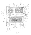
- einen stark vereinfachten Längsschnitt durch eine Abgasbehandlungseinrichtung,
- Fig. 2
- eine vergrößerte Darstellung eines Details der Abgasbehandlungseinrichtung im Bereich einer Rohranordnung,
- Fig. 3 bis 7
- stark vereinfachte vergrößerte Darstellungen der Rohranordnung im Bereich eines Schiebesitzes, bei unterschiedlichen Ausführungsformen,
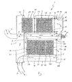
- Fig. 8 und 9
- jeweils einen Längsschnitt wie in
Fig. 1 , jedoch bei anderen Ausführungsformen. - Entsprechend
Fig. 1 umfasst eine Abgasbehandlungseinrichtung 1 ein Gehäuse 2 sowie zumindest eine Rohranordnung 3. Das Gehäuse 2 weist zumindest einen Eintritt 4 und wenigstens einen Austritt 5 auf. Das Gehäuse 2 besitzt in der hier gezeigten Ausführungsform zwei Endböden 6 und 7 sowie einen Zwischenboden 8. Der erste Endboden 6 begrenzt mit dem Zwischenboden 8 im Gehäuse 2 eine Eintrittskammer 9. An den ersten Endboden 6 ist der Eintritt 4 in Form eines Eintrittsstutzens angeschlossen. - Die Rohranordnung 3 umfasst zumindest zwei miteinander kommunizierende Rohre, nämlich ein erstes Rohr 10 und ein zweites Rohr 11. Das erste Rohr 10 kommuniziert eingangsseitig mit der Eintrittskammer 9 und ausgangsseitig mit einer Umlenkkammer 12. Das erste Rohr 10 ist in einem Eingangsabschnitt 13 an einem Trägerbauteil befestigt, das hier durch das Gehäuse 2 beziehungsweise durch einen Bestandteil des Gehäuses 2, nämlich hier durch den Zwischenboden 8 gebildet ist. In einem Ausgangsabschnitt 14 ist das erste Rohr 10 mit einem Schiebesitz 15 ebenfalls am Trägerbauteil, also am Gehäuse 2 gehaltert, und zwar am zweiten Endboden 7. Das zweite Rohr 11 kommuniziert eingangsseitig mit der Umlenkkammer 12 und ausgangsseitig mit einer Kammer 16, die als weitere Umlenkkammer oder als Verteilerkammer dienen kann. Über die Umlenkkammer 12 kommuniziert ein Eingang 17 des zweiten Rohrs 11 mit einem Ausgang 18 des ersten Rohrs 10. Da die Umlenkkammer 12 die beiden Rohre 10, 11 miteinander kommunizierend verbindet, kann sie im Folgenden auch als Verbindungskammer 12 bezeichnet werden. Das zweite Rohr 11 ist nun in einem Eingangsabschnitt 19 mit einem Schiebesitz 20 am Trägerbauteil, also am Gehäuse 2, speziell am zweiten Endboden 7 gehaltert. Außerdem ist das zweite Rohr 11 in einem Ausgangsabschnitt 21 ebenfalls am Trägerbauteil, also am Gehäuse 2 befestigt. Im vorliegenden Fall enthält das Gehäuse 2 zur Ausbildung der Kammer 16 einen Schalenkörper 22, an dem das zweite Rohr 11 in seinem Ausgangsabschnitt 21 befestigt ist.
- Das erste Rohr 10 weist eine erste Längsmittelachse 23 auf. Das zweite Rohr 11 weist dementsprechend eine zweite Längsmittelachse 24 auf. Bei der gezeigten Ausführungsform erstrecken sich die beiden Längsmittelachsen 23, 24 parallel zueinander. Beide Rohre 10, 11 durchsetzen den jeweiligen Boden 7 in separaten Öffnungen.
- Bei der hier gezeigten Ausführungsform münden der Ausgang 18 des ersten Rohrs 10 und der Eingang 17 des zweiten Rohrs 11 jeweils offen in der Verbindungskammer 12. Die Verbindungskammer 12 ist hier durch einen oder mehrere Schalenkörper 25 gebildet, die an den Ausgangsabschnitt 14 des ersten Rohrs 10 und an den Eingangsabschnitt 19 des zweiten Rohrs 11 angebaut sind. Alternativ ist auch eine Ausführungsform möglich, bei welcher besagte Schalenkörper 25 am zweiten Endboden 7 angebaut sind. Ebenso ist eine Ausführungsform möglich, bei welcher anstelle einer Verbindungskammer 12 ein gebogenes Verbindungsrohr verwendet wird, um die beiden Rohre 10, 11 miteinander zu verbinden. Besagtes Verbindungsrohr verbindet dann den Ausgang 18 des ersten Rohrs 10 mit dem Eingang 17 des zweiten Rohrs 11.
- Bei der hier gezeigten Ausführungsform handelt es sich um eine Abgasbehandlungseinrichtung 1, die in einer Abgasanlage einer Brennkraftmaschine zum Einsatz kommen kann, wobei sich diese Brennkraftmaschine insbesondere in einem Kraftfahrzeug, bevorzugt in einem Nutzfahrzeug, befinden kann. Die Abgasbehandlungseinrichtung 1 ist hier multifunktional ausgestaltet und enthält zumindest ein Partikelfilterelement 26, das im ersten Rohr 10 angeordnet ist. Zusätzlich weist die Abgasbehandlungseinrichtung 1 hier zumindest ein Oxidationskatalysatorelement 27 auf, das hier ebenfalls im ersten Rohr 10 angeordnet ist, und zwar zweckmäßig stromauf des Partikelfilterelements 26. Außerdem kann die Abgasbehandlungseinrichtung 1 eine Schalldämpferfunktion erfüllen.
- Das erste Rohr 10 besitzt hier einen radial herausnehmbaren Axialabschnitt 28, der hier durch eine geschweifte Klammer gekennzeichnet ist. Besagter Axialabschnitt 28 ist mittels Schnellbefestigungselementen 41, beispielsweise in Form von Schellen oder dergleichen, an den anderen Abschnitten des ersten Rohrs 10 befestigt. Hierzu können entsprechende Flansche ausgebildet sein, mit denen die Befestigungselemente 41 zusammenwirken. Das Partikelfilterelement 26 ist zweckmäßig innerhalb des radial herausnehmbaren Axialabschnitts 28 angeordnet. Auf diese Weise kann das jeweilige Partikelfilterelement 26 beispielsweise einfach erneuert oder ausgetauscht werden. Zweckmäßig wird dabei die gesamte Einheit aus Axialabschnitt 28 und darin eingebrachtem Partikelfilterelement 26 getauscht.
- Im Beispiel ist zudem ein drittes Rohr 29 vorgesehen, dessen Längsmittelachse 30 ebenfalls parallel zu den Längsmittelachsen 23, 24 der beiden anderen Rohre 10, 11 ausgerichtet sein kann. Ein Eingang 31 des dritten Rohrs 29 kommuniziert mit einem Ausgang 32 des zweiten Rohrs 11. Im Beispiel münden das zweite Rohr 11 und das dritte Rohr 29 in die Kammer 16, so dass diese die kommunizierende Verbindung zwischen den beiden Rohren 11, 29 herstellt. Das dritte Rohr 29 kann zumindest einen SCR-Katalysator 33 enthalten. Im Beispiel sind drei derartige Katalysatorelemente 33 im dritten Rohr 29 hintereinander angeordnet. Mit Hilfe eines derartigen SCR-Katalysators 33 lässt sich eine selektive katalytische Reduktion bestimmter Schadstoffe realisieren.
- Im Beispiel weist die Abgasbehandlungseinrichtung 1 außerdem eine Dosiereinrichtung 34 auf, mit deren Hilfe ein flüssiges Edukt in den Abgasstrom eingebracht werden kann. Zweckmäßig kann mit Hilfe der Dosiereinrichtung 34 Ammoniak oder Harnstoff oder bevorzugt eine wässrige Harnstofflösung in den Abgasstrom eingebracht werden. Harnstoff lässt sich durch eine Hydrolysereaktion zu Ammoniak aufbereiten. Mit Hilfe von Ammoniak lassen sich Stickoxide in Stickstoff umsetzen. Die entsprechenden Reaktionen laufen im SCR-Katalysator 33 ab.
- Die Dosiereinrichtung 34 kann so angeordnet beziehungsweise so ausgestaltet sein, dass sie das jeweilige Edukt jedenfalls stromauf des SCR-Katalysators 33 in den Abgasstrom einbringt. Zweckmäßig erfolgt die Eindüsung stromab des Partikelfilters 26. Grundsätzlich kann die Eindüsung in die Umlenkkammer 12 erfolgen. Bevorzugt bringt die Dosiereinrichtung 34 das Edukt in den Eingangsabschnitt 19 des zweiten Rohrs 11 ein. Die Eindüsung des Edukts kann jedoch auch stromauf des zweiten Rohrs 11 erfolgen. Das zweite Rohr 11 kann dabei als Mischstrecke für Abgas und eingebrachtes Edukt dienen, um eine intensive Durchmischung von Abgas und Edukt zu realisieren.
- Bei dem hier gezeigten Beispiel weist die Abgasbehandlungseinrichtung außerdem ein viertes Rohr 35 auf, das zum Austritt 5 führt beziehungsweise das mit dem als Austrittsstutzen ausgestalteten Austritt 5 verbunden ist. Ein Eingang 36 des vierten Rohrs 35 ist mit einem Ausgang 37 des dritten Rohrs 29 kommunizierend verbunden. Erreicht wird dies hier durch eine weitere Umlenkkammer 38, die mit Hilfe eines Schalenkörpers 39 und dem zweiten Endboden 7 realisiert ist. Eine Längsmittelachse 40 des vierten Rohrs 35 erstreckt sich im vorliegenden Fall wieder parallel zu den Längsmittelachsen 23, 24 des ersten Rohrs 10 beziehungsweise des zweiten Rohrs 11.
- In der hier gezeigten Schnittansicht der Abgasbehandlungseinrichtung 1 ist jeweils nur ein einziges erstes Rohr 10, ein einziges zweites Rohr 11, ein einziges drittes Rohr 29 und ein einziges viertes Rohr 35 erkennbar. Es ist klar, dass bei besonderen Ausführungsformen zumindest eines der genannten Rohre 10, 11, 29, 35 auch mehrfach vorhanden sein kann. Beispielsweise können mehrere zweite Rohre 11 und/oder mehrere dritte Rohre 29 mit SCR-Katalysatoren 33 vorhanden sein.
- Entsprechend
Fig. 2 weist der Schiebesitz 15, mit welcher das erste Rohr 10 am Trägerbauteil 2 beziehungsweise Gehäuse 2 gelagert ist, ein Drahtgestrick 42 auf. Dieses Drahtgestrick 42 ist bezüglich des Bauteils 2, also bezüglich des Gehäuses 2 ortsfest angeordnet und radial außen am ersten Rohr 10 abgestützt. Das Rohr 10 kann sich somit in seiner axialen Richtung entlang des Drahtgestricks 42 bewegen. Das Drahtgestrick 42 selbst ist direkt oder indirekt am Gehäuse 2 festgelegt. - Zusätzlich oder alternativ weist der Schiebesitz 20, mit dem das zweite Rohr 11 am Trägerbauteil 2 bzw. am Gehäuse 2 gelagert ist, ein Drahtgestrick 42 auf, das sich einerseits radial außen am zweiten Rohr 11 radial abstützt und das direkt oder indirekt am Bauteil 2 bzw. am Gehäuse 2 festgelegt ist.
- Als Drahtgestrick 42 kommen grundsätzlich solche Drahtgestricke in Frage, die zur Fixierung eines Katalysatorelements in einem Katalysatorgehäuse zur Anwendung kommen können. Derartige Drahtgestricke 42 zeichnen sich durch eine vergleichsweise hohe Temperaturbeständigkeit sowie durch eine gewisse Federelastizität aus. Mit Hilfe des Drahtgestricks 42 kann der jeweilige Sitz 15 beziehungsweise 20 das jeweilige Rohr 10, 11 radial fixieren und dennoch axiale Relativbewegungen zwischen Rohr 10, 11 und Gehäuse 2 beziehungsweise zweitem Endboden 7 zulassen.
- Grundsätzlich kann das Drahtgestrick 42 aus mehreren, in der Umfangsrichtung verteilt angeordneten, voneinander beabstandeten Gestrickkissen bestehen. Das Drahtgestrick 42 ist dabei mehrteilig, also aus mehreren separaten Gestrickkissen gebildet. Falls es jedoch auf eine gewisse Dichtigkeit im Schiebesitz 15 beziehungsweise 20 ankommt, ist das jeweilige Drahtgestrick 42 vorzugsweise so ausgestaltet, dass es zumindest aus einem Gestrickring besteht, der das jeweilige Rohr 10, 11 in Umfangsrichtung ringförmig geschlossen umfasst. Bei den hier gezeigten Ausführungsformen der
Fig. 2 bis 7 ist jeweils nur ein einzelnes Gestrickkissen beziehungsweise ein einzelner Gestrickring erkennbar. Sofern mehrere Gestrickringe vorhanden sind, sind diese zweckmäßig axial nebeneinander angeordnet. - Bei den Ausführungsformen der
Fig. 3 und 4 ist der jeweilige Schiebesitz 15, 20 zusätzlich mit einer Halterung 43 ausgestattet, die am jeweiligen Bauteil 2, also hier am Gehäuse 2 beziehungsweise an dessen Boden 7 befestigt ist. Besagte Halterung 43 dient zum Festlegen des Drahtgestricks 42 am Bauteil 2, also am Gehäuse 2. Die Halterung 43 kann beispielsweise ringförmig ausgestaltet sein und sich in Umfangsrichtung um das jeweilige Rohr 10, 11 erstrecken. Die Halterung 43 zeichnet sich bei den Ausführungsformen derFig. 3 und 4 durch ein U-Profil aus, das eine radial nach innen offene Ringnut bildet, in welche das Drahtgestrick 42 eingesetzt ist. - Bei der in
Fig. 5 gezeigten Ausführungsform ist besagte Halterung 43' quasi in das Bauteil 2 beziehungsweise das Gehäuse 2 integriert, und zwar hier durch eine entsprechende Formgebung des Bodens 7 im Randbereich einer nicht näher bezeichneten Öffnung, durch welche das jeweilige Rohr 10, 11 durch den Boden 7 hindurchgesteckt ist. - Bei den Ausführungsformen der
Fig. 6 und 7 ist die Halterung 43" dadurch ausgebildet, dass das Bauteil 2 im Bereich des Schiebesitzes 15, 20 zur Ausbildung einer Aufnahme profiliert ist, die mit einer Abdeckung 44 vervollständigt ist, um so die Halterung 43" zu bilden. - Bei den Ausführungsformen der
Fig. 3 und 4 besitzt das Drahtgestrick 42 einen rechteckigen oder ovalen Querschnitt. - Bei den Ausführungsformen der
Fig. 5 bis 7 besitzt das Drahtgestrick 42 einen kreisförmigen Querschnitt. Bei den Ausführungsformen derFig. 3 und 7 ist über die Halterung 43 beziehungsweise 43" eine zusätzlich zum Drahtgestrick 42 wirkende radiale Abstützung im Schiebesitz 15, 20 realisierbar, die mit einer Kontaktierung zwischen Halterung 43, 43" und Rohr 10, 11 arbeitet. Im Unterschied dazu erfolgt bei den Ausführungsformen derFig. 4 bis 6 die radiale Abstützung im Schiebesitz 15, 20 ausschließlich über das Drahtgestrick 42. - Die Ausführungsform gemäß
Fig. 8 unterscheidet sich von der gemäßFig. 1 lediglich dadurch, dass sich die Umlenkkammer 12 nunmehr über die gesamte Höhe oder Seite des zweiten Endbodens 7 bzw. der Abgasbehandlungseinrichtung 1 erstreckt. Hierdurch kann eine Absenkung des Gegendrucks erreicht werden. Zu diesem Zweck ist an den zweiten Endboden 7 ein schalenförmiger Deckelkörper 45 angebaut, so dass die Umlenkkammer 12 vom zweiten Endboden 7 und vom Deckelkörper 45 umschlossen bzw. begrenzt ist. Im Unterschied dazu bildet bei der Ausführungsform gemäßFig. 1 der Schalenkörper 25 mit davon umschlossener bzw. begrenzter Umlenkkammer 12 ein bezüglich des zweiten Endbodens 7 separates Bauteil. - Bei der Ausführungsform gemäß
Fig. 9 sind sowohl der bezüglich des zweiten Endbodens 7 separate Schalenkörper 25 zur Bildung der Umlenkkammer 12 als auch der sich über den gesamten zweiten Endboden 7 erstreckende und daran befestigte Deckelkörper 45 vorgesehen. Hierdurch ist die Umlenkkammer 12 innerhalb der Abgasbehandlungseinrichtung 1 doppelt gekammert, nämlich innerhalb des Schalenkörpers 25 und innerhalb des Deckelkörpers 45. Das Innere des Schalenkörpers 25 ist dabei gasdicht vom Inneren des Deckelkörpers 45 getrennt. Hierdurch kann der Deckelkörper 45 zusammen mit dem zweiten Endboden 7 den Raum bzw. die Kammer 38 bilden, die das Abgas vom dritten Rohr 29 in das vierte Rohr 35 umlenkt. Bei dieser Bauweise kann auf den anderen Schalenkörper 39 verzichtet werden, der bei den Ausführungsformen derFig. 1 und8 den genannten Umlenkraum 38 bildet bzw. umschließt.
Claims (14)
- Schiebesitz zur axial beweglichen Lagerung eines thermisch belasteten Rohrs (10, 11) an einem Bauteil (2), insbesondere in einer Abgasanlage einer Brennkraftmaschine, mit einem Drahtgestrick (42), das sich außen am Rohr (10) radial abstützt und das direkt oder indirekt am Bauteil (2) festgelegt ist.
- Schiebesitz nach Anspruch 1,
dadurch gekennzeichnet,
dass das Drahtgestrick (42) in einer Halterung (43) festgelegt ist, die am Bauteil (2) befestigt ist. - Schiebesitz nach Anspruch 1 oder 2,
dadurch gekennzeichnet,- dass das Drahtgestrick (42) aus mehreren in der Umfangsrichtung verteilt angeordneten voneinander beabstandeten Gestrickkissen besteht, oder- dass das Drahtgestrick (42) aus wenigstens einem das Rohr (10,11) in Umfangsrichtung ringförmig umfassenden Gestrickring besteht. - Rohranordnung, insbesondere in einer Abgasanlage einer Brennkraftmaschine,- mit wenigstens zwei thermisch belasteten, miteinander kommunizierenden Rohren (10, 11),- wobei ein erstes Rohr (10) in einem Eingangsabschnitt (13) an einem Trägerbauteil (2) befestigt ist,- wobei das erste Rohr (10) in einem Ausgangsabschnitt (14) mit einem Schiebesitz (15) am Trägerbauteil (2) gehaltert ist,- wobei ein zweites Rohr (11), dessen Eingang (17) mit einem Ausgang (18) des ersten Rohrs (10) kommunizierend verbunden ist, in einem Eingangsabschnitt (19) mit einem Schiebesitz (20) am Trägerbauteil (2) gehaltert ist,- wobei das zweite Rohr (11) in einem Ausgangsabschnitt (21) am Trägerbauteil (2) befestigt ist,- wobei zumindest einer der Schiebesitze (15, 20) ein Drahtgestrick (42) aufweist, das sich außen am jeweiligen Rohr (10, 11) radial abstützt und das direkt oder indirekt am Trägerbauteil (2) festgelegt ist.
- Rohranordnung nach Anspruch 4,
dadurch gekennzeichnet,
dass die Längsmittelachsen (23, 24) der beiden Rohre (10, 11) parallel zueinander verlaufen. - Rohranordnung nach Anspruch 4 oder 5,
dadurch gekennzeichnet,- dass ein gebogenes Verbindungsrohr vorgesehen ist, das den Ausgang (18) des ersten Rohrs (10) mit dem Eingang (17) des zweiten Rohrs (11) verbindet, oder- dass eine Verbindungskammer (12) vorgesehen ist, in welcher der Ausgang (18) des ersten Rohrs (10) und der Eingang (17) des zweiten Rohrs (11) offen münden. - Rohranordnung nach einem der Ansprüche 4 bis 6,
dadurch gekennzeichnet,
dass das Drahtgestrick (42) in einer Halterung (43) festgelegt ist, die am Trägerbauteil (2) befestigt ist. - Rohranordnung nach einem der Ansprüche 4 bis 7,
dadurch gekennzeichnet,- dass das Drahtgestrick (42) aus mehreren in der Umfangsrichtung verteilt angeordneten, voneinander beabstandeten Gestrickkissen besteht, oder- dass das Drahtgestrick (42) aus wenigstens einem das jeweilige Rohr (10, 11) in Umfangsrichtung ringförmig umfassenden Gestrickring besteht. - Abgasbehandlungseinrichtung, insbesondere für eine Abgasanlage einer Brennkraftmaschine,- mit einem Gehäuse (2), das zumindest einen Eintritt (4) und zumindest einen Austritt (5) aufweist,- mit einer Rohranordnung (3), die zumindest zwei miteinander kommunizierende Rohre (10, 11) aufweist,- wobei ein erstes Rohr (10) in einem Eingangsabschnitt (13) am Gehäuse (2) befestigt ist,- wobei das erste Rohr (10) in einem Ausgangsabschnitt (14) mit einem Schiebesitz (15) am Gehäuse (2) gehaltert ist,- wobei ein zweites Rohr (11), dessen Eingang (17) mit einem Ausgang (18) des ersten Rohrs (10) verbunden ist, in einem Eingangsabschnitt (19) mit einem Schiebesitz (20) am Gehäuse (2) gehaltert ist,- wobei das zweite Rohr (11) in einem Ausgangsabschnitt (21) am Gehäuse (2) befestigt ist,- wobei zumindest einer der Schiebesitze (15, 20) ein Drahtgestrick (42) aufweist, das sich außen am jeweiligen Rohr (10, 11) radial abstützt und das direkt oder indirekt am Gehäuse (2) festgelegt ist.
- Abgasbehandlungseinrichtung nach Anspruch 9,
dadurch gekennzeichnet,- dass das erste Rohr (10) wenigstens ein Partikelfilterelement (26) enthält, und/oder- dass das erste Rohr (10) wenigstens ein Oxidationskatalysatorelement (27) enthält, und/oder- dass das erste Rohr (10) einen radial herausnehmbaren Axialabschnitt (28) aufweist, und/oder- dass der radial herausnehmbare Axialabschnitt (28) das wenigstens eine Partikelfilterelement (26) enthält, und/oder- dass ein drittes Rohr (29) vorgesehen ist, dessen Eingang (31) mit einem Ausgang (32) des zweiten Rohrs (11) kommunizierend verbunden ist, und/oder- dass das dritte Rohr (29) wenigstens einen SCR-Katalysator (33) enthält, und/oder- dass eine Dosiereinrichtung (34) zum Einbringen eines flüssigen Edukts vorgesehen ist, und/oder- dass das zweite Rohr (11) als Mischstrecke für Abgas und eingebrachtes Edukt dient, und/oder- dass die Dosiereinrichtung (34) das Edukt in den Eingangsabschnitt (19) des zweiten Rohrs (11) einbringt, und/oder- dass ein viertes Rohr (35) vorgesehen ist, dessen Eingang (36) mit einem Ausgang (37) des dritten Rohrs (29) kommunizierend verbunden ist, und/oder- dass das vierte Rohr (35) zum Austritt (5) führt. - Abgasbehandlungseinrichtung nach Anspruch 9 oder 10,
dadurch gekennzeichnet,
dass die Längsmittelachsen (23, 24) des ersten Rohrs (10) und des zweiten Rohrs (11) parallel zueinander verlaufen. - Abgasbehandlungseinrichtung nach einem der Ansprüche 9 bis 11,
dadurch gekennzeichnet,- dass ein gebogenes Verbindungsrohr vorgesehen ist, das den Ausgang (18) des ersten Rohrs (10) mit dem Eingang (17) des zweiten Rohrs (11) verbindet, oder- dass eine Verbindungskammer (12) vorgesehen ist, in welcher der Ausgang (18) des ersten Rohrs (10) und der Eingang (17) des zweiten Rohrs (11) offen münden. - Abgasbehandlungseinrichtung nach einem der Ansprüche 9 bis 12,
dadurch gekennzeichnet,
dass das Drahtgestrick (42) in einer Halterung (43) festgelegt ist, die am Gehäuse (2) befestigt ist. - Abgasbehandlungseinrichtung nach einem der Ansprüche 9 bis 13,
dadurch gekennzeichnet,- dass das Drahtgestrick (42) aus mehreren in der Umfangsrichtung verteilt angeordneten, voneinander beabstandeten Gestrickkissen besteht, oder- dass das Drahtgestrick (42) aus wenigstens einem das jeweilige Rohr (10, 11) in Umfangsrichtung ringförmig umfassenden Gestrickring besteht.
Applications Claiming Priority (1)
| Application Number | Priority Date | Filing Date | Title |
|---|---|---|---|
| DE102007062663A DE102007062663A1 (de) | 2007-12-24 | 2007-12-24 | Schiebesitz sowie Rohranordnung und Abgasbehandlungseinrichtung |
Publications (2)
| Publication Number | Publication Date |
|---|---|
| EP2075425A1 true EP2075425A1 (de) | 2009-07-01 |
| EP2075425B1 EP2075425B1 (de) | 2012-10-24 |
Family
ID=40493274
Family Applications (1)
| Application Number | Title | Priority Date | Filing Date |
|---|---|---|---|
| EP08171378A Active EP2075425B1 (de) | 2007-12-24 | 2008-12-11 | Abgasbehandlungseinrichtung mit Rohranordnung und Schiebesitz |
Country Status (5)
| Country | Link |
|---|---|
| US (1) | US8322134B2 (de) |
| EP (1) | EP2075425B1 (de) |
| JP (1) | JP5379466B2 (de) |
| CN (1) | CN101476661B (de) |
| DE (1) | DE102007062663A1 (de) |
Families Citing this family (27)
| Publication number | Priority date | Publication date | Assignee | Title |
|---|---|---|---|---|
| JP4785803B2 (ja) * | 2007-08-02 | 2011-10-05 | 日野自動車株式会社 | 排気浄化装置 |
| DE102009014435A1 (de) * | 2009-03-26 | 2010-10-14 | J. Eberspächer GmbH & Co. KG | Abgasbehandlungseinrichtung |
| JP5519261B2 (ja) * | 2009-12-18 | 2014-06-11 | ヤンマー株式会社 | エンジン装置 |
| DE102010015271A1 (de) | 2010-04-15 | 2011-10-20 | J. Eberspächer GmbH & Co. KG | Abgasbehandlungseinrichtung |
| US8393147B2 (en) * | 2010-06-30 | 2013-03-12 | Caterpillar Inc. | Exhaust system having an aftertreatment module |
| DE102010034743A1 (de) | 2010-08-19 | 2012-02-23 | J. Eberspächer GmbH & Co. KG | Abgasreinigungsvorrichtung, Abgasanlage, Ausbauverfahren |
| US8609030B2 (en) | 2011-03-04 | 2013-12-17 | Tenneco Automotive Operating Company Inc. | Exhaust aftertreatment device with integrated shell and baffle |
| US8776509B2 (en) * | 2011-03-09 | 2014-07-15 | Tenneco Automotive Operating Company Inc. | Tri-flow exhaust treatment device with reductant mixing tube |
| DE102012214285A1 (de) * | 2012-08-10 | 2014-02-13 | Friedrich Boysen Gmbh & Co. Kg | Vorrichtung zum Führen eines Gasstroms |
| US9086007B2 (en) * | 2012-12-21 | 2015-07-21 | Caterpillar Inc. | System and method for accommodating aftertreatment bricks |
| US9599008B2 (en) * | 2013-01-10 | 2017-03-21 | Faurecia Emissions Control Technologies Usa, Llc | Thermal isolation disc for silencer |
| US8850801B2 (en) * | 2013-01-25 | 2014-10-07 | Caterpillar Inc. | Catalytic converter and muffler |
| WO2014167353A1 (en) | 2013-04-11 | 2014-10-16 | Perkins Engines Company Limited | Flowhood and emissions cleaning module |
| DE102015100994A1 (de) * | 2015-01-23 | 2016-07-28 | Faurecia Emissions Control Technologies, Germany Gmbh | Hitzeschildbaugruppe für eine Fahrzeugabgasanlage sowie Abgasanlagenbauteil eines Kraftfahrzeugs |
| US11136910B2 (en) | 2017-06-06 | 2021-10-05 | Cummins Emission Solutions Inc. | Systems and methods for mixing exhaust gases and reductant in an aftertreatment system |
| KR102395691B1 (ko) * | 2017-11-07 | 2022-05-09 | 바르실라 핀랜드 오이 | 내연 기관의 배기 시스템용 배기 가스 소음기 및 배기 시스템 |
| US10883411B2 (en) * | 2018-06-06 | 2021-01-05 | Ford Global Technologies, Llc | Systems and methods for an exhaust-gas aftertreatment device |
| US12503969B2 (en) | 2019-12-03 | 2025-12-23 | Cummins Emission Solutions Inc. | Reductant delivery system for exhaust gas aftertreatment system |
| CN120132644A (zh) | 2020-02-27 | 2025-06-13 | 康明斯排放处理公司 | 用于后处理系统中的混合器 |
| GB2631666A (en) * | 2020-10-22 | 2025-01-08 | Cummins Emission Solutions Inc | Exhaust gas aftertreatment system |
| GB2618011B (en) | 2021-02-02 | 2025-02-26 | Cummins Emission Solutions Inc | Exhaust gas aftertreatment systems |
| US12123337B2 (en) | 2021-03-18 | 2024-10-22 | Cummins Emission Solutions Inc. | Aftertreatment systems |
| CN117396668A (zh) | 2021-07-27 | 2024-01-12 | 康明斯排放处理公司 | 废气后处理系统 |
| CN119643152A (zh) | 2021-08-23 | 2025-03-18 | 康明斯排放处理公司 | 用于后处理系统的出口取样系统 |
| USD1042545S1 (en) | 2022-04-21 | 2024-09-17 | Cummins Emission Solutions Inc. | Aftertreatment system |
| USD1042544S1 (en) | 2022-04-21 | 2024-09-17 | Cummins Emission Solutions Inc. | Aftertreatment system |
| DE102023110142A1 (de) * | 2023-04-21 | 2024-10-24 | Purem GmbH | Modulartig aufgebaute Abgasbehandlungsanordnung |
Citations (9)
| Publication number | Priority date | Publication date | Assignee | Title |
|---|---|---|---|---|
| FR2617536A1 (fr) * | 1987-07-02 | 1989-01-06 | Dubois Jacques | Accouplement d'echappement a rotule |
| EP0537603A1 (de) * | 1991-10-18 | 1993-04-21 | Firma J. Eberspächer | Doppelwandiges luftisoliertes Rohr für Abgasanlagen in Fahrzeugen |
| EP0580963A1 (de) * | 1992-07-27 | 1994-02-02 | Witzenmann GmbH Metallschlauch-Fabrik Pforzheim | Rohrgelenk |
| DE4318343A1 (de) * | 1993-06-02 | 1994-12-08 | Iwk Regler Kompensatoren | Vorrichtung zum Dämpfen von Schwingungen in einer Abgasanlage eines Fahrzeugs |
| DE19929423A1 (de) * | 1998-07-01 | 2000-01-05 | Bayerische Motoren Werke Ag | Schalldämpfer einer Kraftfahrzeug-Abgasanlage |
| DE19918301C1 (de) * | 1999-04-22 | 2000-10-26 | Zeuna Staerker Kg | Teilsystem einer Abgasanlage für ein Kraftfahrzeug |
| DE10021494A1 (de) * | 2000-01-28 | 2001-08-09 | Dnv Inc | Flexibler Entkoppler für Auspuffleitungen bei Kraftfahrzeugen |
| EP1329608A2 (de) * | 2002-01-22 | 2003-07-23 | Faurecia Abgastechnik GmbH | Abgasanlage für Kraftfahrzeuge |
| WO2006117468A1 (fr) * | 2005-05-04 | 2006-11-09 | Faurecia Systemes D'echappement | Collecteur a double coque |
Family Cites Families (42)
| Publication number | Priority date | Publication date | Assignee | Title |
|---|---|---|---|---|
| US2070543A (en) * | 1936-01-13 | 1937-02-09 | Hayes Ind Inc | Muffler |
| US3690406A (en) * | 1970-12-04 | 1972-09-12 | Leopold Weiss | Exhaust noise silencer |
| JPS5146205B2 (de) * | 1972-07-03 | 1976-12-08 | ||
| US3903987A (en) * | 1973-02-20 | 1975-09-09 | Tenneco Inc | Muffler housing |
| US4188783A (en) * | 1977-08-10 | 1980-02-19 | Suzuki Jidosha Kogyo Kabushiki Kaisha | Exhaust gas purification device |
| FR2499151B1 (fr) * | 1981-02-02 | 1985-12-13 | Peugeot Cycles | Coupelle de fermeture pour silencieux d'echappement automobile et silencieux comportant une telle coupelle |
| US4735283A (en) * | 1986-12-04 | 1988-04-05 | Tenneco Inc. | Muffler with flow director plates |
| CA1262869A (en) * | 1988-06-23 | 1989-11-14 | Glen Knight | Combined muffler and catalytic converter exhaust unit |
| DE9205294U1 (de) * | 1992-04-16 | 1992-06-17 | Heinrich Gillet GmbH & Co KG, 6732 Edenkoben | Abgasanlage für Kraftfahrzeuge |
| EP0662564B2 (de) * | 1994-01-07 | 2001-09-26 | J. Eberspächer GmbH & Co. | Luftspaltisoliertes Abgasrohr und Verfahren zu seiner Herstellung |
| JPH084524A (ja) | 1994-06-20 | 1996-01-09 | Calsonic Corp | 曲り二重排気装置及びその製造工法 |
| JPH0828257A (ja) * | 1994-07-11 | 1996-01-30 | Toyota Motor Corp | 二重排気管 |
| IT1280969B1 (it) * | 1995-10-13 | 1998-02-11 | Coral Spa | Dispositivo di depurazione dei gas di scarico di un motore a combustione interna |
| JP3557925B2 (ja) * | 1998-12-22 | 2004-08-25 | トヨタ自動車株式会社 | 内燃機関の排気浄化装置 |
| JP4132489B2 (ja) * | 1999-10-19 | 2008-08-13 | 本田技研工業株式会社 | マフラー構造 |
| ATE291154T1 (de) * | 1999-12-09 | 2005-04-15 | Eminox Ltd | Vorrichtung zur behandlung von gasstrom |
| US6543575B1 (en) * | 2000-06-14 | 2003-04-08 | Lindab Ab | Double-walled structure and connection arrangement |
| DE10042542A1 (de) * | 2000-08-30 | 2002-03-14 | Eberspaecher J Gmbh & Co | Abgasreinigungssystem für Kraftfahrzeuge, insbesondere Diesel-Nutzfahrzeuge |
| JP3943818B2 (ja) * | 2000-09-21 | 2007-07-11 | 本田技研工業株式会社 | エンジンの消音器 |
| JP2002227640A (ja) * | 2001-02-02 | 2002-08-14 | Sankei Kogyo Kk | 排気ガス浄化装置 |
| DE10105841C2 (de) * | 2001-02-07 | 2002-12-12 | Benteler Automobiltechnik Gmbh | Abgasleitung mit Luftspaltisolierung für eine Brennkraftmaschine |
| JP3992948B2 (ja) * | 2001-07-02 | 2007-10-17 | 本田技研工業株式会社 | ジェット推進艇の排気構造 |
| JP2004162610A (ja) | 2002-11-13 | 2004-06-10 | Sakamoto Industry Co Ltd | 曲がり二重排気管 |
| US6832473B2 (en) * | 2002-11-21 | 2004-12-21 | Delphi Technologies, Inc. | Method and system for regenerating NOx adsorbers and/or particulate filters |
| JP2004183622A (ja) * | 2002-12-06 | 2004-07-02 | Honda Motor Co Ltd | 内燃機関の排気消音器 |
| MY141622A (en) * | 2003-06-19 | 2010-05-31 | Yamaha Motor Co Ltd | Exhaust system for an engine |
| DE10334307B4 (de) * | 2003-07-28 | 2008-06-26 | Benteler Automobiltechnik Gmbh | Isolierte Abgasleitung |
| US7229597B2 (en) * | 2003-08-05 | 2007-06-12 | Basfd Catalysts Llc | Catalyzed SCR filter and emission treatment system |
| JP2007510094A (ja) * | 2003-10-27 | 2007-04-19 | ウエスタートビーク コーポレーション | 排気物質の低減のためのエンジン制御システム |
| JP4395360B2 (ja) * | 2003-11-27 | 2010-01-06 | 日野自動車株式会社 | 排気浄化装置 |
| US7051523B2 (en) * | 2004-03-10 | 2006-05-30 | General Motors Corporation | Exhaust system assemblies employing wire bushings for thermal compensation |
| DE102004021474B3 (de) * | 2004-04-30 | 2005-03-10 | Audi Ag | Vorrichtung zur Aufhängung eines dyanmisch beanspruchten Funktionsteiles |
| WO2006029199A1 (en) * | 2004-09-08 | 2006-03-16 | Donaldson Company, Inc. | Joint for an engine exhaust system component |
| JP3715985B1 (ja) * | 2004-10-29 | 2005-11-16 | 日産ディーゼル工業株式会社 | 液体還元剤噴射ノズル構造 |
| JP2006151298A (ja) * | 2004-11-30 | 2006-06-15 | Honda Motor Co Ltd | 燃料電池自動車 |
| DE102005002289B4 (de) * | 2005-01-17 | 2007-04-19 | J. Eberspächer GmbH & Co. KG | Abgasbehandlungssystem |
| JP4546310B2 (ja) * | 2005-03-31 | 2010-09-15 | 川崎重工業株式会社 | 自動二輪車用エンジンの排気システム |
| DE102005025045A1 (de) * | 2005-05-30 | 2006-12-14 | J. Eberspächer GmbH & Co. KG | Abgasanlage |
| JP2007040149A (ja) * | 2005-08-02 | 2007-02-15 | Mitsubishi Fuso Truck & Bus Corp | 内燃機関の排気浄化装置 |
| US7650965B2 (en) * | 2006-06-09 | 2010-01-26 | Emcon Technologies Llc | Exhaust system |
| US7717205B2 (en) * | 2006-11-28 | 2010-05-18 | Caterpillar Inc. | Engine hood assembly enclosure with exhaust aftertreatment device integrated therein, and machine using same |
| JP4785766B2 (ja) * | 2007-02-09 | 2011-10-05 | 日野自動車株式会社 | 排気浄化装置 |
-
2007
- 2007-12-24 DE DE102007062663A patent/DE102007062663A1/de not_active Withdrawn
-
2008
- 2008-12-11 EP EP08171378A patent/EP2075425B1/de active Active
- 2008-12-17 US US12/337,256 patent/US8322134B2/en active Active
- 2008-12-22 JP JP2008324857A patent/JP5379466B2/ja active Active
- 2008-12-24 CN CN200810187555.6A patent/CN101476661B/zh active Active
Patent Citations (9)
| Publication number | Priority date | Publication date | Assignee | Title |
|---|---|---|---|---|
| FR2617536A1 (fr) * | 1987-07-02 | 1989-01-06 | Dubois Jacques | Accouplement d'echappement a rotule |
| EP0537603A1 (de) * | 1991-10-18 | 1993-04-21 | Firma J. Eberspächer | Doppelwandiges luftisoliertes Rohr für Abgasanlagen in Fahrzeugen |
| EP0580963A1 (de) * | 1992-07-27 | 1994-02-02 | Witzenmann GmbH Metallschlauch-Fabrik Pforzheim | Rohrgelenk |
| DE4318343A1 (de) * | 1993-06-02 | 1994-12-08 | Iwk Regler Kompensatoren | Vorrichtung zum Dämpfen von Schwingungen in einer Abgasanlage eines Fahrzeugs |
| DE19929423A1 (de) * | 1998-07-01 | 2000-01-05 | Bayerische Motoren Werke Ag | Schalldämpfer einer Kraftfahrzeug-Abgasanlage |
| DE19918301C1 (de) * | 1999-04-22 | 2000-10-26 | Zeuna Staerker Kg | Teilsystem einer Abgasanlage für ein Kraftfahrzeug |
| DE10021494A1 (de) * | 2000-01-28 | 2001-08-09 | Dnv Inc | Flexibler Entkoppler für Auspuffleitungen bei Kraftfahrzeugen |
| EP1329608A2 (de) * | 2002-01-22 | 2003-07-23 | Faurecia Abgastechnik GmbH | Abgasanlage für Kraftfahrzeuge |
| WO2006117468A1 (fr) * | 2005-05-04 | 2006-11-09 | Faurecia Systemes D'echappement | Collecteur a double coque |
Also Published As
| Publication number | Publication date |
|---|---|
| JP5379466B2 (ja) | 2013-12-25 |
| DE102007062663A1 (de) | 2009-06-25 |
| US20090158721A1 (en) | 2009-06-25 |
| JP2009174521A (ja) | 2009-08-06 |
| EP2075425B1 (de) | 2012-10-24 |
| US8322134B2 (en) | 2012-12-04 |
| CN101476661A (zh) | 2009-07-08 |
| CN101476661B (zh) | 2013-07-03 |
Similar Documents
| Publication | Publication Date | Title |
|---|---|---|
| EP2075425B1 (de) | Abgasbehandlungseinrichtung mit Rohranordnung und Schiebesitz | |
| EP2075426B1 (de) | Schiebesitz und Abgasbehandlungseinrichtung | |
| EP2233708B2 (de) | Abgasbehandlungseinrichtung | |
| EP2233709B1 (de) | Abgasbehandlungseinrichtung | |
| EP2691618B1 (de) | Kompakte abgasbehandlungseinheit mit mischbereich und verfahren zur vermischung eines abgases | |
| DE112008002531B4 (de) | Abgasnachbehandlungssystem | |
| EP2261475B1 (de) | Abgasreinigungseinrichtung | |
| DE112012004198B4 (de) | Abgasbehandlungsvorrichtung mit integrierter Halterung | |
| DE102021107564A1 (de) | Fahrzeugabgasanlagenmischer mit flexibler dosiererhalterung | |
| DE112010004966T5 (de) | Topfförmiges Nachbehandlungsmodul | |
| DE102012218565A1 (de) | Abgasanlage mit Leitungselement | |
| EP2324217A1 (de) | Kombination aus wärmetauscher und katalysator als komponente eines abgassystems | |
| EP1832726A2 (de) | Komponente einer Abgasanlage | |
| DE102011075643A1 (de) | Abgasanlagenkomponente | |
| EP2799681B1 (de) | Abgasanlagenkomponente | |
| DE102011112988A1 (de) | Abgasanlage für ein Fahrzeug | |
| DE102012017178A1 (de) | Abgasreinigungsvorrichtung | |
| EP1967709A1 (de) | Abgasbehandlungseinrichtung und zugehöriges Herstellungsverfahren | |
| EP2461887B1 (de) | Filtereinrichtung und Verwendung eines Wickelfilterelements | |
| DE102016120171A1 (de) | Mischerbaugruppe | |
| EP2913495B1 (de) | Verfahren zum Herstellen einer Abgasnachbehandlungseinrichtung und entsprechende Abgasnachbehandlungseinrichtung | |
| DE102017005356A1 (de) | Abgasnachbehandlungsvorrichtung einer Brennkraftmaschine eines Kraftfahrzeugs | |
| DE102015218503A1 (de) | Abgasnachbehandlungseinrichtung | |
| DE102018107766A1 (de) | Abgasanlage und Mischerbaugruppe für eine Abgasanlage | |
| DE10296178B4 (de) | Flexibles Leitungselement |
Legal Events
| Date | Code | Title | Description |
|---|---|---|---|
| PUAI | Public reference made under article 153(3) epc to a published international application that has entered the european phase |
Free format text: ORIGINAL CODE: 0009012 |
|
| AK | Designated contracting states |
Kind code of ref document: A1 Designated state(s): AT BE BG CH CY CZ DE DK EE ES FI FR GB GR HR HU IE IS IT LI LT LU LV MC MT NL NO PL PT RO SE SI SK TR |
|
| AX | Request for extension of the european patent |
Extension state: AL BA MK RS |
|
| 17P | Request for examination filed |
Effective date: 20100104 |
|
| AKX | Designation fees paid |
Designated state(s): AT BE BG CH CY CZ DE DK EE ES FI FR GB GR HR HU IE IS IT LI LT LU LV MC MT NL NO PL PT RO SE SI SK TR |
|
| RIC1 | Information provided on ipc code assigned before grant |
Ipc: F01N 3/035 20060101ALI20120503BHEP Ipc: F01N 13/18 20100101ALI20120503BHEP Ipc: F01N 3/28 20060101AFI20120503BHEP |
|
| GRAP | Despatch of communication of intention to grant a patent |
Free format text: ORIGINAL CODE: EPIDOSNIGR1 |
|
| GRAS | Grant fee paid |
Free format text: ORIGINAL CODE: EPIDOSNIGR3 |
|
| GRAA | (expected) grant |
Free format text: ORIGINAL CODE: 0009210 |
|
| AK | Designated contracting states |
Kind code of ref document: B1 Designated state(s): AT BE BG CH CY CZ DE DK EE ES FI FR GB GR HR HU IE IS IT LI LT LU LV MC MT NL NO PL PT RO SE SI SK TR |
|
| REG | Reference to a national code |
Ref country code: GB Ref legal event code: FG4D Free format text: NOT ENGLISH |
|
| REG | Reference to a national code |
Ref country code: CH Ref legal event code: EP |
|
| REG | Reference to a national code |
Ref country code: AT Ref legal event code: REF Ref document number: 581084 Country of ref document: AT Kind code of ref document: T Effective date: 20121115 |
|
| REG | Reference to a national code |
Ref country code: IE Ref legal event code: FG4D Free format text: LANGUAGE OF EP DOCUMENT: GERMAN |
|
| REG | Reference to a national code |
Ref country code: DE Ref legal event code: R096 Ref document number: 502008008480 Country of ref document: DE Effective date: 20121220 |
|
| REG | Reference to a national code |
Ref country code: NL Ref legal event code: VDEP Effective date: 20121024 |
|
| PG25 | Lapsed in a contracting state [announced via postgrant information from national office to epo] |
Ref country code: NO Free format text: LAPSE BECAUSE OF FAILURE TO SUBMIT A TRANSLATION OF THE DESCRIPTION OR TO PAY THE FEE WITHIN THE PRESCRIBED TIME-LIMIT Effective date: 20130124 Ref country code: IS Free format text: LAPSE BECAUSE OF FAILURE TO SUBMIT A TRANSLATION OF THE DESCRIPTION OR TO PAY THE FEE WITHIN THE PRESCRIBED TIME-LIMIT Effective date: 20130224 Ref country code: NL Free format text: LAPSE BECAUSE OF FAILURE TO SUBMIT A TRANSLATION OF THE DESCRIPTION OR TO PAY THE FEE WITHIN THE PRESCRIBED TIME-LIMIT Effective date: 20121024 Ref country code: FI Free format text: LAPSE BECAUSE OF FAILURE TO SUBMIT A TRANSLATION OF THE DESCRIPTION OR TO PAY THE FEE WITHIN THE PRESCRIBED TIME-LIMIT Effective date: 20121024 Ref country code: HR Free format text: LAPSE BECAUSE OF FAILURE TO SUBMIT A TRANSLATION OF THE DESCRIPTION OR TO PAY THE FEE WITHIN THE PRESCRIBED TIME-LIMIT Effective date: 20121024 Ref country code: SE Free format text: LAPSE BECAUSE OF FAILURE TO SUBMIT A TRANSLATION OF THE DESCRIPTION OR TO PAY THE FEE WITHIN THE PRESCRIBED TIME-LIMIT Effective date: 20121024 |
|
| PG25 | Lapsed in a contracting state [announced via postgrant information from national office to epo] |
Ref country code: GR Free format text: LAPSE BECAUSE OF FAILURE TO SUBMIT A TRANSLATION OF THE DESCRIPTION OR TO PAY THE FEE WITHIN THE PRESCRIBED TIME-LIMIT Effective date: 20130125 Ref country code: SI Free format text: LAPSE BECAUSE OF FAILURE TO SUBMIT A TRANSLATION OF THE DESCRIPTION OR TO PAY THE FEE WITHIN THE PRESCRIBED TIME-LIMIT Effective date: 20121024 Ref country code: PL Free format text: LAPSE BECAUSE OF FAILURE TO SUBMIT A TRANSLATION OF THE DESCRIPTION OR TO PAY THE FEE WITHIN THE PRESCRIBED TIME-LIMIT Effective date: 20121024 Ref country code: LV Free format text: LAPSE BECAUSE OF FAILURE TO SUBMIT A TRANSLATION OF THE DESCRIPTION OR TO PAY THE FEE WITHIN THE PRESCRIBED TIME-LIMIT Effective date: 20121024 Ref country code: PT Free format text: LAPSE BECAUSE OF FAILURE TO SUBMIT A TRANSLATION OF THE DESCRIPTION OR TO PAY THE FEE WITHIN THE PRESCRIBED TIME-LIMIT Effective date: 20130225 |
|
| BERE | Be: lapsed |
Owner name: J. EBERSPACHER G.M.B.H. & CO. KG Effective date: 20121231 |
|
| RAP2 | Party data changed (patent owner data changed or rights of a patent transferred) |
Owner name: EBERSPAECHER EXHAUST TECHNOLOGY GMBH & CO. KG |
|
| PG25 | Lapsed in a contracting state [announced via postgrant information from national office to epo] |
Ref country code: SK Free format text: LAPSE BECAUSE OF FAILURE TO SUBMIT A TRANSLATION OF THE DESCRIPTION OR TO PAY THE FEE WITHIN THE PRESCRIBED TIME-LIMIT Effective date: 20121024 Ref country code: EE Free format text: LAPSE BECAUSE OF FAILURE TO SUBMIT A TRANSLATION OF THE DESCRIPTION OR TO PAY THE FEE WITHIN THE PRESCRIBED TIME-LIMIT Effective date: 20121024 Ref country code: CZ Free format text: LAPSE BECAUSE OF FAILURE TO SUBMIT A TRANSLATION OF THE DESCRIPTION OR TO PAY THE FEE WITHIN THE PRESCRIBED TIME-LIMIT Effective date: 20121024 Ref country code: DK Free format text: LAPSE BECAUSE OF FAILURE TO SUBMIT A TRANSLATION OF THE DESCRIPTION OR TO PAY THE FEE WITHIN THE PRESCRIBED TIME-LIMIT Effective date: 20121024 Ref country code: MC Free format text: LAPSE BECAUSE OF NON-PAYMENT OF DUE FEES Effective date: 20121231 Ref country code: BG Free format text: LAPSE BECAUSE OF FAILURE TO SUBMIT A TRANSLATION OF THE DESCRIPTION OR TO PAY THE FEE WITHIN THE PRESCRIBED TIME-LIMIT Effective date: 20130124 |
|
| REG | Reference to a national code |
Ref country code: CH Ref legal event code: PL |
|
| PG25 | Lapsed in a contracting state [announced via postgrant information from national office to epo] |
Ref country code: IT Free format text: LAPSE BECAUSE OF FAILURE TO SUBMIT A TRANSLATION OF THE DESCRIPTION OR TO PAY THE FEE WITHIN THE PRESCRIBED TIME-LIMIT Effective date: 20121024 Ref country code: RO Free format text: LAPSE BECAUSE OF FAILURE TO SUBMIT A TRANSLATION OF THE DESCRIPTION OR TO PAY THE FEE WITHIN THE PRESCRIBED TIME-LIMIT Effective date: 20121024 |
|
| PLBE | No opposition filed within time limit |
Free format text: ORIGINAL CODE: 0009261 |
|
| STAA | Information on the status of an ep patent application or granted ep patent |
Free format text: STATUS: NO OPPOSITION FILED WITHIN TIME LIMIT |
|
| REG | Reference to a national code |
Ref country code: IE Ref legal event code: MM4A |
|
| PG25 | Lapsed in a contracting state [announced via postgrant information from national office to epo] |
Ref country code: BE Free format text: LAPSE BECAUSE OF NON-PAYMENT OF DUE FEES Effective date: 20121231 |
|
| 26N | No opposition filed |
Effective date: 20130725 |
|
| REG | Reference to a national code |
Ref country code: GB Ref legal event code: 732E Free format text: REGISTERED BETWEEN 20130905 AND 20130911 |
|
| REG | Reference to a national code |
Ref country code: DE Ref legal event code: R082 Ref document number: 502008008480 Country of ref document: DE Representative=s name: BRP RENAUD & PARTNER, DE |
|
| PG25 | Lapsed in a contracting state [announced via postgrant information from national office to epo] |
Ref country code: IE Free format text: LAPSE BECAUSE OF NON-PAYMENT OF DUE FEES Effective date: 20121211 Ref country code: ES Free format text: LAPSE BECAUSE OF FAILURE TO SUBMIT A TRANSLATION OF THE DESCRIPTION OR TO PAY THE FEE WITHIN THE PRESCRIBED TIME-LIMIT Effective date: 20130204 Ref country code: LI Free format text: LAPSE BECAUSE OF NON-PAYMENT OF DUE FEES Effective date: 20121231 Ref country code: CH Free format text: LAPSE BECAUSE OF NON-PAYMENT OF DUE FEES Effective date: 20121231 |
|
| REG | Reference to a national code |
Ref country code: DE Ref legal event code: R097 Ref document number: 502008008480 Country of ref document: DE Effective date: 20130725 |
|
| PG25 | Lapsed in a contracting state [announced via postgrant information from national office to epo] |
Ref country code: CY Free format text: LAPSE BECAUSE OF FAILURE TO SUBMIT A TRANSLATION OF THE DESCRIPTION OR TO PAY THE FEE WITHIN THE PRESCRIBED TIME-LIMIT Effective date: 20121024 Ref country code: MT Free format text: LAPSE BECAUSE OF FAILURE TO SUBMIT A TRANSLATION OF THE DESCRIPTION OR TO PAY THE FEE WITHIN THE PRESCRIBED TIME-LIMIT Effective date: 20121024 |
|
| REG | Reference to a national code |
Ref country code: DE Ref legal event code: R082 Ref document number: 502008008480 Country of ref document: DE Representative=s name: BRP RENAUD UND PARTNER MBB RECHTSANWAELTE PATE, DE Effective date: 20131022 Ref country code: DE Ref legal event code: R082 Ref document number: 502008008480 Country of ref document: DE Representative=s name: BRP RENAUD UND PARTNER MBB, DE Effective date: 20131022 Ref country code: DE Ref legal event code: R082 Ref document number: 502008008480 Country of ref document: DE Representative=s name: BRP RENAUD & PARTNER, DE Effective date: 20131022 Ref country code: DE Ref legal event code: R081 Ref document number: 502008008480 Country of ref document: DE Owner name: EBERSPAECHER EXHAUST TECHNOLOGY GMBH & CO. KG, DE Free format text: FORMER OWNER: J. EBERSPAECHER GMBH & CO. KG, 73730 ESSLINGEN, DE Effective date: 20131022 |
|
| PG25 | Lapsed in a contracting state [announced via postgrant information from national office to epo] |
Ref country code: TR Free format text: LAPSE BECAUSE OF FAILURE TO SUBMIT A TRANSLATION OF THE DESCRIPTION OR TO PAY THE FEE WITHIN THE PRESCRIBED TIME-LIMIT Effective date: 20121024 |
|
| PG25 | Lapsed in a contracting state [announced via postgrant information from national office to epo] |
Ref country code: LU Free format text: LAPSE BECAUSE OF NON-PAYMENT OF DUE FEES Effective date: 20121211 |
|
| PG25 | Lapsed in a contracting state [announced via postgrant information from national office to epo] |
Ref country code: LT Free format text: LAPSE BECAUSE OF FAILURE TO SUBMIT A TRANSLATION OF THE DESCRIPTION OR TO PAY THE FEE WITHIN THE PRESCRIBED TIME-LIMIT Effective date: 20121024 Ref country code: HU Free format text: LAPSE BECAUSE OF FAILURE TO SUBMIT A TRANSLATION OF THE DESCRIPTION OR TO PAY THE FEE WITHIN THE PRESCRIBED TIME-LIMIT Effective date: 20081211 |
|
| REG | Reference to a national code |
Ref country code: AT Ref legal event code: MM01 Ref document number: 581084 Country of ref document: AT Kind code of ref document: T Effective date: 20131211 |
|
| PG25 | Lapsed in a contracting state [announced via postgrant information from national office to epo] |
Ref country code: AT Free format text: LAPSE BECAUSE OF NON-PAYMENT OF DUE FEES Effective date: 20131211 |
|
| REG | Reference to a national code |
Ref country code: FR Ref legal event code: PLFP Year of fee payment: 8 |
|
| REG | Reference to a national code |
Ref country code: FR Ref legal event code: PLFP Year of fee payment: 9 |
|
| REG | Reference to a national code |
Ref country code: FR Ref legal event code: PLFP Year of fee payment: 10 |
|
| REG | Reference to a national code |
Ref country code: DE Ref legal event code: R081 Ref document number: 502008008480 Country of ref document: DE Owner name: PUREM GMBH, DE Free format text: FORMER OWNER: EBERSPAECHER EXHAUST TECHNOLOGY GMBH & CO. KG, 66539 NEUNKIRCHEN, DE |
|
| PGFP | Annual fee paid to national office [announced via postgrant information from national office to epo] |
Ref country code: GB Payment date: 20251218 Year of fee payment: 18 |
|
| PGFP | Annual fee paid to national office [announced via postgrant information from national office to epo] |
Ref country code: FR Payment date: 20251218 Year of fee payment: 18 |
|
| PGFP | Annual fee paid to national office [announced via postgrant information from national office to epo] |
Ref country code: DE Payment date: 20251222 Year of fee payment: 18 |