EP2072694B1 - Evier - Google Patents
Evier Download PDFInfo
- Publication number
- EP2072694B1 EP2072694B1 EP08021716.9A EP08021716A EP2072694B1 EP 2072694 B1 EP2072694 B1 EP 2072694B1 EP 08021716 A EP08021716 A EP 08021716A EP 2072694 B1 EP2072694 B1 EP 2072694B1
- Authority
- EP
- European Patent Office
- Prior art keywords
- heating element
- sink
- heating
- tray surface
- sink according
- Prior art date
- Legal status (The legal status is an assumption and is not a legal conclusion. Google has not performed a legal analysis and makes no representation as to the accuracy of the status listed.)
- Not-in-force
Links
Images


Classifications
-
- E—FIXED CONSTRUCTIONS
- E03—WATER SUPPLY; SEWERAGE
- E03C—DOMESTIC PLUMBING INSTALLATIONS FOR FRESH WATER OR WASTE WATER; SINKS
- E03C1/00—Domestic plumbing installations for fresh water or waste water; Sinks
- E03C1/12—Plumbing installations for waste water; Basins or fountains connected thereto; Sinks
- E03C1/18—Sinks, whether or not connected to the waste-pipe
-
- A—HUMAN NECESSITIES
- A47—FURNITURE; DOMESTIC ARTICLES OR APPLIANCES; COFFEE MILLS; SPICE MILLS; SUCTION CLEANERS IN GENERAL
- A47B—TABLES; DESKS; OFFICE FURNITURE; CABINETS; DRAWERS; GENERAL DETAILS OF FURNITURE
- A47B77/00—Kitchen cabinets
- A47B77/04—Provision for particular uses of compartments or other parts ; Compartments moving up and down, revolving parts
- A47B77/08—Provision for particular uses of compartments or other parts ; Compartments moving up and down, revolving parts for incorporating apparatus operated by power, including water power; for incorporating apparatus for cooking, cooling, or laundry purposes
Definitions
- the invention relates to a sink with the preamble features of claim 1.
- a generic sink is already out of the DE 26 10 893 A1 known.
- heating is mounted under the shelf of the sink.
- the heated shelf can be used as a hot plate for food or as a dry plate for dishes and other parts.
- the DE 296 16 038 U1 discloses a device in household kitchens having a worktop, wherein on a lower side of the worktop, a heating device may be provided so that the worktop can perform the function of a hot plate.
- the heating device may be a powered by electricity, gas or other heat medium radiator.
- the worktop may have a cavity into which a radiator is inserted.
- Object of the present invention is to provide a sink of the aforementioned type, in which there is a good heat transfer from the heating element to the shelf and at the same time a good attachment of the heating element.
- a heating device for heating the storage area is provided for this purpose, so that the storage area can be used as a holding temperature range.
- the invention considerably extends the field of application of a sink.
- the storage space can thus be used not only for parking used or washed dishes, but at the same time as a warming surface for cups, plates, plates and other dishes, preferably made of ceramics, as well as prepared food and the like.
- the storage space of the sink has a double function.
- the heating element is designed as a preferably elongated flat keepssflowerleiter, ultimately thus represents a mixed form between the heating wire and committeenheizelement, this element is then printed on the underside of the shelf. This results in a simple planar contact of the heating element to the underside of the storage area and thus a good heat transfer and at the same time a simple attachment of the heating element.
- the storage surface made of glass.
- the sink in the case of a storage area consisting of glass, the sink as a whole usually consists of different components.
- a sink preferably made of stainless steel, attached, in particular glued under.
- the storage area of the sink if it is used as a warming surface, is needed before meals and then on the shelf then usually no used dishes. After meals, when it is no longer necessary to keep warm, the same area is then used in its original function, namely as a storage area. Usually overlap from the time schedule in the kitchen, the processes "keeping warm before meals” and “shutdown or rinse off after meals” not.
- the inventive design has the advantage that the holding surface also facilitates the Abspolvorgang when washed dishes is placed on a slightly heated storage area and results in a faster drying of the dishes due to the heated storage area.
- the heater is provided below the shelf, so that the space above the shelf for free use is available and the handling of the user is not limited.
- the arrangement of the heater below the shelf and an accidental contact with the heater is excluded by the operator.
- the sink with the heater is a structural unit that can be manufactured as such and also installed.
- the heating device is electrically operated, wherein it is appropriate to provide a lower-side electrical connection for the heating device. In this way, the electrical connection remains invisible from the outside.
- the heating element is designed so that the heat which can be emitted during operation does not exceed a predetermined limit value.
- the heating element is arranged as a surface heating element or as a particular loop-shaped Resistance heating conductor formed whose material, length and / or diameter are adapted to the limit for the maximum heat releasable. A corresponding adjustment is also present in the case of the surface heating element.
- the heater in the installed state of the sink does not survive on the underside of the thickness of the worktop.
- the heating element remains within the worktop thickness, in particular including the connection, no undermined dishwashers, drawers or the like are hindered.
- the storage area is at least partially flat.
- the predominant area, in particular more than 70% of the storage area should be flat on the upper side. In this way, a good surface heat transfer when using the storage area as a warming surface on the parts to be heated, which are located on the shelf, be guaranteed.
- the heating element can be printed directly on the underside of the storage area. Subsequently, a decorative paint is applied. Then the unit is burned. In this variant, the heating element is visible from above through the storage area, which makes it easier for the user to recognize the heated area and to arrange the material to be heated thereon.
- at least one color layer is first applied to the underside of the storage surface and then baked. It is understood that it is also possible to print different colors / layers to highlight the area of the holding surface. Subsequently, the heating element is printed on the baked ink layer and a re-bake process is performed. The heating spiral is not visible from above. In particular, in the latter embodiment, it makes sense to provide on the top of the shelf marks, especially in the form of imprints or centering for indicating the location of the lower-side heating element and the arrangement of the material to be heated.
- a liquid-protective cover for the heating element and / or the electrical connection is provided on the underside.
- the cover it is preferable for the cover to be a sealing coating applied to the heating layer.
- the coating can also be designed as thermal insulation, which has the advantage that parts located under the heating device, such as objects located in drawers for example, are not affected.
- control the heater manually controllable control means are provided by the operator. Although it is in principle possible to provide these control means also away from or away from the sink, it is in view of the fact that the sink is a uniformly manageable component, to arrange the control means at the top of the sink.
- the control means may be any means for actuating the heater, in particular sensors, pushbuttons and rotary or slide control.
- control means it is possible to design the control means as a simple on / off switch, wherein the heater then has only one possible heat level. It is preferred, however, if the heating power of the heating device via the control means in predetermined levels or is infinitely adjustable.
- the heating power should be adjustable so that a temperature between 20 ° C and 120 °, in particular between 30 ° C and 90 ° C is adjustable. It is understood that the heater is to be formed according to the material used in the storage area accordingly.
- the sink In order not to inadvertently penetrate moisture from the top of the sink through the sink body, the sink is sealed in particular in the region of any openings for the control means.
- the sinks 1 each have at least one sink 2 and at least one storage area 3.
- Rinse 1 may in principle also have two sinks 2 and / or two shelves and rest basin or the like.
- the sink 1 is assigned a heater 4, which serves to heat the shelf 3, so that the storage area 3 can also be used as a warming area and thus fulfills a dual function.
- the heater 4 which has at least one heating element 5, attached to the bottom 6 of the storage area 3, wherein the heating of the storage area 3 and the Guts to be heated at least substantially by heat conduction.
- the heater 4 is electrically operated in the present case and has for this purpose a lower-side electrical connection 7, which may be a plug, a plug receptacle or another electrical connection element.
- the heating element 5 is in the present case designed so that the deliverable amount of heat can not exceed a predetermined limit or a predetermined temperature, even without thermostats or other temperature monitoring units are provided. This is ultimately an intrinsically safe heating element 5.
- the heating element 5 is mounted in meander loops on the bottom 6 of the storage area 3.
- the heating element 5 is an elongate flat resistance heating conductor which has the cross-sectional shape of an elongated rectangle.
- the flatticiansSchleiters basically a flat, such as rectangular or roundinstitunheizelement that covers a large part of the bottom 6 of the shelf 3, can also be used as a horrsflowerdraht, then also be provided a larger number of meander loops can.
- the flat horrsflowerleiter is printed on the bottom 6 of the shelf 3.
- the storage surface 3 of the sink 1 made of glass. It is then understood that the storage area 3 is formed by a glass plate, which makes up the entire upper part of the sink 1. In the area of the sink 3 is a breakthrough 8, under which the sink 2 is mounted, in particular under-glued. In the illustrated embodiment with a glass shelf, a 10 mm thick safety glass is provided, the minimum thickness should be 6 mm.
- the sink 1 made of stainless steel, wherein the sink 2 is deep-drawn. It is understood that this principle can also be welded to the sink body.
- the top 9 of the shelf 3 is flat, while in the in Fig. 3 illustrated embodiment, two mutually parallel stages 10 are provided.
- the heating element 5 is in this embodiment only in the lying between the two stages 10 area, which thus forms a holding portion 11.
- the region lying outside the steps can also be provided on each side with a heating element, so that these areas can also constitute holding regions.
- the heating element 5 is applied directly to the bottom 6 of the storage area 3. Below the heating element 5 is a sealing coating as a cover 12. In the in Fig. 5 illustrated embodiment is located directly on the bottom 6 a baked ink layer 13. Below the ink layer 13 is the heating element 5, which in turn is covered by the cover 12 downwards. In the embodiment according to Fig. 6 the heating element 5 is in turn attached directly to the underside 6 of the storage surface 3, wherein the heating element 5 and not covered by the heating element 5 areas of the bottom 6 are covered by an overlying paint layer 13. The conclusion towards the bottom forms the ultimately intended for corrosion protection cover 12th
- control means 14 are provided for controlling the heating device 4 .
- the arrangement of the control means 14 on the sink 1 is arbitrary. At the in Fig. 1 illustrated embodiment, the control means 14 are close to the sink 2, while in the in Fig. 3 illustrated embodiment, the control means 14 are provided at the edge of the sink 1 remote from the sink 2. Consists the upper rinsing body made of glass, as in the embodiment according to FIG Fig. 1 is provided, it is in the control means 14 is preferably a sensor (touch control), while in the in Fig. 3 illustrated embodiment with the existing metal storage area 3, a sliding or rotary control is provided.
- the heating device 4 is not only switched on and off, but also adjustable, so that there is a Temperaturinstell Scheme between a minimum of 20 ° C and a maximum of 120 ° C. It is understood that all lying within the aforementioned interval intervals and ranges are basically possible, for example 30 ° C to 100 ° C, 30 ° C to 80 ° C or 30 ° C to 70 ° C.
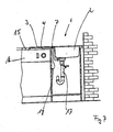
- Fig. 7 is a possible installation situation shown.
- the sink 1 according to the invention is inserted into an unspecified installation opening of a worktop 15.
- the area of the storage area 3 partly surmounted by another kitchen appliance, in the present case a dishwasher 16.
- the heating device 4 including the heating element 5 and the connection 7 remain within the thickness of the work surface 15, ie not projecting downwards, so that the Dishwasher 16 is not hindered by this.
- Below the sink 2 are drain pipes 17.
- an electrical supply cable 18 is connected, which is connected at the end to a power connection, not shown.
Landscapes
- Engineering & Computer Science (AREA)
- Life Sciences & Earth Sciences (AREA)
- Environmental & Geological Engineering (AREA)
- Health & Medical Sciences (AREA)
- Hydrology & Water Resources (AREA)
- Public Health (AREA)
- Water Supply & Treatment (AREA)
- Sustainable Development (AREA)
- Resistance Heating (AREA)
- Table Devices Or Equipment (AREA)
- Devices For Warming Or Keeping Food Or Tableware Hot (AREA)
Claims (9)
- Évier (1) avec au moins une cuvette d'évier (2) et au moins une surface de plaque (3) pour son utilisation dans les cuisines, dans lequel est prévue une unité chauffante (4) pour chauffer la surface de plaque (3) et dans lequel l'unité chauffante (4) est prévue sous la surface de plaque (3), dans lequel au moins un élément chauffant (5) configuré en guise d'élément chauffant à résistance de l'unité chauffante (4) est fixé sur le côté inférieur de la surface de plaque (3), de manière que la surface de plaque (3) peut être utilisée comme une zone de rétention de chaleur (11) pour la vaisselle et les repas, caractérisé en ce que l'élément chauffant (5) est configuré comme un conducteur chauffant à résistance plate et est imprimé sur le côté inférieur de la surface de plaque (3) composé de verre.
- Évier selon la revendication 1, caractérisé en ce que l'on fournit le connecteur électrique inférieur (7) pour l'unité chauffante (4).
- Évier selon la revendication 1 ou 2, caractérisé en ce que l'élément chauffant (5) est configuré comme un élément chauffant à résistance configuré sous forme de boucle de méandre ou comme un élément chauffant de surface à résistance.
- Évier selon l'une des revendications précédentes, caractérisé en ce que lorsque la surface de plaque (3) est composé de verre l'élément chauffant (5) est directement imprimé sur le côté inférieur (6) de la surface de plaque (3), sur le côté inférieur (6) imprimé avec l'élément chauffant (5) est prévu une couche de peinture (13), en particulier une couche de peinture décorative, et la couche en composite est cuite.
- Évier selon l'une des revendications précédentes 1 à 3, caractérisé en ce que lorsque la surface de plaque (3) est composé de verre, une couche de peinture (13) de préférence cuite en particulier une couche de peinture décorative, est directement prévue sur le côté inférieur (6), l'élément chauffant (5) est imprimée sur la couche de peinture (13) et la couche en composite est cuite.
- Évier selon l'une des revendications précédentes, caractérisé en ce qu'un couvercle (12) pour l'élément chauffant (5) et/ou un câble d'alimentation électrique (7) est pourvu sur la partie inférieure.
- Évier selon la revendication 6, caractérisé en ce que le couvercle (12) a un revêtement de scellement appliqué sur l'élément chauffant (5).
- Évier selon l'une des revendications précédentes, caractérisé en ce que l'on fournit des moyens de commande manuels (14), en particulier des capteurs, des boutons poussoirs, des commandes rotatives ou à glissière, pour régler l'unité chauffante (4).
- Évier selon l'une des revendications précédentes, caractérisé en ce que la puissance de chauffe de l'unité chauffante peut être ajustée dans des étapes prédéterminées, en particulier dans une plage de température allant de 20°C à 120°C.
Applications Claiming Priority (2)
| Application Number | Priority Date | Filing Date | Title |
|---|---|---|---|
| DE102007061158 | 2007-12-17 | ||
| DE102008003745A DE102008003745C5 (de) | 2007-12-17 | 2008-01-10 | Spüle |
Publications (3)
| Publication Number | Publication Date |
|---|---|
| EP2072694A2 EP2072694A2 (fr) | 2009-06-24 |
| EP2072694A3 EP2072694A3 (fr) | 2014-05-14 |
| EP2072694B1 true EP2072694B1 (fr) | 2016-11-02 |
Family
ID=40416949
Family Applications (1)
| Application Number | Title | Priority Date | Filing Date |
|---|---|---|---|
| EP08021716.9A Not-in-force EP2072694B1 (fr) | 2007-12-17 | 2008-12-15 | Evier |
Country Status (1)
| Country | Link |
|---|---|
| EP (1) | EP2072694B1 (fr) |
Families Citing this family (1)
| Publication number | Priority date | Publication date | Assignee | Title |
|---|---|---|---|---|
| RU2495613C1 (ru) * | 2012-04-19 | 2013-10-20 | Денис Вадимович Бирюков | Способ изготовления раковин из минерального материала на основе акрила и акриловая раковина |
Family Cites Families (4)
| Publication number | Priority date | Publication date | Assignee | Title |
|---|---|---|---|---|
| DE1895766U (de) * | 1964-04-15 | 1964-07-02 | Caspar & Co | Als saeuglingspflegekombination ausgebildete vorrichtung. |
| DE2610893A1 (de) * | 1976-03-16 | 1977-09-29 | Edeltraud Schneider | Beheizte ablageflaechen an spuelen |
| DE29616038U1 (de) * | 1996-09-14 | 1996-11-07 | Wellmann Gustav Gmbh & Co Kg | Vorrichtung in Arbeitsräumen |
| DE20119844U1 (de) * | 2001-12-07 | 2002-04-25 | Schock Hans Peter | Multifunktionsspüle |
-
2008
- 2008-12-15 EP EP08021716.9A patent/EP2072694B1/fr not_active Not-in-force
Also Published As
| Publication number | Publication date |
|---|---|
| EP2072694A2 (fr) | 2009-06-24 |
| EP2072694A3 (fr) | 2014-05-14 |
Similar Documents
| Publication | Publication Date | Title |
|---|---|---|
| EP3190937B1 (fr) | Rehausse de cuisson pour un récipient chauffant d'un robot ménager | |
| EP2295869B1 (fr) | Dispositif pour une enceinte de cuisson doté d'un élément de chauffage à couche épaisse | |
| EP0234373A2 (fr) | Unité de cuisson avec élément chauffant radiant | |
| DE102008038783A1 (de) | Küchenmaschine mit einem Rührgefäß sowie Verfahren hierzu | |
| DE19729661A1 (de) | Erwärmungssystem | |
| EP2633239B1 (fr) | Support de récipient et plaque de cuisson au gaz | |
| EP2072694B1 (fr) | Evier | |
| EP3598848B1 (fr) | Dispositif de chauffage pour une table de cuisson et table de cuisson | |
| DE202015105700U1 (de) | Vielzweckerhitzer | |
| DE19811848B4 (de) | Elektrisches Koch- und Grillgerät | |
| EP3250002B1 (fr) | Appareil de cuisson ménager | |
| DE102008003745C5 (de) | Spüle | |
| DE10031167C2 (de) | Anordnung zum Garen von Speisen | |
| DE102004059822A1 (de) | Sensorvorrichtung für ein Kochfeld, Verfahren zum Betrieb einer Sensorvorrichtung und Verwendung eines Temperatursensors als Topferkennungssensor | |
| EP0607555B1 (fr) | Dispositif de nettoyage d'un four de cuisson | |
| EP3210508B1 (fr) | Gril électrique | |
| EP2896889B1 (fr) | Procédé destiné au fonctionnement d'un appareil de cuisson avec une plaque de cuisson et appareil de cuisson | |
| DE10204214B4 (de) | Warmhalteplatte | |
| DE19505801C2 (de) | Herdmulde mit einem Kochfeld, dem ein Auflageelement zum Auflegen von Grill- oder Bratgut zugeordnet ist | |
| EP0938859B1 (fr) | Système pour tenir chaud de la nourriture arrangée sur des plateaux | |
| DE1404843A1 (de) | Vorrichtung zum Einbau von Herden unter Arbeitsplatten | |
| DE3928620A1 (de) | Kochherd mit steuerung der energiezufuhr | |
| DE102008008143B4 (de) | Grillvorrichtung | |
| WO2003037149A1 (fr) | Appareil de cuisson universel portatif | |
| EP3250001B1 (fr) | Appareil de cuisson ménager |
Legal Events
| Date | Code | Title | Description |
|---|---|---|---|
| PUAI | Public reference made under article 153(3) epc to a published international application that has entered the european phase |
Free format text: ORIGINAL CODE: 0009012 |
|
| AK | Designated contracting states |
Kind code of ref document: A2 Designated state(s): AT BE BG CH CY CZ DE DK EE ES FI FR GB GR HR HU IE IS IT LI LT LU LV MC MT NL NO PL PT RO SE SI SK TR |
|
| AX | Request for extension of the european patent |
Extension state: AL BA MK RS |
|
| RAP1 | Party data changed (applicant data changed or rights of an application transferred) |
Owner name: TEKA INDUSTRIAL S.A. |
|
| PUAL | Search report despatched |
Free format text: ORIGINAL CODE: 0009013 |
|
| AK | Designated contracting states |
Kind code of ref document: A3 Designated state(s): AT BE BG CH CY CZ DE DK EE ES FI FR GB GR HR HU IE IS IT LI LT LU LV MC MT NL NO PL PT RO SE SI SK TR |
|
| AX | Request for extension of the european patent |
Extension state: AL BA MK RS |
|
| RIC1 | Information provided on ipc code assigned before grant |
Ipc: A47B 77/04 20060101ALI20140407BHEP Ipc: E03C 1/18 20060101AFI20140407BHEP |
|
| 17P | Request for examination filed |
Effective date: 20141114 |
|
| RBV | Designated contracting states (corrected) |
Designated state(s): AT BE BG CH CY CZ DE DK EE ES FI FR GB GR HR HU IE IS IT LI LT LU LV MC MT NL NO PL PT RO SE SI SK TR |
|
| AKX | Designation fees paid |
Designated state(s): AT BE BG CH CY CZ DE DK EE ES FI FR GB GR HR HU IE IS IT LI LT LU LV MC MT NL NO PL PT RO SE SI SK TR |
|
| AXX | Extension fees paid |
Extension state: BA Extension state: AL Extension state: MK Extension state: RS |
|
| 17Q | First examination report despatched |
Effective date: 20151216 |
|
| GRAP | Despatch of communication of intention to grant a patent |
Free format text: ORIGINAL CODE: EPIDOSNIGR1 |
|
| INTG | Intention to grant announced |
Effective date: 20160511 |
|
| GRAS | Grant fee paid |
Free format text: ORIGINAL CODE: EPIDOSNIGR3 |
|
| GRAA | (expected) grant |
Free format text: ORIGINAL CODE: 0009210 |
|
| AK | Designated contracting states |
Kind code of ref document: B1 Designated state(s): AT BE BG CH CY CZ DE DK EE ES FI FR GB GR HR HU IE IS IT LI LT LU LV MC MT NL NO PL PT RO SE SI SK TR |
|
| REG | Reference to a national code |
Ref country code: GB Ref legal event code: FG4D Free format text: NOT ENGLISH |
|
| REG | Reference to a national code |
Ref country code: AT Ref legal event code: REF Ref document number: 842008 Country of ref document: AT Kind code of ref document: T Effective date: 20161115 Ref country code: CH Ref legal event code: EP |
|
| REG | Reference to a national code |
Ref country code: IE Ref legal event code: FG4D Free format text: LANGUAGE OF EP DOCUMENT: GERMAN |
|
| REG | Reference to a national code |
Ref country code: DE Ref legal event code: R096 Ref document number: 502008014750 Country of ref document: DE |
|
| PG25 | Lapsed in a contracting state [announced via postgrant information from national office to epo] |
Ref country code: LV Free format text: LAPSE BECAUSE OF FAILURE TO SUBMIT A TRANSLATION OF THE DESCRIPTION OR TO PAY THE FEE WITHIN THE PRESCRIBED TIME-LIMIT Effective date: 20161102 |
|
| REG | Reference to a national code |
Ref country code: NL Ref legal event code: MP Effective date: 20161102 |
|
| REG | Reference to a national code |
Ref country code: LT Ref legal event code: MG4D |
|
| PG25 | Lapsed in a contracting state [announced via postgrant information from national office to epo] |
Ref country code: NL Free format text: LAPSE BECAUSE OF FAILURE TO SUBMIT A TRANSLATION OF THE DESCRIPTION OR TO PAY THE FEE WITHIN THE PRESCRIBED TIME-LIMIT Effective date: 20161102 Ref country code: NO Free format text: LAPSE BECAUSE OF FAILURE TO SUBMIT A TRANSLATION OF THE DESCRIPTION OR TO PAY THE FEE WITHIN THE PRESCRIBED TIME-LIMIT Effective date: 20170202 Ref country code: GR Free format text: LAPSE BECAUSE OF FAILURE TO SUBMIT A TRANSLATION OF THE DESCRIPTION OR TO PAY THE FEE WITHIN THE PRESCRIBED TIME-LIMIT Effective date: 20170203 Ref country code: LT Free format text: LAPSE BECAUSE OF FAILURE TO SUBMIT A TRANSLATION OF THE DESCRIPTION OR TO PAY THE FEE WITHIN THE PRESCRIBED TIME-LIMIT Effective date: 20161102 Ref country code: SE Free format text: LAPSE BECAUSE OF FAILURE TO SUBMIT A TRANSLATION OF THE DESCRIPTION OR TO PAY THE FEE WITHIN THE PRESCRIBED TIME-LIMIT Effective date: 20161102 |
|
| PG25 | Lapsed in a contracting state [announced via postgrant information from national office to epo] |
Ref country code: ES Free format text: LAPSE BECAUSE OF FAILURE TO SUBMIT A TRANSLATION OF THE DESCRIPTION OR TO PAY THE FEE WITHIN THE PRESCRIBED TIME-LIMIT Effective date: 20161102 Ref country code: PL Free format text: LAPSE BECAUSE OF FAILURE TO SUBMIT A TRANSLATION OF THE DESCRIPTION OR TO PAY THE FEE WITHIN THE PRESCRIBED TIME-LIMIT Effective date: 20161102 Ref country code: PT Free format text: LAPSE BECAUSE OF FAILURE TO SUBMIT A TRANSLATION OF THE DESCRIPTION OR TO PAY THE FEE WITHIN THE PRESCRIBED TIME-LIMIT Effective date: 20170302 Ref country code: BE Free format text: LAPSE BECAUSE OF NON-PAYMENT OF DUE FEES Effective date: 20161231 Ref country code: IS Free format text: LAPSE BECAUSE OF FAILURE TO SUBMIT A TRANSLATION OF THE DESCRIPTION OR TO PAY THE FEE WITHIN THE PRESCRIBED TIME-LIMIT Effective date: 20170302 Ref country code: HR Free format text: LAPSE BECAUSE OF FAILURE TO SUBMIT A TRANSLATION OF THE DESCRIPTION OR TO PAY THE FEE WITHIN THE PRESCRIBED TIME-LIMIT Effective date: 20161102 Ref country code: FI Free format text: LAPSE BECAUSE OF FAILURE TO SUBMIT A TRANSLATION OF THE DESCRIPTION OR TO PAY THE FEE WITHIN THE PRESCRIBED TIME-LIMIT Effective date: 20161102 |
|
| REG | Reference to a national code |
Ref country code: DE Ref legal event code: R119 Ref document number: 502008014750 Country of ref document: DE |
|
| PG25 | Lapsed in a contracting state [announced via postgrant information from national office to epo] |
Ref country code: DK Free format text: LAPSE BECAUSE OF FAILURE TO SUBMIT A TRANSLATION OF THE DESCRIPTION OR TO PAY THE FEE WITHIN THE PRESCRIBED TIME-LIMIT Effective date: 20161102 Ref country code: CZ Free format text: LAPSE BECAUSE OF FAILURE TO SUBMIT A TRANSLATION OF THE DESCRIPTION OR TO PAY THE FEE WITHIN THE PRESCRIBED TIME-LIMIT Effective date: 20161102 Ref country code: EE Free format text: LAPSE BECAUSE OF FAILURE TO SUBMIT A TRANSLATION OF THE DESCRIPTION OR TO PAY THE FEE WITHIN THE PRESCRIBED TIME-LIMIT Effective date: 20161102 Ref country code: RO Free format text: LAPSE BECAUSE OF FAILURE TO SUBMIT A TRANSLATION OF THE DESCRIPTION OR TO PAY THE FEE WITHIN THE PRESCRIBED TIME-LIMIT Effective date: 20161102 Ref country code: SK Free format text: LAPSE BECAUSE OF FAILURE TO SUBMIT A TRANSLATION OF THE DESCRIPTION OR TO PAY THE FEE WITHIN THE PRESCRIBED TIME-LIMIT Effective date: 20161102 |
|
| REG | Reference to a national code |
Ref country code: CH Ref legal event code: PL |
|
| PG25 | Lapsed in a contracting state [announced via postgrant information from national office to epo] |
Ref country code: IT Free format text: LAPSE BECAUSE OF FAILURE TO SUBMIT A TRANSLATION OF THE DESCRIPTION OR TO PAY THE FEE WITHIN THE PRESCRIBED TIME-LIMIT Effective date: 20161102 Ref country code: BG Free format text: LAPSE BECAUSE OF FAILURE TO SUBMIT A TRANSLATION OF THE DESCRIPTION OR TO PAY THE FEE WITHIN THE PRESCRIBED TIME-LIMIT Effective date: 20170202 |
|
| PLBE | No opposition filed within time limit |
Free format text: ORIGINAL CODE: 0009261 |
|
| STAA | Information on the status of an ep patent application or granted ep patent |
Free format text: STATUS: NO OPPOSITION FILED WITHIN TIME LIMIT |
|
| PG25 | Lapsed in a contracting state [announced via postgrant information from national office to epo] |
Ref country code: MC Free format text: LAPSE BECAUSE OF FAILURE TO SUBMIT A TRANSLATION OF THE DESCRIPTION OR TO PAY THE FEE WITHIN THE PRESCRIBED TIME-LIMIT Effective date: 20161102 |
|
| REG | Reference to a national code |
Ref country code: FR Ref legal event code: ST Effective date: 20170831 |
|
| REG | Reference to a national code |
Ref country code: IE Ref legal event code: MM4A |
|
| 26N | No opposition filed |
Effective date: 20170803 |
|
| GBPC | Gb: european patent ceased through non-payment of renewal fee |
Effective date: 20170202 |
|
| PG25 | Lapsed in a contracting state [announced via postgrant information from national office to epo] |
Ref country code: LU Free format text: LAPSE BECAUSE OF NON-PAYMENT OF DUE FEES Effective date: 20161215 Ref country code: CH Free format text: LAPSE BECAUSE OF NON-PAYMENT OF DUE FEES Effective date: 20161231 Ref country code: FR Free format text: LAPSE BECAUSE OF NON-PAYMENT OF DUE FEES Effective date: 20170102 Ref country code: LI Free format text: LAPSE BECAUSE OF NON-PAYMENT OF DUE FEES Effective date: 20161231 |
|
| PG25 | Lapsed in a contracting state [announced via postgrant information from national office to epo] |
Ref country code: SI Free format text: LAPSE BECAUSE OF FAILURE TO SUBMIT A TRANSLATION OF THE DESCRIPTION OR TO PAY THE FEE WITHIN THE PRESCRIBED TIME-LIMIT Effective date: 20161102 Ref country code: IE Free format text: LAPSE BECAUSE OF NON-PAYMENT OF DUE FEES Effective date: 20161215 Ref country code: DE Free format text: LAPSE BECAUSE OF NON-PAYMENT OF DUE FEES Effective date: 20170701 |
|
| REG | Reference to a national code |
Ref country code: BE Ref legal event code: MM Effective date: 20161231 |
|
| REG | Reference to a national code |
Ref country code: AT Ref legal event code: MM01 Ref document number: 842008 Country of ref document: AT Kind code of ref document: T Effective date: 20161215 |
|
| PG25 | Lapsed in a contracting state [announced via postgrant information from national office to epo] |
Ref country code: GB Free format text: LAPSE BECAUSE OF NON-PAYMENT OF DUE FEES Effective date: 20170202 |
|
| PG25 | Lapsed in a contracting state [announced via postgrant information from national office to epo] |
Ref country code: HU Free format text: LAPSE BECAUSE OF FAILURE TO SUBMIT A TRANSLATION OF THE DESCRIPTION OR TO PAY THE FEE WITHIN THE PRESCRIBED TIME-LIMIT; INVALID AB INITIO Effective date: 20081215 Ref country code: CY Free format text: LAPSE BECAUSE OF FAILURE TO SUBMIT A TRANSLATION OF THE DESCRIPTION OR TO PAY THE FEE WITHIN THE PRESCRIBED TIME-LIMIT Effective date: 20161102 Ref country code: AT Free format text: LAPSE BECAUSE OF NON-PAYMENT OF DUE FEES Effective date: 20161215 |
|
| PG25 | Lapsed in a contracting state [announced via postgrant information from national office to epo] |
Ref country code: TR Free format text: LAPSE BECAUSE OF FAILURE TO SUBMIT A TRANSLATION OF THE DESCRIPTION OR TO PAY THE FEE WITHIN THE PRESCRIBED TIME-LIMIT Effective date: 20161102 |
|
| PG25 | Lapsed in a contracting state [announced via postgrant information from national office to epo] |
Ref country code: MT Free format text: LAPSE BECAUSE OF FAILURE TO SUBMIT A TRANSLATION OF THE DESCRIPTION OR TO PAY THE FEE WITHIN THE PRESCRIBED TIME-LIMIT Effective date: 20161102 |