EP2072694B1 - Sink - Google Patents
Sink Download PDFInfo
- Publication number
- EP2072694B1 EP2072694B1 EP08021716.9A EP08021716A EP2072694B1 EP 2072694 B1 EP2072694 B1 EP 2072694B1 EP 08021716 A EP08021716 A EP 08021716A EP 2072694 B1 EP2072694 B1 EP 2072694B1
- Authority
- EP
- European Patent Office
- Prior art keywords
- heating element
- sink
- heating
- tray surface
- sink according
- Prior art date
- Legal status (The legal status is an assumption and is not a legal conclusion. Google has not performed a legal analysis and makes no representation as to the accuracy of the status listed.)
- Not-in-force
Links
Images


Classifications
-
- E—FIXED CONSTRUCTIONS
- E03—WATER SUPPLY; SEWERAGE
- E03C—DOMESTIC PLUMBING INSTALLATIONS FOR FRESH WATER OR WASTE WATER; SINKS
- E03C1/00—Domestic plumbing installations for fresh water or waste water; Sinks
- E03C1/12—Plumbing installations for waste water; Basins or fountains connected thereto; Sinks
- E03C1/18—Sinks, whether or not connected to the waste-pipe
-
- A—HUMAN NECESSITIES
- A47—FURNITURE; DOMESTIC ARTICLES OR APPLIANCES; COFFEE MILLS; SPICE MILLS; SUCTION CLEANERS IN GENERAL
- A47B—TABLES; DESKS; OFFICE FURNITURE; CABINETS; DRAWERS; GENERAL DETAILS OF FURNITURE
- A47B77/00—Kitchen cabinets
- A47B77/04—Provision for particular uses of compartments or other parts ; Compartments moving up and down, revolving parts
- A47B77/08—Provision for particular uses of compartments or other parts ; Compartments moving up and down, revolving parts for incorporating apparatus operated by power, including water power; for incorporating apparatus for cooking, cooling, or laundry purposes
Definitions
- the invention relates to a sink with the preamble features of claim 1.
- a generic sink is already out of the DE 26 10 893 A1 known.
- heating is mounted under the shelf of the sink.
- the heated shelf can be used as a hot plate for food or as a dry plate for dishes and other parts.
- the DE 296 16 038 U1 discloses a device in household kitchens having a worktop, wherein on a lower side of the worktop, a heating device may be provided so that the worktop can perform the function of a hot plate.
- the heating device may be a powered by electricity, gas or other heat medium radiator.
- the worktop may have a cavity into which a radiator is inserted.
- Object of the present invention is to provide a sink of the aforementioned type, in which there is a good heat transfer from the heating element to the shelf and at the same time a good attachment of the heating element.
- a heating device for heating the storage area is provided for this purpose, so that the storage area can be used as a holding temperature range.
- the invention considerably extends the field of application of a sink.
- the storage space can thus be used not only for parking used or washed dishes, but at the same time as a warming surface for cups, plates, plates and other dishes, preferably made of ceramics, as well as prepared food and the like.
- the storage space of the sink has a double function.
- the heating element is designed as a preferably elongated flat keepssflowerleiter, ultimately thus represents a mixed form between the heating wire and committeenheizelement, this element is then printed on the underside of the shelf. This results in a simple planar contact of the heating element to the underside of the storage area and thus a good heat transfer and at the same time a simple attachment of the heating element.
- the storage surface made of glass.
- the sink in the case of a storage area consisting of glass, the sink as a whole usually consists of different components.
- a sink preferably made of stainless steel, attached, in particular glued under.
- the storage area of the sink if it is used as a warming surface, is needed before meals and then on the shelf then usually no used dishes. After meals, when it is no longer necessary to keep warm, the same area is then used in its original function, namely as a storage area. Usually overlap from the time schedule in the kitchen, the processes "keeping warm before meals” and “shutdown or rinse off after meals” not.
- the inventive design has the advantage that the holding surface also facilitates the Abspolvorgang when washed dishes is placed on a slightly heated storage area and results in a faster drying of the dishes due to the heated storage area.
- the heater is provided below the shelf, so that the space above the shelf for free use is available and the handling of the user is not limited.
- the arrangement of the heater below the shelf and an accidental contact with the heater is excluded by the operator.
- the sink with the heater is a structural unit that can be manufactured as such and also installed.
- the heating device is electrically operated, wherein it is appropriate to provide a lower-side electrical connection for the heating device. In this way, the electrical connection remains invisible from the outside.
- the heating element is designed so that the heat which can be emitted during operation does not exceed a predetermined limit value.
- the heating element is arranged as a surface heating element or as a particular loop-shaped Resistance heating conductor formed whose material, length and / or diameter are adapted to the limit for the maximum heat releasable. A corresponding adjustment is also present in the case of the surface heating element.
- the heater in the installed state of the sink does not survive on the underside of the thickness of the worktop.
- the heating element remains within the worktop thickness, in particular including the connection, no undermined dishwashers, drawers or the like are hindered.
- the storage area is at least partially flat.
- the predominant area, in particular more than 70% of the storage area should be flat on the upper side. In this way, a good surface heat transfer when using the storage area as a warming surface on the parts to be heated, which are located on the shelf, be guaranteed.
- the heating element can be printed directly on the underside of the storage area. Subsequently, a decorative paint is applied. Then the unit is burned. In this variant, the heating element is visible from above through the storage area, which makes it easier for the user to recognize the heated area and to arrange the material to be heated thereon.
- at least one color layer is first applied to the underside of the storage surface and then baked. It is understood that it is also possible to print different colors / layers to highlight the area of the holding surface. Subsequently, the heating element is printed on the baked ink layer and a re-bake process is performed. The heating spiral is not visible from above. In particular, in the latter embodiment, it makes sense to provide on the top of the shelf marks, especially in the form of imprints or centering for indicating the location of the lower-side heating element and the arrangement of the material to be heated.
- a liquid-protective cover for the heating element and / or the electrical connection is provided on the underside.
- the cover it is preferable for the cover to be a sealing coating applied to the heating layer.
- the coating can also be designed as thermal insulation, which has the advantage that parts located under the heating device, such as objects located in drawers for example, are not affected.
- control the heater manually controllable control means are provided by the operator. Although it is in principle possible to provide these control means also away from or away from the sink, it is in view of the fact that the sink is a uniformly manageable component, to arrange the control means at the top of the sink.
- the control means may be any means for actuating the heater, in particular sensors, pushbuttons and rotary or slide control.
- control means it is possible to design the control means as a simple on / off switch, wherein the heater then has only one possible heat level. It is preferred, however, if the heating power of the heating device via the control means in predetermined levels or is infinitely adjustable.
- the heating power should be adjustable so that a temperature between 20 ° C and 120 °, in particular between 30 ° C and 90 ° C is adjustable. It is understood that the heater is to be formed according to the material used in the storage area accordingly.
- the sink In order not to inadvertently penetrate moisture from the top of the sink through the sink body, the sink is sealed in particular in the region of any openings for the control means.
- the sinks 1 each have at least one sink 2 and at least one storage area 3.
- Rinse 1 may in principle also have two sinks 2 and / or two shelves and rest basin or the like.
- the sink 1 is assigned a heater 4, which serves to heat the shelf 3, so that the storage area 3 can also be used as a warming area and thus fulfills a dual function.
- the heater 4 which has at least one heating element 5, attached to the bottom 6 of the storage area 3, wherein the heating of the storage area 3 and the Guts to be heated at least substantially by heat conduction.
- the heater 4 is electrically operated in the present case and has for this purpose a lower-side electrical connection 7, which may be a plug, a plug receptacle or another electrical connection element.
- the heating element 5 is in the present case designed so that the deliverable amount of heat can not exceed a predetermined limit or a predetermined temperature, even without thermostats or other temperature monitoring units are provided. This is ultimately an intrinsically safe heating element 5.
- the heating element 5 is mounted in meander loops on the bottom 6 of the storage area 3.
- the heating element 5 is an elongate flat resistance heating conductor which has the cross-sectional shape of an elongated rectangle.
- the flatticiansSchleiters basically a flat, such as rectangular or roundinstitunheizelement that covers a large part of the bottom 6 of the shelf 3, can also be used as a horrsflowerdraht, then also be provided a larger number of meander loops can.
- the flat horrsflowerleiter is printed on the bottom 6 of the shelf 3.
- the storage surface 3 of the sink 1 made of glass. It is then understood that the storage area 3 is formed by a glass plate, which makes up the entire upper part of the sink 1. In the area of the sink 3 is a breakthrough 8, under which the sink 2 is mounted, in particular under-glued. In the illustrated embodiment with a glass shelf, a 10 mm thick safety glass is provided, the minimum thickness should be 6 mm.
- the sink 1 made of stainless steel, wherein the sink 2 is deep-drawn. It is understood that this principle can also be welded to the sink body.
- the top 9 of the shelf 3 is flat, while in the in Fig. 3 illustrated embodiment, two mutually parallel stages 10 are provided.
- the heating element 5 is in this embodiment only in the lying between the two stages 10 area, which thus forms a holding portion 11.
- the region lying outside the steps can also be provided on each side with a heating element, so that these areas can also constitute holding regions.
- the heating element 5 is applied directly to the bottom 6 of the storage area 3. Below the heating element 5 is a sealing coating as a cover 12. In the in Fig. 5 illustrated embodiment is located directly on the bottom 6 a baked ink layer 13. Below the ink layer 13 is the heating element 5, which in turn is covered by the cover 12 downwards. In the embodiment according to Fig. 6 the heating element 5 is in turn attached directly to the underside 6 of the storage surface 3, wherein the heating element 5 and not covered by the heating element 5 areas of the bottom 6 are covered by an overlying paint layer 13. The conclusion towards the bottom forms the ultimately intended for corrosion protection cover 12th
- control means 14 are provided for controlling the heating device 4 .
- the arrangement of the control means 14 on the sink 1 is arbitrary. At the in Fig. 1 illustrated embodiment, the control means 14 are close to the sink 2, while in the in Fig. 3 illustrated embodiment, the control means 14 are provided at the edge of the sink 1 remote from the sink 2. Consists the upper rinsing body made of glass, as in the embodiment according to FIG Fig. 1 is provided, it is in the control means 14 is preferably a sensor (touch control), while in the in Fig. 3 illustrated embodiment with the existing metal storage area 3, a sliding or rotary control is provided.
- the heating device 4 is not only switched on and off, but also adjustable, so that there is a Temperaturinstell Scheme between a minimum of 20 ° C and a maximum of 120 ° C. It is understood that all lying within the aforementioned interval intervals and ranges are basically possible, for example 30 ° C to 100 ° C, 30 ° C to 80 ° C or 30 ° C to 70 ° C.
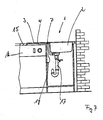
- Fig. 7 is a possible installation situation shown.
- the sink 1 according to the invention is inserted into an unspecified installation opening of a worktop 15.
- the area of the storage area 3 partly surmounted by another kitchen appliance, in the present case a dishwasher 16.
- the heating device 4 including the heating element 5 and the connection 7 remain within the thickness of the work surface 15, ie not projecting downwards, so that the Dishwasher 16 is not hindered by this.
- Below the sink 2 are drain pipes 17.
- an electrical supply cable 18 is connected, which is connected at the end to a power connection, not shown.
Landscapes
- Engineering & Computer Science (AREA)
- Life Sciences & Earth Sciences (AREA)
- Environmental & Geological Engineering (AREA)
- Health & Medical Sciences (AREA)
- Hydrology & Water Resources (AREA)
- Public Health (AREA)
- Water Supply & Treatment (AREA)
- Sustainable Development (AREA)
- Resistance Heating (AREA)
- Table Devices Or Equipment (AREA)
- Devices For Warming Or Keeping Food Or Tableware Hot (AREA)
Description
Die Erfindung betrifft eine Spüle mit den Oberbegriffsmerkmalen von Anspruch 1.The invention relates to a sink with the preamble features of claim 1.
Eine gattungsgemäße Spüle ist bereits aus der
Aus der
Die
Aufgabe der vorliegenden Erfindung ist es, eine Spüle der eingangs genannten Art zur Verfügung zu stellen, bei der sich eine gute Wärmeübertragung vom Heizelement auf die Abstellfläche und gleichzeitig eine gute Befestigung des Heizelements ergibt.Object of the present invention is to provide a sink of the aforementioned type, in which there is a good heat transfer from the heating element to the shelf and at the same time a good attachment of the heating element.
Die vorgenannte Aufgabe wird durch eine Spüle mit den Merkmalen von Anspruch 1 gelöst.The above object is achieved by a sink with the features of claim 1.
Erfindungsgemäß ist zu diesem Zweck eine Heizeinrichtung zur Beheizung der Abstellfläche vorgesehen, so dass die Abstellfläche als Warmhaltebereich nutzbar ist. Durch die Erfindung wird der Einsatzbereich einer Spüle erheblich erweitert. Die Abstellfläche kann damit nicht nur zum Abstellen von gebrauchtem oder gespültem Geschirr verwendet werden, sondern gleichzeitig als Warmhaltefläche für Tassen, Teller, Platten und sonstiges Geschirr, vorzugsweise aus Keramik, sowie zubereitete Speisen und dergleichen. Durch die Erfindung hat die Abstellfläche der Spüle eine Doppelfunktion.According to the invention, a heating device for heating the storage area is provided for this purpose, so that the storage area can be used as a holding temperature range. The invention considerably extends the field of application of a sink. The storage space can thus be used not only for parking used or washed dishes, but at the same time as a warming surface for cups, plates, plates and other dishes, preferably made of ceramics, as well as prepared food and the like. By the invention, the storage space of the sink has a double function.
Vorgesehen ist in diesem Zusammenhang, dass das Heizelement als vorzugsweise langgestreckter flacher Widerstandsheizleiter ausgebildet ist, letztlich damit eine Mischform zwischen Heizdraht und Flächenheizelement darstellt, wobei dieses Element dann auf die Unterseite der Abstellfläche aufgedruckt ist. Hierdurch ergibt sich dann eine einfache flächige Anlage des Heizelements an die Unterseite der Abstellfläche und damit eine gute Wärmeübertragung und gleichzeitig eine einfache Befestigung des Heizelements.It is provided in this context that the heating element is designed as a preferably elongated flat Widerstandsheizleiter, ultimately thus represents a mixed form between the heating wire and Flächenheizelement, this element is then printed on the underside of the shelf. This results in a simple planar contact of the heating element to the underside of the storage area and thus a good heat transfer and at the same time a simple attachment of the heating element.
Erfindungsgemäß besteht die Abstellfläche aus Glas. Bei einer aus Glas bestehenden Abstellfläche besteht die Spüle insgesamt üblicherweise aus unterschiedlichen Komponenten. So kann die Oberseite bzw. der obere Spülenkörper der Spüle aus Glas, insbesondere Sicherheitsglas bestehen, wobei im Bereich des Spülbeckens ein Durchbruch vorgesehen ist. Unter diesem Durchbruch ist dann ein Spülbecken, vorzugsweise aus Edelstahl, angebracht, insbesondere untergeklebt.According to the invention, the storage surface made of glass. In the case of a storage area consisting of glass, the sink as a whole usually consists of different components. Thus, the upper side or the upper sink body of the sink made of glass, in particular safety glass, wherein an opening is provided in the region of the sink. Under this breakthrough then a sink, preferably made of stainless steel, attached, in particular glued under.
Damit kann auf an sich aus dem Stand der Technik bekannte, elektrisch beheizte Warmhaltegeräte verzichtet werden, die entweder fest in Küchenarbeitsplatten eingebaut sind oder als Einzelgeräte im Küchenbereich abgestellt sind. Bei den bekannten Warmhaltegeräten handelt es sich um separate Baueinheiten, die nicht nur vergleichsweise teuer sind, sondern auch einen nicht unerheblichen Platzbedarf haben. Durch die Erfindung wird es letztlich möglich, auch bei kleineren Küchen, die kein hinreichendes Raumangebot für ein separates Warmhaltegerät haben, die Warmhaltefunktion zu realisieren, nämlich durch die Abstellfläche der erfindungsgemäßen Spüle, die ohnehin notwendig ist.This can be dispensed with known from the prior art, electrically heated holding devices that are either permanently installed in kitchen countertops or are turned off as individual appliances in the kitchen area. In the known warming devices are separate units that are not only relatively expensive, but also have a significant amount of space. By the invention, it is ultimately possible, even with smaller kitchens, which have no sufficient space for a separate heater, to realize the warming function, namely by the footprint of the sink according to the invention, which is necessary anyway.
Letztlich ist im Zusammenhang mit der vorliegenden Erfindung erkannt worden, dass die Abstellfläche der Spüle, wenn sie als Warmhaltefläche genutzt wird, vor den Mahlzeiten benötigt wird und sich auf der Abstellfläche dann in der Regel kein gebrauchtes Geschirr befindet. Nach den Mahlzeiten, wenn ein Warmhalten nicht mehr erforderlich ist, wird die gleiche Fläche dann in ihrer ursprünglichen Funktion, nämlich als Abstellfläche benutzt. In der Regel überschneiden sich vom zeitlichen Ablauf in der Küche her die Vorgänge "Warmhalten vor den Mahlzeiten" und "Abstellen bzw. Abspülen nach den Mahlzeiten" nicht.Ultimately, it has been recognized in the context of the present invention that the storage area of the sink, if it is used as a warming surface, is needed before meals and then on the shelf then usually no used dishes. After meals, when it is no longer necessary to keep warm, the same area is then used in its original function, namely as a storage area. Usually overlap from the time schedule in the kitchen, the processes "keeping warm before meals" and "shutdown or rinse off after meals" not.
Schließlich hat die erfindungsgemäße Ausgestaltung den Vorteil, dass die Warmhaltefläche auch den Abspolvorgang erleichtert, wenn gespültes Geschirr auf einer leicht erwärmten Abstellfläche abgestellt wird und sich aufgrund der beheizten Abstellfläche ein schnelleres Abtrocknen des Geschirrs ergibt.Finally, the inventive design has the advantage that the holding surface also facilitates the Abspolvorgang when washed dishes is placed on a slightly heated storage area and results in a faster drying of the dishes due to the heated storage area.
Die Heizeinrichtung ist unterhalb der Abstellfläche vorgesehen, so dass der Raum oberhalb der Abstellfläche zur freien Nutzung zur Verfügung steht und die Handhabungsfreiheit des Nutzers nicht eingeschränkt ist. Durch die Anordnung der Heizeinrichtung unterhalb der Abstellfläche ist auch ein unbeabsichtigtes Berühren der Heizeinrichtung durch die Bedienungsperson ausgeschlossen.The heater is provided below the shelf, so that the space above the shelf for free use is available and the handling of the user is not limited. The arrangement of the heater below the shelf and an accidental contact with the heater is excluded by the operator.
Zur einfachen Herstellung und Montage der erfindungsgemäßen Spüle bietet es sich an, dass wenigstens ein Heizelement der Heizeinrichtung an der Unterseite der Abstellfläche befestigt ist, wobei das Beheizen der Abstellfläche durch Wärmeleitung erfolgt. Damit stellt die Spüle mit der Heizeinrichtung eine Baueinheit dar, die als solche hergestellt und auch eingebaut werden kann.For ease of manufacture and assembly of the sink according to the invention, it is advisable that at least one heating element of the heater is fixed to the underside of the shelf, wherein the heating of the shelf is carried out by heat conduction. Thus, the sink with the heater is a structural unit that can be manufactured as such and also installed.
Erfindungsgemäß wird die Heizeinrichtung elektrisch betrieben, wobei es sich hierbei anbietet, einen unterseitigen elektrischen Anschluß für die Heizeinrichtung vorzusehen. Auf diese Weise bleibt der elektrische Anschluß von außen unsichtbar.According to the invention, the heating device is electrically operated, wherein it is appropriate to provide a lower-side electrical connection for the heating device. In this way, the electrical connection remains invisible from the outside.
Von besonderem Vorteil ist es, dass das Heizelement so ausgelegt ist, dass die bei Betrieb abgebbare Wärme einen vorgegebenen Grenzwert nicht überschreitet. Durch eine derartige eigengesicherte Heizeinrichtung kann auf Thermostate oder andere Temperaturüberwachungseinheiten ganz verzichtet werden und sowohl die Störanfälligkeit wie auch die Herstellungskosten können hierdurch reduziert werden. Im übrigen kann durch die eigengesicherte Heizeinrichtung ohne aufwendige Sicherungsmaßnahmen eine Überhitzung der Abstellfläche in jedem Fall verhindert werden.It is particularly advantageous that the heating element is designed so that the heat which can be emitted during operation does not exceed a predetermined limit value. By such an intrinsically safe heating device can be completely dispensed with thermostats or other temperature monitoring units and both the susceptibility and the production costs can be reduced thereby. Moreover, overheating of the storage area can be prevented in any case by the intrinsically safe heating without costly security measures.
Gemäß einer vorteilhaften Ausführungsform der vorliegenden Erfindung ist das Heizelement als Flächenheizelement oder als insbesondere schleifenförmig angeordneter Widerstandsheizleiter ausgebildet, dessen Material, Länge und/oder Durchmesser an den Grenzwert für die maximal abgebbare Wärme angepaßt sind. Eine entsprechende Anpassung liegt im übrigen auch bei dem Flächenheizelement vor.According to an advantageous embodiment of the present invention, the heating element is arranged as a surface heating element or as a particular loop-shaped Resistance heating conductor formed whose material, length and / or diameter are adapted to the limit for the maximum heat releasable. A corresponding adjustment is also present in the case of the surface heating element.
Mit der vorgenannten Eigensicherheit durch Widerstandsheizelemente kann auf einfache Weise eine elektrisch beheizbare Abstellfläche geschaffen werden, die es ermöglichen, dass eine maximale Systemtemperatur auch ohne weitere Regelorgane, wie Thermostate, nicht überschritten wird. Positiv bei dieser Lösung ist auch, dass das System insgesamt eine geringe elektrische Leistung benötigt.With the aforementioned intrinsic safety by resistance heating elements can be easily created an electrically heated storage area, which make it possible that a maximum system temperature without other control elements, such as thermostats, is not exceeded. Another positive aspect of this solution is that the system as a whole requires low electrical power.
Im übrigen ist es von besonderem Vorteil, dass die Heizeinrichtung im eingebauten Zustand der Spüle unterseitig nicht über die Dicke der Arbeitsplatte übersteht. Dadurch, dass das Heizelement insbesondere einschließlich des Anschlusses innerhalb der Arbeitsplattendicke verbleibt, werden hierdurch keine untergebauten Geschirrspüler, Schubladen oder dgl. behindert.Moreover, it is of particular advantage that the heater in the installed state of the sink does not survive on the underside of the thickness of the worktop. As a result of the fact that the heating element remains within the worktop thickness, in particular including the connection, no undermined dishwashers, drawers or the like are hindered.
Während es grundsätzlich möglich ist, auf der Abstellfläche Rillen oder erhabene Bereiche vorzusehen, bietet es sich bei der vorliegenden Erfindung an, wenn die Abstellfläche zumindest bereichsweise eben ist. Bevorzugt sollte die überwiegende Bereich, insbesondere mehr als 70% der Abstellfläche oberseitig eben sein. Hierdurch kann ein guter flächiger Wärmeübergang bei der Nutzung der Abstellfläche als Warmhaltefläche auf die zu erwärmenden Teile, die sich auf der Abstellfläche befinden, gewährleistet werden.While it is basically possible to provide grooves or raised areas on the storage area, it is useful in the present invention if the storage area is at least partially flat. Preferably, the predominant area, in particular more than 70% of the storage area, should be flat on the upper side. In this way, a good surface heat transfer when using the storage area as a warming surface on the parts to be heated, which are located on the shelf, be guaranteed.
Bei einer aus Glas bestehenden Abstellfläche bieten sich zwei Alternativen zur Anordnung des Heizelements an. Zum einen kann das Heizelement direkt auf die Unterseite der Abstellfläche gedruckt werden. Anschließend wird eine Dekorfarbe aufgebracht. Dann wird die Einheit eingebrannt. Bei dieser Variante ist das Heizelement von oben durch die Abstellfläche sichtbar, was es dem Nutzer erleichtert, die beheizte Fläche zu erkennen und das zu erwärmende Gut darauf anzuordnen. Bei der anderen Alternative wird auf die Unterseite der Abstellfläche zunächst wenigstens eine Farbschicht aufgebracht und diese dann eingebrannt. Es versteht sich, dass es auch möglich ist, verschiedene Farben/Schichten aufzudrucken, um den Bereich der Warmhaltefläche hervorzuheben. Anschließend wird auf die eingebrannte Farbschicht das Heizelement aufgedruckt und ein erneuter Einbrennvorgang wird durchgeführt. Hierbei ist die Heizspirale von oben nicht sichtbar. Insbesondere bei der letztgenannten Ausführungsform bietet es sich an, auf der Oberseite der Abstellfläche Markierungen, insbesondere in Form von Aufdrucken oder Zentrierelementen zur Anzeige des Ortes des unterseitigen Heizelementes und zur Anordnung des zu erwärmenden Gutes vorzusehen.In the case of a storage area consisting of glass, there are two alternatives for arranging the heating element. On the one hand, the heating element can be printed directly on the underside of the storage area. Subsequently, a decorative paint is applied. Then the unit is burned. In this variant, the heating element is visible from above through the storage area, which makes it easier for the user to recognize the heated area and to arrange the material to be heated thereon. In the other alternative, at least one color layer is first applied to the underside of the storage surface and then baked. It is understood that it is also possible to print different colors / layers to highlight the area of the holding surface. Subsequently, the heating element is printed on the baked ink layer and a re-bake process is performed. The heating spiral is not visible from above. In particular, in the latter embodiment, it makes sense to provide on the top of the shelf marks, especially in the form of imprints or centering for indicating the location of the lower-side heating element and the arrangement of the material to be heated.
Um insbesondere einen Korrosionsschutz durch eventuell von unten her, beispielsweise durch von einem Geschirrspüler eventuell aufsteigendem Wasserdampf, zu gewährleisten, ist unterseitig eine flüssigkeitsschützende Abdeckung für das Heizelement und/oder den elektrischen Anschluß vorgesehen. Bevorzugt ist es in diesem Zusammenhang, dass die Abdeckung eine auf die Heizschicht aufgebrachte, abdichtende Beschichtung ist. Gleichzeitig kann die Beschichtung auch als Wärmeisolierung ausgebildet sein, was den Vorteil hat, dass unter der Heizeinrichtung befindliche Teile, wie beispielsweise in Schubladen befindliche Gegenstände, nicht in Mitleidenschaft gezogen werden.In order to ensure in particular corrosion protection by possibly from below, for example, by a possibly rising from a dishwasher water vapor, a liquid-protective cover for the heating element and / or the electrical connection is provided on the underside. In this context, it is preferable for the cover to be a sealing coating applied to the heating layer. At the same time, the coating can also be designed as thermal insulation, which has the advantage that parts located under the heating device, such as objects located in drawers for example, are not affected.
Zur Ansteuerung der Heizeinrichtung sind von dem Bediener manuell betätigbare Steuermittel vorgesehen. Wenngleich es grundsätzlich möglich ist, diese Steuermittel auch abseits oder entfernt von der Spüle vorzusehen, bietet es sich im Hinblick darauf, dass die Spüle ein einheitllich handhabbares Bauteil ist, an, die Steuermittel an der Oberseite der Spüle anzuordnen.To control the heater manually controllable control means are provided by the operator. Although it is in principle possible to provide these control means also away from or away from the sink, it is in view of the fact that the sink is a uniformly manageable component, to arrange the control means at the top of the sink.
Bei den Steuermitteln kann es sich um jegliches Mittel zur Betätigung der Heizeinrichtung handeln, insbesondere um Sensoren, Drucktaster sowie Dreh- oder Schieberegler.The control means may be any means for actuating the heater, in particular sensors, pushbuttons and rotary or slide control.
Grundsätzlich ist es möglich, die Steuermittel als einfache Ein-/Aus-Schalter auszubilden, wobei die Heizeinrichtung dann nur eine mögliche Wärmstufe hat. Bevorzugt ist es aber, wenn die Heizleistung der Heizeinrichtung über die Steuermittel in vorgegebenen Stufen oder aber stufenlos einstellbar ist. Die Heizleistung sollte dabei derart einstellbar sein, dass eine Temperatur zwischen 20°C und 120°, insbesondere zwischen 30°C und 90°C einstellbar ist. Dabei versteht es sich, dass die Heizeinrichtung in Abhängigkeit des verwendeten Materials der Abstellfläche entsprechend auszubilden ist.In principle, it is possible to design the control means as a simple on / off switch, wherein the heater then has only one possible heat level. It is preferred, however, if the heating power of the heating device via the control means in predetermined levels or is infinitely adjustable. The heating power should be adjustable so that a temperature between 20 ° C and 120 °, in particular between 30 ° C and 90 ° C is adjustable. It is understood that the heater is to be formed according to the material used in the storage area accordingly.
Damit im übrigen von der Oberseite der Spüle her nicht unbeabsichtigt Feuchtigkeit durch den Spülenkörper dringt, ist die Spüle insbesondere im Bereich von etwaigen Durchbrechungen für die Steuermittel abgedichtet.In order not to inadvertently penetrate moisture from the top of the sink through the sink body, the sink is sealed in particular in the region of any openings for the control means.
Weitere Merkmale und Vorteile der vorliegenden Erfindung ergeben sich aus der nachfolgenden Beschreibung von Ausführungsbeispielen anhand der Zeichnung und der Zeichnung selbst. Dabei ist die Erfindung nicht auf die nachfolgend gezeigten und beschriebenen Ausführungsbeispiele beschränkt.Further features and advantages of the present invention will become apparent from the following description of exemplary embodiments with reference to the drawing and the drawing itself. The invention is not limited to the embodiments shown and described below.
Es zeigt
- Fig. 1
- eine Draufsicht auf eine erfindungsgemäße Spüle,
- Fig. 2
- eine Unteransicht der Spüle aus
Fig. 1 , - Fig. 3
- eine Draufsicht auf eine andere Ausführungsform einer erfindungsgemäßen Spüle,
- Fig. 4
- eine teilweise Schnittansicht der Abstellfläche einer erfindungsgemäßen Spüle,
- Fig. 5
- eine der
Fig. 4 entsprechende Ansicht einer anderen Ausführungsform einer erfindungsgemäßen Spüle, - Fig. 6
- eine der
Fig. 4 entsprechende Darstellung einer weiteren Ausführungsform einer erfindungsgemäßen Spüle und - Fig. 7
- eine Vorderansicht einer montierten Spüle im Einbauzustand.
- Fig. 1
- a top view of a sink according to the invention,
- Fig. 2
- a bottom view of the sink
Fig. 1 . - Fig. 3
- a top view of another embodiment of a sink according to the invention,
- Fig. 4
- a partial sectional view of the storage area of a sink according to the invention,
- Fig. 5
- one of the
Fig. 4 corresponding view of another embodiment of a sink according to the invention, - Fig. 6
- one of the
Fig. 4 corresponding representation of another embodiment of a sink according to the invention and - Fig. 7
- a front view of a mounted sink in the installed state.
In der Zeichnung sind verschiedene Spülen 1 dargestellt. Die Spülen 1 weisen dabei jeweils wenigstens ein Spülbecken 2 und wenigstens eine Abstellfläche 3 auf.In the drawing, various rinses 1 are shown. The sinks 1 each have at least one
Es versteht sich, dass die Erfindung nicht nur auf Ausführungsformen mit nur einem Spülbecken 2 und nur einer Abstellfläche 3 beschränkt sind. Spülen 1 können grundsätzlich auch zwei Spülbecken 2 und/oder zwei Abstellflächen sowie Restebecken oder dergleichen aufweisen.It is understood that the invention is not limited to embodiments with only one
Vorgesehen ist nun, dass der Spüle 1 eine Heizeinrichtung 4 zugeordnet ist, die zur Beheizung der Abstellfläche 3 dient, so dass die Abstellfläche 3 auch als Warmhaltebereich nutzbar ist und damit eine Doppelfunktion erfüllt. Wie sich aus einem Vergleich der
Wie sich aus
Bei der in den
Bei der in
In den
Zur Ansteuerung der Heizeinrichtung 4 sind Steuermittel 14 vorgesehen. Die Anordnung der Steuermittel 14 an der Spüle 1 ist beliebig. Bei der in
In
- 11
- Spülekitchen sink
- 22
- SpülbeckenSink
- 33
- Abstellflächeshelf
- 44
- Heizeinrichtungheater
- 55
- Heizelementheating element
- 66
- Unterseitebottom
- 77
- AnschlußConnection
- 88th
- Durchbruchbreakthrough
- 99
- Oberseitetop
- 1010
- Stufestep
- 1111
- WarmhaltebereichHolding area
- 1212
- Abdeckungcover
- 1313
- Farbschichtcoat of paint
- 1414
- Steuermittelcontrol means
- 1515
- Arbeitsplattecountertop
- 1616
- Spülmaschinedishwasher
- 1717
- Ablaufrohrdrain pipe
- 1818
- Zuleitungskabelpower cable
Claims (9)
- Sink (1) with at least one sink bowl (2) and at least one tray surface (3) for use thereof in kitchens, wherein a heating unit (4) is provided for heating the tray surface (3) and wherein the heating unit (4) is provided below the tray surface (3), wherein at least one heating element (5) configured as a resistance heating element of the heating unit (4) is fixed at the lower side of the tray surface (3), so that the tray surface (3) can be used as a heat-retaining area (11) for dishware and meals, characterized in that the heating element (5) is configured as a flat resistance heating conductor and is imprinted on the lower side of the tray surface (3) consisting of glass.
- Sink according to claim 1, characterized in that an underside electrical connector (7) for the heating unit (4) is provided.
- Sink according to claim 1 or 2, characterized in that the heating element (5) is configured as a resistance heating element configured in meander loop-shape or as a resistance surface heating element.
- Sink according to any of the preceding claims, characterized in that when the tray surface (3) consists of glass the heating element (5) is directly printed on the lower side (6) of the tray surface (3), on the lower side (6) printed with the heating element (5) there is provided a paint layer (13), in particular a decorative paint layer, and the layer composite is fired.
- Sink according to any of the preceding claims 1 to 3, characterized in that when the tray surface (3) consists of glass, there is directly provided a preferably fired paint layer (13), in particular decorative paint layer, on the lower side (6), the heating element (5) is imprinted on the paint layer (13) and the layer composite is fired.
- Sink according to any of the preceding claims, characterized in that a cover (12) for the heating element (5) and/or an electrical supply cable (7) is provided on the underside.
- Sink according to claim 6, characterized in that the cover (12) has a sealing coating applied on the heating element (5).
- Sink according to any of the preceding claims, characterized in that manual control means (14), in particular sensors, push buttons, rotary or slide controls, are provided for regulating the heating unit (4).
- Sink according to any of the preceding claims, characterized in that the heating power of the heating unit can be adjusted in predetermined steps, in particular in a temperature range between 20°C and 120°C.
Applications Claiming Priority (2)
| Application Number | Priority Date | Filing Date | Title |
|---|---|---|---|
| DE102007061158 | 2007-12-17 | ||
| DE102008003745A DE102008003745C5 (en) | 2007-12-17 | 2008-01-10 | kitchen sink |
Publications (3)
| Publication Number | Publication Date |
|---|---|
| EP2072694A2 EP2072694A2 (en) | 2009-06-24 |
| EP2072694A3 EP2072694A3 (en) | 2014-05-14 |
| EP2072694B1 true EP2072694B1 (en) | 2016-11-02 |
Family
ID=40416949
Family Applications (1)
| Application Number | Title | Priority Date | Filing Date |
|---|---|---|---|
| EP08021716.9A Not-in-force EP2072694B1 (en) | 2007-12-17 | 2008-12-15 | Sink |
Country Status (1)
| Country | Link |
|---|---|
| EP (1) | EP2072694B1 (en) |
Families Citing this family (1)
| Publication number | Priority date | Publication date | Assignee | Title |
|---|---|---|---|---|
| RU2495613C1 (en) * | 2012-04-19 | 2013-10-20 | Денис Вадимович Бирюков | Method of manufacturing sinks from mineral material based on acryl and acrylic sink |
Family Cites Families (4)
| Publication number | Priority date | Publication date | Assignee | Title |
|---|---|---|---|---|
| DE1895766U (en) * | 1964-04-15 | 1964-07-02 | Caspar & Co | DEVICE TRAINED AS AN INFANT CARE COMBINATION. |
| DE2610893A1 (en) * | 1976-03-16 | 1977-09-29 | Edeltraud Schneider | Electrically heated draining board for sinks - has heater on draining board underside enclosed by insulation |
| DE29616038U1 (en) * | 1996-09-14 | 1996-11-07 | Gustav Wellmann GmbH & Co. KG, 32130 Enger | Device in workrooms |
| DE20119844U1 (en) * | 2001-12-07 | 2002-04-25 | Schock, Hans-Peter, 73614 Schorndorf | Multifunction sink |
-
2008
- 2008-12-15 EP EP08021716.9A patent/EP2072694B1/en not_active Not-in-force
Also Published As
| Publication number | Publication date |
|---|---|
| EP2072694A2 (en) | 2009-06-24 |
| EP2072694A3 (en) | 2014-05-14 |
Similar Documents
| Publication | Publication Date | Title |
|---|---|---|
| EP3190937B1 (en) | Cooking attachment for a heatable vessel of a food processor | |
| EP2295869B1 (en) | Cooking chamber device with thick-film heating element | |
| EP0234373A2 (en) | Cooking unit with radiant heating element | |
| EP2431667A1 (en) | Insertable cooking tray with heating element and cooking device | |
| EP2633239B1 (en) | Pot support and gas cooking point | |
| EP2072694B1 (en) | Sink | |
| EP3250002B1 (en) | Domestic cooking device | |
| EP3598848B1 (en) | Cooking hob and heating device for a cooking hob | |
| DE202015105700U1 (en) | Vielzweckerhitzer | |
| DE19811848B4 (en) | Electric cooker and grill | |
| DE102008003745C5 (en) | kitchen sink | |
| DE10031167C2 (en) | Arrangement for cooking food | |
| DE102004059822A1 (en) | Sensor for a ceramic hob to determine hob temperature and the touching of cooking vessels has resistive and capacitive coupling functions | |
| EP0607555B1 (en) | Cleaning arrangement for a cooking oven | |
| EP3210508B1 (en) | Electric grill | |
| EP2896889B1 (en) | Method for operating a cooking device with a cooking hob and cooking device | |
| DE10204214B4 (en) | Hotplate | |
| DE19505801C2 (en) | Hob with a hob, which is assigned a support element for placing grilled or roasted food | |
| DE3928620A1 (en) | Electric cooking hob - has microprocessor control linked to temp. sensors for accurate regulation of actual cooking temp. | |
| DE102008008143B4 (en) | griller | |
| WO2003037149A1 (en) | Mobile universal cooking appliance | |
| EP3250001B1 (en) | Domestic cooking device | |
| DE1765832A1 (en) | Electric heater | |
| EP3771287A1 (en) | Radiation heating device and hob with such a radiation heating device | |
| EP0938859A1 (en) | Arrangement for keeping warm food which is arranged on plates |
Legal Events
| Date | Code | Title | Description |
|---|---|---|---|
| PUAI | Public reference made under article 153(3) epc to a published international application that has entered the european phase |
Free format text: ORIGINAL CODE: 0009012 |
|
| AK | Designated contracting states |
Kind code of ref document: A2 Designated state(s): AT BE BG CH CY CZ DE DK EE ES FI FR GB GR HR HU IE IS IT LI LT LU LV MC MT NL NO PL PT RO SE SI SK TR |
|
| AX | Request for extension of the european patent |
Extension state: AL BA MK RS |
|
| RAP1 | Party data changed (applicant data changed or rights of an application transferred) |
Owner name: TEKA INDUSTRIAL S.A. |
|
| PUAL | Search report despatched |
Free format text: ORIGINAL CODE: 0009013 |
|
| AK | Designated contracting states |
Kind code of ref document: A3 Designated state(s): AT BE BG CH CY CZ DE DK EE ES FI FR GB GR HR HU IE IS IT LI LT LU LV MC MT NL NO PL PT RO SE SI SK TR |
|
| AX | Request for extension of the european patent |
Extension state: AL BA MK RS |
|
| RIC1 | Information provided on ipc code assigned before grant |
Ipc: A47B 77/04 20060101ALI20140407BHEP Ipc: E03C 1/18 20060101AFI20140407BHEP |
|
| 17P | Request for examination filed |
Effective date: 20141114 |
|
| RBV | Designated contracting states (corrected) |
Designated state(s): AT BE BG CH CY CZ DE DK EE ES FI FR GB GR HR HU IE IS IT LI LT LU LV MC MT NL NO PL PT RO SE SI SK TR |
|
| AKX | Designation fees paid |
Designated state(s): AT BE BG CH CY CZ DE DK EE ES FI FR GB GR HR HU IE IS IT LI LT LU LV MC MT NL NO PL PT RO SE SI SK TR |
|
| AXX | Extension fees paid |
Extension state: BA Extension state: AL Extension state: MK Extension state: RS |
|
| 17Q | First examination report despatched |
Effective date: 20151216 |
|
| GRAP | Despatch of communication of intention to grant a patent |
Free format text: ORIGINAL CODE: EPIDOSNIGR1 |
|
| INTG | Intention to grant announced |
Effective date: 20160511 |
|
| GRAS | Grant fee paid |
Free format text: ORIGINAL CODE: EPIDOSNIGR3 |
|
| GRAA | (expected) grant |
Free format text: ORIGINAL CODE: 0009210 |
|
| AK | Designated contracting states |
Kind code of ref document: B1 Designated state(s): AT BE BG CH CY CZ DE DK EE ES FI FR GB GR HR HU IE IS IT LI LT LU LV MC MT NL NO PL PT RO SE SI SK TR |
|
| REG | Reference to a national code |
Ref country code: GB Ref legal event code: FG4D Free format text: NOT ENGLISH |
|
| REG | Reference to a national code |
Ref country code: AT Ref legal event code: REF Ref document number: 842008 Country of ref document: AT Kind code of ref document: T Effective date: 20161115 Ref country code: CH Ref legal event code: EP |
|
| REG | Reference to a national code |
Ref country code: IE Ref legal event code: FG4D Free format text: LANGUAGE OF EP DOCUMENT: GERMAN |
|
| REG | Reference to a national code |
Ref country code: DE Ref legal event code: R096 Ref document number: 502008014750 Country of ref document: DE |
|
| PG25 | Lapsed in a contracting state [announced via postgrant information from national office to epo] |
Ref country code: LV Free format text: LAPSE BECAUSE OF FAILURE TO SUBMIT A TRANSLATION OF THE DESCRIPTION OR TO PAY THE FEE WITHIN THE PRESCRIBED TIME-LIMIT Effective date: 20161102 |
|
| REG | Reference to a national code |
Ref country code: NL Ref legal event code: MP Effective date: 20161102 |
|
| REG | Reference to a national code |
Ref country code: LT Ref legal event code: MG4D |
|
| PG25 | Lapsed in a contracting state [announced via postgrant information from national office to epo] |
Ref country code: NL Free format text: LAPSE BECAUSE OF FAILURE TO SUBMIT A TRANSLATION OF THE DESCRIPTION OR TO PAY THE FEE WITHIN THE PRESCRIBED TIME-LIMIT Effective date: 20161102 Ref country code: NO Free format text: LAPSE BECAUSE OF FAILURE TO SUBMIT A TRANSLATION OF THE DESCRIPTION OR TO PAY THE FEE WITHIN THE PRESCRIBED TIME-LIMIT Effective date: 20170202 Ref country code: GR Free format text: LAPSE BECAUSE OF FAILURE TO SUBMIT A TRANSLATION OF THE DESCRIPTION OR TO PAY THE FEE WITHIN THE PRESCRIBED TIME-LIMIT Effective date: 20170203 Ref country code: LT Free format text: LAPSE BECAUSE OF FAILURE TO SUBMIT A TRANSLATION OF THE DESCRIPTION OR TO PAY THE FEE WITHIN THE PRESCRIBED TIME-LIMIT Effective date: 20161102 Ref country code: SE Free format text: LAPSE BECAUSE OF FAILURE TO SUBMIT A TRANSLATION OF THE DESCRIPTION OR TO PAY THE FEE WITHIN THE PRESCRIBED TIME-LIMIT Effective date: 20161102 |
|
| PG25 | Lapsed in a contracting state [announced via postgrant information from national office to epo] |
Ref country code: ES Free format text: LAPSE BECAUSE OF FAILURE TO SUBMIT A TRANSLATION OF THE DESCRIPTION OR TO PAY THE FEE WITHIN THE PRESCRIBED TIME-LIMIT Effective date: 20161102 Ref country code: PL Free format text: LAPSE BECAUSE OF FAILURE TO SUBMIT A TRANSLATION OF THE DESCRIPTION OR TO PAY THE FEE WITHIN THE PRESCRIBED TIME-LIMIT Effective date: 20161102 Ref country code: PT Free format text: LAPSE BECAUSE OF FAILURE TO SUBMIT A TRANSLATION OF THE DESCRIPTION OR TO PAY THE FEE WITHIN THE PRESCRIBED TIME-LIMIT Effective date: 20170302 Ref country code: BE Free format text: LAPSE BECAUSE OF NON-PAYMENT OF DUE FEES Effective date: 20161231 Ref country code: IS Free format text: LAPSE BECAUSE OF FAILURE TO SUBMIT A TRANSLATION OF THE DESCRIPTION OR TO PAY THE FEE WITHIN THE PRESCRIBED TIME-LIMIT Effective date: 20170302 Ref country code: HR Free format text: LAPSE BECAUSE OF FAILURE TO SUBMIT A TRANSLATION OF THE DESCRIPTION OR TO PAY THE FEE WITHIN THE PRESCRIBED TIME-LIMIT Effective date: 20161102 Ref country code: FI Free format text: LAPSE BECAUSE OF FAILURE TO SUBMIT A TRANSLATION OF THE DESCRIPTION OR TO PAY THE FEE WITHIN THE PRESCRIBED TIME-LIMIT Effective date: 20161102 |
|
| REG | Reference to a national code |
Ref country code: DE Ref legal event code: R119 Ref document number: 502008014750 Country of ref document: DE |
|
| PG25 | Lapsed in a contracting state [announced via postgrant information from national office to epo] |
Ref country code: DK Free format text: LAPSE BECAUSE OF FAILURE TO SUBMIT A TRANSLATION OF THE DESCRIPTION OR TO PAY THE FEE WITHIN THE PRESCRIBED TIME-LIMIT Effective date: 20161102 Ref country code: CZ Free format text: LAPSE BECAUSE OF FAILURE TO SUBMIT A TRANSLATION OF THE DESCRIPTION OR TO PAY THE FEE WITHIN THE PRESCRIBED TIME-LIMIT Effective date: 20161102 Ref country code: EE Free format text: LAPSE BECAUSE OF FAILURE TO SUBMIT A TRANSLATION OF THE DESCRIPTION OR TO PAY THE FEE WITHIN THE PRESCRIBED TIME-LIMIT Effective date: 20161102 Ref country code: RO Free format text: LAPSE BECAUSE OF FAILURE TO SUBMIT A TRANSLATION OF THE DESCRIPTION OR TO PAY THE FEE WITHIN THE PRESCRIBED TIME-LIMIT Effective date: 20161102 Ref country code: SK Free format text: LAPSE BECAUSE OF FAILURE TO SUBMIT A TRANSLATION OF THE DESCRIPTION OR TO PAY THE FEE WITHIN THE PRESCRIBED TIME-LIMIT Effective date: 20161102 |
|
| REG | Reference to a national code |
Ref country code: CH Ref legal event code: PL |
|
| PG25 | Lapsed in a contracting state [announced via postgrant information from national office to epo] |
Ref country code: IT Free format text: LAPSE BECAUSE OF FAILURE TO SUBMIT A TRANSLATION OF THE DESCRIPTION OR TO PAY THE FEE WITHIN THE PRESCRIBED TIME-LIMIT Effective date: 20161102 Ref country code: BG Free format text: LAPSE BECAUSE OF FAILURE TO SUBMIT A TRANSLATION OF THE DESCRIPTION OR TO PAY THE FEE WITHIN THE PRESCRIBED TIME-LIMIT Effective date: 20170202 |
|
| PLBE | No opposition filed within time limit |
Free format text: ORIGINAL CODE: 0009261 |
|
| STAA | Information on the status of an ep patent application or granted ep patent |
Free format text: STATUS: NO OPPOSITION FILED WITHIN TIME LIMIT |
|
| PG25 | Lapsed in a contracting state [announced via postgrant information from national office to epo] |
Ref country code: MC Free format text: LAPSE BECAUSE OF FAILURE TO SUBMIT A TRANSLATION OF THE DESCRIPTION OR TO PAY THE FEE WITHIN THE PRESCRIBED TIME-LIMIT Effective date: 20161102 |
|
| REG | Reference to a national code |
Ref country code: FR Ref legal event code: ST Effective date: 20170831 |
|
| REG | Reference to a national code |
Ref country code: IE Ref legal event code: MM4A |
|
| 26N | No opposition filed |
Effective date: 20170803 |
|
| GBPC | Gb: european patent ceased through non-payment of renewal fee |
Effective date: 20170202 |
|
| PG25 | Lapsed in a contracting state [announced via postgrant information from national office to epo] |
Ref country code: LU Free format text: LAPSE BECAUSE OF NON-PAYMENT OF DUE FEES Effective date: 20161215 Ref country code: CH Free format text: LAPSE BECAUSE OF NON-PAYMENT OF DUE FEES Effective date: 20161231 Ref country code: FR Free format text: LAPSE BECAUSE OF NON-PAYMENT OF DUE FEES Effective date: 20170102 Ref country code: LI Free format text: LAPSE BECAUSE OF NON-PAYMENT OF DUE FEES Effective date: 20161231 |
|
| PG25 | Lapsed in a contracting state [announced via postgrant information from national office to epo] |
Ref country code: SI Free format text: LAPSE BECAUSE OF FAILURE TO SUBMIT A TRANSLATION OF THE DESCRIPTION OR TO PAY THE FEE WITHIN THE PRESCRIBED TIME-LIMIT Effective date: 20161102 Ref country code: IE Free format text: LAPSE BECAUSE OF NON-PAYMENT OF DUE FEES Effective date: 20161215 Ref country code: DE Free format text: LAPSE BECAUSE OF NON-PAYMENT OF DUE FEES Effective date: 20170701 |
|
| REG | Reference to a national code |
Ref country code: BE Ref legal event code: MM Effective date: 20161231 |
|
| REG | Reference to a national code |
Ref country code: AT Ref legal event code: MM01 Ref document number: 842008 Country of ref document: AT Kind code of ref document: T Effective date: 20161215 |
|
| PG25 | Lapsed in a contracting state [announced via postgrant information from national office to epo] |
Ref country code: GB Free format text: LAPSE BECAUSE OF NON-PAYMENT OF DUE FEES Effective date: 20170202 |
|
| PG25 | Lapsed in a contracting state [announced via postgrant information from national office to epo] |
Ref country code: HU Free format text: LAPSE BECAUSE OF FAILURE TO SUBMIT A TRANSLATION OF THE DESCRIPTION OR TO PAY THE FEE WITHIN THE PRESCRIBED TIME-LIMIT; INVALID AB INITIO Effective date: 20081215 Ref country code: CY Free format text: LAPSE BECAUSE OF FAILURE TO SUBMIT A TRANSLATION OF THE DESCRIPTION OR TO PAY THE FEE WITHIN THE PRESCRIBED TIME-LIMIT Effective date: 20161102 Ref country code: AT Free format text: LAPSE BECAUSE OF NON-PAYMENT OF DUE FEES Effective date: 20161215 |
|
| PG25 | Lapsed in a contracting state [announced via postgrant information from national office to epo] |
Ref country code: TR Free format text: LAPSE BECAUSE OF FAILURE TO SUBMIT A TRANSLATION OF THE DESCRIPTION OR TO PAY THE FEE WITHIN THE PRESCRIBED TIME-LIMIT Effective date: 20161102 |
|
| PG25 | Lapsed in a contracting state [announced via postgrant information from national office to epo] |
Ref country code: MT Free format text: LAPSE BECAUSE OF FAILURE TO SUBMIT A TRANSLATION OF THE DESCRIPTION OR TO PAY THE FEE WITHIN THE PRESCRIBED TIME-LIMIT Effective date: 20161102 |