EP2072148B1 - Coating die - Google Patents
Coating die Download PDFInfo
- Publication number
- EP2072148B1 EP2072148B1 EP09002791A EP09002791A EP2072148B1 EP 2072148 B1 EP2072148 B1 EP 2072148B1 EP 09002791 A EP09002791 A EP 09002791A EP 09002791 A EP09002791 A EP 09002791A EP 2072148 B1 EP2072148 B1 EP 2072148B1
- Authority
- EP
- European Patent Office
- Prior art keywords
- die
- coating
- cavity
- slot
- gas
- Prior art date
- Legal status (The legal status is an assumption and is not a legal conclusion. Google has not performed a legal analysis and makes no representation as to the accuracy of the status listed.)
- Expired - Lifetime
Links
- 239000011248 coating agent Substances 0.000 title description 65
- 238000000576 coating method Methods 0.000 title description 65
- 239000012530 fluid Substances 0.000 claims abstract description 17
- 238000004891 communication Methods 0.000 claims abstract description 12
- 239000000463 material Substances 0.000 claims description 47
- 239000000758 substrate Substances 0.000 claims description 19
- 238000000034 method Methods 0.000 claims description 12
- 238000013519 translation Methods 0.000 claims description 3
- 238000013022 venting Methods 0.000 claims description 2
- 239000007788 liquid Substances 0.000 description 18
- 238000001125 extrusion Methods 0.000 description 7
- XLYOFNOQVPJJNP-UHFFFAOYSA-N water Substances O XLYOFNOQVPJJNP-UHFFFAOYSA-N 0.000 description 3
- PEDCQBHIVMGVHV-UHFFFAOYSA-N Glycerine Chemical compound OCC(O)CO PEDCQBHIVMGVHV-UHFFFAOYSA-N 0.000 description 2
- 229910000831 Steel Inorganic materials 0.000 description 2
- 230000008859 change Effects 0.000 description 2
- 238000010276 construction Methods 0.000 description 2
- 238000007607 die coating method Methods 0.000 description 2
- 230000000694 effects Effects 0.000 description 2
- 239000003973 paint Substances 0.000 description 2
- 229920000642 polymer Polymers 0.000 description 2
- 238000012545 processing Methods 0.000 description 2
- 229910001220 stainless steel Inorganic materials 0.000 description 2
- 239000010935 stainless steel Substances 0.000 description 2
- 239000010959 steel Substances 0.000 description 2
- 230000004075 alteration Effects 0.000 description 1
- 230000000712 assembly Effects 0.000 description 1
- 238000000429 assembly Methods 0.000 description 1
- 230000008901 benefit Effects 0.000 description 1
- 239000001045 blue dye Substances 0.000 description 1
- 230000015556 catabolic process Effects 0.000 description 1
- 229910010293 ceramic material Inorganic materials 0.000 description 1
- 238000005520 cutting process Methods 0.000 description 1
- 238000006731 degradation reaction Methods 0.000 description 1
- 238000005553 drilling Methods 0.000 description 1
- 238000005516 engineering process Methods 0.000 description 1
- 238000005187 foaming Methods 0.000 description 1
- 238000009472 formulation Methods 0.000 description 1
- 235000011187 glycerol Nutrition 0.000 description 1
- 238000003754 machining Methods 0.000 description 1
- 238000004519 manufacturing process Methods 0.000 description 1
- 230000007246 mechanism Effects 0.000 description 1
- 239000000203 mixture Substances 0.000 description 1
- 238000012986 modification Methods 0.000 description 1
- 230000004048 modification Effects 0.000 description 1
- 229920000058 polyacrylate Polymers 0.000 description 1
- 230000004044 response Effects 0.000 description 1
- 230000004043 responsiveness Effects 0.000 description 1
- 238000007788 roughening Methods 0.000 description 1
- 238000007789 sealing Methods 0.000 description 1
- 239000004065 semiconductor Substances 0.000 description 1
- 238000004513 sizing Methods 0.000 description 1
Images
Classifications
-
- B—PERFORMING OPERATIONS; TRANSPORTING
- B05—SPRAYING OR ATOMISING IN GENERAL; APPLYING FLUENT MATERIALS TO SURFACES, IN GENERAL
- B05C—APPARATUS FOR APPLYING FLUENT MATERIALS TO SURFACES, IN GENERAL
- B05C5/00—Apparatus in which liquid or other fluent material is projected, poured or allowed to flow on to the surface of the work
- B05C5/02—Apparatus in which liquid or other fluent material is projected, poured or allowed to flow on to the surface of the work the liquid or other fluent material being discharged through an outlet orifice by pressure, e.g. from an outlet device in contact or almost in contact, with the work
- B05C5/0254—Coating heads with slot-shaped outlet
-
- B—PERFORMING OPERATIONS; TRANSPORTING
- B05—SPRAYING OR ATOMISING IN GENERAL; APPLYING FLUENT MATERIALS TO SURFACES, IN GENERAL
- B05C—APPARATUS FOR APPLYING FLUENT MATERIALS TO SURFACES, IN GENERAL
- B05C5/00—Apparatus in which liquid or other fluent material is projected, poured or allowed to flow on to the surface of the work
- B05C5/02—Apparatus in which liquid or other fluent material is projected, poured or allowed to flow on to the surface of the work the liquid or other fluent material being discharged through an outlet orifice by pressure, e.g. from an outlet device in contact or almost in contact, with the work
-
- B—PERFORMING OPERATIONS; TRANSPORTING
- B05—SPRAYING OR ATOMISING IN GENERAL; APPLYING FLUENT MATERIALS TO SURFACES, IN GENERAL
- B05D—PROCESSES FOR APPLYING FLUENT MATERIALS TO SURFACES, IN GENERAL
- B05D3/00—Pretreatment of surfaces to which liquids or other fluent materials are to be applied; After-treatment of applied coatings, e.g. intermediate treating of an applied coating preparatory to subsequent applications of liquids or other fluent materials
- B05D3/12—Pretreatment of surfaces to which liquids or other fluent materials are to be applied; After-treatment of applied coatings, e.g. intermediate treating of an applied coating preparatory to subsequent applications of liquids or other fluent materials by mechanical means
Definitions
- the invention relates generally to coating and/or extruding apparatus. More particularly, the present invention relates to coating and/or extruding apparatus allowing the removal of gas from the apparatus.
- Coating a fluid onto a web of material is well known. Extrusion of material so as to form films is also known. Such coating and extruding can often be conveniently done using a die having a cavity communicating with an applicator slot. Liquid under pressure is introduced into the cavity, and is then extruded out of the applicator slot as a film or onto a desired substrate or as a film.
- any air (or other gas) introduced into the die during operation, or air remaining within the die after the initial introduction of liquid into the cavity of the die tends to bubble upwards towards the applicator slot. This allows air in the die cavity to be eliminated.
- residual gas within the coating or extrusion die acts to reduce the response time to start and stop the emission of liquid through the applicator slot. This unresponsiveness is due to the compressibility of gas, versus a cavity completely filled with incompressible (or substantially less compressible) fluid.
- pockets of gas can still occur in the die cavity, which are not eliminated by the bleed valve. These pockets of gas can especially occur when the die is particularly wide.
- the art still requires some way to assure removal of residual gas that is more generally applicable to varied die geometries with the die oriented in various directions.
- EP0581283A2 refers to a die coater comprising a die composed of upper and lower mold-pieces which form a manifold and a slit extending from the manifold, a first paint supply pipe communicating with one end portion of the manifold, a second paint supply pipe communicating with another end portion of the manifold and a flow channel closing member disposed in the manifold in a fluid sealing state, wherein the member is movable along the manifold.
- the document US5374312A refers to a liquid coating system comprising a liquid supply source, a nozzle having an inlet communicating with the liquid supply source and a substantially linear liquid discharge portion, a pressure feed unit for feeding the liquid under pressure from the liquid supply source to the nozzle by means of compressed gas, a spin chuck for fixedly supporting a semiconductor wafer, an up-and-down cylinder for causing the liquid discharge portion of the nozzle to closely face the wafer on the spin chuck, and a rotating mechanism for rotating the spin chuck.
- the nozzle includes a liquid reservoir, in which the liquid supplied from the liquid supply source is collected, and a large number of small passages communicating with the liquid reservoir.
- WO0247893A1 refers to using supercritical and near supercritical fluid technology for the processing of polymer-containing formulations without induced foaming. Shear and thermally sensitive materials can also be processed using this method with less risk of degradation, due to the lower shear input and reduced processing temperatures necessary. The production of foamed ceramic materials and metallic components by such a method is also disclosed.
- the invention is a die comprising a die body.
- the die body defines at least one internal cavity and an applicator slot.
- the at least one internal cavity is in fluid communication with the applicator slot.
- a plurality of gas relief passages are in fluid communication with the at least one internal cavity in a position separate from the applicator slot.
- the plurality of gas relief passages extend across substantially the entire width of the at least one internal cavity, and the plurality of gas relief passages further comprise a plurality of interstices disposed in a roughened area, wherein the roughened area is provided adjacent to the at least one internal cavity.
- the present application also relates to a method of applying a material to a substrate . The method comprises the steps of:
- the method according to the present invention may further comprise the steps of:
- FIG. 1 a perspective view of an illustrative coating line 10, using die 12 according to the present invention is illustrated is illustrated. While a coating application is used to describe the invention, it should be understood that the inventive die can also be used in extrusion applications.
- die 12 is positioned over substrate 14.
- substrate 14 is a web of indefinite length material moving in direction "A", but could be any other continuous or discrete article requiring coating.
- the illustrated embodiment of die 12 includes first portion 16 and second portion 18. While it is usually convenient to fabricate the inventive die as an assembly, the invention contemplates that die 12 could be constructed from multiple components or as a single element.
- Material 20 being coated onto substrate 14 (e.g., any material capable of being translated out of die 12 in liquid form, such as a polymer) is introduced into die through feed pipe 22, and is seen emerging from die 12.
- Material is translated out of die 12 through applicator slot 24 (shown in dotted lines).
- Applicator slot 24 can be a continuous opening (as illustrated) or a plurality of openings (or “holes” or “passages") through which material 20 is translated for extrusion or coating purposes. It is to be noted that applicator slot 24 is oriented downwards. In other words, slot 24 is disposed below horizontal and in the illustrated embodiment is disposed in a substantially vertical downward position.
- gas 29 can become trapped in die 12 while die 12 is being filled with material 20, or during operation of the die (i.e., while extruding or coating), since gas has a tendency to migrate upwards, and thus not exit through the applicator slot 24.
- Controlling the translation of material 20 out of die 12 applicator slot 24 can be done in many ways, one example is by controlling the amount of material 20 introduced into die 12 by controlling a feeder pump (not shown) delivering material 20 to feed pipe 22.
- gas in the die 12 can affect control of the material 20 being translated out of die 12.
- the inventive die 12 has an array 27 of gas relief apertures 26 at a point removed from the applicator slot 24 to relieve trapped gas 29 from the internal cavity 28.
- first portion 16 and second portion 18 together define internal cavity 28, which that is in fluid communication with applicator slot 24. Additionally, one gas relief passage 26 is illustrated.
- gas relief passages 26 are large enough to readily provide egress to gas trapped in internal cavity 28 to the environment surrounding die 12, but are small enough to prevent the passage of more than a negligible amount of the material 20 being coated (or extruded).
- the exact dimensions required for the gas relief passages in any particular case depends on such factors as the material being coated, the temperature at which the coating occurs, and the pressure at which the coating material is supplied to the die, but may be determined by various methods (e.g. empirical trials for each case). By choosing the proper gas relief passage size, as well as selecting the material forming the passages, loss of material leaking through the passages after the residual air has been successfully vented, is minimized.
- Gas relief passages 26 may be formed in the die 12 in many ways known in the art, including but not limited to cutting or drilling.
- One method for determining the appropriate size of gas relief passages 26 is to measure or calculate the operating pressure in the die for the given set of coating conditions (slot height, slot length, slot width, flow rate and viscosity) and then calculate the size the passages such that the flow across the passage due to the effect of the operating pressure is ⁇ 0.001 ccimin. While ⁇ 0.001 cc/min was chosen as one desirable level of flow through passages 26, it should be understood that it is desirable to choose a low enough level of flow across the passages 26 such that it does not significantly affect the total flow through the die slot for the particular coating or extruding application. For example, the level of flow through the passages 26 could be chosen as 0.1 % or less of the total coating flow through the die slot.
- gas relief passages 26 may be convenient to form gas relief passages 26 into one or both portions 16 and 18 of die 12, or optionally it may be convenient to provide the passages on an insert 30 (shown optionally in dotted lines) that is adhered or attached to one or both positions 16 and 18 of die 12. It may be convenient to provide the gas relief passages 26 utilizing insert 30 in order to allow for quick change of the arrangement of gas relief passages 26, such as when there is a change in the material 20 being coated or extruded through die 12.
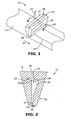
- the plurality of gas relief apertures 26 is array 27a of channels 26a.
- Array 27a extends across substantially the entire width of the internal cavity 28.
- Each channel 26a extends from internal cavity 28 to the environment surrounding die 12, so as to place internal cavity 28 in communication with the surrounding environment through each channel 26a.
- Array 27 of channels 26a ensures that no pockets of gas 29 can remain within the internal cavity 28 without means of egress.
- channels 26a are sized so as to allow egress of gas 29 from internal cavity 28 while substantially preventing egress of material 20.
- Opening 22a illustrates one example of where the supply pipe 22 (see FIG. 1 ) within the removed first portion 16 would open into the internal cavity 28.
- the top of opening 22a is disposed immediately adjacent the plurality of gas passages 26 in order to best achieve air removal from the internal cavity 28.
- channels 26a are illustrated as being disposed in second portion 18 of die 12, channels 26a may be disposed in either or both portions 16 and 18 of die 12, on an insert (e.g., insert 30, shown in FIG. 1 ) or may be disposed through a die configuration utilizing any number of portions to form an assembly including a single block.
- a roughened area 27b is provided adjacent internal cavity 28.
- this roughened area 27b can either be formed on either or both portions 16 and 18 of die 12, or on an insert (e.g., insert 30, shown in FIG. 1 ) or on a die configuration using any number of portions to form an assembly.
- the degree of roughness of roughened area 27b is calculated to provide interstices 26b (on die 12 and/or insert 30) that serve as gas relief passages 26.
- the sizing of gas relief passages 26 provided by the interstices 26b in the roughened area 27b should be sufficient to provide egress of gas from the internal cavity 28 to the environment surrounding the die 12, while still preventing the egress of more than a trivial amount of coating material 20 from the internal cavity 28.
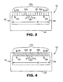
- Shim 40 is one example of insert 30, discussed previously with respect to FIG. 2 and is adapted to be positioned between the first portion 16 and the second portion 18 of die 12 (see FIG.'s 1 and 2). Utilizing shims in extrusion or coating dies is generally known in the art.
- dies are often assemblies held together by bolts, and so bolt holes 42 are shown in the illustrated embodiment of shim 40 to allow such bolts to pass.
- Bolting shim 40 in place between first and second portions 16 and 18 provides gas relief apertures 26 sized so as to create passages that allow egress of gas 29 from the die cavity, but do not allow egress of more than a trivial amount of coating (or extruding) material 20 from the die cavity.
- the plurality of gas relief apertures extends a distance of about the width of the die cavity 28 (see F1G.'s 3 and 4) of the assembled die 12.
- the shim can be removed and a different shim having different dimensions of channels 26a can be substituted to allow egress of gas 29, while substantially preventing egress of the coated or extruded material 29.
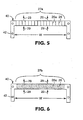
- FIG. 6 an alternate embodiment of shim 40 is illustrated.
- a roughened area 27b having interstices 26b is provided on shim 40.
- the interstices 26b in roughened area 27b provide gas relief passages 26 sufficient to provide egress to gas in the die cavity, but substantially preventing egress of coating (or extruding) material from the die cavity.
- a material having a roughened surface may be secured to shim 40 to provide roughened aread 27b.
- roughened area 27b may be formed directly in the material forming shim 40. It should be noted that roughening the surface can be accomplished using conventional means known to those skilled in the art.
- the present invention addresses the disadvantages inherent in the devices described above by providing practical designs for dies having multiple routes for residual gas to escape, even when the die must be oriented in a vertical direction.
- the invention can be thought of as a die including a die body having a cavity therein, wherein the cavity is in fluid communication with an applicator slot.
- a plurality of gas relief apertures are present in fluid communication with the cavity at positions in the cavity removed from the applicator slot.
- the invention can be thought of as a method of applying a material to a substrate.
- a die comprising a die body having a cavity therein is provided. Wherein the cavity is in fluid communication with an applicator slot. A plurality of gas relief apertures, in fluid communication with the cavity are present in the die. The gas relief apertures are disposed at positions in the cavity removed from the applicator slot.
- the die is oriented with the applicator slot generally downwards above the substrate.
- Material is then introduced into the die cavity such that the material is dispensed onto the substrate through the applicator slot and such that residual air within the die cavity is vented through the plurality of gas relief apertures.
- a coating die of generally conventional construction was prepared having a first and a second portion, together defining a die cavity communicating with an applicator slot about 5 inches (12.5 cm) long.
- the second die portion had a connection to a feed pipe and was constructed from steel.
- the first die portion was constructed from transparent acrylic polymer so that the die cavity could be seen during coating.
- the first and second portions were provided with bolt holes for assembly together to form the coating die.
- a shim (as generally depicted in Fig. 5 ) was fabricated from stainless steel plate having a thickness of about 0.01 inch (0.25 mm). Multiple gas relief passages were milled onto one of the surfaces of the shim (again as generally depicted in Fig. 5 ).
- the pressure in the die for the given set of coating conditions was calculated, and then the size of the passages were determined such that the flow across the passage due to the effect of the operating pressure is ⁇ 0.001 cc/min.
- the coating die was assembled using bolts with the described shim between the first and second portions such that the exit of the feed pipe was immediately below the level of the gas relief passages.
- the die slot was sealed closed and the die was filled with coating material.
- the die slot was sealed closed to allow the die cavity to be filled without any leakage of the coating material.
- the coating die was set up for die coating with the gas relief passages oriented upwards and the applicator slot oriented downwards.
- the coating die was then used to coat a solution of glycerin and water at room temperature, having a viscosity of about 30 centipoises, onto a moving substrate.
- the pressure in the die cavity was about 0.33 psi (2.3 kPa).
- a coating die of generally conventional construction was prepared having a first and a second portion, both formed from steel, together defining a die cavity communicating with an applicator slot about 4 inches (10.16 cm) long.
- the second die portion had a connection to a feed pipe.
- the first and second portions were provided with bolt holes for assembly together to form the coating die.
- a shim (as generally depicted in Fig. 6 ) was fabricated from stainless steel plate having a thickness of about 0.04 inch (1.0 mm).
- Multiple gas relief passages were formed onto one of the surfaces of the shim (again as generally depicted in Fig. 6 ). These gas relief passages were formed by mounting 240 grit sandpaper (approximately 60 micrometer roughness) to the surface of the shim.
- the coating die was assembled using bolts with the described shim between the first and second portions such that the exit of the feed pipe was immediately below the level of the gas relief passages.
- the die slot was sealed closed and the die was filled with water at room temperature, having a viscosity of about 1 centipoise (coating material).
- the die slot was sealed closed to allow the die cavity to be filled without any leakage of the coating material.
- the coating die was set up for die coating with the gas relief passages oriented upwards and the applicator slot oriented downwards.
- the pressure in the die cavity was about 0.1 psi (0.69 kPa).
- the from of the die was removed and complete filling of the internal cavity was verified by opening the die to reveal the cavity and view the location of the liquid air interface (the "wetted" surface) in the cavity, as indicated by the blue dye. Viewing the die cavity revealed that the air within the cavity was vented as the water had entered into the channels between the sandpaper grit. Additionally, coating material was not lost through the gas relief passages to the environment surrounding the die.
Landscapes
- Engineering & Computer Science (AREA)
- Mechanical Engineering (AREA)
- Coating Apparatus (AREA)
- Application Of Or Painting With Fluid Materials (AREA)
- Moulds For Moulding Plastics Or The Like (AREA)
Applications Claiming Priority (2)
| Application Number | Priority Date | Filing Date | Title |
|---|---|---|---|
| US10/439,448 US7083826B2 (en) | 2003-05-16 | 2003-05-16 | Coating die and method for use |
| EP04785479A EP1624973B1 (en) | 2003-05-16 | 2004-04-13 | Coating die and method for use |
Related Parent Applications (2)
| Application Number | Title | Priority Date | Filing Date |
|---|---|---|---|
| EP04785479A Division EP1624973B1 (en) | 2003-05-16 | 2004-04-13 | Coating die and method for use |
| EP04785479.9 Division | 2004-04-13 |
Publications (2)
| Publication Number | Publication Date |
|---|---|
| EP2072148A1 EP2072148A1 (en) | 2009-06-24 |
| EP2072148B1 true EP2072148B1 (en) | 2011-12-07 |
Family
ID=33417801
Family Applications (2)
| Application Number | Title | Priority Date | Filing Date |
|---|---|---|---|
| EP09002791A Expired - Lifetime EP2072148B1 (en) | 2003-05-16 | 2004-04-13 | Coating die |
| EP04785479A Expired - Lifetime EP1624973B1 (en) | 2003-05-16 | 2004-04-13 | Coating die and method for use |
Family Applications After (1)
| Application Number | Title | Priority Date | Filing Date |
|---|---|---|---|
| EP04785479A Expired - Lifetime EP1624973B1 (en) | 2003-05-16 | 2004-04-13 | Coating die and method for use |
Country Status (7)
Families Citing this family (20)
| Publication number | Priority date | Publication date | Assignee | Title |
|---|---|---|---|---|
| KR20020015785A (ko) * | 2000-08-23 | 2002-03-02 | 고성달 | 피혁의 염색방법 |
| US7083826B2 (en) * | 2003-05-16 | 2006-08-01 | 3M Innovative Properties Company | Coating die and method for use |
| CA2514260C (en) * | 2003-11-24 | 2009-09-15 | Central Products Company | Process for preparing adhesive using planetary extruder |
| CA2566078C (en) * | 2004-05-13 | 2013-09-10 | Dsm Ip Assets B.V. | Apparatus and process for the formation of a film of fibre |
| DE602006005164D1 (de) * | 2005-07-13 | 2009-03-26 | Agfa Gevaert Nv | Verfahren zur breitschlitzextrusionsbeschichtung einer flüssigen zusammensetzung |
| US7621737B2 (en) * | 2006-07-19 | 2009-11-24 | 3M Innovative Properties Company | Die with insert and gas purging method for die |
| JP5007168B2 (ja) * | 2007-07-10 | 2012-08-22 | 日東電工株式会社 | ダイコーター調整方法及び光学フィルムの製造方法 |
| KR20100101635A (ko) * | 2007-12-31 | 2010-09-17 | 쓰리엠 이노베이티브 프로퍼티즈 컴파니 | 코팅성 물질의 도포방법 |
| KR101014659B1 (ko) * | 2008-07-09 | 2011-02-16 | (주)티에스티아이테크 | 유체 토출장치 |
| KR101107651B1 (ko) * | 2011-07-27 | 2012-01-20 | 성안기계 (주) | 도포 균일성이 향상된 슬롯다이 |
| JP6055280B2 (ja) * | 2012-11-11 | 2016-12-27 | 平田機工株式会社 | 塗布液充填方法 |
| JP6068271B2 (ja) * | 2013-06-10 | 2017-01-25 | 東レ株式会社 | 塗布器、及び塗布装置 |
| JP6196916B2 (ja) * | 2014-02-25 | 2017-09-13 | 東京応化工業株式会社 | ノズルおよび塗布装置 |
| JP6309407B2 (ja) * | 2014-09-17 | 2018-04-11 | 東レ株式会社 | 塗布器、塗布装置、及び塗布方法 |
| CN108602086A (zh) * | 2016-02-12 | 2018-09-28 | 3M创新有限公司 | 具有主动受控涂覆宽度的狭缝模具 |
| JP6967477B2 (ja) * | 2018-03-22 | 2021-11-17 | 東レ株式会社 | 塗布器、及び塗布器のエア排出方法 |
| KR102368359B1 (ko) * | 2019-05-14 | 2022-02-25 | 주식회사 엘지에너지솔루션 | 에어 벤트를 포함하는 슬롯 다이 코팅 장치 |
| US20230249216A1 (en) * | 2020-09-28 | 2023-08-10 | Lg Energy Solution, Ltd. | Multi-Slot Die Coater |
| EP4528837A3 (en) * | 2020-11-13 | 2025-06-11 | LG Energy Solution, Ltd. | Dual slot die coater including air vent |
| CN113171889B (zh) * | 2021-04-27 | 2022-07-12 | 常州瑞择微电子科技有限公司 | 水帘喷头 |
Family Cites Families (21)
| Publication number | Priority date | Publication date | Assignee | Title |
|---|---|---|---|---|
| US3023456A (en) * | 1959-08-03 | 1962-03-06 | Dow Chemical Co | Extruder apparatus |
| US3889633A (en) * | 1974-05-08 | 1975-06-17 | Formulabs Ind Inks Inc | Apparatus for applying one or more stripes to conductors |
| NL162753C (nl) * | 1974-06-07 | 1980-06-16 | Hoechst Ag | Werkwijze voor het opbrengen van een bekledingslaag op een draagband, alsmede inrichting voor het toepassen van deze werkwijze. |
| US4491417A (en) * | 1983-04-29 | 1985-01-01 | Usm Corporation | Devolatilizing mixing extruder |
| US4938994A (en) * | 1987-11-23 | 1990-07-03 | Epicor Technology, Inc. | Method and apparatus for patch coating printed circuit boards |
| JPH074399Y2 (ja) * | 1989-08-28 | 1995-02-01 | 石川島播磨重工業株式会社 | 給油量制御装置 |
| JP2816510B2 (ja) * | 1991-01-23 | 1998-10-27 | 東京エレクトロン株式会社 | 液体供給ノズル |
| KR100230753B1 (ko) * | 1991-01-23 | 1999-11-15 | 도꾜 일렉트론 큐슈리미티드 | 액도포 시스템 |
| JPH0515828A (ja) * | 1991-07-09 | 1993-01-26 | Kanzaki Paper Mfg Co Ltd | 加圧型カーテン塗布装置 |
| CA2098784A1 (en) * | 1992-07-08 | 1994-01-09 | Bentley Boger | Apparatus and methods for applying conformal coatings to electronic circuit boards |
| JP2537739B2 (ja) * | 1992-07-31 | 1996-09-25 | 三菱化学株式会社 | ダイコ―タ |
| US5702527A (en) * | 1995-02-22 | 1997-12-30 | Minnesota Mining And Manufacturing Company | Restricted flow die |
| JPH10277464A (ja) | 1997-04-02 | 1998-10-20 | Dainippon Printing Co Ltd | 塗布装置及びこれを使用する塗布方法 |
| JPH11188301A (ja) | 1997-12-26 | 1999-07-13 | Hirata Corp | 流体塗布装置 |
| US6319316B1 (en) * | 1998-02-17 | 2001-11-20 | Fastar, Ltd. | System and method for performing low contamination extrusion for microelectronics applications |
| US6548115B1 (en) | 1998-11-30 | 2003-04-15 | Fastar, Ltd. | System and method for providing coating of substrates |
| JP2002119907A (ja) * | 2000-10-12 | 2002-04-23 | Konica Corp | 押出し塗布装置およびエア抜き方法 |
| GB0030182D0 (en) | 2000-12-11 | 2001-01-24 | Univ Brunel | Material processing |
| JP2003071368A (ja) * | 2001-09-06 | 2003-03-11 | Matsushita Electric Ind Co Ltd | 液体塗布方法及び液体塗布装置、並びにこれを用いた陰極線管の製造方法及び装置 |
| JP2003340335A (ja) * | 2002-05-27 | 2003-12-02 | Okazaki Kikai Kogyo Kk | 周面浸漬型のグラビアコータ |
| US7083826B2 (en) * | 2003-05-16 | 2006-08-01 | 3M Innovative Properties Company | Coating die and method for use |
-
2003
- 2003-05-16 US US10/439,448 patent/US7083826B2/en not_active Expired - Lifetime
-
2004
- 2004-04-13 EP EP09002791A patent/EP2072148B1/en not_active Expired - Lifetime
- 2004-04-13 WO PCT/US2004/011274 patent/WO2004103578A1/en active Application Filing
- 2004-04-13 AT AT04785479T patent/ATE427788T1/de not_active IP Right Cessation
- 2004-04-13 EP EP04785479A patent/EP1624973B1/en not_active Expired - Lifetime
- 2004-04-13 DE DE602004020458T patent/DE602004020458D1/de not_active Expired - Lifetime
- 2004-04-13 KR KR1020057021719A patent/KR101087384B1/ko not_active Expired - Fee Related
- 2004-04-13 JP JP2006532403A patent/JP4685783B2/ja not_active Expired - Fee Related
-
2006
- 2006-07-26 US US11/459,980 patent/US7695768B2/en not_active Expired - Fee Related
Also Published As
| Publication number | Publication date |
|---|---|
| EP2072148A1 (en) | 2009-06-24 |
| US7083826B2 (en) | 2006-08-01 |
| JP4685783B2 (ja) | 2011-05-18 |
| US20060257574A1 (en) | 2006-11-16 |
| DE602004020458D1 (de) | 2009-05-20 |
| US7695768B2 (en) | 2010-04-13 |
| KR20060009935A (ko) | 2006-02-01 |
| WO2004103578A1 (en) | 2004-12-02 |
| US20040228972A1 (en) | 2004-11-18 |
| JP2007504001A (ja) | 2007-03-01 |
| EP1624973B1 (en) | 2009-04-08 |
| ATE427788T1 (de) | 2009-04-15 |
| EP1624973A1 (en) | 2006-02-15 |
| KR101087384B1 (ko) | 2011-11-25 |
Similar Documents
| Publication | Publication Date | Title |
|---|---|---|
| US7695768B2 (en) | Coating die and method for use | |
| US7685693B2 (en) | Method of forming coating die with expansible chamber device | |
| EP2582470B1 (en) | Distribution manifold with multiple dispensing needles | |
| CA2301540C (en) | Coating apparatus | |
| JPH0238711A (ja) | 線圧縮力が制御可能なロール | |
| JP2965736B2 (ja) | 輪転印刷機のためのインキ装置 | |
| CA2237950C (en) | Process and apparatus for direct chill casting | |
| JP2001062368A (ja) | 塗布装置および塗布方法 | |
| FI107834B (fi) | Taipumasäädetty tela | |
| US12083552B2 (en) | Adhesive dispenser with slotted nozzle assembly | |
| US4450226A (en) | Method and apparatus for producing a printing plate | |
| TWI280158B (en) | Die lip for strip coating | |
| US3970119A (en) | Method and apparatus for manufacture of disposable thermometers | |
| JP3072336B2 (ja) | 間欠塗工装置 | |
| JP2004321911A (ja) | 塗布工具及び塗布装置 | |
| US4403566A (en) | Apparatus for producing a printing plate | |
| JP2981873B2 (ja) | 塗工装置 | |
| JP2004230361A (ja) | スリットダイコーターヘッド | |
| JPH02172555A (ja) | リップコータ型塗工装置 | |
| JP2981874B2 (ja) | 塗工装置 | |
| JP5877841B2 (ja) | パッチコーティングダイ | |
| US20250188792A1 (en) | Device for Distributing Sealant Materials and Methods of Using the Same | |
| EP3013588B1 (en) | Printhead structure | |
| JP2000343017A (ja) | 塗工装置 | |
| KR100802536B1 (ko) | 슬릿형 코팅장치 |
Legal Events
| Date | Code | Title | Description |
|---|---|---|---|
| PUAI | Public reference made under article 153(3) epc to a published international application that has entered the european phase |
Free format text: ORIGINAL CODE: 0009012 |
|
| AC | Divisional application: reference to earlier application |
Ref document number: 1624973 Country of ref document: EP Kind code of ref document: P |
|
| AK | Designated contracting states |
Kind code of ref document: A1 Designated state(s): AT BE BG CH CY CZ DE DK EE ES FI FR GB GR HU IE IT LI LU MC NL PL PT RO SE SI SK TR |
|
| 17P | Request for examination filed |
Effective date: 20091224 |
|
| AKX | Designation fees paid |
Designated state(s): DE |
|
| 17Q | First examination report despatched |
Effective date: 20100420 |
|
| RTI1 | Title (correction) |
Free format text: COATING DIE |
|
| GRAP | Despatch of communication of intention to grant a patent |
Free format text: ORIGINAL CODE: EPIDOSNIGR1 |
|
| RIN1 | Information on inventor provided before grant (corrected) |
Inventor name: NOYOLA, JOAN M. Inventor name: SECOR, ROBERT B. Inventor name: PEKUROVSKY, MIKHAIL L. |
|
| GRAS | Grant fee paid |
Free format text: ORIGINAL CODE: EPIDOSNIGR3 |
|
| GRAA | (expected) grant |
Free format text: ORIGINAL CODE: 0009210 |
|
| AC | Divisional application: reference to earlier application |
Ref document number: 1624973 Country of ref document: EP Kind code of ref document: P |
|
| AK | Designated contracting states |
Kind code of ref document: B1 Designated state(s): DE |
|
| REG | Reference to a national code |
Ref country code: DE Ref legal event code: R096 Ref document number: 602004035627 Country of ref document: DE Effective date: 20120223 |
|
| PLBE | No opposition filed within time limit |
Free format text: ORIGINAL CODE: 0009261 |
|
| STAA | Information on the status of an ep patent application or granted ep patent |
Free format text: STATUS: NO OPPOSITION FILED WITHIN TIME LIMIT |
|
| 26N | No opposition filed |
Effective date: 20120910 |
|
| REG | Reference to a national code |
Ref country code: DE Ref legal event code: R097 Ref document number: 602004035627 Country of ref document: DE Effective date: 20120910 |
|
| PGFP | Annual fee paid to national office [announced via postgrant information from national office to epo] |
Ref country code: DE Payment date: 20180404 Year of fee payment: 15 |
|
| REG | Reference to a national code |
Ref country code: DE Ref legal event code: R119 Ref document number: 602004035627 Country of ref document: DE |
|
| PG25 | Lapsed in a contracting state [announced via postgrant information from national office to epo] |
Ref country code: DE Free format text: LAPSE BECAUSE OF NON-PAYMENT OF DUE FEES Effective date: 20191101 |