EP2071617A2 - Tampon surélevé et son procédé de transfert - Google Patents
Tampon surélevé et son procédé de transfert Download PDFInfo
- Publication number
- EP2071617A2 EP2071617A2 EP08020463A EP08020463A EP2071617A2 EP 2071617 A2 EP2071617 A2 EP 2071617A2 EP 08020463 A EP08020463 A EP 08020463A EP 08020463 A EP08020463 A EP 08020463A EP 2071617 A2 EP2071617 A2 EP 2071617A2
- Authority
- EP
- European Patent Office
- Prior art keywords
- support member
- raceway
- shelf
- overhead
- attached
- Prior art date
- Legal status (The legal status is an assumption and is not a legal conclusion. Google has not performed a legal analysis and makes no representation as to the accuracy of the status listed.)
- Withdrawn
Links
Images


Classifications
-
- H—ELECTRICITY
- H01—ELECTRIC ELEMENTS
- H01L—SEMICONDUCTOR DEVICES NOT COVERED BY CLASS H10
- H01L21/00—Processes or apparatus adapted for the manufacture or treatment of semiconductor or solid state devices or of parts thereof
- H01L21/67—Apparatus specially adapted for handling semiconductor or electric solid state devices during manufacture or treatment thereof; Apparatus specially adapted for handling wafers during manufacture or treatment of semiconductor or electric solid state devices or components ; Apparatus not specifically provided for elsewhere
- H01L21/677—Apparatus specially adapted for handling semiconductor or electric solid state devices during manufacture or treatment thereof; Apparatus specially adapted for handling wafers during manufacture or treatment of semiconductor or electric solid state devices or components ; Apparatus not specifically provided for elsewhere for conveying, e.g. between different workstations
- H01L21/67763—Apparatus specially adapted for handling semiconductor or electric solid state devices during manufacture or treatment thereof; Apparatus specially adapted for handling wafers during manufacture or treatment of semiconductor or electric solid state devices or components ; Apparatus not specifically provided for elsewhere for conveying, e.g. between different workstations the wafers being stored in a carrier, involving loading and unloading
- H01L21/67766—Mechanical parts of transfer devices
-
- B—PERFORMING OPERATIONS; TRANSPORTING
- B65—CONVEYING; PACKING; STORING; HANDLING THIN OR FILAMENTARY MATERIAL
- B65G—TRANSPORT OR STORAGE DEVICES, e.g. CONVEYORS FOR LOADING OR TIPPING, SHOP CONVEYOR SYSTEMS OR PNEUMATIC TUBE CONVEYORS
- B65G1/00—Storing articles, individually or in orderly arrangement, in warehouses or magazines
- B65G1/02—Storage devices
- B65G1/04—Storage devices mechanical
- B65G1/0457—Storage devices mechanical with suspended load carriers
-
- H—ELECTRICITY
- H01—ELECTRIC ELEMENTS
- H01L—SEMICONDUCTOR DEVICES NOT COVERED BY CLASS H10
- H01L21/00—Processes or apparatus adapted for the manufacture or treatment of semiconductor or solid state devices or of parts thereof
- H01L21/67—Apparatus specially adapted for handling semiconductor or electric solid state devices during manufacture or treatment thereof; Apparatus specially adapted for handling wafers during manufacture or treatment of semiconductor or electric solid state devices or components ; Apparatus not specifically provided for elsewhere
- H01L21/677—Apparatus specially adapted for handling semiconductor or electric solid state devices during manufacture or treatment thereof; Apparatus specially adapted for handling wafers during manufacture or treatment of semiconductor or electric solid state devices or components ; Apparatus not specifically provided for elsewhere for conveying, e.g. between different workstations
- H01L21/67703—Apparatus specially adapted for handling semiconductor or electric solid state devices during manufacture or treatment thereof; Apparatus specially adapted for handling wafers during manufacture or treatment of semiconductor or electric solid state devices or components ; Apparatus not specifically provided for elsewhere for conveying, e.g. between different workstations between different workstations
- H01L21/67727—Apparatus specially adapted for handling semiconductor or electric solid state devices during manufacture or treatment thereof; Apparatus specially adapted for handling wafers during manufacture or treatment of semiconductor or electric solid state devices or components ; Apparatus not specifically provided for elsewhere for conveying, e.g. between different workstations between different workstations using a general scheme of a conveying path within a factory
-
- H—ELECTRICITY
- H01—ELECTRIC ELEMENTS
- H01L—SEMICONDUCTOR DEVICES NOT COVERED BY CLASS H10
- H01L21/00—Processes or apparatus adapted for the manufacture or treatment of semiconductor or solid state devices or of parts thereof
- H01L21/67—Apparatus specially adapted for handling semiconductor or electric solid state devices during manufacture or treatment thereof; Apparatus specially adapted for handling wafers during manufacture or treatment of semiconductor or electric solid state devices or components ; Apparatus not specifically provided for elsewhere
- H01L21/677—Apparatus specially adapted for handling semiconductor or electric solid state devices during manufacture or treatment thereof; Apparatus specially adapted for handling wafers during manufacture or treatment of semiconductor or electric solid state devices or components ; Apparatus not specifically provided for elsewhere for conveying, e.g. between different workstations
- H01L21/67703—Apparatus specially adapted for handling semiconductor or electric solid state devices during manufacture or treatment thereof; Apparatus specially adapted for handling wafers during manufacture or treatment of semiconductor or electric solid state devices or components ; Apparatus not specifically provided for elsewhere for conveying, e.g. between different workstations between different workstations
- H01L21/67733—Overhead conveying
-
- H—ELECTRICITY
- H01—ELECTRIC ELEMENTS
- H01L—SEMICONDUCTOR DEVICES NOT COVERED BY CLASS H10
- H01L21/00—Processes or apparatus adapted for the manufacture or treatment of semiconductor or solid state devices or of parts thereof
- H01L21/67—Apparatus specially adapted for handling semiconductor or electric solid state devices during manufacture or treatment thereof; Apparatus specially adapted for handling wafers during manufacture or treatment of semiconductor or electric solid state devices or components ; Apparatus not specifically provided for elsewhere
- H01L21/677—Apparatus specially adapted for handling semiconductor or electric solid state devices during manufacture or treatment thereof; Apparatus specially adapted for handling wafers during manufacture or treatment of semiconductor or electric solid state devices or components ; Apparatus not specifically provided for elsewhere for conveying, e.g. between different workstations
- H01L21/67763—Apparatus specially adapted for handling semiconductor or electric solid state devices during manufacture or treatment thereof; Apparatus specially adapted for handling wafers during manufacture or treatment of semiconductor or electric solid state devices or components ; Apparatus not specifically provided for elsewhere for conveying, e.g. between different workstations the wafers being stored in a carrier, involving loading and unloading
- H01L21/67775—Docking arrangements
-
- B—PERFORMING OPERATIONS; TRANSPORTING
- B65—CONVEYING; PACKING; STORING; HANDLING THIN OR FILAMENTARY MATERIAL
- B65G—TRANSPORT OR STORAGE DEVICES, e.g. CONVEYORS FOR LOADING OR TIPPING, SHOP CONVEYOR SYSTEMS OR PNEUMATIC TUBE CONVEYORS
- B65G2201/00—Indexing codes relating to handling devices, e.g. conveyors, characterised by the type of product or load being conveyed or handled
- B65G2201/02—Articles
- B65G2201/0297—Wafer cassette
-
- Y—GENERAL TAGGING OF NEW TECHNOLOGICAL DEVELOPMENTS; GENERAL TAGGING OF CROSS-SECTIONAL TECHNOLOGIES SPANNING OVER SEVERAL SECTIONS OF THE IPC; TECHNICAL SUBJECTS COVERED BY FORMER USPC CROSS-REFERENCE ART COLLECTIONS [XRACs] AND DIGESTS
- Y10—TECHNICAL SUBJECTS COVERED BY FORMER USPC
- Y10S—TECHNICAL SUBJECTS COVERED BY FORMER USPC CROSS-REFERENCE ART COLLECTIONS [XRACs] AND DIGESTS
- Y10S414/00—Material or article handling
- Y10S414/135—Associated with semiconductor wafer handling
- Y10S414/14—Wafer cassette transporting
Definitions
- the present invention relates to improvement of an overhead buffer used in combination with an overhead traveling vehicle or the like.
- Patent Document 1 Japanese Laid-Open Patent Publication No. 2006-324469 discloses that an overhead buffer is provided on one side of a traveling rail of an overhead traveling vehicle to temporarily place an article conveyed by the overhead traveling vehicle.
- the article can be temporarily placed in the adjacent overhead buffer when an objective load port is filled, and the article can be carried in when the load port becomes available.
- the overhead traveling vehicle that conveys an article from a load port in a pickup position to a conveyance destination cannot be assigned, the article is conveyed to an overhead buffer in the vicinity of the pickup position, so that the load port in the pickup position can be made available.
- the overhead buffer often corresponds to the load port of a processing device, and more overhead buffers are often provided, or the overhead buffer is often transferred in accordance with the installation, transfer or the like of the processing device.
- the load port is a carrying-in and out location of an article provided in the processing device.
- the overhead buffer may also be simply referred to as a buffer.
- Patent Document 1 one of the right and left sides of the buffer is supported by the traveling rail of the overhead traveling vehicle, and the other is hung from a ceiling by columns.
- the ceiling of a clean room tends to be higher, and hanging the buffer from the ceiling by the columns such as hanging bolts involves high-place work during moving the buffer. This makes the transfer of the buffer difficult.
- An object of the present invention is to make the transfer of an overhead buffer easier.
- An overhead buffer of the present invention is an overhead buffer supporting a shelf allowing an article to be freely passed and received between an overhead traveling vehicle and itself, by a support member extending in a vertical direction, characterized in that:
- a method for transferring an overhead buffer that supports a shelf allowing an article to be freely passed and received between an overhead traveling vehicle and itself, by a support member extending in a vertical direction characterized by including the steps of:
- the shelf is made of a second raceway attached to the second support member and having an opening along the horizontal direction, and a placement member for the article supported slidably in the horizontal direction by the second raceway.
- the second support member is made of support members on both ends of the shelf, and a support member in a middle portion of the shelf, the support member in the middle portion of the shelf is horizontally slidable along the first raceway and the second raceway, and attachment members each including two pieces forming an L shape and a joining portion that joins the two pieces are arranged on both front and rear sides of the second support member along the opening of the first raceway, and one of the L-shaped two pieces is attached to the raceway, and the other piece is attached to the second support member.
- the overhead buffer can be transferred easily. Moreover, since the first support member is attached to the ceiling, and the second support member is attached to the raceway, a length of the shelf of the buffer is not limited by the attachment pitch to the ceiling.
- the second raceway By making up the shelf by the second raceway attached to the second support member, and the placement member for the article supported slidably in the horizontal direction by the second raceway, a placement position can be easily changed. Furthermore, once the one piece of the L-shaped attachment member is attached to the second support member and the other piece is attached to the first raceway to join the two pieces of the L shape, the second support member can be solidly attached to the first raceway. Therefore, no beam for mutually joining the second support members is required. When the second support member supporting the middle portion of the shelf is slid along the first and second raceways, the arrangement of the placement member on the shelf can be changed easily.
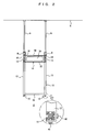
- Fig. 1 is a side view of essential parts of an overhead buffer of an embodiment.
- Fig. 2 is a front view of the overhead buffer of the embodiment.
- Fig. 3 is a front view showing the overhead buffer and an overhead traveling vehicle.
- Fig. 4 is a plane view of a lower support member and attachment members according to the embodiment.
- Fig. 5 is a side view showing a state where the lower support member is attached to an upper raceway according to the embodiment.
- Fig. 6 is a view showing attachment of a sheet to the lower raceway according to the embodiment.
- Fig. 7 is a side view of essential parts of the overhead buffer in which a position of the lower support member is changed from that of Fig. 1 .
- FIGs. 1 to 7 an overhead buffer 2 of one embodiment is shown.
- Reference numeral 4 denotes a ceiling of a clean room or the like, to which hanging bolts 6 are attached at a fixed pitch.
- Reference numeral 8 denotes an upper raceway, and its structure is shown as an enlarged view in a lower right portion of Fig. 1 .
- the raceway 8 has no opening along the longitudinal direction in the upper surface, and thus, through-holes are provided in the upper surface of the raceway 8 in appropriate positions to fix the hanging bolts 6 by the nuts 34.
- a buffer unit 10 is provided under the raceway 8.
- Reference numeral 12 denotes a lower support member
- reference numeral 14 denotes an attachment member for attaching both front and rear sides of the lower support member 12 to the raceway 8 using the opening 32
- reference numeral 15 denotes a triangle-shaped reinforcement plate connecting both pieces of an L shape of the attachment member 14.
- Reference numeral 16 denotes a lower raceway to which a plurality of sheets 18 on a tray for placing an article such as an FOUP are attached. Appropriate bars may be used in place of the lower raceways 16, and as the lower support members 12, while three support members 12a to 12c are used here, two support members that support both ends of the buffer unit 10 may be used.
- the gap is set to a relatively large value g2, and in the case where the lower support member 12b does not interpose, it is set to a relatively small value g1.
- the plurality of buffer units 10 are attached in appropriate positions along the raceways 8.
- the overhead buffer 2 passes and receives an article such as an FOUP 26 between an overhead traveling vehicle system and itself.
- a rail 20 is supported from the ceiling 4 by hanging bolts 22 to run an overhead traveling vehicle 24.
- the overhead traveling vehicle 24 moves up and down the FOUP 26 by a hoist 28, and advances and retracts the hoist 28 and the FOUP 26 by a lateral drive 30 horizontally and perpendicularly to the rail 20 to pass and receive the FOUP 26 between the sheet 18 and itself.
- Fig. 2 shows a front view of the overhead buffer 2, and a pair of right and left hanging bolts 6, 6 extends from the ceiling 4 downward in a vertical direction to support the upper raceways 8 whose longitudinal direction is horizontal.
- the pair of right and left vertical lower support members 12 is attached to the upper raceways 8 through the attachment members 14, and the sheets 18 are attached to the bottom portions of the lower support members 12 through the lower raceways 16 whose longitudinal direction is horizontal.
- Each of the attachment members 14 is made of metal, joins the right and left lower support members 12, 12, and includes plates 36, 37 forming two pieces of the L shape. In the plates 36, 37, openings 38, 39 are provided for reducing weight. Further, the plates 36, 37 are joined and reinforced by the reinforcement plate 15. As shown in Figs. 4, 5 , the attachment members 14,14 are attached to the front and rear sides of each of the lower support members 12, that is, in the longitudinal direction of the raceway 8, respectively, and the plates 36 are attached to bottom surfaces of the raceways 8 by bolts and nut plates 42 and the like, and the plates 37 are attached to the lower support members 12 by bolts.
- the nut plate 42 is a plate provided with a nut, and is slidable inside the raceway 8.
- the attachment members 14 allow the right and left lower support members 12 to be joined to each other, and the lower support members 12 are prevented from being swung back and forth, that is, along the longitudinal direction of the raceways 8. Thus, no brace is required in an intermediate position of the raceway 8 and the raceway 16. As shown in a lower right portion of Fig. 5 , terminal portions of the plates 36, 37 may be joined by a brace 45 or the like in place of the reinforcement plate 15.
- the lower raceway 16 has four openings, for example, along the longitudinal direction, and utilizing these openings, is attached to the lower support member 12 by bolts 40, 41 and the like. Then, the sheet 18 is fixed to the lower raceway 16, utilizing a bolt 50, and the upper opening of the lower raceway 16 or the like, as shown in Fig. 6 .
- the hanging bolts 6 can be freely attached to the ceiling 4 only at the predetermined pitch. At this pitch, the hanging bolts 6 are attached in two right and left rows, and the upper raceways 8 are fixed to the lower ends.
- the plates 36 of the attachment members 14 are temporarily attached to the upper raceways 8, and the lower support members 12 are firmly fixed to the plates 37.
- the lower raceways 16 are attached to the lower support members 12, and the sheets 18 are attached. In this process, since the lower support members 12 are slidable along the upper raceways 8, the positions can be adjusted.
- the lower support members 12 are fixed to the upper raceways 8
- the lower raceways 16 are fixed to the lower support members 12, and the sheets 18 are fixed to the lower raceways 16.
- the buffer unit 10 may be assembled in advance, and then, may be attached to the upper raceways 8.
- Fig. 3 shows a relation between the overhead traveling vehicle 24 and the overhead buffer 2.
- the overhead traveling vehicle 24 includes a traveling drive part and a power receiving part inside the rail 20, and travels along the rail 20, and receives power from the rail 20 side by non-contact power feeding or the like.
- a ⁇ drive 27 to the FOUP 26 are moved laterally by the lateral drive 30, and the orientation of the hoist 28 and the FOUP 26 is turned in a horizontal plane by the ⁇ drive 27.
- the hoist 28 moves up and down the FOUP 26, and chucks and releases an upper flange of the FOUP 26 by a chuck 29.
- a safety cover 31 prevents the FOUP 26 from falling.
- the overhead traveling vehicle 24 can freely pass and receive the FOUP 26 between the sheets 18, a load port not shown and the like, and itself.
- the buffer unit 10 With the movement of the processing device or the like in the clean room, there may arise a need for transferring the buffer unit 10. This is because the buffer unit 10 is often provided in a position opposed to the processing device, or the like. When the buffer unit 10 is transferred, the attachment of the attachment members 14 to the upper raceways 8 is loosened, the entire buffer unit 10 can be slid along the raceways 8. This allows the buffer unit 10 to be transferred extremely easily. Moreover, with the exchange of the processing device, there may arise a need for adjusting the positions of the individual sheets 18a to 18d. In this case, the lower support members 12a, 12c on both ends of the buffer unit 10 are not moved, but a position of the lower support members 12b in the middle is moved.
- the fixation of the lower support members 12b in the middle to the raceways 8, 16 is made weak to slide them to predetermined positions.
- the sheet 18c or the like is moved along the raceways 16. This can change the gap between the sheets 18b, 18c, and the gap between the sheets 18c, 18d. It is because no braces joining the lower support members 12a to 12c in intermediate positions in a height direction and so on are present that the lower support members 12b can be slid alone.
- the buffer unit 10 of the embodiment is arranged for example, on the side of, and parallel to the rail 20 of the overhead traveling vehicle 24, the buffer unit 10 may be arranged under the rail 20.
Applications Claiming Priority (1)
| Application Number | Priority Date | Filing Date | Title |
|---|---|---|---|
| JP2007318332A JP5163866B2 (ja) | 2007-12-10 | 2007-12-10 | 天井バッファとその移設方法 |
Publications (2)
| Publication Number | Publication Date |
|---|---|
| EP2071617A2 true EP2071617A2 (fr) | 2009-06-17 |
| EP2071617A3 EP2071617A3 (fr) | 2011-11-02 |
Family
ID=40343562
Family Applications (1)
| Application Number | Title | Priority Date | Filing Date |
|---|---|---|---|
| EP08020463A Withdrawn EP2071617A3 (fr) | 2007-12-10 | 2008-11-25 | Tampon surélevé et son procédé de transfert |
Country Status (5)
| Country | Link |
|---|---|
| EP (1) | EP2071617A3 (fr) |
| JP (1) | JP5163866B2 (fr) |
| KR (1) | KR101236361B1 (fr) |
| CN (1) | CN101456487B (fr) |
| TW (1) | TWI414468B (fr) |
Cited By (1)
| Publication number | Priority date | Publication date | Assignee | Title |
|---|---|---|---|---|
| US11171027B2 (en) | 2017-05-19 | 2021-11-09 | Murata Machinery, Ltd. | Storing system |
Families Citing this family (13)
| Publication number | Priority date | Publication date | Assignee | Title |
|---|---|---|---|---|
| TWI488251B (zh) | 2012-10-19 | 2015-06-11 | Inotera Memories Inc | 軌道緩衝裝置及晶圓傳輸系統 |
| KR102490590B1 (ko) * | 2016-06-29 | 2023-01-20 | 세메스 주식회사 | 캐리어 이송 장치 |
| KR102512046B1 (ko) * | 2016-06-29 | 2023-03-20 | 세메스 주식회사 | 캐리어 이송 장치 |
| CN105931448B (zh) * | 2016-07-06 | 2019-07-12 | 北京爱德王智能科技有限公司 | 一种单通道多向传送系统 |
| KR102020234B1 (ko) * | 2017-09-08 | 2019-09-11 | 세메스 주식회사 | 레이스웨이 유닛 및 이를 갖는 oht |
| KR102080877B1 (ko) * | 2018-05-28 | 2020-02-24 | 세메스 주식회사 | 레이스웨이 유닛 및 이를 갖는 oht |
| KR102114413B1 (ko) * | 2018-07-25 | 2020-05-22 | 세메스 주식회사 | 천장 주행 시스템 |
| JP7235059B2 (ja) * | 2019-01-25 | 2023-03-08 | 村田機械株式会社 | 保管システム |
| CN109720765A (zh) * | 2019-01-26 | 2019-05-07 | 西安威仁自动化科技有限公司 | 一种自动存取物料装置 |
| KR102541299B1 (ko) * | 2020-09-23 | 2023-06-12 | 세메스 주식회사 | 물품 반송 시스템 |
| KR102361173B1 (ko) | 2021-01-22 | 2022-02-14 | 주식회사 에이치씨씨 | 반도체 제조에 사용되는 풉 저장장치 |
| KR102360920B1 (ko) | 2021-02-22 | 2022-02-14 | 주식회사 에이치씨씨 | 반도체 생산라인에서 사용되는 풉 저장 장치 |
| CN114582772B (zh) * | 2022-04-28 | 2022-08-02 | 长鑫存储技术有限公司 | 悬吊式暂存装置、水平调节系统、水平调节方法 |
Citations (3)
| Publication number | Priority date | Publication date | Assignee | Title |
|---|---|---|---|---|
| JP2001031368A (ja) * | 1999-07-22 | 2001-02-06 | Murata Mach Ltd | 搬送車システム |
| US20040109746A1 (en) | 2002-12-09 | 2004-06-10 | Murata Kikai Kabushiki Kaisha | Overhead travelling carriage system |
| US20050224315A1 (en) | 2003-11-13 | 2005-10-13 | Applied Materials, Inc. | Dynamically balanced substrate carrier handler |
Family Cites Families (8)
| Publication number | Priority date | Publication date | Assignee | Title |
|---|---|---|---|---|
| JP2892523B2 (ja) * | 1991-06-15 | 1999-05-17 | 松下電工株式会社 | 台所のハンギング装置 |
| JPH08288355A (ja) * | 1995-04-12 | 1996-11-01 | Nikon Corp | 基板搬送装置 |
| KR100400788B1 (ko) * | 1995-08-22 | 2004-04-14 | 가부시키가이샤 다이후쿠 | 이동선반설비 |
| JP3067682B2 (ja) * | 1997-03-13 | 2000-07-17 | 村田機械株式会社 | 天井走行車システム |
| JP2001284433A (ja) * | 2000-01-28 | 2001-10-12 | Sony Corp | 基板移載装置及び基板移載方法 |
| TWI246501B (en) * | 2003-02-03 | 2006-01-01 | Murata Machinery Ltd | Overhead traveling carriage system |
| JP4045451B2 (ja) * | 2003-12-26 | 2008-02-13 | 村田機械株式会社 | 天井走行車システム |
| JP4501843B2 (ja) * | 2005-11-04 | 2010-07-14 | 株式会社ダイフク | 転換設備 |
-
2007
- 2007-12-10 JP JP2007318332A patent/JP5163866B2/ja not_active Expired - Fee Related
-
2008
- 2008-10-16 TW TW97139751A patent/TWI414468B/zh not_active IP Right Cessation
- 2008-11-25 EP EP08020463A patent/EP2071617A3/fr not_active Withdrawn
- 2008-12-02 KR KR1020080120961A patent/KR101236361B1/ko active IP Right Grant
- 2008-12-08 CN CN 200810185722 patent/CN101456487B/zh not_active Expired - Fee Related
Patent Citations (3)
| Publication number | Priority date | Publication date | Assignee | Title |
|---|---|---|---|---|
| JP2001031368A (ja) * | 1999-07-22 | 2001-02-06 | Murata Mach Ltd | 搬送車システム |
| US20040109746A1 (en) | 2002-12-09 | 2004-06-10 | Murata Kikai Kabushiki Kaisha | Overhead travelling carriage system |
| US20050224315A1 (en) | 2003-11-13 | 2005-10-13 | Applied Materials, Inc. | Dynamically balanced substrate carrier handler |
Cited By (1)
| Publication number | Priority date | Publication date | Assignee | Title |
|---|---|---|---|---|
| US11171027B2 (en) | 2017-05-19 | 2021-11-09 | Murata Machinery, Ltd. | Storing system |
Also Published As
| Publication number | Publication date |
|---|---|
| TW200927620A (en) | 2009-07-01 |
| CN101456487A (zh) | 2009-06-17 |
| KR101236361B1 (ko) | 2013-02-22 |
| TWI414468B (zh) | 2013-11-11 |
| KR20090060940A (ko) | 2009-06-15 |
| CN101456487B (zh) | 2012-12-26 |
| EP2071617A3 (fr) | 2011-11-02 |
| JP5163866B2 (ja) | 2013-03-13 |
| JP2009137740A (ja) | 2009-06-25 |
Similar Documents
| Publication | Publication Date | Title |
|---|---|---|
| EP2071617A2 (fr) | Tampon surélevé et son procédé de transfert | |
| EP2060468B1 (fr) | Système aérien de convoyage avec élément de stockage latéral fixé aux rails de guidage et procédé de fixation de cet élément | |
| KR101516621B1 (ko) | 공작 기계 시스템 | |
| KR101684105B1 (ko) | 전기자동차용 고전압배터리 자동 장착 시스템 및 장치 그리고 방법 | |
| JP7235059B2 (ja) | 保管システム | |
| CN108349649A (zh) | 取出装置及保管装置 | |
| WO2010092463A1 (fr) | Chaîne d'assemblage de véhicule | |
| RU2651946C2 (ru) | Транспортное устройство верхнего расположения с модулями несущего каркаса | |
| JP5365597B2 (ja) | スタッカクレーン | |
| US10279445B2 (en) | Conveyance jig for separate type control panel | |
| JP5421172B2 (ja) | 溶接ライン | |
| KR20170137363A (ko) | 환자 이송용 스트레쳐카 | |
| US20090206048A1 (en) | Suspended platform for overhead traveling carriage | |
| CN102773641B (zh) | 一种焊线机下料部料盒承载装置 | |
| CN216511011U (zh) | 一种组合式输送机支脚结构 | |
| CN206977371U (zh) | 一种生产太阳能组件短边框的装配装置 | |
| JP5443795B2 (ja) | 建物ユニット内への物品積込装置 | |
| JP7286779B2 (ja) | 移載台および加工モジュールの移載構造 | |
| CN215885190U (zh) | 一种加热炉上三工位手动进出料装置 | |
| CN202571867U (zh) | 一种挖掘机动臂加工工装 | |
| KR20100053197A (ko) | 선체 블럭의 역경사부 작업용 작업대 | |
| JP3347895B2 (ja) | 走行架台装置 | |
| US10858228B2 (en) | Lifting and transport apparatus for a heavy load | |
| US10604381B2 (en) | Passenger conveyor lifting device and passenger conveyor lifting method | |
| JP2018172041A (ja) | ドア艤装ライン |
Legal Events
| Date | Code | Title | Description |
|---|---|---|---|
| PUAI | Public reference made under article 153(3) epc to a published international application that has entered the european phase |
Free format text: ORIGINAL CODE: 0009012 |
|
| AK | Designated contracting states |
Kind code of ref document: A2 Designated state(s): AT BE BG CH CY CZ DE DK EE ES FI FR GB GR HR HU IE IS IT LI LT LU LV MC MT NL NO PL PT RO SE SI SK TR |
|
| AX | Request for extension of the european patent |
Extension state: AL BA MK RS |
|
| PUAL | Search report despatched |
Free format text: ORIGINAL CODE: 0009013 |
|
| AK | Designated contracting states |
Kind code of ref document: A3 Designated state(s): AT BE BG CH CY CZ DE DK EE ES FI FR GB GR HR HU IE IS IT LI LT LU LV MC MT NL NO PL PT RO SE SI SK TR |
|
| AX | Request for extension of the european patent |
Extension state: AL BA MK RS |
|
| RIC1 | Information provided on ipc code assigned before grant |
Ipc: H01L 21/677 20060101ALI20110926BHEP Ipc: H01L 21/67 20060101AFI20110926BHEP |
|
| 17P | Request for examination filed |
Effective date: 20120316 |
|
| AKX | Designation fees paid |
Designated state(s): AT BE BG CH CY CZ DE DK EE ES FI FR GB GR HR HU IE IS IT LI LT LU LV MC MT NL NO PL PT RO SE SI SK TR |
|
| 17Q | First examination report despatched |
Effective date: 20151216 |
|
| STAA | Information on the status of an ep patent application or granted ep patent |
Free format text: STATUS: THE APPLICATION IS DEEMED TO BE WITHDRAWN |
|
| 18D | Application deemed to be withdrawn |
Effective date: 20160427 |