EP2067896A1 - Procédé destiné à la fabrication d'un feutre de machine, ainsi que feutre de machine - Google Patents
Procédé destiné à la fabrication d'un feutre de machine, ainsi que feutre de machine Download PDFInfo
- Publication number
- EP2067896A1 EP2067896A1 EP20070023459 EP07023459A EP2067896A1 EP 2067896 A1 EP2067896 A1 EP 2067896A1 EP 20070023459 EP20070023459 EP 20070023459 EP 07023459 A EP07023459 A EP 07023459A EP 2067896 A1 EP2067896 A1 EP 2067896A1
- Authority
- EP
- European Patent Office
- Prior art keywords
- threads
- longitudinal
- auxiliary carrier
- carrier web
- machine felt
- Prior art date
- Legal status (The legal status is an assumption and is not a legal conclusion. Google has not performed a legal analysis and makes no representation as to the accuracy of the status listed.)
- Granted
Links
- 238000000034 method Methods 0.000 title claims abstract description 43
- 238000004519 manufacturing process Methods 0.000 title claims abstract description 24
- 230000009471 action Effects 0.000 claims abstract description 10
- 238000004804 winding Methods 0.000 claims description 18
- 239000000654 additive Substances 0.000 claims description 15
- 230000000996 additive effect Effects 0.000 claims description 10
- 239000004745 nonwoven fabric Substances 0.000 claims description 10
- 239000000463 material Substances 0.000 claims description 9
- 230000000295 complement effect Effects 0.000 claims description 8
- 239000000835 fiber Substances 0.000 claims description 7
- 238000002844 melting Methods 0.000 claims description 6
- 230000008018 melting Effects 0.000 claims description 6
- 230000002745 absorbent Effects 0.000 claims description 3
- 239000002250 absorbent Substances 0.000 claims description 3
- 239000000758 substrate Substances 0.000 abstract 5
- 239000010410 layer Substances 0.000 description 32
- 239000004033 plastic Substances 0.000 description 29
- 230000008569 process Effects 0.000 description 10
- 230000008878 coupling Effects 0.000 description 5
- 238000010168 coupling process Methods 0.000 description 5
- 238000005859 coupling reaction Methods 0.000 description 5
- 239000004952 Polyamide Substances 0.000 description 4
- 238000006073 displacement reaction Methods 0.000 description 4
- 239000004744 fabric Substances 0.000 description 4
- 229920002647 polyamide Polymers 0.000 description 4
- 238000003466 welding Methods 0.000 description 3
- 229920002292 Nylon 6 Polymers 0.000 description 2
- 239000004743 Polypropylene Substances 0.000 description 2
- 150000001875 compounds Chemical class 0.000 description 2
- 230000006378 damage Effects 0.000 description 2
- 230000035699 permeability Effects 0.000 description 2
- -1 polypropylene Polymers 0.000 description 2
- 229920001155 polypropylene Polymers 0.000 description 2
- 230000006641 stabilisation Effects 0.000 description 2
- 238000011105 stabilization Methods 0.000 description 2
- 229920002994 synthetic fiber Polymers 0.000 description 2
- 239000012815 thermoplastic material Substances 0.000 description 2
- 230000008719 thickening Effects 0.000 description 2
- OKTJSMMVPCPJKN-UHFFFAOYSA-N Carbon Chemical compound [C] OKTJSMMVPCPJKN-UHFFFAOYSA-N 0.000 description 1
- 238000010521 absorption reaction Methods 0.000 description 1
- 230000001154 acute effect Effects 0.000 description 1
- 238000004026 adhesive bonding Methods 0.000 description 1
- 239000002390 adhesive tape Substances 0.000 description 1
- 230000015572 biosynthetic process Effects 0.000 description 1
- 229910052799 carbon Inorganic materials 0.000 description 1
- 230000006835 compression Effects 0.000 description 1
- 238000007906 compression Methods 0.000 description 1
- 238000005520 cutting process Methods 0.000 description 1
- 230000000694 effects Effects 0.000 description 1
- 239000002657 fibrous material Substances 0.000 description 1
- 230000004927 fusion Effects 0.000 description 1
- 238000009998 heat setting Methods 0.000 description 1
- 239000007788 liquid Substances 0.000 description 1
- 239000011159 matrix material Substances 0.000 description 1
- 230000035515 penetration Effects 0.000 description 1
- 239000002985 plastic film Substances 0.000 description 1
- 229920006255 plastic film Polymers 0.000 description 1
- 229920000728 polyester Polymers 0.000 description 1
- 238000009958 sewing Methods 0.000 description 1
- 239000002356 single layer Substances 0.000 description 1
- 239000000126 substance Substances 0.000 description 1
- 239000012209 synthetic fiber Substances 0.000 description 1
- 239000004758 synthetic textile Substances 0.000 description 1
- 229920001187 thermosetting polymer Polymers 0.000 description 1
- 238000002604 ultrasonography Methods 0.000 description 1
- XLYOFNOQVPJJNP-UHFFFAOYSA-N water Substances O XLYOFNOQVPJJNP-UHFFFAOYSA-N 0.000 description 1
- 239000002759 woven fabric Substances 0.000 description 1
Images

Classifications
-
- D—TEXTILES; PAPER
- D21—PAPER-MAKING; PRODUCTION OF CELLULOSE
- D21F—PAPER-MAKING MACHINES; METHODS OF PRODUCING PAPER THEREON
- D21F7/00—Other details of machines for making continuous webs of paper
- D21F7/08—Felts
- D21F7/083—Multi-layer felts
-
- B—PERFORMING OPERATIONS; TRANSPORTING
- B29—WORKING OF PLASTICS; WORKING OF SUBSTANCES IN A PLASTIC STATE IN GENERAL
- B29C—SHAPING OR JOINING OF PLASTICS; SHAPING OF MATERIAL IN A PLASTIC STATE, NOT OTHERWISE PROVIDED FOR; AFTER-TREATMENT OF THE SHAPED PRODUCTS, e.g. REPAIRING
- B29C65/00—Joining or sealing of preformed parts, e.g. welding of plastics materials; Apparatus therefor
- B29C65/02—Joining or sealing of preformed parts, e.g. welding of plastics materials; Apparatus therefor by heating, with or without pressure
- B29C65/14—Joining or sealing of preformed parts, e.g. welding of plastics materials; Apparatus therefor by heating, with or without pressure using wave energy, i.e. electromagnetic radiation, or particle radiation
- B29C65/16—Laser beams
- B29C65/1603—Laser beams characterised by the type of electromagnetic radiation
- B29C65/1612—Infrared [IR] radiation, e.g. by infrared lasers
- B29C65/1616—Near infrared radiation [NIR], e.g. by YAG lasers
-
- Y—GENERAL TAGGING OF NEW TECHNOLOGICAL DEVELOPMENTS; GENERAL TAGGING OF CROSS-SECTIONAL TECHNOLOGIES SPANNING OVER SEVERAL SECTIONS OF THE IPC; TECHNICAL SUBJECTS COVERED BY FORMER USPC CROSS-REFERENCE ART COLLECTIONS [XRACs] AND DIGESTS
- Y10—TECHNICAL SUBJECTS COVERED BY FORMER USPC
- Y10S—TECHNICAL SUBJECTS COVERED BY FORMER USPC CROSS-REFERENCE ART COLLECTIONS [XRACs] AND DIGESTS
- Y10S162/00—Paper making and fiber liberation
- Y10S162/90—Papermaking press felts
-
- Y—GENERAL TAGGING OF NEW TECHNOLOGICAL DEVELOPMENTS; GENERAL TAGGING OF CROSS-SECTIONAL TECHNOLOGIES SPANNING OVER SEVERAL SECTIONS OF THE IPC; TECHNICAL SUBJECTS COVERED BY FORMER USPC CROSS-REFERENCE ART COLLECTIONS [XRACs] AND DIGESTS
- Y10—TECHNICAL SUBJECTS COVERED BY FORMER USPC
- Y10S—TECHNICAL SUBJECTS COVERED BY FORMER USPC CROSS-REFERENCE ART COLLECTIONS [XRACs] AND DIGESTS
- Y10S162/00—Paper making and fiber liberation
- Y10S162/904—Paper making and fiber liberation with specified seam structure of papermaking belt
-
- Y—GENERAL TAGGING OF NEW TECHNOLOGICAL DEVELOPMENTS; GENERAL TAGGING OF CROSS-SECTIONAL TECHNOLOGIES SPANNING OVER SEVERAL SECTIONS OF THE IPC; TECHNICAL SUBJECTS COVERED BY FORMER USPC CROSS-REFERENCE ART COLLECTIONS [XRACs] AND DIGESTS
- Y10—TECHNICAL SUBJECTS COVERED BY FORMER USPC
- Y10T—TECHNICAL SUBJECTS COVERED BY FORMER US CLASSIFICATION
- Y10T442/00—Fabric [woven, knitted, or nonwoven textile or cloth, etc.]
- Y10T442/50—FELT FABRIC
- Y10T442/59—At least three layers
Definitions
- the invention relates to a method for producing a machine felt of finite length, in which first a tube with at least one longitudinal thread layer, each consisting of parallel longitudinal threads, is produced in a circumferential length which corresponds to at least twice the length of the machine felt to be produced, and in a width, which corresponds at least to the width of the machine felt to be produced, and in which the tube is then compressed to form a flat tube with the abutment of its inner sides and the formation of front edges and there longitudinal thread loops, by removing fibers of a previously applied layer of nonwoven fabric and each forming a be exposed along the associated end edge extending channel.
- the invention further relates to a machine felt of finite length with a carrier and with a fiber fleece layer attached to the carrier, wherein the carrier has threads, the longitudinal yarn layer arranged one above the other each form parallel and spaced apart occidentalities longitudinal threads, which form at front edges of the machine felt protruding longitudinal thread loops.
- machine felts are used in which a carrier consisting of synthetic textile threads is provided with a nonwoven layer of synthetic fibers.
- Such papermaking belts are used primarily as press felts in the press section of a paper machine.
- the production of the nonwoven layer takes place in principle in such a way that one or more nonwoven webs are pinned on the carrier on one or both sides, which are thereby compacted into felts.
- Such machine felts are primarily produced endlessly.
- a suitable method is the EP 0 464 258 A1 refer to.
- the carrier formed of a woven fabric or a knitted fabric is constructed by winding a carrier web strip whose width is substantially smaller than the intended width of the carrier, helically or helically on two spaced rollers until the intended width of the carrier is reached is.
- the carrier is covered with nonwoven webs in the same way and needled with the carrier.
- the side edges of a felt tube constructed in this way are then trimmed, resulting in straight side edges which extend in the direction of travel.
- a first endless support module by helical winding at least one auxiliary carrier web with it before, during or after winding lasered longitudinal threads one or more layers made, and are applied to this carrier module carrier module sections one or more layers, consisting of an auxiliary carrier and on it lasered yarn layers, wherein the carrier module sections are arranged side by side so that their threads are transverse.
- at least one nonwoven fibrous web is needled to bond the carrier modules and to form the fibrous nonwoven layer.
- the respective auxiliary carrier webs merely have the function of holding the longitudinal or transverse threads in the intended positions during the production process. When needling the nonwoven web (s) to form the fiber fleece layer, the auxiliary carrier webs are largely destroyed and thus functionless.
- Endless machine felts of the type described above have the disadvantage that their assembly is difficult, for example, in the press section of a paper machine.
- machine felts are more advantageous, which are present in finite length and have at their front edges coupling elements over which the ends of the machine felt can be coupled together in a seam-like manner only in the machine. Such machine felts are therefore also referred to as seam felts.
- the felt tube in a circumferential length which corresponds approximately to twice the length of the machine felt to be produced, and in a width corresponding to the width of the machine felt.
- the felt tube consists of a carrier with longitudinal and transverse threads, wherein the longitudinal and transverse threads may also be present as a scrim, and of a nonwoven fabric layer which has been formed by needling or sticking nonwoven webs.
- the felt tube is then formed by squeezing transversely to its surface into a flat tube whose inner sides abut one another.
- the flat hose then has approximately the length of the machine felt to be produced.
- transverse threads and fibers are removed so far that the existing in these areas longitudinal thread loops are exposed and protrude.
- the respectively associated longitudinal thread loops close one extending along the front edge Channel. If the longitudinal thread loops of both end edges are overlapped, a common penetration channel is created. In this push-through channel then a coupling wire can be used, which connects the two ends of the machine felt together.
- a longitudinal yarn tube is made by helically winding a longitudinal yarn over two spaced rollers to form two longitudinal yarn layers superimposed on each other and at the end edges of longitudinal yarn loops, and then inserting a transverse yarn insert into the space between the longitudinal yarn layers.
- the transverse thread layer extends across the width of the longitudinal thread tube. It prevents the longitudinal threads from being pressed together during the subsequent needling of a fibrous nonwoven layer, which leads to thread displacements which result in a non-uniform property profile.
- the transverse threads can not prevent the longitudinal threads move when needling in the transverse direction. Their effect is therefore limited, especially as a result of the process of inserting an increased production costs.
- the invention has for its object to provide a method for producing a machine felt of finite length with a carrier of Fadengelegen, in which there is no shift of the threads especially in the Production of the nonwoven layer comes. Another object is to design a machine felt of finite length, in which the threads of the scrim are parallel and substantially equidistant from each other.
- the first part of the object is achieved according to the invention in that initially at least one auxiliary carrier web is produced in a width which is smaller than that of the machine felt to be produced, that at least partially a material is used for the longitudinal threads and / or for the at least one auxiliary carrier web the property has to absorb laser energy and be at least superficially and at least partially brought to melting temperature by means of laser energy that the threads are combined with the auxiliary carrier web in the longitudinal direction and interconnected by the action of a laser beam, that the auxiliary carrier web (s) is wound helically as long or until the tube is formed, and that when exposing the longitudinal thread loops and the there existing part of the auxiliary carrier web is removed.
- the basic idea of the invention is therefore to produce the tube with the at least one longitudinal thread layer by winding an auxiliary carrier web with longitudinal threads wound on it, during or after, in one or more layers until the tube is formed. Due to the action of the laser energy go Threads and auxiliary carrier web a fusion compound.
- an auxiliary carrier web By using an auxiliary carrier web, the longitudinal threads attached thereto are held in the provided positions, ie, the distance at which they are applied to the auxiliary carrier web also remains in the subsequent process steps, especially when nonwoven webs are needled to form the nonwoven fabric layer.
- the helical winding of the auxiliary carrier web makes it possible to form hoses in almost any width and length and thus to obtain machine felts also very large length and width.
- the tube must first be present in at least twice the length in order to obtain a finite support structure after compression to a flat tube, the length of which corresponds approximately to that of the machine felt to be produced. Since displacements of the longitudinal threads, in particular during the production process, are avoided, the machine felt is characterized by uniform properties over its area, in particular with respect to the permeability to water.
- the removal of the auxiliary carrier web (s) in the region of the longitudinal thread loops can be done in a simple manner by cutting and separating those sections which are connected to the longitudinal thread loops.
- auxiliary carrier web In a simple form, only one auxiliary carrier web is wound together with the longitudinal threads from one side of the tube to be formed to its other side for the winding process and then cut straight at the edges.
- the winding can, however, be continued in the opposite direction to the starting point, whereby a two-ply Leksfadengelege arises even during the manufacture of the hose.
- several auxiliary carrier webs can be wound on top of each other simultaneously or in succession, whereby even in the case of the tube, a plurality of layers of longitudinal thread scrim are produced, the number of which doubles when compressed to form the flat tube.
- the carrier of the machine felt is formed exclusively from longitudinal thread patches. If higher demands are placed on the transverse strength and the volume, it is recommended that at least one transverse thread lay on the inside and / or outside of the hose - and here at least over half its length - or at least on one of the two outer sides of the flat hose the hose or flat hose is applied through continuous, mutually parallel transverse threads. Preferably, this should be done so that the or the Querfadengelege after connecting the end edges of the flat hose is outboard or are, so forms the paper side. But also an internal arrangement, ie on the machine side, comes into question.
- first carrier module sections are produced with an extension in a direction of the carrier module sections, which corresponds to the width necessary for the production of the finished machine felt, wherein the carrier module sections respectively from the combination of an auxiliary carrier web mounted thereon Threads are formed and the auxiliary carrier web and / or the filaments have the property to absorb laser energy and at least partially and at least partially brought to melting temperature by means of laser energy, that the connection between the auxiliary carrier web and the transverse threads is produced by the action of a laser beam and that the carrier module sections on the hose or the flat hose in the longitudinal direction one after the other in such a way and put together that thereby the Querfadengelege arises.
- the production of the carrier module sections can be done in such a way that initially an auxiliary carrier web of greater length produced and the threads are lasered and that then the band thus formed at intervals corresponding to the necessary for the production of the finished machine felt width of the machine felt is divided.
- the merging of the threads with the auxiliary carrier web is then carried out in the same manner as in the combination of auxiliary carrier web and longitudinal threads for the purpose of producing the hose.
- the transverse threads may be similar to the longitudinal threads. But they can also be thicker or thinner or structurally different structure, but should have the same properties in their absorption capacity with respect to the laser energy. Also, the thread counts of the threads per length unit need not be the same, i. In this respect, there may be different distances between these threads.
- the auxiliary carrier web (s) for the carrier module sections should be made in an extent transverse to the threads of 0.4 to 6 m, preferably 3 to 6 meters.
- a width of 0.2 m to 1.5 m is sufficient.
- auxiliary carrier web (s) In order to avoid destruction of the auxiliary carrier web (s) and thus lateral displacements of the threads during application, in particular when needling the nonwoven webs, it is advisable to use for the auxiliary carrier web (s) materials which have such a structural strength that they After completion of the machine felt in not or possibly so damaged condition that they still make a contribution to the position stabilization of the threads, so between these still form bridges.
- plastic networks such as those from the EP 0 285 376 B1 . EP 0 307 182 A . US 3,767,353 A . US 3,917,889 A .
- US 4,123,491 A are known and / or nonwoven fabrics and / or perforated plastic films, as described for example in the WO 92/17643 .
- WO 98/56982 or GB 2 254 287 A are disclosed.
- the openings in the networks or films should be so large that, on the one hand, a sufficient stability is still present, but on the other hand, the needles during needling of the nonwoven webs largely pass through these openings and thus do not or only slightly damage the auxiliary carrier web (s).
- auxiliary carrier web (s) a weight per unit area of from 20 to 250 g / m 2 , preferably from 30 to 200 g / m 2 , is recommended.
- the subcarrier web (s) should be made of a material that absorbs laser energy much less than the filaments or absorbs no laser energy. These are usually the usual thermoplastic materials such as polyamide 4.6, 6, 6.6, 6.10, 6.12, 11 and 12 and polyester, polypropylene, etc. The same applies to the alshnadelnde (n) nonwoven web (s), wherein in the case of several layers different Faserfharden can be provided, and preferably so that the finest fiber fineness come to rest on the paper-side surface of the finished machine felt.
- a material containing an additive which makes the filaments for laser energy absorbent can be used.
- additives are NIR-active - ie in the near infrared range effective - substances that absorb, for example, in the range of wavelengths 808 nm, 940 nm, 980 nm or 1064 nm.
- carbon or colorless additives such as Gentex Clearweld® or -Lumogen ® IR from BASF are suitable.
- the additive preferably extends over the entire length of the threads. In this case, the additive can be incorporated into threads and / or applied to the surface of the threads. When the additive is incorporated, the weight fractions should be from 0.10% to 2.5%.
- the threads are arranged parallel to the side edges of the auxiliary carrier webs, preferably at equal intervals. Due to the helical winding process of the provided with the longitudinal threads auxiliary carrier webs, the longitudinal threads do not extend exactly in the longitudinal direction after completion of the tube, but a little obliquely thereto.
- auxiliary carrier webs In order to ensure that there is no displacement of the auxiliary carrier webs with the threads fastened thereto during the production process, it is expedient for the adjoining edges of the auxiliary carrier web (s) to be connected to one another. This can be done in different ways.
- the edges can be overlapped and then joined together in the overlapping area. Conveniently, this happens so that one of the two Rims in a width of 10 to 50 mm is not covered with threads and this edge is then brought to overlap with the adjacent, provided with threads edge.
- the connection of the two edges can then be done by welding by means of ultrasound or gluing.
- the threads themselves can be used by being applied again in the edge region with a laser beam.
- the edges can also be sewn together. The thickening in the overlap area is acceptable because of the low strength for many applications.
- connection of the edges may be effected by providing the edges with successive complementary projections and recesses, and then placing the edges against one another so as to engage with their projections and recesses, and finally the projections of the abutting edges be connected to each other.
- the connection of the projections can take place in that on the projections at least one thread, preferably parallel to the other threads, laid and this at least one thread - it can also be a plurality of parallel threads - is connected to a part or all projections.
- At least one thread placed after the engagement of the projections and recesses on the projections and then attached to them.
- the at least one thread is also attached to the projections of the abutting edge.
- the attachment of the at least one thread prior to engagement may be limited to one of the two edges of the respective auxiliary carrier web, but also on both edges, preferably symmetrically in such a way that the thread or threads at most up to half the width (transverse to the longitudinal direction) of the projections go.
- the shape of the projections and recesses is relatively free. Examples are the EP 1 209 283 A1 refer to.
- the projections should fill the recesses over the entire surface.
- the attachment of the at least one thread can be done in various ways, but preferably so that also for this purpose a laser energy-absorptive thread is taken and then it is fixed by means of a laser beam to at least a portion of the projections, preferably on all projections.
- the threads running over the edges should correspond to the other threads at least in structure and specifications. Furthermore, the threads should be applied to the edges in a number and at a distance that, after the engagement of the projections and recesses, the thread density in the region of the edges does not deviate from the thread density otherwise. Both measures serve to achieve uniform properties over the surface of the felt belt.
- the nonwoven layer is produced by at least one nonwoven web being needled onto the tube or onto the flat tube.
- needles is to be understood very generally, i. including needling techniques with liquid jets fall.
- the nonwoven layer may be at least partially produced by at least one nonwoven web in the width of the auxiliary carrier web for the longitudinal threads being needled prior to or during winding on the combination of auxiliary carrier web and threads.
- the invention further relates to a machine felt of the type mentioned, which is inventively characterized in that the longitudinal threads except the longitudinal thread loops are fastened to at least one auxiliary carrier web which is not in a (completely) destroyed state.
- the machine felt thus distinguishes itself by the fact that the auxiliary carrier web (s) used for its production are still recognizably present or are because either they have not been damaged by the needling process or their structure is only damaged to the extent or that they make or make a contribution to keep the attached to her or them threads in the intended position, ie in particular equidistant.
- the longitudinal thread layers may be formed by at least one longitudinal thread wound in a helical manner transversely to the longitudinal direction. It is more expedient, however, if the longitudinal thread layers are formed by at least one group, each consisting of a plurality of longitudinal threads, which is wound helically transversely to the longitudinal direction and is each connected to an auxiliary carrier web. Due to the helical winding process, an inclination of the longitudinal threads sets. By winding back and forth a multilayer structure can be obtained, wherein the longitudinal threads intersect at an acute angle.
- the carrier of the machine felt consists only of longitudinal thread located.
- the carrier at least on an outside and / or an inside of or the L jossfadengelege (s) further threads which form at least one Querfadengelege with over the width of the machine felt going, parallel to each other transverse threads.
- the transverse threads should be fastened to auxiliary carrier webs, which are present in a non-destroyed state, preferably in such a way that a position fixation of the transverse threads takes place.
- the auxiliary carrier webs for the transverse yarns should also be in a condition where they are either undamaged or damaged only to the extent that they still contribute to position fixation.
- a Querfadengelege should be applied only on that outer side of the L jossfadengeleges or the L jossfadengelege that is external after connecting the end edges of the machine felt.
- the threads may be formed as monofilaments, which also bicomponent threads come into question, in which then contains only one of the two components, the additive.
- the bicomponent filaments should have a core and a surrounding sheath, the additive then being contained only in the sheath.
- the monofilaments may have different cross-sectional shapes, eg. B. circular, oval, rectangular, square, cloverleaf, star-shaped etc.
- the threads of at least one laid fabric can also be formed as multifilaments consisting of individual filaments.
- the individual filaments needs to be provided with the additive, with a maximum proportion of 50% being sufficient.
- the multifilaments stiffen due to the welding of the individual filaments also partially with each other.
- monofilament threads from, for example, two to twelve monofilaments in question, in which case also not all monofilaments need to be provided with additives. It is sufficient if a maximum of 50% of such additives have.
- stiffening of the threads can be effected by welding the individual monofilaments together.
- alternately different threads are used, for example, alternating monofilaments and multifilaments, monofilaments and threads or multifilaments.
- material can be used alternately, for example by alternating threads of polyamide 6 and 6.10 or alternating polyamide 6 and 6.12 or alternating polyamide 6.6 and polyamide 4.6 or alternating polyamide and polypropylene are used.
- auxiliary carrier web (s) with regard to their structural strength in comparison with the needling process should of course also be given according to the invention for the connection of the auxiliary carrier webs, as disclosed above in the context of the method according to the invention. In that regard, it is also appropriate if their connection is such that it is not completely resolved by the needling process, but the compound makes a contribution to the position stabilization of the threads.
- transverse threads need not extend exactly at right angles to the longitudinal direction of the machine felt. There is also the possibility that the transverse threads extend at an angle of 75 ° to 125 °, preferably 80 ° to 100 °, to the longitudinal direction of the machine felt.
- the carrier has at least two Querfadenge privilege, it is possible to arrange the transverse threads so that the transverse threads of a Querfadengeleges and the transverse threads of the other Querfadenge privileges intersect, preferably symmetrically, so that the transverse threads of a Querfadengeleges at the same angle from the vertical to the longitudinal direction of the machine felt deviate as the transverse threads of the other Querfadengeleges, only with the opposite sign.
- the longitudinal threads and / or the optionally present transverse threads should have uniform spacing over the surface in order to achieve uniform properties. There It is expedient if the distance between the longitudinal threads and the distance of the transverse threads - if present - is the same. Likewise, other threads can be used for the longitudinal threads than for the transverse threads, but also identical threads.
- the number of threads per unit length in L jossfadengelege be different than in Querfadengelege.
- the number of threads in the longitudinal thread layer may be between 10 and 100 threads per cm, preferably 20 to 50 threads per cm, while the number of threads in the transverse thread layer may be between 20 and 100 threads per cm, preferably between 30 and 60 threads per cm.
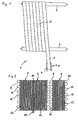
- device 1 has two spaced rollers 2, 3, which have parallel axes of rotation and are driven in the same direction.
- a supply roll 4 on which a plastic net 5 wound.
- the plastic net strip 5 is withdrawn when driving the rollers 2, 3 and winds on the two Rolls 2, 3 on.
- the supply roll 4 is moved in the direction of the arrow A, that is parallel to the axes of rotation of the rollers 2, 3.
- the plastic net strip 5 is spirally wound to the right progressively on the rollers 2, 3.
- the feed of the supply roll 4 in the direction of the arrow A is dimensioned so that the plastic net strip 5 comes to lie with the adjacent edges abutting each other. So that no tilting occur, the supply roll 4 is inclined accordingly.
- the winding process is continued until an oval tube is produced by means of the plastic net strip 5, the width of which corresponds approximately to the width of the machine felt to be produced before thermosetting.
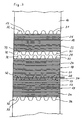
- FIG. 2 In the enlargement according to FIG. 2 are three partial webs 6, 7, 8 of the plastic mesh 5 shown. It can be seen that the plastic net strip 5-and thus the partial webs 6, 7, 8-have complementary wave-shaped courses at both longitudinal edges 9, 10, so that projections alternately-designated 11 by way of example-and complementary recesses-by way of example denoted by 12 arise.
- the projections 11 and recesses 12 mesh with each other like a tooth, wherein the projections 11 fill the recesses 12 over the entire surface.
- the partial web 8 is shown spaced from the partial web 7.
- FIG. 2 how out FIG. 2 can also be seen (and in FIG. 1 not shown), are on the plastic mesh 5 in the longitudinal direction extending longitudinal threads - exemplified by 13 - applied in parallel and at equal distances from each other, the longitudinal edges 9, 10, however, are left threadless.
- the longitudinal threads 13 are made of a thermoplastic material and are provided with an additive that makes them absorptive for laser energy.
- the longitudinal threads 13 are welded by the action of a transverse to them back and forth laser beam at points with the plastic mesh 5.
- the connection can be made even before winding the plastic mesh 5 on the supply roll 4 in a corresponding device. In this case, there is no pure plastic net strip 5 on the supply roll 4, but a combination of plastic net strip 5 and longitudinal threads 13 fastened thereto.
- longitudinal edges 9, 10 and the projections 11 On the longitudinal edges 9, 10 and the projections 11, three further longitudinal threads - exemplified by 14 - applied. They are similar to the longitudinal threads 13 and thus absorbent for laser energy. They are as well as the longitudinal threads 13 selectively heated to a melting temperature with a laser beam and thereby connect to the projections 11 of the plastic mesh tape 5. As a result, the longitudinal edges 9, 10 and thus the partial webs 6, 7, 8 are interconnected.
- the longitudinal threads 14 on the longitudinal edges 9, 10 have the same distances from one another and to the adjacent longitudinal threads 13, so that the thread density in the region of the longitudinal edges 9, 10 corresponds to that in the remaining area.
- the longitudinal threads 14 are applied to the longitudinal edges 9, 10 after application of the longitudinal threads 13 between the longitudinal edges 9, 10.
- a reverse order is selected, ie first the connection of the partial webs 6, 7, 8 by means of longitudinal threads 4 produced and then the remaining longitudinal threads 13 are applied.
- This can be done in each case in separate devices, which cause the laying of the longitudinal threads 13, 14 on the one hand and the fastening by means of a laser on the other.
- this device between the rollers 2, 3 is arranged and at the same time the longitudinal threads 13, 14 are placed next to each other and fixed. In this case, however, it is necessary that the two rollers 2, 3 are moved counter to the direction of the arrow A and the supply roll 4 is held stationary.
- FIG. 3 shows - in part - approximately in the scale according to FIG. 1 , but significantly opposite FIG. 2 reduced, a flat tube 16, which produced thereby has been that on the device 1 according to FIG. 1 finished hose is compressed after removal from the rollers 2, 3, so that the inner sides of the hose formed by the plastic mesh 5 come into mutual contact.
- the flat tube 16 has the length and width of the finished machine felt, but with a shrinkage to be taken into account during the subsequent heat-setting oversize.
- the here actually visible longitudinal threads 13, 14 are not shown.
- carrier module sections 17, 18, 19 are placed on the top of the flat tube 16 carrier module sections 17, 18, 19 .
- These carrier module sections 17, 18, 19 are constructed in the same way as the combination of plastic net strip 5 and longitudinal threads 13, from which the tube on the device according to FIG. 1 has been produced. They each consist of a plastic net strip 20, 21, 22, are applied to the transverse threads - for example, each with 23, 24, 25 - applied.
- the transverse threads 23, 24, 25 are similar to the longitudinal threads 13, 14 on the plastic mesh 5 (in FIG. 3 omitted) and are therefore also in the same way by means of a laser beam to the plastic mesh belt 20, 21, 22 attached. They each have the same distance from each other.
- the carrier module sections 17, 18, 19 are with the transverse threads 23, 24, 25 at the bottom placed on the flat tube 16, so that the transverse threads 23, 24, 25 contact the longitudinal threads 13, 14 have.
- the carrier module sections 17, 18, 19 have transverse edges 26 to 31, which are left free of transverse threads 23, 24, 25. They are in the same manner as the longitudinal edges 9, 10 of the plastic net 5 with successive projections - exemplified by 32 - and with complementary recesses - exemplified by 33 - provided. At the upper transverse edge 27 of the lower carrier module section 17 of the lower transverse edge 28 of the central carrier module section 18 is set so that their projections 32 and recesses 33 engage in a tooth-like manner. About the protrusions 32 are three transverse threads - exemplified by 34 - placed and attached to them. About the transverse threads 34, the two carrier module sections 17, 18 are interconnected. The attachment can also be done here by means of a laser beam.
- the upper carrier module section 19 is indeed placed on the flat tube 16.
- the upper carrier module section 19 must still be displaced so far toward the central carrier module section 18 that the projections 32 at the lower transverse edge 30 in the recesses 33 on the upper transverse edge 29 of the central carrier module section 18 in the same ways border between Carrier module sections 17, 18.
- three more transverse threads can be placed and connected to the projections 32.
- further carrier module sections are successively applied to the respectively preceding carrier module section and in each case connected thereto until the flat tube 16 on one side is completely covered by carrier module sections 17, 18, 19.
- any number of further carrier module sections can be constructed in principle. Of course, it is also possible to do this on the other flat side of the flat tube 16.
- FIG. 4 represents an analog representation of FIG. 2 but the manufacturing process is different.
- the same reference numbers are used for the same parts.
- partial webs 6, 7, 8 of the plastic mesh 5 are three partial webs 6, 7, 8 of the plastic mesh 5 partially shown.
- the partial webs 6, 7, 8 each have at both longitudinal edges 9, 10 complementary wave-shaped projections 11 made of plastic net strip 5 and complementary recesses 12.
- the projections 11 and recesses 12 already meshing with each other, while this in the partial web 8 with respect to the partial web 7 is not yet the case.
- plastic net strip 5 and thus on the partial webs 6, 7 extend longitudinally in longitudinal direction longitudinal threads - exemplified by 13 - parallel and in the same Distances to each other. They are welded by the action of a transverse reciprocating laser beam punctually with the plastic mesh 5.
- the application of the longitudinal threads 13, 14 on the plastic net 5 can be done before the winding of the provided with the longitudinal threads 13, 14 plastic net strip on the supply roll 4 in a corresponding device. However, it is also possible to apply the longitudinal threads 13, 14 only during or after the unwinding of the plastic net strip 5 from the supply roll 4 and then to place the partial webs 6, 7, 8 in such a way, the projections 11 mesh with one another in the recesses 12 in the manner of a tooth.
- the longitudinal threads 14 complement each other by the complete engagement of the projections 11 and recesses 12 such that the thread density in this area is equal to the thread density of the longitudinal threads 13 in the remaining area and in this way uniform L jossfadengelege arises (the fact that the already juxtaposed partial webs 6, 7 in the region of the projections 11 and recesses 12 are covered only by three longitudinal threads 14, while on the projections 11 and recesses 12 of the two not contiguous partial webs 7, 8 in total four longitudinal threads 14 extend, based only on a graphical inaccuracy).
- the longitudinal threads 14 are connected at the longitudinal edge 9 with the projections 11 at the longitudinal edge 10 by the action of a laser beam. Conversely, the longitudinal threads 14 are also connected at the longitudinal edge 10 with the projections on the adjacent longitudinal edge 9 by means of lasers.
- the type of connection of the longitudinal edges 9, 10 described above can also in the connection of the carrier module sections 17, 18, 19 according to FIG. 3 be applied accordingly.
- the carrier module sections 17, 18, 19 are then not only provided with the transverse threads 23, 24, 25, but additionally - and applied simultaneously with the transverse threads 23, 24, 25 - with transverse threads 34, which are over half the height of the projections 32 and Recesses 33 extend. Only then, the carrier module sections 17, 18, 19 are successively placed against each other and how the partial webs 6,7, 8 connected together in the manner described above.
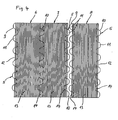
- FIG. 5 shows, created by the flattening of the on the device 1 according to FIG. 1 manufactured hose a machine felt 35 with transversely to the longitudinal threads 13, 14 extending end edges 36, 37, in the region of the longitudinal threads 13, 14 are bent by 180 °.
- the longitudinal threads 13, 14 are also covered in this area by the previously applied nonwoven layer 38 first like a matrix.
- the longitudinal threads 13, 14 are freed from fibrous material of the nonwoven layer 38 in this area, so that longitudinal thread loops projecting from the end edges 36, 37 - by way of example with 39 , 40 denotes - exposed.
- the longitudinal thread loops 39, 40 each form along the end edges 36, 37 extending channels 41, 42nd
Priority Applications (5)
| Application Number | Priority Date | Filing Date | Title |
|---|---|---|---|
| DE200750007083 DE502007007083D1 (de) | 2007-12-04 | 2007-12-04 | Verfahren zur Herstellung eines Maschinenfilzes sowie Maschinenfilz |
| AT07023459T ATE507348T1 (de) | 2007-12-04 | 2007-12-04 | Verfahren zur herstellung eines maschinenfilzes sowie maschinenfilz |
| EP20070023459 EP2067896B1 (fr) | 2007-12-04 | 2007-12-04 | Procédé destiné à la fabrication d'un feutre de machine, ainsi que feutre de machine |
| CN2008101788810A CN101451291B (zh) | 2007-12-04 | 2008-12-04 | 用于制造机制毡的方法以及机制毡 |
| US12/328,032 US8083898B2 (en) | 2007-12-04 | 2008-12-04 | Method for manufacturing a machine felt, and machine felt |
Applications Claiming Priority (1)
| Application Number | Priority Date | Filing Date | Title |
|---|---|---|---|
| EP20070023459 EP2067896B1 (fr) | 2007-12-04 | 2007-12-04 | Procédé destiné à la fabrication d'un feutre de machine, ainsi que feutre de machine |
Publications (2)
| Publication Number | Publication Date |
|---|---|
| EP2067896A1 true EP2067896A1 (fr) | 2009-06-10 |
| EP2067896B1 EP2067896B1 (fr) | 2011-04-27 |
Family
ID=39323693
Family Applications (1)
| Application Number | Title | Priority Date | Filing Date |
|---|---|---|---|
| EP20070023459 Active EP2067896B1 (fr) | 2007-12-04 | 2007-12-04 | Procédé destiné à la fabrication d'un feutre de machine, ainsi que feutre de machine |
Country Status (5)
| Country | Link |
|---|---|
| US (1) | US8083898B2 (fr) |
| EP (1) | EP2067896B1 (fr) |
| CN (1) | CN101451291B (fr) |
| AT (1) | ATE507348T1 (fr) |
| DE (1) | DE502007007083D1 (fr) |
Cited By (1)
| Publication number | Priority date | Publication date | Assignee | Title |
|---|---|---|---|---|
| EP2128335A1 (fr) * | 2008-05-28 | 2009-12-02 | Voith Patent GmbH | Procédé de fabrication d'une bande de feutre |
Families Citing this family (11)
| Publication number | Priority date | Publication date | Assignee | Title |
|---|---|---|---|---|
| GB2469651A (en) | 2009-04-21 | 2010-10-27 | Allan Richard Manninen | Seaming device for an industrial fabric |
| US8353252B1 (en) * | 2011-12-05 | 2013-01-15 | Voith Patent Gmbh | Process for preparing a seam area for a PMC base fabric |
| CN102586992B (zh) * | 2012-02-13 | 2013-07-03 | 东莞百宏实业有限公司 | 一种绳带复合织物及其制造方法和编织系统 |
| CN103841760A (zh) * | 2012-11-21 | 2014-06-04 | 欧普照明股份有限公司 | 一种可负载led光源的印刷电路板 |
| CN105358763B (zh) * | 2013-06-21 | 2018-04-06 | 福伊特专利有限公司 | 绷网及其制造方法 |
| US11098450B2 (en) | 2017-10-27 | 2021-08-24 | Albany International Corp. | Methods for making improved cellulosic products using novel press felts and products made therefrom |
| EP3722471A1 (fr) * | 2019-04-10 | 2020-10-14 | Textilma AG | Procédé de fabrication de bandes de tissus coupées à froid |
| WO2020237135A1 (fr) * | 2019-05-22 | 2020-11-26 | First Quality Tissue Se, Llc | Tissu de base tissé avec des fils en sens machine et en sens travers absorbant l'énergie laser et produit de tissu fabriqué à l'aide de celui-ci |
| CN114829271A (zh) * | 2019-12-18 | 2022-07-29 | 雀巢产品有限公司 | 具有突片的容器 |
| CN114801355B (zh) * | 2022-04-11 | 2023-12-15 | 武汉纺织大学 | 高复合强度多层隔热材料及应用 |
| CN114687037B (zh) * | 2022-04-11 | 2023-05-26 | 武汉纺织大学 | 易缝合的多层复合编织体及其应用 |
Citations (16)
| Publication number | Priority date | Publication date | Assignee | Title |
|---|---|---|---|---|
| US3767353A (en) | 1969-11-10 | 1973-10-23 | Conwed Corp | Apparatus for the extrusion of plastic net and net like structures |
| US3917889A (en) | 1971-10-18 | 1975-11-04 | Conwed Corp | Extruded tubular net products |
| US4123491A (en) | 1976-01-29 | 1978-10-31 | Conwed Corporation | Process for manufacturing high strand count plastic net |
| EP0307182A1 (fr) | 1987-09-09 | 1989-03-15 | ASTEN GROUP INC. (a Delaware corporation) | Feutre de presse humide non tissée et son procédé de fabrication |
| US5015220A (en) | 1988-08-03 | 1991-05-14 | Tamfelt, Inc. | Seam for work fabric and method of manufacture thereof |
| EP0464258A1 (fr) | 1990-06-13 | 1992-01-08 | Thomas Josef Heimbach GmbH & Co. | Feutre, en particulier pour machine à papier et son procédé de fabrication |
| GB2254287A (en) | 1991-04-05 | 1992-10-07 | Scapa Group Plc | Edge jointing of fabrics |
| WO1992017643A1 (fr) | 1991-04-05 | 1992-10-15 | Scapa Group Plc | Habillage pour machines a papier |
| EP0285376B1 (fr) | 1987-03-31 | 1993-01-27 | Leonard Robert Lefkowitz | Etoffe non tissée et son procédé de fabrication |
| US5360656A (en) | 1990-12-17 | 1994-11-01 | Albany International Corp. | Press felt and method of manufacturing it |
| WO1998056982A1 (fr) | 1997-06-12 | 1998-12-17 | Scapa Group Plc | Materiaux d'habillage de machine a fabriquer du papier |
| EP0947623A1 (fr) | 1998-04-02 | 1999-10-06 | Thomas Josef Heimbach Gesellschaft mit beschränkter Haftung & Co. | Bande textile, procédé pour la fabrication et appareil |
| EP0947627A1 (fr) | 1998-04-01 | 1999-10-06 | Thomas Josef Heimbach GmbH & Co. | Feutre pour papeterie et son procédé de fabrication |
| EP1045066A2 (fr) * | 1999-04-12 | 2000-10-18 | Albany International Corp. | Procédé pour raccorder des produits non-tissés en maille |
| EP1209283A1 (fr) | 2000-11-23 | 2002-05-29 | Thomas Josef Heimbach Gesellschaft mit beschränkter Haftung | Tissu, en particulier un tissu pour machine à papier |
| EP1837440A1 (fr) | 2006-03-21 | 2007-09-26 | Helmbach GmbH & Co.KG | Procédé destiné à la fabrication d'une bande de feutre tout comme bande de feutre |
Family Cites Families (5)
| Publication number | Priority date | Publication date | Assignee | Title |
|---|---|---|---|---|
| US5268076A (en) | 1990-06-13 | 1993-12-07 | Thomas Josef Heimbach Gmbh & Co. | Spiral wound papermaking-machine felt |
| US5864931A (en) | 1991-05-23 | 1999-02-02 | Thomas Josef Heimbach Gmbh & Co. | Felt, in particular a papermaking-machine felt, and method for its manufacture |
| EP1359251B1 (fr) * | 2002-04-25 | 2005-06-29 | Thomas Josef Heimbach Gesellschaft mit beschränkter Haftung & Co. | Toile de séchage et procédé de sa production |
| CN101041922B (zh) * | 2006-03-21 | 2010-06-09 | 亨巴赫有限公司&两合公司 | 制造毡带的方法和毡带 |
| ES2372111T3 (es) * | 2006-03-21 | 2012-01-16 | Heimbach Gmbh & Co. Kg | Procedimiento para fabricar una cinta de fieltro y cinta de fieltro. |
-
2007
- 2007-12-04 EP EP20070023459 patent/EP2067896B1/fr active Active
- 2007-12-04 AT AT07023459T patent/ATE507348T1/de active
- 2007-12-04 DE DE200750007083 patent/DE502007007083D1/de active Active
-
2008
- 2008-12-04 CN CN2008101788810A patent/CN101451291B/zh active Active
- 2008-12-04 US US12/328,032 patent/US8083898B2/en active Active
Patent Citations (16)
| Publication number | Priority date | Publication date | Assignee | Title |
|---|---|---|---|---|
| US3767353A (en) | 1969-11-10 | 1973-10-23 | Conwed Corp | Apparatus for the extrusion of plastic net and net like structures |
| US3917889A (en) | 1971-10-18 | 1975-11-04 | Conwed Corp | Extruded tubular net products |
| US4123491A (en) | 1976-01-29 | 1978-10-31 | Conwed Corporation | Process for manufacturing high strand count plastic net |
| EP0285376B1 (fr) | 1987-03-31 | 1993-01-27 | Leonard Robert Lefkowitz | Etoffe non tissée et son procédé de fabrication |
| EP0307182A1 (fr) | 1987-09-09 | 1989-03-15 | ASTEN GROUP INC. (a Delaware corporation) | Feutre de presse humide non tissée et son procédé de fabrication |
| US5015220A (en) | 1988-08-03 | 1991-05-14 | Tamfelt, Inc. | Seam for work fabric and method of manufacture thereof |
| EP0464258A1 (fr) | 1990-06-13 | 1992-01-08 | Thomas Josef Heimbach GmbH & Co. | Feutre, en particulier pour machine à papier et son procédé de fabrication |
| US5360656A (en) | 1990-12-17 | 1994-11-01 | Albany International Corp. | Press felt and method of manufacturing it |
| GB2254287A (en) | 1991-04-05 | 1992-10-07 | Scapa Group Plc | Edge jointing of fabrics |
| WO1992017643A1 (fr) | 1991-04-05 | 1992-10-15 | Scapa Group Plc | Habillage pour machines a papier |
| WO1998056982A1 (fr) | 1997-06-12 | 1998-12-17 | Scapa Group Plc | Materiaux d'habillage de machine a fabriquer du papier |
| EP0947627A1 (fr) | 1998-04-01 | 1999-10-06 | Thomas Josef Heimbach GmbH & Co. | Feutre pour papeterie et son procédé de fabrication |
| EP0947623A1 (fr) | 1998-04-02 | 1999-10-06 | Thomas Josef Heimbach Gesellschaft mit beschränkter Haftung & Co. | Bande textile, procédé pour la fabrication et appareil |
| EP1045066A2 (fr) * | 1999-04-12 | 2000-10-18 | Albany International Corp. | Procédé pour raccorder des produits non-tissés en maille |
| EP1209283A1 (fr) | 2000-11-23 | 2002-05-29 | Thomas Josef Heimbach Gesellschaft mit beschränkter Haftung | Tissu, en particulier un tissu pour machine à papier |
| EP1837440A1 (fr) | 2006-03-21 | 2007-09-26 | Helmbach GmbH & Co.KG | Procédé destiné à la fabrication d'une bande de feutre tout comme bande de feutre |
Cited By (1)
| Publication number | Priority date | Publication date | Assignee | Title |
|---|---|---|---|---|
| EP2128335A1 (fr) * | 2008-05-28 | 2009-12-02 | Voith Patent GmbH | Procédé de fabrication d'une bande de feutre |
Also Published As
| Publication number | Publication date |
|---|---|
| CN101451291A (zh) | 2009-06-10 |
| US20090139600A1 (en) | 2009-06-04 |
| EP2067896B1 (fr) | 2011-04-27 |
| ATE507348T1 (de) | 2011-05-15 |
| DE502007007083D1 (de) | 2011-06-09 |
| CN101451291B (zh) | 2011-03-30 |
| US8083898B2 (en) | 2011-12-27 |
Similar Documents
| Publication | Publication Date | Title |
|---|---|---|
| EP2067896B1 (fr) | Procédé destiné à la fabrication d'un feutre de machine, ainsi que feutre de machine | |
| EP0947623B1 (fr) | Bande textile, procédé pour la fabrication et appareil | |
| EP1837440B1 (fr) | Procédé destiné à la fabrication d'une bande de feutre et une bande de feutre | |
| DE60033976T2 (de) | Verfahren zum Verbinden von Gittervliesen | |
| EP2358940B1 (fr) | Feutre de presse et son procédé de réalisation | |
| EP0261488B1 (fr) | Feutre pour papeterie et son procédé de fabrication | |
| DE60201576T2 (de) | Mehrschichtstruktur für papiermaschinenbespannung | |
| EP1209283B1 (fr) | Tissu, en particulier une toile pour machine à papier | |
| EP0947627B2 (fr) | Feutre pour papeterie et son procédé de fabrication | |
| EP2358939B1 (fr) | Toile de machine à papier et son procédé de réalisation | |
| EP2128335B1 (fr) | Procédé de fabrication d'une bande de feutre | |
| EP2107159A1 (fr) | Feutre de presse et son procédé de fabrication | |
| DE202006004624U1 (de) | Filzband, insbesondere Papiermaschinenfilz | |
| EP4137636A1 (fr) | Bande textile et utilisation d'une telle bande | |
| DE102007000579A1 (de) | Papiermaschinenbespannungen, insbesondere für Pressfilze, und Verfahren zu deren Herstellung | |
| DE19823272A1 (de) | Verfahren zur Herstellung eines Vliesstoffes mit velourartiger Oberfläche | |
| DE102008043855A1 (de) | Papiermaschinenbespannung und Verfahren zu deren Herstellung | |
| EP1452639A1 (fr) | Habillage de machine à papier | |
| WO2012140046A1 (fr) | Procédé de production d'un module, en particulier d'un module sans fin, pour l'habillage d'une machine à papier, et module sans fin associé | |
| DE202009010898U1 (de) | Papiermaschinenbespannung | |
| DE102008000123A1 (de) | Papiermaschinenbespannung mit Scharniernaht | |
| DE202022101466U1 (de) | Industrielles Textil und Verwendung eines solchen | |
| WO2012139901A1 (fr) | Procédé de production d'un module sans fin pour l'habillage d'une machine à papier et module sans fin pour l'habillage d'une machine à papier | |
| DE202006019681U1 (de) | Textilbahn | |
| EP2697427A1 (fr) | Procédé de production d'un module sans fin, pour l'habillage d'une machine à papier, et module sans fin associé |
Legal Events
| Date | Code | Title | Description |
|---|---|---|---|
| PUAI | Public reference made under article 153(3) epc to a published international application that has entered the european phase |
Free format text: ORIGINAL CODE: 0009012 |
|
| 17P | Request for examination filed |
Effective date: 20080612 |
|
| AK | Designated contracting states |
Kind code of ref document: A1 Designated state(s): AT BE BG CH CY CZ DE DK EE ES FI FR GB GR HU IE IS IT LI LT LU LV MC MT NL PL PT RO SE SI SK TR |
|
| AX | Request for extension of the european patent |
Extension state: AL BA HR MK RS |
|
| AKX | Designation fees paid |
Designated state(s): AT BE BG CH CY CZ DE DK EE ES FI FR GB GR HU IE IS IT LI LT LU LV MC MT NL PL PT RO SE SI SK TR |
|
| GRAP | Despatch of communication of intention to grant a patent |
Free format text: ORIGINAL CODE: EPIDOSNIGR1 |
|
| GRAS | Grant fee paid |
Free format text: ORIGINAL CODE: EPIDOSNIGR3 |
|
| GRAA | (expected) grant |
Free format text: ORIGINAL CODE: 0009210 |
|
| AK | Designated contracting states |
Kind code of ref document: B1 Designated state(s): AT BE BG CH CY CZ DE DK EE ES FI FR GB GR HU IE IS IT LI LT LU LV MC MT NL PL PT RO SE SI SK TR |
|
| REG | Reference to a national code |
Ref country code: GB Ref legal event code: FG4D Free format text: NOT ENGLISH |
|
| REG | Reference to a national code |
Ref country code: CH Ref legal event code: EP |
|
| REG | Reference to a national code |
Ref country code: SE Ref legal event code: TRGR |
|
| REG | Reference to a national code |
Ref country code: IE Ref legal event code: FG4D Free format text: LANGUAGE OF EP DOCUMENT: GERMAN |
|
| REF | Corresponds to: |
Ref document number: 502007007083 Country of ref document: DE Date of ref document: 20110609 Kind code of ref document: P |
|
| REG | Reference to a national code |
Ref country code: DE Ref legal event code: R096 Ref document number: 502007007083 Country of ref document: DE Effective date: 20110609 |
|
| REG | Reference to a national code |
Ref country code: NL Ref legal event code: T3 |
|
| LTIE | Lt: invalidation of european patent or patent extension |
Effective date: 20110427 |
|
| PG25 | Lapsed in a contracting state [announced via postgrant information from national office to epo] |
Ref country code: PT Free format text: LAPSE BECAUSE OF FAILURE TO SUBMIT A TRANSLATION OF THE DESCRIPTION OR TO PAY THE FEE WITHIN THE PRESCRIBED TIME-LIMIT Effective date: 20110829 Ref country code: LT Free format text: LAPSE BECAUSE OF FAILURE TO SUBMIT A TRANSLATION OF THE DESCRIPTION OR TO PAY THE FEE WITHIN THE PRESCRIBED TIME-LIMIT Effective date: 20110427 |
|
| REG | Reference to a national code |
Ref country code: IE Ref legal event code: FD4D |
|
| PG25 | Lapsed in a contracting state [announced via postgrant information from national office to epo] |
Ref country code: IS Free format text: LAPSE BECAUSE OF FAILURE TO SUBMIT A TRANSLATION OF THE DESCRIPTION OR TO PAY THE FEE WITHIN THE PRESCRIBED TIME-LIMIT Effective date: 20110827 Ref country code: LV Free format text: LAPSE BECAUSE OF FAILURE TO SUBMIT A TRANSLATION OF THE DESCRIPTION OR TO PAY THE FEE WITHIN THE PRESCRIBED TIME-LIMIT Effective date: 20110427 Ref country code: CY Free format text: LAPSE BECAUSE OF FAILURE TO SUBMIT A TRANSLATION OF THE DESCRIPTION OR TO PAY THE FEE WITHIN THE PRESCRIBED TIME-LIMIT Effective date: 20110427 Ref country code: SI Free format text: LAPSE BECAUSE OF FAILURE TO SUBMIT A TRANSLATION OF THE DESCRIPTION OR TO PAY THE FEE WITHIN THE PRESCRIBED TIME-LIMIT Effective date: 20110427 Ref country code: GR Free format text: LAPSE BECAUSE OF FAILURE TO SUBMIT A TRANSLATION OF THE DESCRIPTION OR TO PAY THE FEE WITHIN THE PRESCRIBED TIME-LIMIT Effective date: 20110728 Ref country code: ES Free format text: LAPSE BECAUSE OF FAILURE TO SUBMIT A TRANSLATION OF THE DESCRIPTION OR TO PAY THE FEE WITHIN THE PRESCRIBED TIME-LIMIT Effective date: 20110807 |
|
| PG25 | Lapsed in a contracting state [announced via postgrant information from national office to epo] |
Ref country code: EE Free format text: LAPSE BECAUSE OF FAILURE TO SUBMIT A TRANSLATION OF THE DESCRIPTION OR TO PAY THE FEE WITHIN THE PRESCRIBED TIME-LIMIT Effective date: 20110427 Ref country code: CZ Free format text: LAPSE BECAUSE OF FAILURE TO SUBMIT A TRANSLATION OF THE DESCRIPTION OR TO PAY THE FEE WITHIN THE PRESCRIBED TIME-LIMIT Effective date: 20110427 Ref country code: IE Free format text: LAPSE BECAUSE OF FAILURE TO SUBMIT A TRANSLATION OF THE DESCRIPTION OR TO PAY THE FEE WITHIN THE PRESCRIBED TIME-LIMIT Effective date: 20110427 |
|
| PG25 | Lapsed in a contracting state [announced via postgrant information from national office to epo] |
Ref country code: PL Free format text: LAPSE BECAUSE OF FAILURE TO SUBMIT A TRANSLATION OF THE DESCRIPTION OR TO PAY THE FEE WITHIN THE PRESCRIBED TIME-LIMIT Effective date: 20110427 Ref country code: RO Free format text: LAPSE BECAUSE OF FAILURE TO SUBMIT A TRANSLATION OF THE DESCRIPTION OR TO PAY THE FEE WITHIN THE PRESCRIBED TIME-LIMIT Effective date: 20110427 Ref country code: DK Free format text: LAPSE BECAUSE OF FAILURE TO SUBMIT A TRANSLATION OF THE DESCRIPTION OR TO PAY THE FEE WITHIN THE PRESCRIBED TIME-LIMIT Effective date: 20110427 Ref country code: SK Free format text: LAPSE BECAUSE OF FAILURE TO SUBMIT A TRANSLATION OF THE DESCRIPTION OR TO PAY THE FEE WITHIN THE PRESCRIBED TIME-LIMIT Effective date: 20110427 |
|
| PLBE | No opposition filed within time limit |
Free format text: ORIGINAL CODE: 0009261 |
|
| STAA | Information on the status of an ep patent application or granted ep patent |
Free format text: STATUS: NO OPPOSITION FILED WITHIN TIME LIMIT |
|
| 26N | No opposition filed |
Effective date: 20120130 |
|
| REG | Reference to a national code |
Ref country code: DE Ref legal event code: R097 Ref document number: 502007007083 Country of ref document: DE Effective date: 20120130 |
|
| BERE | Be: lapsed |
Owner name: HEIMBACH G.M.B.H. & CO.KG Effective date: 20111231 |
|
| PG25 | Lapsed in a contracting state [announced via postgrant information from national office to epo] |
Ref country code: MC Free format text: LAPSE BECAUSE OF NON-PAYMENT OF DUE FEES Effective date: 20111231 |
|
| PG25 | Lapsed in a contracting state [announced via postgrant information from national office to epo] |
Ref country code: BE Free format text: LAPSE BECAUSE OF NON-PAYMENT OF DUE FEES Effective date: 20111231 |
|
| PG25 | Lapsed in a contracting state [announced via postgrant information from national office to epo] |
Ref country code: MT Free format text: LAPSE BECAUSE OF FAILURE TO SUBMIT A TRANSLATION OF THE DESCRIPTION OR TO PAY THE FEE WITHIN THE PRESCRIBED TIME-LIMIT Effective date: 20110427 |
|
| PG25 | Lapsed in a contracting state [announced via postgrant information from national office to epo] |
Ref country code: LU Free format text: LAPSE BECAUSE OF NON-PAYMENT OF DUE FEES Effective date: 20111204 |
|
| PG25 | Lapsed in a contracting state [announced via postgrant information from national office to epo] |
Ref country code: BG Free format text: LAPSE BECAUSE OF FAILURE TO SUBMIT A TRANSLATION OF THE DESCRIPTION OR TO PAY THE FEE WITHIN THE PRESCRIBED TIME-LIMIT Effective date: 20110727 |
|
| PG25 | Lapsed in a contracting state [announced via postgrant information from national office to epo] |
Ref country code: TR Free format text: LAPSE BECAUSE OF FAILURE TO SUBMIT A TRANSLATION OF THE DESCRIPTION OR TO PAY THE FEE WITHIN THE PRESCRIBED TIME-LIMIT Effective date: 20110427 |
|
| PG25 | Lapsed in a contracting state [announced via postgrant information from national office to epo] |
Ref country code: HU Free format text: LAPSE BECAUSE OF FAILURE TO SUBMIT A TRANSLATION OF THE DESCRIPTION OR TO PAY THE FEE WITHIN THE PRESCRIBED TIME-LIMIT Effective date: 20110427 |
|
| REG | Reference to a national code |
Ref country code: FR Ref legal event code: PLFP Year of fee payment: 9 |
|
| REG | Reference to a national code |
Ref country code: FR Ref legal event code: PLFP Year of fee payment: 10 |
|
| PGFP | Annual fee paid to national office [announced via postgrant information from national office to epo] |
Ref country code: GB Payment date: 20161222 Year of fee payment: 10 Ref country code: NL Payment date: 20161123 Year of fee payment: 10 |
|
| PGFP | Annual fee paid to national office [announced via postgrant information from national office to epo] |
Ref country code: IT Payment date: 20161220 Year of fee payment: 10 |
|
| REG | Reference to a national code |
Ref country code: FR Ref legal event code: PLFP Year of fee payment: 11 |
|
| REG | Reference to a national code |
Ref country code: NL Ref legal event code: MM Effective date: 20180101 |
|
| GBPC | Gb: european patent ceased through non-payment of renewal fee |
Effective date: 20171204 |
|
| PG25 | Lapsed in a contracting state [announced via postgrant information from national office to epo] |
Ref country code: NL Free format text: LAPSE BECAUSE OF NON-PAYMENT OF DUE FEES Effective date: 20180101 |
|
| PG25 | Lapsed in a contracting state [announced via postgrant information from national office to epo] |
Ref country code: IT Free format text: LAPSE BECAUSE OF NON-PAYMENT OF DUE FEES Effective date: 20171204 |
|
| REG | Reference to a national code |
Ref country code: FR Ref legal event code: PLFP Year of fee payment: 12 |
|
| PG25 | Lapsed in a contracting state [announced via postgrant information from national office to epo] |
Ref country code: GB Free format text: LAPSE BECAUSE OF NON-PAYMENT OF DUE FEES Effective date: 20171204 |
|
| PGFP | Annual fee paid to national office [announced via postgrant information from national office to epo] |
Ref country code: CH Payment date: 20230103 Year of fee payment: 16 |
|
| PGFP | Annual fee paid to national office [announced via postgrant information from national office to epo] |
Ref country code: SE Payment date: 20231219 Year of fee payment: 17 Ref country code: FR Payment date: 20231127 Year of fee payment: 17 Ref country code: FI Payment date: 20231218 Year of fee payment: 17 Ref country code: DE Payment date: 20231127 Year of fee payment: 17 Ref country code: AT Payment date: 20231129 Year of fee payment: 17 |
|
| PGFP | Annual fee paid to national office [announced via postgrant information from national office to epo] |
Ref country code: CH Payment date: 20240109 Year of fee payment: 17 |