EP0464258A1 - Feutre, en particulier pour machine à papier et son procédé de fabrication - Google Patents
Feutre, en particulier pour machine à papier et son procédé de fabrication Download PDFInfo
- Publication number
- EP0464258A1 EP0464258A1 EP90124010A EP90124010A EP0464258A1 EP 0464258 A1 EP0464258 A1 EP 0464258A1 EP 90124010 A EP90124010 A EP 90124010A EP 90124010 A EP90124010 A EP 90124010A EP 0464258 A1 EP0464258 A1 EP 0464258A1
- Authority
- EP
- European Patent Office
- Prior art keywords
- web
- felt
- carrier
- strip
- carrier web
- Prior art date
- Legal status (The legal status is an assumption and is not a legal conclusion. Google has not performed a legal analysis and makes no representation as to the accuracy of the status listed.)
- Granted
Links
Images

Classifications
-
- D—TEXTILES; PAPER
- D21—PAPER-MAKING; PRODUCTION OF CELLULOSE
- D21F—PAPER-MAKING MACHINES; METHODS OF PRODUCING PAPER THEREON
- D21F7/00—Other details of machines for making continuous webs of paper
- D21F7/08—Felts
- D21F7/083—Multi-layer felts
-
- D—TEXTILES; PAPER
- D04—BRAIDING; LACE-MAKING; KNITTING; TRIMMINGS; NON-WOVEN FABRICS
- D04H—MAKING TEXTILE FABRICS, e.g. FROM FIBRES OR FILAMENTARY MATERIAL; FABRICS MADE BY SUCH PROCESSES OR APPARATUS, e.g. FELTS, NON-WOVEN FABRICS; COTTON-WOOL; WADDING ; NON-WOVEN FABRICS FROM STAPLE FIBRES, FILAMENTS OR YARNS, BONDED WITH AT LEAST ONE WEB-LIKE MATERIAL DURING THEIR CONSOLIDATION
- D04H13/00—Other non-woven fabrics
-
- D—TEXTILES; PAPER
- D04—BRAIDING; LACE-MAKING; KNITTING; TRIMMINGS; NON-WOVEN FABRICS
- D04H—MAKING TEXTILE FABRICS, e.g. FROM FIBRES OR FILAMENTARY MATERIAL; FABRICS MADE BY SUCH PROCESSES OR APPARATUS, e.g. FELTS, NON-WOVEN FABRICS; COTTON-WOOL; WADDING ; NON-WOVEN FABRICS FROM STAPLE FIBRES, FILAMENTS OR YARNS, BONDED WITH AT LEAST ONE WEB-LIKE MATERIAL DURING THEIR CONSOLIDATION
- D04H18/00—Needling machines
- D04H18/02—Needling machines with needles
Definitions
- the invention relates to a felt, in particular paper machine felt, primarily for the press section of a paper machine, with at least one carrier web and at least one fiber web attached to it and connected to it. It also relates to a method for producing such an endless felt. Such felts are primarily used for the transport of thin webs through devices for producing the same, a main area of application being the production of paper in paper machines.
- the known felts have at least one carrier web and at least one fiber web applied thereon.
- the carrier web - there may also be several carrier webs arranged one above the other with fiber webs in between - is designed in such a way that it gives the felt the structural strength in the longitudinal and transverse directions necessary for the intended purpose. It is therefore a matter of coherent webs, primarily fabrics being used. However, knitted fabrics, spunbonded nonwovens or bonded nonwoven fabrics reinforced in the transverse and longitudinal directions are also proposed.
- a fiber web is then placed at least on the surface of the carrier web and connected to the carrier web in order to achieve a smooth surface and to avoid damage to the web to be transported, for example a paper web.
- the structure of such a felt is also based on the fact that the best possible drainage is achieved by the felt.
- Such felts are still mainly produced in such a way that first the carrier web is produced in the width corresponding to the finished felt and only then is a fiber web extending over the full width placed on it and connected to the carrier web.
- the connection is made primarily by needling, but also by gluing.
- a carrier web is first produced in the width corresponding to the width of the finished felt and is drawn onto two transport rollers arranged at a distance from one another and stretched between them. Then a fibrous web strip, the width of which is less than that of the finished felt, is fed to the carrier web and fastened to it.
- the carrier web is then moved in the circumferential direction, a relative movement being generated between the fiber web strip to be fed and the carrier web transversely to its direction of rotation. Because of this relative movement, the fibrous web strip progressively winds onto the carrier web transversely to the direction of rotation.
- a fibrous web is thus gradually built up, which can also be constructed in multiple layers. At the same time, needling and thus a connection between the fiber web and the carrier web is carried out in this device.
- the feed device for the fibrous web strips is moved transversely to the transport rollers.
- the device according to DE-B-1 660 765 and EP-B-0 123 969 is used kinematically in reverse.
- the feed device is arranged in a stationary manner and the carrier web is accordingly shifted across on the transport rollers.
- grooves are incorporated in the transport rollers parallel to their longitudinal axes, in which grooves run transport chains which are provided with needles projecting into the carrier web. It is conceivable, albeit complex, to combine the two principles.
- the device can also be used for treatment and processing measures, such as flaming, needles, brushes or the like. Threads running at a distance from one another can also be applied to the felt to form longitudinal drainage channels.
- US-A-4 495 680 and US-A-4 594 756 are concerned with a device for producing the longitudinal thread structure known from US-A-3 097 413, wherein the longitudinal thread structure can subsequently be needled with a fibrous web, either in the device itself or in a conventional needle machine.
- felts of the generic type are still produced with carrier webs as webs connected in the transverse and longitudinal directions, in particular even when the nonwoven web in the form of nonwoven web strips is applied continuously in the circumferential direction, but progressively in a helical manner in the transverse direction.
- This is shown by the just published DE-A-39 37 651 and DE-A-39 37 652.
- the disadvantage must be accepted that the carrier web must first be made in the width corresponding to the finished felt, which is done in correspondingly wide machines , for example weaving or knitting machines, happens. Since paper machine felts in particular have large widths, expensive and mostly slow-working weaving machines must be used for this. Knitting machines are only available in limited widths anyway, so that knitted fabrics have so far only been used with narrow felts. In addition, the machines must be set up accordingly for each paper machine felt, since paper machine felts are not series products. This results in high production costs and little flexibility. In addition, their internal transport and installation in devices in which the fiber web is applied is cumbersome and complex.
- the invention has for its object to design a paper machine felt of the type mentioned so that it has improved running properties despite sufficient transverse stability and can be produced at significantly lower costs.
- a felt is provided for the first time in which the respective carrier web is composed of one or more carrier web strips, which extends essentially in the running direction of the felt, but is or are wound in a helical shape. It has been found to be surprising that even such a carrier web - in comparison to thread lay - gives sufficient transverse stability. This apparently has to do with the fact that the carrier web strips themselves have their own transverse stability and therefore do not tend to dodge or shift in the transverse direction. On the other hand, the transverse stability is effectively supported by the fact that the fibrous web is connected to the carrier web strips, in particular needled. Correspondingly, this felt can also be used in the case of high loads, such as those which occur especially in the press section of a paper machine, without its dimensional stability being impaired compared to the generic felts.
- a loom or knitting machine of a correspondingly small width is sufficient for producing the carrier web strip, regardless of the width of the finished felt.
- Such machines are not only inexpensive, they also work faster.
- the possibility is opened to produce very wide felts, such as those used in high-performance paper machines, with a carrier web from a knitted fabric.
- the carrier web strips can be produced in long lengths and thus without retrofitting the machines on supply rolls, which also results in a more economical and, moreover, more flexible production.
- the supply rolls are then called up and then a device, as it is in principle from the publications mentioned (DE-B-23 24 985, DE-A-39 37 652, DE-B-1 660 765 , EP-B-0 123 969) is supplied.
- the production of the felt composed of carrier web and fiber web can then take place in this device in one work step, which also contributes to the fact that the production costs are considerably lower compared to those of conventional felts.
- There are practically no limits to the width of the felt i.e. it is also possible to produce very wide felts regardless of the width and the structure of the respective web strip.
- no special measures are required to set this width, since the manufacturing process is simply terminated when the end width of the felt is reached.
- the carrier web or at least one carrier web is formed in several layers from a plurality of carrier web strips which are wound one above the other. This makes it possible to give the individual layers of the carrier web different properties by using appropriate carrier web strips. If this is not necessary, the carrier web or at least one carrier web can be formed from a carrier web strip which is wound over one another in multiple layers.
- the carrier web strip or at least one carrier web strip can be wound helically in such a way that the longitudinal edges of the respective carrier web strip lie against one another. This results in a particularly uniform carrier web structure across the width of the felt.
- the adjacent winding sections of the respective carrier web strip can also partially overlap. In this way, particularly good transverse stability is achieved, in particular if the overlapping sections are needled with the fiber web.
- At least one layer with overlapping carrier web strips and one layer with non-overlapping carrier web strips can also be combined with one another, the combination preferably being such that the longitudinal edges of the carrier web strips do not lie one above the other, i.e. run offset to each other.
- the felt according to the invention can be constructed practically as desired. Several carrier webs can be provided, which are separated by a fiber web. The felt can also have a fiber web on both sides and also have multi-layer fiber webs.
- the fibrous web or at least one fibrous web is formed from at least one fibrous web strip, the width of which is less than the felt and the or which progresses essentially in the running direction of the felt and in a spiral shape transversely thereto is or are wound.
- the fiber web or - in the case of several fiber webs - at least one fiber web - if not all - is constructed in the same way as the carrier web.
- This structure of the fiber web (s) has several advantages. On the one hand, the fiber web strip can be produced on a small machine of appropriate width and kept ready in the form of supply rolls. On the other hand, the subsequent production of the felt - if all fiber webs are built up accordingly - can be done in one machine and thus at particularly low cost.
- the or at least one of the fibrous web strips, from which a fibrous web adjacent to a carrier web is constructed is wound helically so that the fibrous web strip is connected to two adjacent winding sections of the carrier web strip.
- This arrangement supports the transverse stability of the felt.
- at least one fiber web forming one side of the felt it may be expedient for at least one fiber web forming one side of the felt to be continuous is formed, ie is not made up of a fibrous web strip.
- the method according to the invention first requires the production of a material web to which the carrier web strip is attached and which can be moved in the circumferential direction.
- This material web can be designed differently depending on the desired structure of the felt. It is thus possible to first separately produce a fibrous web the width of the finished felt, for example on a needle machine, and then to pull this fibrous web onto the device known in principle so that it can then be rotated in the direction of rotation. The - first - carrier web strip can then be attached to this fiber web.
- the material web is made as a material web strip with a width that is less than the width of the finished felt, and that the material web strip is removed again at the latest after the felt is finished.
- the carrier web strip but also several - can then be attached to this material web strip at the beginning of the carrier web construction.
- the material web strip can be, for example, a waste or scrap product of any structure.
- the material web can also be constructed in a combined manner, namely from a material web strip whose width is less than that of the finished felt, and from at least one fibrous web strip attached to it, the width or width of which is also or is less than that of the finished felt .
- the fiber web strip is or are constructed helically to form a fiber web in that it is or are continuously fed transversely to the direction of rotation when there is relative movement between the fiber web strip and the part of the fiber web that has already been built up.
- the material web consists of a material web strip which is to be removed again after completion and of a fiber web strip which is built up into a fiber web by helical winding.
- the carrier web strip is then fastened to it for the purpose of building up the carrier web, the fastening being able to take place with or directly to the connection of the fiber web strip to the material web strip or only after the fiber web has been completed.
- a felt consisting of a carrier web and an external fiber web is obtained in this way.
- fiber webs which are constructed from fiber web strips in the manner described, in order to allow the production process to run in one device.
- fiber web strips and carrier web strips run adjacent, they should be fed so that they are offset transversely to the circumferential direction in such a way that the fiber web strip comes to lie over two adjacent carrier web strips. This supports the cross stability of the felt.
- the feed can also proceed in such a way that a multi-layer carrier web and / or a multi-layer fiber web are built up, either by feeding several carrier web strips and / or fiber web strips, or by having a carrier web strip or fiber web strip through at least one-time reversal of the relative movement between carrier web strips or fibrous web strips and already built-up part of the felt is wound over one another transversely to the direction of rotation.
- carrier web strips and / or fiber web strips can take place in such a way that the longitudinal edges come to lie against one another or that the winding sections partially overlap.
- these two alternatives can also be combined with one another in terms of layers.
- At least one additional fiber web in the width of the finished felt is separately finished and then applied and fastened to the top and / or bottom of the built-up part of the felt.
- several carrier webs can be built up by helically winding up carrier web strips, a fiber web being built up between the carrier webs by helically winding up the fibrous web strip.
- a particularly effective and hardly disturbing the structure of the felt connection between the fibrous web and the carrier web is produced in a manner known per se by needling, the needling being carried out in strips even during the construction of the carrier web and / or the fibrous web by the device used for this purpose a corresponding needle device is assigned.
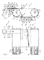
- the device (1) shown in Figures (1) and (2) has two transport rollers (2, 3) which have horizontal axes of rotation (4, 5) and are mounted at a horizontal distance from one another.
- the transport rollers (2, 3) have grooves, which are distributed over the lateral surfaces and run parallel to the axes of rotation (4, 5), for example with (6, 7), in which transport chains - for example with (8, 9) - are guided .
- the transport rollers (2, 3) rotate in the directions of arrows A.
- the device (1) has two feed devices (12, 13).
- a total of four supply rolls (14, 15, 16, 17) are rotatably mounted in the upper feed device (12) in the direction of the arrows, namely two adjacent upper supply rolls (14, 15) and two lower supply rolls also arranged side by side ( 16, 17).
- Each supply roll (14, 15, 16, 17) has an axis of rotation (18, 19, 20, 21), on each of which a web strip (22, 23, 24, 25) is wound.
- Guide rollers (26, 27, 28) ensure perfect guidance of the unwound web strips (22, 23, 24, 25).
- a carding device could also be provided, via which a nonwoven fabric can be fed.
- the second feed device (13) is arranged on the underside of the device.
- two supply rolls (29, 30) are mounted next to each other, which here too consist of the axes of rotation (31, 32) and the web strips (33, 34) wound on them.
- Guide rollers (35, 36) serve to support the unwound web strips (33, 34).
- the device (1) also has a needle machine (37), of which only the nail boards (38, 39, 40) are shown.
- the nail boards (38, 39, 40) are arranged one above the other and can be moved vertically.
- a needle board (38) is provided in the upper part of the device (1), while two counter-rotating needle boards (39, 40) are provided in the lower part.
- fibrous web strips or carrier web strips can be used as web strips (22, 23, 24, 25, 33, 34).
- the fibrous web strips then consist of a nonwoven fabric, the nonwoven fabric having different fiber orientations, fineness and fiber density, while the carrier web strips can have different structures, for example woven, knitted, spunbonded nonwoven, film and / or composite thread laid strips.
- a strip of material is first drawn onto the two transport rollers (2, 3), approximately at the level of the supply of the supply rolls (14, 15, 16, 17, 29, 30).
- This strip of material web can be, for example, a reject fabric strip.
- the individual web strips (22, 23, 24, 25, 33, 34) are then attached to this material web strip with their front ends.
- the two transport rollers (2, 3) and thus the material web strip are then set in motion in the circumferential direction, as a result of which the web strips (22, 23, 24, 25, 33, 34) are removed from the supply rolls (14, 15, 16, 17, 29, 30) are pulled off and come to rest on the material web strip.
- the needle machine (37) is put into operation, with the result that the individual web strips (22, 23, 24, 25, 33, 34) are needled together, i.e. the fibers of the fiber web strips penetrate into the carrier web strips.
- the transport chains (8, 9) With the rotation of the transport rollers (2, 3), the transport chains (8, 9) are set in motion in the directions of the arrows B. This has the consequence that the material web strip and thus also the part (41) of the felt already built on it are transported accordingly. Due to the relative movement between this part (41) of the felt and the web strips (22, 23, 24, 25, 33, 34), the latter are wound helically onto the transport rollers (2, 3) at a speed of the transport chains (8 , 9) corresponding slope.
- the web strips (22, 23, 24, 25, 33, 34) are then cut off.
- the finished felt is drawn off from the transport rollers (2, 3) by putting the transport chains (8, 9) into operation again. After the felt has been removed, the material web strip, which is used only as an alternative, is cut off.
- the felt is then either finished or can be used for further processing operations, for example in order to needle a further fiber web, which has the width of the felt from the start, in a needle machine.
- the individual supply rolls (14, 15, 16, 17, 29, 30) can also be offset from one another so that the web strips (22, 23, 24, 25, 33, 34) are fed with a corresponding offset, which is particularly advantageous for transverse stability is. Also, not all of the supply rolls (14, 15, 16, 17, 29, 30) have to be present. In addition, the distance between the transport rollers (2, 3) is variable so that felts of different lengths can also be produced.
- the felt (42) has a lower fiber web (43) and an upper fiber web (44), a carrier web (45) being arranged between the two fiber webs (43, 44).
- the lower fibrous web (44) has been produced conventionally, ie separately in the intended end width of the felt (42), and then needled onto the underside of the combination of fibrous web (44) and carrier web (45) in a needle machine.
- the fibrous web (44) and the carrier web (45) have been made in the device (1) according to the figures (1) and (2).
- the speed of the transport chains (8, 9) has been set so low that the individual turns of the carrier web strip (46) partially overlap, which has been expressed schematically by the Z-shaped representation of the carrier web strip (46).
- the upper fibrous web (44) has a helical structure. Due to the needling, this fibrous web (44) has a largely homogeneous structure. Due to the needling of both the upper and the lower fiber webs (43, 44) with the carrier web (45), the individual turns of the carrier web strip (46) cannot move transversely with respect to one another. As a result and due to the inherent stability of the carrier web stiffener (46) in the transverse direction, the felt (42) has sufficient transverse stability.
- the felt (47) shown in Figure (4) also has a lower and an upper fiber web (48, 49), which correspond to the fiber webs (43, 44) in the felt (42).
- the intermediate carrier web (50) is constructed here in two layers in that two carrier web strips (51, 52) have been fed one above the other. This can have happened simultaneously or in succession.
- the speed of the transport chains (8, 9) has been set so high that the individual turns of the carrier web strips (51, 52) do not overlap here, but rather adjoin their longitudinal edges.
- the carrier web strips (51, 52) have also been fed in such a way that they are offset from one another, that is to say the longitudinal edges of the turns of the lower carrier web strip (52) are offset from those of the upper carrier web strip (51). Adequate transverse stability is also achieved here by needling the fiber webs (48, 49) with the carrier web (50).
- the felt (53) shown in FIG. (5) has three superimposed fiber webs (54, 55, 56), between each of which a carrier web is arranged.
- the lower fiber web (54) is conventionally produced and needled like the lower fiber webs (43, 48) of the felts (42, 47).
- the middle and upper fiber web (55, 56) have been built up in the device (1) according to the figures (1) and (2) by helically applying a fiber web strip.
- This also applies to the carrier webs (57, 58) which have been built up from carrier web strips (59, 60) by being introduced into the device (1) according to FIGS. (1) and (2). This was done in such a way that the longitudinal edges of the turns of the carrier tape strips (59, 60) lie against one another.
- the carrier web strips (59, 60) have been fed in offset so that the longitudinal edges do not overlap.
- the individual layers of the felt (53) are connected to one another by needling the fiber webs (54, 55, 56) with the carrier webs (57, 58).
- the felt (61) shown in FIG. (6) has a lower fiber web (62) and an upper fiber web (63).
- the lower fiber web (62) was subsequently needled after separate production, while the upper fiber web (63) was built up in the device (1) according to FIGS. (1) and (2) by helically winding up a fiber web strip.
- a carrier web (64) is enclosed between the two fiber webs (62, 63) and has two layers.
- the lower layer of the carrier web (64) is formed by a carrier web strip (65) which has been wound up in the same way as the carrier web strip (46). The individual turns of the carrier web strip (65) thus overlap.
- the upper layer of the carrier web (64), on the other hand, is formed by a carrier web strip (66), the individual turns of which adjoin one another, that is to say lie next to one another and do not overlap.
- the two carrier web strips (65, 66) are offset from one another in such a way that their longitudinal edges do not lie one above the other.
- the felt (67) shown in FIG. (7) has a lower fiber web (68), a middle fiber web (69) and an upper fiber web (70).
- the lower fiber web (68) is conventionally and separately manufactured and then needled.
- the overlying part of the felt (67) has been built up in the device (1) according to the figures (1) and (2).
- a carrier web (71, 72) is enclosed between the fiber webs (68, 69, 70).
- the lower carrier web (71) is formed from two carrier web strips (73, 74), the windings of the lower carrier web strip (73) lying next to one another, while the windings of the upper carrier web strip (74) overlap.
- the upper carrier web (72) is constructed from a carrier web strip (75) in such a way that its turns lie side by side without overlap. The individual layers are connected by needling the fiber webs (68, 69, 70).
- the device (1) according to the figures (1) and (2) can also be used to produce felts of a different design. So can the respective lower fiber web in the device (1) is constructed from one or more fiber web strips. A plurality of carrier webs with overlapping turns can also be superimposed.
- the felt is completely built up in the device (1) according to the figures (1) and (2), there are practically no limits to the width, ie extreme widths can also be produced for the previously wide devices for the production the carrier web (s) and fiber webs are not available, in particular if the carrier web (s) are designed as woven or knitted fabrics.
Landscapes
- Engineering & Computer Science (AREA)
- Textile Engineering (AREA)
- Paper (AREA)
- Nonwoven Fabrics (AREA)
- Filtering Materials (AREA)
Applications Claiming Priority (2)
| Application Number | Priority Date | Filing Date | Title |
|---|---|---|---|
| DE4018907 | 1990-06-13 | ||
| DE4018907 | 1990-06-13 |
Publications (2)
| Publication Number | Publication Date |
|---|---|
| EP0464258A1 true EP0464258A1 (fr) | 1992-01-08 |
| EP0464258B1 EP0464258B1 (fr) | 1996-03-13 |
Family
ID=6408329
Family Applications (1)
| Application Number | Title | Priority Date | Filing Date |
|---|---|---|---|
| EP90124010A Expired - Lifetime EP0464258B1 (fr) | 1990-06-13 | 1990-12-13 | Feutre, en particulier pour machine à papier et son procédé de fabrication |
Country Status (9)
| Country | Link |
|---|---|
| EP (1) | EP0464258B1 (fr) |
| AT (1) | ATE135430T1 (fr) |
| CA (1) | CA2044385C (fr) |
| DE (2) | DE9007400U1 (fr) |
| DK (1) | DK0464258T3 (fr) |
| ES (1) | ES2085318T3 (fr) |
| FI (1) | FI96704C (fr) |
| MX (1) | MX173319B (fr) |
| NO (1) | NO180647C (fr) |
Cited By (11)
| Publication number | Priority date | Publication date | Assignee | Title |
|---|---|---|---|---|
| WO1992011411A1 (fr) * | 1990-12-17 | 1992-07-09 | Albany International Corporation | Feutre de presse et son procede de fabrication |
| EP1045066A3 (fr) * | 1999-04-12 | 2001-09-19 | Albany International Corp. | Procédé pour raccorder des produits non-tissés en maille |
| WO2002029157A1 (fr) * | 2000-10-05 | 2002-04-11 | Albany International Corp. | Procede de production d'habillages de machines a papier |
| WO2002033170A1 (fr) * | 2000-10-18 | 2002-04-25 | Voith Fabrics Heidenheim Gmbh & Co. Kg | Habillage pour machine a papier |
| FR2828895A1 (fr) * | 2001-08-21 | 2003-02-28 | Truetzschler & Co | Dispositif pour aiguilleter un voile de fibres pouvant etre transporte |
| WO2002063096A3 (fr) * | 2001-02-03 | 2003-03-20 | Albany Int Corp | Structure stratifiee pour materiau de montage de machine a papier |
| US6811849B2 (en) | 2000-11-23 | 2004-11-02 | Thomas Josef Heimbach Gesellschaft Mit Beschrankter Haftung & Co. | Textile web, especially a textile-covered web for a paper-making machine |
| WO2009026008A2 (fr) * | 2007-08-16 | 2009-02-26 | Albany International Corp. | Tissu multicouche et son procédé de fabrication |
| EP2067896A1 (fr) | 2007-12-04 | 2009-06-10 | Helmbach GmbH & Co.KG | Procédé destiné à la fabrication d'un feutre de machine, ainsi que feutre de machine |
| US7722743B2 (en) | 2006-03-21 | 2010-05-25 | Heimbach Gmbh & Co. Kg | Method for manufacturing a felt belt, and felt belt |
| US8496785B2 (en) | 2009-08-04 | 2013-07-30 | Voith Patent Gmbh | Combination of a press felt with a pressure roll covering and/or suction roll covering for a paper machine |
Families Citing this family (5)
| Publication number | Priority date | Publication date | Assignee | Title |
|---|---|---|---|---|
| ATE213793T1 (de) * | 1998-04-02 | 2002-03-15 | Heimbach Gmbh Thomas Josef | Textilbahn, verfahren zur herstellung einer solchen textilbahn sowie vorrichtung zur durchführung dieses verfahrens |
| FI110133B (fi) | 2000-12-18 | 2002-11-29 | Tamfelt Oyj Abp | Menetelmä puristinhuovan valmistamiseksi ja puristinhuopa |
| US6630223B2 (en) | 2001-01-26 | 2003-10-07 | Albany International Corp. | Spirally wound shaped yarns for paper machine clothing and industrial belts |
| DE102008002398A1 (de) | 2008-06-12 | 2009-12-17 | Voith Patent Gmbh | Verfahren zur Herstellung eines Papiermaschinenbandes |
| CN102325939A (zh) | 2008-11-19 | 2012-01-18 | 沃依特专利有限责任公司 | 造纸机网毯及其制造方法 |
Citations (5)
| Publication number | Priority date | Publication date | Assignee | Title |
|---|---|---|---|---|
| GB1221736A (en) * | 1968-03-11 | 1971-02-10 | Nordiska Maskinfilt Ab | A method and a machine for the manufacture of endless belts and conveyor bands and belts and conveyor bands manufactured according to the method |
| DE2324985A1 (de) * | 1972-06-27 | 1974-01-10 | Tampereen Verkatehdas Oy | Verfahren zur herstellung von genadeltem maschinenfilz sowie vorrichtung zur anwendung des verfahrens |
| EP0123969A2 (fr) * | 1983-04-30 | 1984-11-07 | Thomas Josef Heimbach GmbH & Co. | Procédé pour la fabrication d'un feutre tubulaire sans fin, et appareil pour exécuter ce procédé |
| US4926530A (en) * | 1987-12-11 | 1990-05-22 | Morrison Berkshire, Inc. | Method for manufacturing needled felts having machine direction oriented fibers |
| DE3937651A1 (de) * | 1988-11-22 | 1990-05-23 | Fehrer Textilmasch | Verfahren und vorrichtung zum aufnadeln eines vliesbandes auf eine umlaufende, endlose traegerbahn |
-
1990
- 1990-06-13 DE DE9007400U patent/DE9007400U1/de not_active Expired - Lifetime
- 1990-12-13 ES ES90124010T patent/ES2085318T3/es not_active Expired - Lifetime
- 1990-12-13 EP EP90124010A patent/EP0464258B1/fr not_active Expired - Lifetime
- 1990-12-13 AT AT90124010T patent/ATE135430T1/de not_active IP Right Cessation
- 1990-12-13 DK DK90124010.1T patent/DK0464258T3/da active
- 1990-12-13 DE DE59010202T patent/DE59010202D1/de not_active Expired - Lifetime
-
1991
- 1991-06-11 FI FI912797A patent/FI96704C/fi not_active IP Right Cessation
- 1991-06-11 MX MX026187A patent/MX173319B/es unknown
- 1991-06-12 CA CA002044385A patent/CA2044385C/fr not_active Expired - Lifetime
- 1991-06-12 NO NO912253A patent/NO180647C/no not_active IP Right Cessation
Patent Citations (5)
| Publication number | Priority date | Publication date | Assignee | Title |
|---|---|---|---|---|
| GB1221736A (en) * | 1968-03-11 | 1971-02-10 | Nordiska Maskinfilt Ab | A method and a machine for the manufacture of endless belts and conveyor bands and belts and conveyor bands manufactured according to the method |
| DE2324985A1 (de) * | 1972-06-27 | 1974-01-10 | Tampereen Verkatehdas Oy | Verfahren zur herstellung von genadeltem maschinenfilz sowie vorrichtung zur anwendung des verfahrens |
| EP0123969A2 (fr) * | 1983-04-30 | 1984-11-07 | Thomas Josef Heimbach GmbH & Co. | Procédé pour la fabrication d'un feutre tubulaire sans fin, et appareil pour exécuter ce procédé |
| US4926530A (en) * | 1987-12-11 | 1990-05-22 | Morrison Berkshire, Inc. | Method for manufacturing needled felts having machine direction oriented fibers |
| DE3937651A1 (de) * | 1988-11-22 | 1990-05-23 | Fehrer Textilmasch | Verfahren und vorrichtung zum aufnadeln eines vliesbandes auf eine umlaufende, endlose traegerbahn |
Cited By (18)
| Publication number | Priority date | Publication date | Assignee | Title |
|---|---|---|---|---|
| EP0665329A1 (fr) * | 1990-12-17 | 1995-08-02 | Albany International Corp. | Feutre de presse et sa production |
| WO1992011411A1 (fr) * | 1990-12-17 | 1992-07-09 | Albany International Corporation | Feutre de presse et son procede de fabrication |
| EP1045066A3 (fr) * | 1999-04-12 | 2001-09-19 | Albany International Corp. | Procédé pour raccorder des produits non-tissés en maille |
| US6723208B1 (en) | 2000-10-05 | 2004-04-20 | Albany International Corp. | Method for producing spiral wound paper machine clothing |
| WO2002029157A1 (fr) * | 2000-10-05 | 2002-04-11 | Albany International Corp. | Procede de production d'habillages de machines a papier |
| WO2002033170A1 (fr) * | 2000-10-18 | 2002-04-25 | Voith Fabrics Heidenheim Gmbh & Co. Kg | Habillage pour machine a papier |
| US6998023B2 (en) | 2000-10-18 | 2006-02-14 | Voith Fabrics Heidenheim Gmbh & Co. Kg | Papermachine clothing |
| US6811849B2 (en) | 2000-11-23 | 2004-11-02 | Thomas Josef Heimbach Gesellschaft Mit Beschrankter Haftung & Co. | Textile web, especially a textile-covered web for a paper-making machine |
| WO2002063096A3 (fr) * | 2001-02-03 | 2003-03-20 | Albany Int Corp | Structure stratifiee pour materiau de montage de machine a papier |
| KR100814898B1 (ko) * | 2001-02-03 | 2008-03-19 | 알바니 인터내셔널 코포레이션 | 제지기 직물용 적층 구조물 |
| FR2828895A1 (fr) * | 2001-08-21 | 2003-02-28 | Truetzschler & Co | Dispositif pour aiguilleter un voile de fibres pouvant etre transporte |
| US7722743B2 (en) | 2006-03-21 | 2010-05-25 | Heimbach Gmbh & Co. Kg | Method for manufacturing a felt belt, and felt belt |
| WO2009026008A2 (fr) * | 2007-08-16 | 2009-02-26 | Albany International Corp. | Tissu multicouche et son procédé de fabrication |
| WO2009026008A3 (fr) * | 2007-08-16 | 2009-04-23 | Albany Int Corp | Tissu multicouche et son procédé de fabrication |
| RU2507332C2 (ru) * | 2007-08-16 | 2014-02-20 | Олбани Интернешнл Корп. | Многослойная ткань и способ ее изготовления |
| EP2067896A1 (fr) | 2007-12-04 | 2009-06-10 | Helmbach GmbH & Co.KG | Procédé destiné à la fabrication d'un feutre de machine, ainsi que feutre de machine |
| US8083898B2 (en) | 2007-12-04 | 2011-12-27 | Heimbach Gmbh & Co. Kg | Method for manufacturing a machine felt, and machine felt |
| US8496785B2 (en) | 2009-08-04 | 2013-07-30 | Voith Patent Gmbh | Combination of a press felt with a pressure roll covering and/or suction roll covering for a paper machine |
Also Published As
| Publication number | Publication date |
|---|---|
| ATE135430T1 (de) | 1996-03-15 |
| EP0464258B1 (fr) | 1996-03-13 |
| NO180647C (no) | 1997-05-21 |
| FI912797A (fi) | 1991-12-14 |
| DK0464258T3 (da) | 1996-05-28 |
| MX173319B (es) | 1994-02-15 |
| ES2085318T3 (es) | 1996-06-01 |
| NO912253D0 (no) | 1991-06-12 |
| FI96704C (fi) | 1996-08-12 |
| NO912253L (no) | 1991-12-16 |
| CA2044385C (fr) | 1999-06-29 |
| NO180647B (no) | 1997-02-10 |
| CA2044385A1 (fr) | 1991-12-14 |
| FI912797A0 (fi) | 1991-06-11 |
| DE59010202D1 (de) | 1996-04-18 |
| DE9007400U1 (fr) | 1991-08-14 |
| FI96704B (fi) | 1996-04-30 |
Similar Documents
| Publication | Publication Date | Title |
|---|---|---|
| EP0464258B1 (fr) | Feutre, en particulier pour machine à papier et son procédé de fabrication | |
| EP0947623B1 (fr) | Bande textile, procédé pour la fabrication et appareil | |
| DE60013698T2 (de) | Verfahren zur Herstellung eines mehrlagigen Papiermachergewebes | |
| DE2900935C2 (de) | Verfahren und Vorrichtung zum Herstellen von Velour-Nadelvliesstoffbahnen | |
| EP0261488B1 (fr) | Feutre pour papeterie et son procédé de fabrication | |
| DE3336702C2 (de) | Vorrichtung zum Herstellen von endlosen, genadelten Papiermaschinenfilzen | |
| EP0947627B1 (fr) | Feutre pour papeterie et son procédé de fabrication | |
| EP1837440B1 (fr) | Procédé destiné à la fabrication d'une bande de feutre et une bande de feutre | |
| EP2067896A1 (fr) | Procédé destiné à la fabrication d'un feutre de machine, ainsi que feutre de machine | |
| EP1236818B1 (fr) | Procédé et dispositif pour produire des non-tissés isotropes | |
| DE2409704A1 (de) | Verfahren und vorrichtung zur herstellung eines netzartigen gebildes aus ungewebten fasern | |
| DE2324985A1 (de) | Verfahren zur herstellung von genadeltem maschinenfilz sowie vorrichtung zur anwendung des verfahrens | |
| EP1209283B1 (fr) | Tissu, en particulier une toile pour machine à papier | |
| EP2128335B1 (fr) | Procédé de fabrication d'une bande de feutre | |
| DE202006004624U1 (de) | Filzband, insbesondere Papiermaschinenfilz | |
| DE60121810T2 (de) | Verfahren zur herstellung eines pressfilzes sowie pressfilz | |
| EP4261345A1 (fr) | Bande transporteuse, en particulier bande de transfert pour machine à papier | |
| DE102004060674A1 (de) | Verfahren und eine Vorrichtung zur Herstellung eines flächigen Faser-Vorformlings | |
| DE102014201768A1 (de) | Verfahren zur Herstellung einer Bespannung | |
| EP4137636A1 (fr) | Bande textile et utilisation d'une telle bande | |
| DE1808403A1 (de) | Einrichtung zur Bildung einer Faserbahn aus einer Stoffaufschwemmung | |
| EP3475481A1 (fr) | Habillage pour une machine de fabrication d'une bande de fibres et procédé de fabrication d'un tel habillage | |
| DE102016204418A1 (de) | Bespannung für eine Maschine zur Herstellung einer Faserstoffbahn, Verfahren sowie Halbzeug zu ihrer Herstellung | |
| DE1808403C (de) | Papiermaschine zur Herstellung mehrlagiger Faserbahnen | |
| DE202006019681U1 (de) | Textilbahn |
Legal Events
| Date | Code | Title | Description |
|---|---|---|---|
| PUAI | Public reference made under article 153(3) epc to a published international application that has entered the european phase |
Free format text: ORIGINAL CODE: 0009012 |
|
| AK | Designated contracting states |
Kind code of ref document: A1 Designated state(s): AT BE CH DE DK ES FR GB IT LI NL SE |
|
| 17P | Request for examination filed |
Effective date: 19920120 |
|
| 17Q | First examination report despatched |
Effective date: 19930921 |
|
| GRAH | Despatch of communication of intention to grant a patent |
Free format text: ORIGINAL CODE: EPIDOS IGRA |
|
| GRAH | Despatch of communication of intention to grant a patent |
Free format text: ORIGINAL CODE: EPIDOS IGRA |
|
| GRAA | (expected) grant |
Free format text: ORIGINAL CODE: 0009210 |
|
| AK | Designated contracting states |
Kind code of ref document: B1 Designated state(s): AT BE CH DE DK ES FR GB IT LI NL SE |
|
| REF | Corresponds to: |
Ref document number: 135430 Country of ref document: AT Date of ref document: 19960315 Kind code of ref document: T |
|
| REF | Corresponds to: |
Ref document number: 59010202 Country of ref document: DE Date of ref document: 19960418 |
|
| ET | Fr: translation filed | ||
| ITF | It: translation for a ep patent filed |
Owner name: JACOBACCI & PERANI S.P.A. |
|
| REG | Reference to a national code |
Ref country code: DK Ref legal event code: T3 |
|
| REG | Reference to a national code |
Ref country code: ES Ref legal event code: FG2A Ref document number: 2085318 Country of ref document: ES Kind code of ref document: T3 |
|
| GBT | Gb: translation of ep patent filed (gb section 77(6)(a)/1977) |
Effective date: 19960502 |
|
| PLBE | No opposition filed within time limit |
Free format text: ORIGINAL CODE: 0009261 |
|
| STAA | Information on the status of an ep patent application or granted ep patent |
Free format text: STATUS: NO OPPOSITION FILED WITHIN TIME LIMIT |
|
| 26N | No opposition filed | ||
| REG | Reference to a national code |
Ref country code: GB Ref legal event code: IF02 |
|
| PGFP | Annual fee paid to national office [announced via postgrant information from national office to epo] |
Ref country code: CH Payment date: 20091222 Year of fee payment: 20 Ref country code: DK Payment date: 20091222 Year of fee payment: 20 Ref country code: ES Payment date: 20091218 Year of fee payment: 20 Ref country code: SE Payment date: 20091218 Year of fee payment: 20 Ref country code: AT Payment date: 20091217 Year of fee payment: 20 |
|
| PGFP | Annual fee paid to national office [announced via postgrant information from national office to epo] |
Ref country code: NL Payment date: 20091221 Year of fee payment: 20 |
|
| PGFP | Annual fee paid to national office [announced via postgrant information from national office to epo] |
Ref country code: FR Payment date: 20100105 Year of fee payment: 20 Ref country code: GB Payment date: 20091221 Year of fee payment: 20 Ref country code: IT Payment date: 20091224 Year of fee payment: 20 |
|
| PGFP | Annual fee paid to national office [announced via postgrant information from national office to epo] |
Ref country code: DE Payment date: 20091006 Year of fee payment: 20 Ref country code: BE Payment date: 20091221 Year of fee payment: 20 |
|
| REG | Reference to a national code |
Ref country code: NL Ref legal event code: V4 Effective date: 20101213 |
|
| BE20 | Be: patent expired |
Owner name: THOMAS JOSEF *HEIMBACH G.M.B.H. & CO. Effective date: 20101213 |
|
| REG | Reference to a national code |
Ref country code: CH Ref legal event code: PL |
|
| REG | Reference to a national code |
Ref country code: GB Ref legal event code: PE20 Expiry date: 20101212 |
|
| REG | Reference to a national code |
Ref country code: DK Ref legal event code: EUP |
|
| EUG | Se: european patent has lapsed | ||
| PG25 | Lapsed in a contracting state [announced via postgrant information from national office to epo] |
Ref country code: NL Free format text: LAPSE BECAUSE OF EXPIRATION OF PROTECTION Effective date: 20101213 Ref country code: GB Free format text: LAPSE BECAUSE OF EXPIRATION OF PROTECTION Effective date: 20101212 |
|
| REG | Reference to a national code |
Ref country code: ES Ref legal event code: FD2A Effective date: 20120511 |
|
| PG25 | Lapsed in a contracting state [announced via postgrant information from national office to epo] |
Ref country code: ES Free format text: LAPSE BECAUSE OF EXPIRATION OF PROTECTION Effective date: 20101214 |
|
| PG25 | Lapsed in a contracting state [announced via postgrant information from national office to epo] |
Ref country code: DE Free format text: LAPSE BECAUSE OF EXPIRATION OF PROTECTION Effective date: 20101213 |