EP2067687A1 - Vorrichtung zur erkennung einer lenkbetriebskraft - Google Patents
Vorrichtung zur erkennung einer lenkbetriebskraft Download PDFInfo
- Publication number
- EP2067687A1 EP2067687A1 EP08740402A EP08740402A EP2067687A1 EP 2067687 A1 EP2067687 A1 EP 2067687A1 EP 08740402 A EP08740402 A EP 08740402A EP 08740402 A EP08740402 A EP 08740402A EP 2067687 A1 EP2067687 A1 EP 2067687A1
- Authority
- EP
- European Patent Office
- Prior art keywords
- force
- steering wheel
- detecting
- steering
- wheel rim
- Prior art date
- Legal status (The legal status is an assumption and is not a legal conclusion. Google has not performed a legal analysis and makes no representation as to the accuracy of the status listed.)
- Granted
Links
Images


Classifications
-
- G—PHYSICS
- G01—MEASURING; TESTING
- G01L—MEASURING FORCE, STRESS, TORQUE, WORK, MECHANICAL POWER, MECHANICAL EFFICIENCY, OR FLUID PRESSURE
- G01L5/00—Apparatus for, or methods of, measuring force, work, mechanical power, or torque, specially adapted for specific purposes
- G01L5/22—Apparatus for, or methods of, measuring force, work, mechanical power, or torque, specially adapted for specific purposes for measuring the force applied to control members, e.g. control members of vehicles, triggers
- G01L5/221—Apparatus for, or methods of, measuring force, work, mechanical power, or torque, specially adapted for specific purposes for measuring the force applied to control members, e.g. control members of vehicles, triggers to steering wheels, e.g. for power assisted steering
-
- B—PERFORMING OPERATIONS; TRANSPORTING
- B62—LAND VEHICLES FOR TRAVELLING OTHERWISE THAN ON RAILS
- B62D—MOTOR VEHICLES; TRAILERS
- B62D1/00—Steering controls, i.e. means for initiating a change of direction of the vehicle
- B62D1/02—Steering controls, i.e. means for initiating a change of direction of the vehicle vehicle-mounted
- B62D1/04—Hand wheels
- B62D1/046—Adaptations on rotatable parts of the steering wheel for accommodation of switches
-
- B—PERFORMING OPERATIONS; TRANSPORTING
- B62—LAND VEHICLES FOR TRAVELLING OTHERWISE THAN ON RAILS
- B62D—MOTOR VEHICLES; TRAILERS
- B62D1/00—Steering controls, i.e. means for initiating a change of direction of the vehicle
- B62D1/02—Steering controls, i.e. means for initiating a change of direction of the vehicle vehicle-mounted
- B62D1/04—Hand wheels
- B62D1/06—Rims, e.g. with heating means; Rim covers
-
- B—PERFORMING OPERATIONS; TRANSPORTING
- B62—LAND VEHICLES FOR TRAVELLING OTHERWISE THAN ON RAILS
- B62D—MOTOR VEHICLES; TRAILERS
- B62D1/00—Steering controls, i.e. means for initiating a change of direction of the vehicle
- B62D1/02—Steering controls, i.e. means for initiating a change of direction of the vehicle vehicle-mounted
- B62D1/04—Hand wheels
- B62D1/08—Spokes, e.g. resilient
-
- B—PERFORMING OPERATIONS; TRANSPORTING
- B62—LAND VEHICLES FOR TRAVELLING OTHERWISE THAN ON RAILS
- B62D—MOTOR VEHICLES; TRAILERS
- B62D6/00—Arrangements for automatically controlling steering depending on driving conditions sensed and responded to, e.g. control circuits
- B62D6/08—Arrangements for automatically controlling steering depending on driving conditions sensed and responded to, e.g. control circuits responsive only to driver input torque
- B62D6/10—Arrangements for automatically controlling steering depending on driving conditions sensed and responded to, e.g. control circuits responsive only to driver input torque characterised by means for sensing or determining torque
Definitions
- the present invention relates to a steering operation force detecting apparatus for detecting an operation force applied to a steering wheel at the time of steering a vehicle or the like.
- Non-Patent Document 1 As a conventionally known detecting apparatus for detecting a force applied to the steering wheel rim (steering wheel) of a vehicle, there are known an apparatus for detecting the position of hands on a steering wheel, which is disclosed in National Publication of International Patent Application No. 2003-535757 (Patent Document 1), a steering wheel with an opto-electronic sensor, which is disclosed in National Publication of International Patent Application No. 2000-500101 (Patent Document 2), and an apparatus for evaluating steering operability by the analysis of a hand force, which is disclosed in Society of Automotive Engineers of Japan, Inc., Preprints of Meeting on Automotive Engineers, No. 55-03, P13-16 (Non-Patent Document 1).
- sensors are provided in a steering wheel for a vehicle having a steering ring, a hub, and at least one spoke connecting the steering ring and the hub to detect a force applied to a steering wheel rim (steering wheel).
- the sensors used in the apparatus are divided into plural segments arranged successively in the longitudinal direction of the steering ring. Also, the sensors extend over the entire length of the steering ring and are arranged distributed over the periphery of the steering ring.
- an optical sensor including an optical fiber which is wound around a steering wheel for controlling a vehicle is provided. By detecting a change in light signal passing through the optical fiber, the state in which a driver grips the steering wheel is detected.
- An apparatus enabling to measure torque during steering by providing a torque sensor in a steering wheel hub is also known.
- the present invention has been made in view of the aforementioned problems, and it is an object of the present invention to provide a steering operation force detecting apparatus enabling to know in detail a force or a moment applied to a steering wheel rim (steering wheel) gripped by a driver during steering.
- the present invention proposes a steering operation force detecting apparatus including: a steering wheel rim constituting a steering wheel and divided into at least two portions in a steering direction; a plurality of steering arms coupling each of the divided portions of the steering wheel rim and a steering wheel hub; first detecting means provided in each of the steering arms for detecting a force and a moment applied to each of the divided portions of the steering wheel rim; second detecting means for detecting a force applied point of a driver's hand which grips the divided portions of the steering wheel rim; arithmetic calculation means for calculating a force and a moment at the force applied point based on each detection result of the first detecting means and the second detecting means; and calculation result output means for outputting a calculation result by the arithmetic calculation means.
- the force and the moment applied to each of the divided portions of the steering wheel rim are detected by the first detecting means. Also, the force applied point of the driver' s hand which grips the divided portions of the steering wheel rim is detected by the second detecting means. Moreover, the force and the moment at the force applied point are calculated based on the detection results, and the calculation result is output. Accordingly, it is possible to know in detail how much force or moment is applied to the force applied point on the steering wheel rim during a steering operation.
- the present invention proposes the steering operation force detecting apparatus, characterized in that the second detecting means includes a sensor for detecting the force applied point arranged in each of the divided portions of the steering wheel rim.
- the force applied point is detected by the sensor arranged in each of the divided portions of the steering wheel rim.
- the present invention proposes the steering operation force detecting apparatus, characterized in that the sensor for detecting the force applied point includes a plurality of contact sensors for detecting the presence or absence of contact of the driver's hand with the steering wheel rim, and the second detecting means includes means for obtaining the force applied point by the presence or absence of contact obtained by the contact sensors.
- the presence or absence of contact of the driver's hand with the steering wheel rim is detected by the contact sensors arranged in each of the divided portions of the steering wheel rim. Moreover, the force applied point is obtained by the presence or absence of contact obtained by the contact sensors.
- the present invention proposes the steering operation force detecting apparatus, characterized in that the second detecting means includes means for obtaining the force applied point based on a distribution of the presence or absence of contact obtained by the plurality of contact sensors.
- the presence or absence of contact of the driver's hand with the steering wheel rim is detected by the contact sensors arranged in each of the divided portions of the steering wheel rim. Moreover, the force applied point is obtained based on the distribution of the presence or absence of contact obtained by the contact sensors.
- the present invention proposes the steering operation force detecting apparatus, characterized in that the sensor for detecting the force applied point includes means for detecting a contact pressure of the driver's hand at a plurality of positions on the steering wheel rim, and the second detecting means includes means for outputting a detection result of the contact pressure at each of the plurality of positions.
- the contact pressure of the driver's hand on the steering wheel rim is detected by the contact sensors arranged in each of the divided portions of the steering wheel rim. Moreover, the detection result of the contact pressure obtained by each contact sensor is output.
- the present invention proposes the steering operation force detecting apparatus, characterized in that the second detecting means includes means for obtaining the force applied point based on a distribution of the detected contact pressure.
- the contact pressure of the driver's hand on the steering wheel rim is detected by the contact sensors arranged in each of the divided portions of the steering wheel rim. Moreover, the force applied point is obtained based on the distribution of the contact pressure detected by the contact sensors.
- the present invention proposes the steering operation force detecting apparatus, further including: means for detecting a steer angle of the steering wheel; means for transforming a coordinate system representing the force and the moment at the force applied point into a predetermined coordinate system based on the detected steer angle; and means for outputting the force and the moment at the force applied point represented by the transformed coordinate system as a detection result.
- the steer angle of the steering wheel is detected.
- the coordinate system representing the force and the moment at the force applied point is transformed into a predetermined coordinate system based on the detected steer angle.
- the force and the moment at the force applied point represented by the transformed coordinate system are output as the detection result.
- the force and the moment applied to each of the divided portions of the steering wheel rim are detected by the first detecting means. Also, the force applied point of the driver's hand which grips the divided portions of the steering wheel rim is detected by the second detecting means. The force and the moment at the force applied point are calculated based on the detection results, and the calculation result is output. Therefore, it is possible to know in detail how much force or moment is applied to the force applied point on the steering wheel rim during a steering operation from the result.
- the apparatus of the present invention it is possible to know in detail and in real-time the sense of driving during steering by a driver as the data of the force or the moment applied to the steering wheel rim (steering wheel) gripped by the driver during steering.
- the present invention can be thereby effectively utilized in the performance evaluation or the like.
- Figures 1 to 4 illustrate a first embodiment of the present invention.
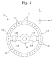
- Figure 1 is a configuration diagram illustrating the main portion of a steering operation force detecting apparatus according to the first embodiment of the present invention.
- Figure 2 is a block diagram illustrating an electrical system circuit of the steering operation force detecting apparatus according to the first embodiment of the present invention.
- Figure 3 is a flowchart explaining a processing operation according to the first embodiment of the present invention.
- Figure 4 is a view explaining a detection operation according to the first embodiment of the present invention.
- reference numeral 10 denotes a steering operation force detecting apparatus, which is constituted by a steering wheel rim 11 (11A, 11B), a steering arm 12 (12A, 12B) coupling the steering wheel rim 11 and a steering wheel hub 13, and a processing unit 20.
- the steering wheel rim 11 is equally divided into two portions of the first divided portion 11A and the second divided portion 11B in the steering direction (rotation direction) along a vertical line.
- the first divided portion 11A is coupled to the steering wheel hub 13 by the steering arm 12A.
- the second divided portion 11B is coupled to the steering wheel hub 13 by the steering arm 12B.
- force sensors 21A and 21B for detecting a force and a moment applied to the steering arms 12A and 12B are provided substantially in each central portion of the steering arms 12A and 12B in the longitudinal direction.
- a known six-component load cell capable of detecting three component forces in x-axis, y-axis, and z-axis directions orthogonal to each other, and moments around the three axes at the same time is used as the force sensors 21A and 21B, for example.
- the force sensors 21A and 21B are mounted corresponding to an x, y, z orthogonal coordinate system in which the longitudinal direction of the steering arms 12A and 12B is an x axis and the direction orthogonal to the x axis in the rotational plane of the steering wheel rim 11 is a y axis with the coordinate of a central point 131 (intersection of the plane with the rotation axis) of the steering wheel hub 13 in the rotational plane being the origin.
- a plurality of contact sensors 22 are arranged at regular intervals in the circumferential direction in each of the first and second divided portions 11A and 11B of the steering wheel rim 11.
- the contact sensors 22 are for detecting a position on the steering wheel rim 11 which a driver grips with his/her hands.
- a pressure-sensitive sensor, an electrode-type touch sensor, or an optical sensor can be used, for example.
- the processing unit 20 includes a sensor interface 23, an arithmetic processing section 24, a storage section 25, and a data output section 26.
- the sensor interface 23 supplies driving power to the force sensors 21A, 21B and the plurality of contact sensors 22. Also, electric signals as detection results output from the force sensors 21A, 21B and the plurality of contact sensors 22 are input to the sensor interface 23. The sensor interface 23 outputs the detection result of each sensor to the arithmetic processing section 24 as digital data.
- the arithmetic processing section 24 is mainly constituted by a known CPU and a memory, and operates based on a program stored in advance in the memory. Also, the detection result of each sensor is input from the sensor interface 23 to the arithmetic processing section 24 at predetermined time intervals (for example, at one-second intervals). The arithmetic processing section 24 obtains a force applied point described below based on the detection result. Furthermore, the arithmetic processing section 24 calculates a force and a moment at the force applied point, and stores the result in the storage section 25 with the coordinate data of each sensor and the detection time data described below. Moreover, the arithmetic processing section 24 outputs the data to an unillustrated higher-level device via the data output section 26.
- the arithmetic processing section 24 deletes the data of the detection results stored in the storage section 25, or outputs the data to the unillustrated higher-level device via the data output section 26 based on the operation of an unillustrated switch or the like.
- the data of coordinates O1 and O2 of the detecting central points of the force sensors 21A and 21B and the data of the location coordinate of each contact sensor 22 in the x, y, z orthogonal coordinate system with the coordinate of the central point 131 (intersection of the plane with the rotation axis) of the steering wheel hub 13 in the rotational plane of the steering wheel rim 11 being the origin when the steering wheel rim 11 is in the position obtained when a vehicle is traveling straight are stored in advance in the storage section 25.
- the arithmetic processing section 24 calculates a distance between the respective coordinates based on the data stored in the storage section 25.
- the contact sensors 22 in each of the first and second divided portions 11A and 11B of the steering wheel rim 11 are numbered in order from the one arranged in one end of the divided portions 11A and 11B.
- the coordinate of each contact sensor 22 is stored corresponding to the number in the storage section 25.
- the force sensors 21A and 21B detect forces and moments represented by the x, y, z orthogonal coordinate with the detecting central points O1 and O2 being the center, and output the detection result. Also, each of the contact sensors 22 outputs an electric signal indicating the presence or absence of contact of a driver's hand. Only the contact sensors 22 existing in gripped regions ER1 and ER2 by driver's hands output the electric signals indicating the presence of contact.
- the arithmetic processing section 24 obtains the data of the presence or absence of contact detected by each contact sensor and the data of the force and the moment detected by each force sensor via the sensor interface 23 (SA1, SA2).
- the arithmetic processing section 24 stores the respective data in the storage section 25 with the detection time data by correlating the respective data with the coordinate data of each sensor (SA3).
- the arithmetic processing section 24 calculates the coordinates of force applied points FP1 and FP2 based on the detection result of each sensor and the coordinate data of each sensor (SA4), and also, calculates forces and moments applied to the force applied points FP1 and FP2 (SA5).
- the arithmetic processing section 24 stores the calculation results of the forces and the moments at the force applied points in the storage section 25 with the coordinate data of each sensor and the detection time data described below (SA6). Also, the arithmetic processing section 24 outputs the data to the unillustrated higher-level device via the data output section 26 (SA7).
- the arithmetic processing section 24 resets the counted time of a timer (SA8), and starts to count time.
- a counted time T of the timer reaches a predetermined time T1 or more (SA9), the process moves to the process of SA1 described above and the above processes are repeated.
- T1 is set to one second in the present embodiment, the value of the time T1 is not limited to this value and may be set to any value.
- the arithmetic processing section 24 obtains the central coordinate of the coordinates of all the contact sensors 22 existing in each region of the gripped regions ER1 and ER2 by driver's hands as the coordinates of the force applied points FP1 and FP2.
- a force F FP1 and a moment M FP1 at the force applied point FP1 described above can be calculated by using the following Equation (1) and Equation (2).
- a force F FP2 and a moment M FP2 at the force applied point FP2 can be similarly calculated.
- F represents a force detected by the force sensor 21A
- M represents a moment detected by the force sensor 21A
- a represents a position vector from the detecting central point of the force sensor 21A to the force applied point FP1.
- the calculation of the force and the moment at the force applied point FP2 is similarly performed as described above.
- the force and the moment applied to each of the divided portions 11A and 11B of the steering wheel rim 11 are detected by the force sensors 21A and 21B. Also, the force applied points FP1 and FP2 of driver's hands which grip the divided portions 11A and 11B of the steering wheel rim 11 are detected using the contact sensors 22. Moreover, the forces and the moments at the force applied points FP1 and FP2 are calculated based on the detection results, and the calculation results are output. Therefore, it is possible to know in detail how much force or moment is applied to the force applied points FP1 and FP2 on the steering wheel rim 11 during a steering operation.
- the apparatus of the present invention it is possible to know in detail and in real-time the sense of driving during steering by a driver as the data of the forces or the moments applied to the steering wheel rim (steering wheel) 11 gripped by the driver during steering.
- the present invention can be thereby effectively utilized in the performance evaluation or the like of new-model cars and tires.
- Figures 5 to 9 illustrate the second embodiment of the present invention.
- Figure 5 is a block diagram illustrating an electrical system circuit of a steering operation force detecting apparatus according to the second embodiment of the present invention.
- Figure 6 is a configuration diagram illustrating the main portion of the steering operation force detecting apparatus according to the second embodiment of the present invention.
- Figures 7 and 8 are views explaining a detection operation according to the second embodiment of the present invention.
- Figure 9 is a flowchart explaining a processing operation according to the second embodiment of the present invention.
- a contact-pressure sensor 31 is provided instead of the contact sensor 22 of the first embodiment, and a processing unit 20B corresponding thereto is provided.
- the contact-pressure sensor 31 detects a contact pressure applied to the contact-pressure sensor 31 when a driver grips the steering wheel rim 11, and outputs an electric signal of the detection result to a sensor interface 32.
- the processing unit 20B includes the sensor interface 32, an arithmetic processing section 33, a storage section 34, and the data output section 26.
- the sensor interface 32 supplies driving power to the force sensors 21A, 21B and a plurality of contact-pressure sensors 31. Also, electric signals as detection results output from the force sensors 21A, 21B and the plurality of contact-pressure sensors 31 are input to the sensor interface 32. The sensor interface 32 outputs the detection result of each sensor to the arithmetic processing section 33 as digital data.
- the arithmetic processing section 33 is mainly constituted by a known CPU and a memory, and operates based on a program stored in advance in the memory. Also, the detection result of each sensor is input from the sensor interface 32 to the arithmetic processing section 33 at predetermined time intervals (for example, at one-second intervals). The arithmetic processing section 33 obtains a force applied point based on the contact pressure as described below. Furthermore, the arithmetic processing section 33 calculates a force and a moment at the force applied point, and stores the result in the storage section 34 with the coordinate data of each sensor and the detection time data described below. Moreover, the arithmetic processing section 33 outputs the data to an unillustrated higher-level device via the data output section 26.
- the arithmetic processing section 33 deletes the data of the detection results stored in the storage section 34, or outputs the data to the unillustrated higher-level device via the data output section 26 based on the operation of an unillustrated switch or the like.
- the data of coordinates O1 and O2 of the detecting central points of the force sensors 21A and 21B and the data of the location coordinate of each contact-pressure sensor 31 in the x, y, z orthogonal coordinate system with the coordinate of the central point 131 (intersection of the plane with the rotation axis) of the steering wheel hub 13 in the rotational plane of the steering wheel rim 11 being the origin when the steering wheel rim 11 is in the position obtained when a vehicle is traveling straight are stored in advance in the storage section 34.
- the arithmetic processing section 33 calculates a distance between the respective coordinates based on the data.
- the contact-pressure sensors 31 in each of the first and second divided portions 11A and 11B of the steering wheel rim 11 are numbered in order from the one arranged in one end of the divided portions 11A and 11B.
- the coordinate of each contact-pressure sensor 31 is stored corresponding to the number in the storage section 34.
- the force sensors 21A and 21B detect forces and moments represented by the x, y, z orthogonal coordinate with the detecting central points O1 and O2 being the center, and output the detection result. Also, each of the contact-pressure sensors 31 outputs an electric signal indicating the contact pressure of a driver's hand. Only the contact-pressure sensors 31 existing in gripped regions ER1 and ER2 by driver's hands output the electric signals indicating the contact pressure obtained when gripped by a driver.
- the arithmetic processing section 33 obtains the data of the contact pressure detected by each contact-pressure sensor 31 and the data of the force and the moment detected by each force sensor 21A and 21B via the sensor interface 32 (SB1, SB2).
- the arithmetic processing section 33 stores the respective data in the storage section 34 with the detection time data by correlating the respective data with the coordinate data of each sensor (SB3).
- the arithmetic processing section 33 calculates the coordinates of force applied points FP1 and FP2 based on the detection result of each sensor and the coordinate data of each sensor (SB4), and also, calculates forces and moments applied to the force applied points FP1 and FP2 (SB5).
- the coordinate of the force applied point FP1 is obtained by using a known weighted average obtained from a contact pressure distribution C:[ ( ⁇ 1, p1), ( ⁇ 2, p2), ( ⁇ 3, p3) to ( ⁇ n, pn)] by the product of an angle ⁇ from a y axis 132 passing through the origin 131 of the orthogonal coordinate to each contact-pressure sensor 31 existing in the gripped region ER1 and a contact pressure p detected by each contact-pressure sensor 31 existing in the gripped region ER1 as shown in Figure 8 .
- the coordinate of the force applied point FP11 is obtained by using the weighted average obtained from the contact pressure distribution C using an angle ⁇ i and a detected pressure pi of a contact-pressure sensor 31i, an angle ⁇ (i+1) and a detected pressure p(i+1) of a contact-pressure sensor 31(i+1), an angle ⁇ (i+2) and a detected pressure p(i+2) of a contact-pressure sensor 31(i+2), and an angle ⁇ (i+3) and a detected pressure p(i+3) of a contact-pressure sensor 31(i+3).
- the force applied point FP2 in the gripped region ER2 is similarly obtained.
- a pressure peak position in a pressure distribution detected by each contact-pressure sensor 31 may be simply obtained as the force applied point.
- the arithmetic processing section 33 stores the calculation results of the forces and the moments at the force applied points in the storage section 34 with the coordinate data of each sensor and the detection time data described below (SB6). Also, the arithmetic processing section 33 outputs the data to the unillustrated higher-level device via the data output section 26 (SB7).
- the arithmetic processing section 33 resets the counted time of a timer (SB8), and starts to count time.
- a counted time T of the timer reaches a predetermine time T1 or more (SB9), the process moves to the process of SB1 described above and the above processes are repeated.
- a force F FP1 and a moment M FP1 at the force applied point FP1 described above can be calculated by using the Equation (1) and the Equation (2) described above.
- a force F FP2 and a moment M FP2 at the force applied point FP2 can be similarly calculated.
- the contact pressure of a driver's hand on the steering wheel rim 11 is detected by the contact-pressure sensors 31 arranged in each of the divided portions 11A and 11B of the steering wheel rim 11. Also, the force applied points FP1 and FP2 are obtained based on the contact pressure distribution obtained by the contact-pressure sensors 31. Moreover, the forces and the moments at the force applied points FP1 and FP2 are calculated based on the detection results, and the calculation results are output. Therefore, it is possible to know in detail how much force or moment is applied to the force applied points FP1 and FP2 on the steering wheel rim 11 during a steering operation.
- the apparatus of the present invention it is possible to know in detail and in real-time the sense of driving during steering by a driver as the data of the forces or the moments applied to the steering wheel rim (steering wheel) 11 gripped by the driver during steering.
- the present invention can be thereby effectively utilized in the performance evaluation or the like.
- Figures 10 to 15 illustrate the third embodiment of the present invention.
- Figure 10 is a block diagram illustrating an electrical system circuit of a steering operation force detecting apparatus according to the third embodiment of the present invention.
- Figure 11 is a configuration diagram illustrating the main portion of the steering operation force detecting apparatus according to the third embodiment of the present invention.
- Figures 12 to 14 are views explaining a detection operation according to the third embodiment of the present invention.
- Figure 15 is a flowchart explaining a processing operation according to the third embodiment of the present invention.
- a steer angle sensor 41 is provided in addition to the configuration of the second embodiment, and a processing unit 20C corresponding thereto is provided.
- the steer angle sensor 41 is provided in the steering wheel hub 13, and detects a steer angle ⁇ of the steering wheel rim 11 to output an electric signal corresponding to the detection result to a sensor interface.
- the processing unit 20C includes a sensor interface 42, an arithmetic processing section 43, a storage section 44, and the data output section 26.
- the sensor interface 42 supplies driving power to the steer angle sensor 41, the force sensors 21A, 21B and the plurality of contact-pressure sensors 31. Also, electric signals output from the sensors are input to the sensor interface 42. The sensor interface 42 outputs the detection result of each sensor to the arithmetic processing section 43 as digital data.
- the arithmetic processing section 43 is mainly constituted by a known CPU and a memory, and operates based on a program stored in advance in the memory. Also, the detection result of each sensor is input from the sensor interface 42 to the arithmetic processing section 43 at predetermined time intervals (for example, at one-second intervals). The arithmetic processing section 43 obtains a force applied point based on the contact pressure as described below. Furthermore, the arithmetic processing section 43 calculates a force and a moment at the force applied point, and stores the result in the storage section 44 with the steer angle ⁇ , the coordinate data of each sensor and the detection time data described below.
- the arithmetic processing section 43 transforms the coordinates of the force and the moment applied to the force applied point as described below, and stores the data of the coordinates of the force applied point and the force and the moment applied to the force applied point after transformation in the storage section 44. Moreover, the arithmetic processing section 43 outputs the data to an unillustrated higher-level device via the data output section 26.
- the arithmetic processing section 43 deletes the data of the detection results stored in the storage section 44, or outputs the data to the unillustrated higher-level device via the data output section 26 based on the operation of an unillustrated switch or the like.
- the data of coordinates O1 and O2 of the detecting central points of the force sensors 21A and 21B and the data of the location coordinate of each contact-pressure sensor 31 in the x, y, z orthogonal coordinate system with the coordinate of the central point 131 (intersection of the plane with the rotation axis) of the steering wheel hub 13 in the rotational plane of the steering wheel rim 11 being the origin when the steering wheel rim 11 is in the position obtained when a vehicle is traveling straight are stored in advance in the storage section 44.
- the arithmetic processing section 43 calculates a distance between the respective coordinates based on the data.
- the contact-pressure sensors 31 in each of the first and second divided portions 11A and 11B of the steering wheel rim 11 are numbered in order from the one arranged in one end of the divided portions 11A and 11B.
- the coordinate of each contact-pressure sensor 31 is stored corresponding to the number in the storage section 44.
- the force sensors 21A and 21B detect forces and moments represented by the x, y, z orthogonal coordinate with the detecting central points 01 and 02 being the center, and output the detection result. Also, each of the contact-pressure sensors 31 outputs an electric signal indicating the contact pressure of a driver's hand. Only the contact-pressure sensors 31 existing in gripped regions ER1 and ER2 by driver's hands output the electric signals indicating the contact pressure obtained when gripped by a driver.
- the arithmetic processing section 43 obtains the data of the contact pressure detected by each contact-pressure sensor 31, the data of the force and the moment detected by each force sensor 21A and 21B, and the data of the steer angle ⁇ detected by the steer angle sensor 41 via the sensor interface 42 (SC1, SC2, SC3).
- the arithmetic processing section 43 stores the respective data in the storage section 44 with the detection time data by correlating the respective data with the coordinate data of each sensor (SC4).
- the arithmetic processing section 43 calculates the coordinates of force applied points FP1 and FP2 based on the detection result of each sensor and the coordinate data of each sensor (SC5), and also, calculates forces and moments applied to the force applied points FP1 and FP2 (SC6).
- the coordinate of the force applied point FP1 is obtained by using a known weighted average obtained from a contact pressure distribution C:[ ( ⁇ 1, p1), ( ⁇ 2, p2), ( ⁇ 3, p3) to ( ⁇ n, pn)] (n is a natural number) by the product of an angle ⁇ from a y axis 132 passing through the origin 131 of the orthogonal coordinate to each contact-pressure sensor 31 existing in the gripped region ER1 and a contact pressure p detected by each contact-pressure sensor 31 existing in the gripped region ER1 as in the second embodiment described above.
- the force applied point FP2 in the gripped region ER2 is similarly obtained.
- a pressure peak position in a pressure distribution detected by each contact-pressure sensor 31 may be simply obtained as the force applied point.
- the arithmetic processing section 43 stores the calculation results of the forces and the moments applied to the force applied points FP1 and FP2 in the storage section 44 with the coordinate data of each sensor and the detection time data described below, and performs a coordinate transformation of the forces and the moments applied to the force applied points FP1 and FP2 (SC7).
- the coordinate is transformed into an x, y', z' orthogonal coordinate in which the horizontal direction in the rotational plane of the steering wheel rim 11 is an x' axis and the direction orthogonal to the x' axis in the plane is a y' axis with the coordinate of the central point 131 (intersection of the plane with the rotation axis) of the steering wheel hub 13 in the rotational plane being the origin.
- the arithmetic processing section 43 stores the data of the forces and the moments applied to the force applied points FP1 and FP2 represented by the coordinate-transformed orthogonal coordinate system in the storage section 44 (SC8). Also, the arithmetic processing section 43 outputs the data obtained from each sensor with the detection time data and the calculated data to the unillustrated higher-level device via the data output section 26 (SC9).
- the arithmetic processing section 43 resets the counted time of a timer (SC10), and starts to count time.
- a counted time T of the timer reaches a predetermined time T1 or more (SC11)
- the process moves to the process of SC1 described above and the above processes are repeated.
- a force F FP1 and a moment M FP1 at the force applied point FP1 described above can be calculated by using the Equation (1) and the Equation (2) described above.
- a force F FP2 and a moment M FP2 at the force applied point FP2 can be similarly calculated.
- the coordinates of a pushing/pulling force, a vertical force and a moment at each of the force applied points FP1 and FP2 may be transformed into an x", y", z" orthogonal coordinate system in which the tangential direction of the steering wheel rim 11 is a y" axis and the normal direction is an x" axis with the force applied points FP1 and FP2 being the origin.
- the force in the tangential direction is a force for generating steering torque.
- the contact pressure of a diver's hand on the steering wheel rim 11 is detected by the contact-pressure sensors 31 arranged in each of the divided portions 11A and 11B of the steering wheel rim 11. Also, the force applied points FP1 and FP2 are obtained based on the contact pressure distribution obtained by the contact-pressure sensors 31. Moreover, the forces and the moments at the force applied points FP1 and FP2 are calculated based on the detection results, and the calculation results are output. Therefore, it is possible to know in detail how much force or moment is applied to the force applied points FP1 and FP2 on the steering wheel rim 11 during a steering operation.
- the apparatus of the present invention it is possible to know in detail and in real-time the sense of driving during steering by a driver as the data of the forces or the moments applied to the steering wheel rim (steering wheel) 11 gripped by the driver during steering.
- the present invention can be thereby effectively utilized in the performance evaluation or the like of new-model cars and tires.
- the present invention is not limited to the configuration of each of the above embodiments.
- the steering wheel rim 11 is divided into two portions of the two divided portions 11A and 11B in the above embodiments, the steering wheel rim 11 may be divided into three or more portions, for example. Also, it is preferable that the method of obtaining the force applied points FP1 and FP2, the coordinate system or the like are appropriately determined according to data usage or the like.
Landscapes
- Engineering & Computer Science (AREA)
- Chemical & Material Sciences (AREA)
- Combustion & Propulsion (AREA)
- Transportation (AREA)
- Mechanical Engineering (AREA)
- Physics & Mathematics (AREA)
- General Physics & Mathematics (AREA)
- Force Measurement Appropriate To Specific Purposes (AREA)
- Steering Controls (AREA)
Applications Claiming Priority (2)
| Application Number | Priority Date | Filing Date | Title |
|---|---|---|---|
| JP2007111416A JP4475288B2 (ja) | 2007-04-20 | 2007-04-20 | 操舵操作力検出装置 |
| PCT/JP2008/057316 WO2008133099A1 (ja) | 2007-04-20 | 2008-04-15 | 操舵操作力検出装置 |
Publications (3)
| Publication Number | Publication Date |
|---|---|
| EP2067687A1 true EP2067687A1 (de) | 2009-06-10 |
| EP2067687A4 EP2067687A4 (de) | 2011-04-27 |
| EP2067687B1 EP2067687B1 (de) | 2012-07-25 |
Family
ID=39925557
Family Applications (1)
| Application Number | Title | Priority Date | Filing Date |
|---|---|---|---|
| EP08740402A Active EP2067687B1 (de) | 2007-04-20 | 2008-04-15 | Vorrichtung zur erkennung einer lenkbetriebskraft |
Country Status (4)
| Country | Link |
|---|---|
| US (1) | US8099215B2 (de) |
| EP (1) | EP2067687B1 (de) |
| JP (1) | JP4475288B2 (de) |
| WO (1) | WO2008133099A1 (de) |
Cited By (5)
| Publication number | Priority date | Publication date | Assignee | Title |
|---|---|---|---|---|
| DE102009057809A1 (de) * | 2009-12-10 | 2011-06-16 | Leopold Kostal Gmbh & Co. Kg | Torsionsmodul |
| DE102010017851A1 (de) * | 2010-04-22 | 2011-10-27 | Leopold Kostal Gmbh & Co. Kg | Torsionsmodul |
| DE102011080552A1 (de) * | 2011-08-05 | 2013-02-07 | Robert Bosch Gmbh | Lenkrad und Lenkmomentsensor für ein Kraftfahrzeug |
| WO2014199020A1 (fr) * | 2013-06-12 | 2014-12-18 | Université De Valenciennes Et Du Hainaut-Cambrésis | Systeme de direction assistee electrique |
| WO2015198039A1 (en) * | 2014-06-25 | 2015-12-30 | Trw Limited | An electric power assisted steering system |
Families Citing this family (23)
| Publication number | Priority date | Publication date | Assignee | Title |
|---|---|---|---|---|
| DE102006031207B3 (de) * | 2006-07-03 | 2007-11-22 | Takata-Petri Ag | Sensorsystem für ein Lenkrad eines Kraftfahrzeuges |
| KR101032635B1 (ko) * | 2009-04-16 | 2011-05-09 | 한국과학기술원 | 자동차 네비게이션 시스템, 자동차 네비게이션용 스티어링 휠 및 커버, 이를 포함하는 자동차 및 이를 이용한 자동차 주행안내방법 |
| JP5444958B2 (ja) * | 2009-08-31 | 2014-03-19 | 株式会社豊田中央研究所 | ステアリング操作状態推定装置、及びプログラム |
| JP5549425B2 (ja) * | 2010-06-30 | 2014-07-16 | 横浜ゴム株式会社 | 操舵操作力検出装置 |
| JP5664073B2 (ja) * | 2010-09-24 | 2015-02-04 | 横浜ゴム株式会社 | 操縦感覚評価システムおよび操縦感覚評価方法 |
| KR101189568B1 (ko) * | 2010-12-01 | 2012-10-11 | 현대자동차주식회사 | 스티어링 휠 레벨러 자동화 시스템 및 방법 |
| US8738224B2 (en) * | 2011-01-12 | 2014-05-27 | GM Global Technology Operations LLC | Steering wheel system |
| US20120232751A1 (en) * | 2011-03-07 | 2012-09-13 | Jorge Guspan | Pressure-Sensitive Steering Wheel Controls |
| JP5871422B2 (ja) * | 2011-06-22 | 2016-03-01 | ティーケー ホールディングス インク.Tk Holdings Inc. | 車両用ステアリングホイールのためのセンサシステム |
| KR101350177B1 (ko) | 2011-12-09 | 2014-01-16 | 현대자동차주식회사 | 스티어링 휠 내장형 스위치 모듈 |
| US9096262B2 (en) * | 2012-05-25 | 2015-08-04 | Ford Global Technologies, Llc | Hands-on-off steering wheel detection for motor vehicle |
| JP5985384B2 (ja) * | 2012-12-27 | 2016-09-06 | トヨタテクニカルディベロップメント株式会社 | 作用力測定装置および作用力測定方法 |
| US8909428B1 (en) * | 2013-01-09 | 2014-12-09 | Google Inc. | Detecting driver grip on steering wheel |
| JP6337376B2 (ja) * | 2013-10-09 | 2018-06-06 | シャープ株式会社 | 操作装置及び移動体 |
| DE102014007163B3 (de) * | 2014-05-15 | 2015-09-24 | Florian Gerber | Überwachungssystem für Kraftfahrzeuge |
| US9604649B1 (en) * | 2016-02-12 | 2017-03-28 | GM Global Technology Operations LLC | Hands-off detection enhancement by means of a synthetic signal |
| CN108263338B (zh) * | 2016-12-30 | 2021-06-15 | 华为技术有限公司 | 汽车、方向盘以及驾驶员身份识别方法 |
| CN107582081B (zh) * | 2017-10-31 | 2020-01-10 | 京东方科技集团股份有限公司 | 一种检测装置及一种疲劳检测系统 |
| CN109050647B (zh) * | 2018-06-30 | 2021-08-10 | 江南大学 | 一种检测驾驶疲劳度系统 |
| JP7066582B2 (ja) * | 2018-09-12 | 2022-05-13 | 本田技研工業株式会社 | 判定システム、車両制御システム、車両、判定方法、及びプログラム |
| CN112298176B (zh) * | 2019-12-27 | 2022-11-04 | 苏州鱼得水电气科技有限公司 | 一种基于大数据的车辆变道监控和预测系统 |
| FR3115262B1 (fr) * | 2020-10-16 | 2023-01-20 | Commissariat Energie Atomique | Dispositif de détection de contact multipoint et procédé |
| EP4015474B1 (de) | 2020-12-16 | 2023-06-14 | Heraeus Quarzglas GmbH & Co. KG | Verfahren zur herstellung einer vorform einer antiresonanten hohlkernfaser |
Citations (2)
| Publication number | Priority date | Publication date | Assignee | Title |
|---|---|---|---|---|
| JP2005247255A (ja) * | 2004-03-08 | 2005-09-15 | Koyo Seiko Co Ltd | トルク検出装置およびこれを備えるパワーステアリング装置 |
| US20060118350A1 (en) * | 2004-12-08 | 2006-06-08 | Honda Motor Co., Ltd. | Vehicle control apparatus |
Family Cites Families (10)
| Publication number | Priority date | Publication date | Assignee | Title |
|---|---|---|---|---|
| JPS62198562A (ja) * | 1986-02-26 | 1987-09-02 | Hino Motors Ltd | ステアリング・ホイ−ル |
| JPH0411567A (ja) * | 1990-04-28 | 1992-01-16 | Toyoda Gosei Co Ltd | ステアリングホイール |
| JPH05675A (ja) * | 1991-06-13 | 1993-01-08 | Toyota Motor Corp | 車両の補助操舵装置 |
| JPH05310130A (ja) * | 1991-08-09 | 1993-11-22 | Toyoda Gosei Co Ltd | ステアリングホイール |
| JPH05345569A (ja) | 1991-10-14 | 1993-12-27 | Toyoda Gosei Co Ltd | ステアリングホイール |
| DE19631502C1 (de) | 1996-08-03 | 1998-01-22 | Bosch Gmbh Robert | Lenkrad mit optoelektronischem Sensor |
| DE10027922A1 (de) | 2000-06-06 | 2002-01-24 | Bosch Gmbh Robert | Verfahren zum Detektieren der Position von Händen auf einem Lenkrad |
| JP2004271450A (ja) * | 2003-03-11 | 2004-09-30 | Toyota Central Res & Dev Lab Inc | 接線力センサ及びステアリングホイール |
| US6868934B2 (en) * | 2003-07-09 | 2005-03-22 | Honda Giken Kogyo Kabushiki Kaisha | Variable power steering assist using driver grip pressure |
| JP4814594B2 (ja) * | 2005-09-14 | 2011-11-16 | 日立オートモティブシステムズ株式会社 | 車載設備の操作装置 |
-
2007
- 2007-04-20 JP JP2007111416A patent/JP4475288B2/ja active Active
-
2008
- 2008-04-15 WO PCT/JP2008/057316 patent/WO2008133099A1/ja active Application Filing
- 2008-04-15 EP EP08740402A patent/EP2067687B1/de active Active
- 2008-04-15 US US12/375,925 patent/US8099215B2/en not_active Expired - Fee Related
Patent Citations (2)
| Publication number | Priority date | Publication date | Assignee | Title |
|---|---|---|---|---|
| JP2005247255A (ja) * | 2004-03-08 | 2005-09-15 | Koyo Seiko Co Ltd | トルク検出装置およびこれを備えるパワーステアリング装置 |
| US20060118350A1 (en) * | 2004-12-08 | 2006-06-08 | Honda Motor Co., Ltd. | Vehicle control apparatus |
Non-Patent Citations (1)
| Title |
|---|
| See also references of WO2008133099A1 * |
Cited By (7)
| Publication number | Priority date | Publication date | Assignee | Title |
|---|---|---|---|---|
| DE102009057809A1 (de) * | 2009-12-10 | 2011-06-16 | Leopold Kostal Gmbh & Co. Kg | Torsionsmodul |
| DE102010017851A1 (de) * | 2010-04-22 | 2011-10-27 | Leopold Kostal Gmbh & Co. Kg | Torsionsmodul |
| DE102010017851B4 (de) | 2010-04-22 | 2023-12-07 | Kostal Automobil Elektrik Gmbh & Co. Kg | Torsionsmodul |
| DE102011080552A1 (de) * | 2011-08-05 | 2013-02-07 | Robert Bosch Gmbh | Lenkrad und Lenkmomentsensor für ein Kraftfahrzeug |
| WO2014199020A1 (fr) * | 2013-06-12 | 2014-12-18 | Université De Valenciennes Et Du Hainaut-Cambrésis | Systeme de direction assistee electrique |
| WO2015198039A1 (en) * | 2014-06-25 | 2015-12-30 | Trw Limited | An electric power assisted steering system |
| US10005491B2 (en) | 2014-06-25 | 2018-06-26 | Trw Limited | Electric power assisted steering system |
Also Published As
| Publication number | Publication date |
|---|---|
| JP4475288B2 (ja) | 2010-06-09 |
| US20100030429A1 (en) | 2010-02-04 |
| EP2067687A4 (de) | 2011-04-27 |
| US8099215B2 (en) | 2012-01-17 |
| JP2008265528A (ja) | 2008-11-06 |
| WO2008133099A1 (ja) | 2008-11-06 |
| EP2067687B1 (de) | 2012-07-25 |
Similar Documents
| Publication | Publication Date | Title |
|---|---|---|
| EP2067687B1 (de) | Vorrichtung zur erkennung einer lenkbetriebskraft | |
| US10671170B2 (en) | Haptic driving guidance system | |
| JP5840980B2 (ja) | 操作位置検出装置、及び車載装置 | |
| EP2383624A2 (de) | Vorrichtung und Verfahren zur Erkennung der Kontaktposition eines Roboters | |
| US20150097508A1 (en) | Method for measuring displacement of planar motor rotor | |
| CN101990733B (zh) | 磁极位置检测装置及方法 | |
| JPWO2012066821A1 (ja) | 角速度検出装置、角速度検出方法、移動状態検出装置およびナビゲーション装置 | |
| WO2009061235A3 (fr) | Procédé de détermination des paramètres de navigation par un système de navigation inertielle sans plate-forme | |
| JP2013181777A (ja) | 車載装置 | |
| JP4420100B2 (ja) | 身体部位検出装置 | |
| EP3537098A1 (de) | Messvorrichtung | |
| JP2008116339A (ja) | センサ装置およびセンサ装置を備えた車両制御システム | |
| JP5874435B2 (ja) | 車両用入力装置 | |
| CN101801754B (zh) | 驾驶员状态推断装置 | |
| US10203204B2 (en) | Rotation angle detection device | |
| JP4878443B2 (ja) | 計器表示装置及び計器表示方法 | |
| JP2012141421A (ja) | 塗装吹付け訓練機 | |
| JP2004333196A (ja) | 波動歯車装置の回転角度検出装置 | |
| JP2014153266A (ja) | 車両用ドアハンドルの操作力測定装置 | |
| JPH0962437A (ja) | コンピュータ入力装置 | |
| CN110520705B (zh) | 三轴力检测装置 | |
| KR20120077866A (ko) | 관성 센서를 이용한 선택적인 동작 인식 장치 | |
| US20210154851A1 (en) | Coordinate-system setting system and coordinate-system setting method | |
| CN104567762A (zh) | 工程机械臂架在线监测方法、设备以及系统 | |
| JP6226175B2 (ja) | 操作性評価装置、方法およびプログラム |
Legal Events
| Date | Code | Title | Description |
|---|---|---|---|
| PUAI | Public reference made under article 153(3) epc to a published international application that has entered the european phase |
Free format text: ORIGINAL CODE: 0009012 |
|
| 17P | Request for examination filed |
Effective date: 20090128 |
|
| AK | Designated contracting states |
Kind code of ref document: A1 Designated state(s): AT BE BG CH CY CZ DE DK EE ES FI FR GB GR HR HU IE IS IT LI LT LU LV MC MT NL NO PL PT RO SE SI SK TR |
|
| AX | Request for extension of the european patent |
Extension state: AL BA MK RS |
|
| A4 | Supplementary search report drawn up and despatched |
Effective date: 20110328 |
|
| GRAP | Despatch of communication of intention to grant a patent |
Free format text: ORIGINAL CODE: EPIDOSNIGR1 |
|
| GRAS | Grant fee paid |
Free format text: ORIGINAL CODE: EPIDOSNIGR3 |
|
| DAX | Request for extension of the european patent (deleted) | ||
| GRAA | (expected) grant |
Free format text: ORIGINAL CODE: 0009210 |
|
| AK | Designated contracting states |
Kind code of ref document: B1 Designated state(s): DE |
|
| RBV | Designated contracting states (corrected) |
Designated state(s): DE |
|
| REG | Reference to a national code |
Ref country code: DE Ref legal event code: R096 Ref document number: 602008017409 Country of ref document: DE Effective date: 20120920 |
|
| PLBE | No opposition filed within time limit |
Free format text: ORIGINAL CODE: 0009261 |
|
| STAA | Information on the status of an ep patent application or granted ep patent |
Free format text: STATUS: NO OPPOSITION FILED WITHIN TIME LIMIT |
|
| 26N | No opposition filed |
Effective date: 20130426 |
|
| REG | Reference to a national code |
Ref country code: DE Ref legal event code: R097 Ref document number: 602008017409 Country of ref document: DE Effective date: 20130426 |
|
| P01 | Opt-out of the competence of the unified patent court (upc) registered |
Effective date: 20230512 |
|
| PGFP | Annual fee paid to national office [announced via postgrant information from national office to epo] |
Ref country code: DE Payment date: 20230228 Year of fee payment: 16 |