EP2065264A2 - Insassenschutzvorrichtung - Google Patents
Insassenschutzvorrichtung Download PDFInfo
- Publication number
- EP2065264A2 EP2065264A2 EP08020450A EP08020450A EP2065264A2 EP 2065264 A2 EP2065264 A2 EP 2065264A2 EP 08020450 A EP08020450 A EP 08020450A EP 08020450 A EP08020450 A EP 08020450A EP 2065264 A2 EP2065264 A2 EP 2065264A2
- Authority
- EP
- European Patent Office
- Prior art keywords
- airbag
- airbag body
- inflating portion
- seat
- occupant
- Prior art date
- Legal status (The legal status is an assumption and is not a legal conclusion. Google has not performed a legal analysis and makes no representation as to the accuracy of the status listed.)
- Granted
Links
- 210000000689 upper leg Anatomy 0.000 claims abstract description 36
- 210000004705 lumbosacral region Anatomy 0.000 claims abstract description 23
- 239000012530 fluid Substances 0.000 claims description 18
- 239000004744 fabric Substances 0.000 description 43
- 230000004308 accommodation Effects 0.000 description 10
- 238000003780 insertion Methods 0.000 description 10
- 230000037431 insertion Effects 0.000 description 10
- 238000009958 sewing Methods 0.000 description 8
- 230000000452 restraining effect Effects 0.000 description 5
- 210000001217 buttock Anatomy 0.000 description 3
- 239000003795 chemical substances by application Substances 0.000 description 3
- 238000004891 communication Methods 0.000 description 3
- 210000003127 knee Anatomy 0.000 description 3
- 239000000853 adhesive Substances 0.000 description 2
- 230000001070 adhesive effect Effects 0.000 description 2
- 238000001514 detection method Methods 0.000 description 2
- 239000002360 explosive Substances 0.000 description 2
- 238000010438 heat treatment Methods 0.000 description 2
- 230000036961 partial effect Effects 0.000 description 2
- 238000005192 partition Methods 0.000 description 2
- 238000003466 welding Methods 0.000 description 2
- 239000002759 woven fabric Substances 0.000 description 2
- 239000004952 Polyamide Substances 0.000 description 1
- 229910000831 Steel Inorganic materials 0.000 description 1
- 230000001133 acceleration Effects 0.000 description 1
- 238000013459 approach Methods 0.000 description 1
- 238000005452 bending Methods 0.000 description 1
- 238000007664 blowing Methods 0.000 description 1
- 210000000038 chest Anatomy 0.000 description 1
- 230000003247 decreasing effect Effects 0.000 description 1
- 238000010586 diagram Methods 0.000 description 1
- 230000002401 inhibitory effect Effects 0.000 description 1
- 239000010985 leather Substances 0.000 description 1
- 210000002414 leg Anatomy 0.000 description 1
- 239000000463 material Substances 0.000 description 1
- 239000002184 metal Substances 0.000 description 1
- 239000000203 mixture Substances 0.000 description 1
- 229920002647 polyamide Polymers 0.000 description 1
- 229920000728 polyester Polymers 0.000 description 1
- 230000002829 reductive effect Effects 0.000 description 1
- 230000000630 rising effect Effects 0.000 description 1
- 239000010959 steel Substances 0.000 description 1
- 238000009941 weaving Methods 0.000 description 1
- 238000004804 winding Methods 0.000 description 1
Images




Classifications
-
- B—PERFORMING OPERATIONS; TRANSPORTING
- B60—VEHICLES IN GENERAL
- B60R—VEHICLES, VEHICLE FITTINGS, OR VEHICLE PARTS, NOT OTHERWISE PROVIDED FOR
- B60R21/00—Arrangements or fittings on vehicles for protecting or preventing injuries to occupants or pedestrians in case of accidents or other traffic risks
- B60R21/02—Occupant safety arrangements or fittings, e.g. crash pads
- B60R21/16—Inflatable occupant restraints or confinements designed to inflate upon impact or impending impact, e.g. air bags
- B60R21/20—Arrangements for storing inflatable members in their non-use or deflated condition; Arrangement or mounting of air bag modules or components
- B60R21/207—Arrangements for storing inflatable members in their non-use or deflated condition; Arrangement or mounting of air bag modules or components in vehicle seats
Definitions
- the present invention relates to an occupant protection apparatus applied to a vehicle seat. Specifically, the present invention relates to an occupant protection apparatus that inflates an airbag installed in a seat portion of a seat with inflation fluid such as inflation gas to raise the seat face, thereby inhibiting the lumbar region of an occupant restrained by a seat belt apparatus from moving forward.
- inflation fluid such as inflation gas
- the "submarine phenomenon" can occur even if an occupant is restrained by a seat belt apparatus. Specifically, in the submarine phenomenon, the lumbar region of an occupant restrained to a vehicle seat is disengaged from the lap belt of the seat belt apparatus and moves forward in a sinking manner.
- Various measures against the submarine phenomenon have been proposed.
- Japanese Laid-Open Patent Publication No. 2007-168599 discloses an occupant protection apparatus that includes an airbag installed in the seat portion of a vehicle seat and an inflator (inflation fluid generator) that is installed in a front portion of the airbag.
- inflation gas inflation fluid
- inflator inflation fluid generator
- inflation gas is ejected from the inflator to inflate the airbag, so that the seat surface is raised.
- the raised seat surface pushes the upper thighs of the occupant upward against the lap belt of the seat belt apparatus. This increases the restraining force of the lap belt, thereby restricting the forward movement of the occupant lumbar region.
- the interior space of the airbag is divided into several inflation portions arranged along the front-rear direction of the vehicle by means of seams.
- the inflator is located in the foremost inflation portion.
- each pair of adjacent inflation portions communicate with each other, so that inflation gas ejected from the inflator is supplied to all the inflation portions through the communication portions.
- the seams inhibits inflation gas from moving among the inflation portions even if the occupant pushes the inflated airbag forward.
- the shape of the airbag is thus prevented from being greatly changed. As a result, the forward movement of the occupant lumbar region is inhibited.
- a large volume inflation portion is provided in a rear portion of the airbag.
- the forward movement of the occupant is restricted only by pushing the upper thighs of the occupant upward by the large volume inflation portion.
- the lower thighs of the occupant are raised by a small amount, and the forward movement of the occupant lumbar region might be insufficiently inhibited.
- an occupant protection apparatus having an airbag module arranged in a seat portion of a vehicle seat.
- the seat portion has a seat surface.
- the airbag includes an inflation fluid generator.
- the airbag is inflated by a high pressure fluid ejected from the inflation fluid generator, thereby raising the seat surface to inhibit a forward movement of the lumbar region of an occupant who is seated on the seat portion and restrained by a seat belt.
- the airbag includes an airbag body that forms an outer shape of the airbag.
- the airbag body includes a rear inflating portion that is inflated below the upper thighs of the occupant, and a front inflating portion that is inflated below the lower thighs of the occupant. When the airbag is inflated, the front inflating portion is inflated to a higher position than the rear inflating portion.
- the traveling direction of the vehicle is defined as a forward direction.
- the backward, upward, downward, leftward, and rightward directions are defined with reference to the forward direction.
- “inside” and “outside” refer to the inside and the outside of the vehicle, respectively.
- a vehicle seat S has a seat portion 10, a backrest 21 that is tiltably arranged at the rear end of the seat portion 10, and a headrest 22 arranged on top of the backrest 21.
- the seat portion 10 is used to seat an occupant P that is an object to be restrained by the occupant protection apparatus.
- the seat portion 10 includes a seat cushion 11 and a seat pan 13 that supports the seat cushion 11 from below.
- the seat cushion 11 is covered with a cover 12, which is made of fabric or leather.
- An accommodation recess 14 is formed in a front portion of the seat pan 13 to accommodate a part of an airbag module AM, which will be discussed below.
- the accommodation recess 14 is shaped like a channel that has an opening extending in the widthwise direction.
- the vehicle is equipped with a seat belt apparatus 30 for restraining the occupant P seated on the vehicle seat S.
- the seat belt apparatus 30 includes belt-like webbing 31 for restraining the occupant P, a tongue 32 attached to the webbing 31 to be slidable along the webbing 31, and a buckle 33 provided on a side (right side as viewed in Fig. 3 ) of the seat portion 10.
- the tongue 32 is detachably engaged with the buckle 33.
- One end of the webbing 31 is fixed to the other side (left side as viewed in Fig. 3 ) of the seat portion 10.
- the other end of the webbing 31 can be reeled in by a seat belt retractor (not shown).
- the webbing 31 is divided into a lap belt 34 and a shoulder belt 35 at the tongue 32.
- the tongue 32 is slid relative to the webbing 31, so as to change the lengths of the lap belt 34 and the shoulder belt 35.
- the lap belt 34 refers to a section of the webbing 31 that extends from the tongue 32 to the fixed end of the webbing 31.
- the lap belt 34 extends horizontally from one side of the lumbar region Pp of the seated occupant P to the other side via a front side of the lumbar region Pp, and mainly restrains the lumbar region Pp.
- the shoulder belt 35 refers to a section of the webbing 31 that extends from the tongue 32 to the seat belt retractor.
- the shoulder belt 35 extends diagonally from a shoulder Ps of the seated occupant P to the other side of the lumbar region Pp via the front side of a thorax Pt, and mainly restrains the shoulder Ps.
- the vehicle is equipped with an occupant protection apparatus that inhibits the submarine phenomenon.
- the submarine phenomenon refers to a phenomenon in which, when an impact due to a frontal collision is applied to a vehicle from front, the lumbar region Pp of the occupant P restrained to the vehicle seat S by the seat belt apparatus 30 may be disengaged from the lap belt 34 and move forward in a sinking manner.
- the occupant protection apparatus includes the airbag module AM, an impact sensor 81, and a controller 82.
- the airbag module AM includes an airbag 40 and an inflator assembly 60.
- the structure of the airbag 40 and the inflator assembly 60 will now be described.
- the airbag 40 includes an airbag body 41, which forms the outer shape of the airbag 40. When inflated, the airbag body 41 raises a seat surface 10A of the seat portion 10.
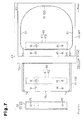
- the airbag body 41 is formed by a rectangular sheet 42 of fabric, which extends in the front-rear direction of the vehicle as shown in Fig 8 . As shown in Fig. 7 , the fabric sheet 42 is folded back upon itself at a folding line 43 defined in a center portion. Then, the folded portions of the fabric sheet 42 are joined to each other along a joint line 50, which is represented by a thick broken line in Fig. 7 , so that the airbag body 41 is formed.
- the fabric sheet 42 is formed of woven fabric, which is obtained by weaving warps and wefts made of polyester threads or polyamide threads.
- the fabric sheet 42 thus has a high stiffness and flexibility.
- a plurality of (two in this embodiment) of bolt insertion holes 44 are formed in a front end portion of the spread fabric sheet 42.
- the bolt insertion holes 44 are separated from each other along the widthwise direction.
- the insertion holes 44 are used for receiving bolts 65 of a retainer 63, which will be discussed below.
- engaging holes 45 is formed in the front section of the spread fabric sheet 42 at positions forward of the bolt the insertion holes 44.
- the engaging holes 45 are used for allowing the fabric sheet 42 to engage with the bolts 65.
- a pair of engaging holes 46 are formed in a rear end of the fabric sheet 42. The positions of the engaging holes 46 are determined so as to correspond to the engaging holes 45 when the fabric sheet 42 is folded back.
- the joint line 50 includes a pair of first joint portions 51, which are separated in the widthwise direction and extend along the side edges, a second joint portion 52, which extends along the widthwise direction to connect the rear ends of the first joint portions 51 to each other, and a pair of third joint portions 53, each of which extends from the front end of one of the first joint portions 51 toward the other first joint portion 51.
- a portion encompassed by the joint line 50 is a portion that is inflated by inflation gas G.
- the front ends of the airbag body 41 are not joined, so that an opening 54 is formed between the third joint portions 53.
- the opening 54 is required to insert the inflator assembly 60 into the airbag body 41 and to draw the harness (not shown) of the inserted inflator assembly 60 to the outside.
- Joining means along the joint line 50 includes, for example, sewing with sewing thread, adhesion with adhesive, and welding.
- the fabric sheet 42 is sewn with sewing thread.
- a single fabric sheet is used as the fabric sheet 42, and the airbag body 41 is formed by folding back the single fabric sheet. Therefore, the joint (sewing) along the second joint portion 52 in the vicinity of the folding line 43 may be omitted.
- the airbag body 41 is structured to include a rear inflating portion 48, which is inflated below the upper thighs Pf of the occupant P, and a front inflating portion 47, which is inflated below the lower thighs Pn of the occupant up to a position above the rear inflating portion 48.
- the thighs are the top parts of legs, between the knees and the hips. A part of the thigh closer to the knee is referred to as the lower thigh Pn, and a part closer to the hip is referred to as the upper thigh Pf.
- the inflator assembly 60 is used for supplying inflation gas G, which serves as inflation fluid, to the above described airbag body 41.
- the inflator assembly 60 includes an inflator 61, which serves as an inflation fluid generator, and a retainer 63, which is attached to the outside of the inflator 61.
- the inflator 61 is substantially cylindrical, and the inside of the inflator 61 is filled with high pressure inflation gas G.
- a number of gas outlets 62 are formed in a predetermined area in the longitudinal direction of the inflator 61.
- the gas outlets 62 are spaced from one another in the circumferential direction and the longitudinal direction.
- the inflator 61 is connected to a harness (not shown), which is wiring for sending control signals to the inflator 61.
- the inflator 61 is a stored gas type. When receiving a control signal through the harness, the inflator 61 detonates explosive so that high pressure inflation gas G is expanded through heating. The inflation gas G breaks a partition wall in the inflator 61 and ejects out through the gas outlet 62.
- inflator instead of the stored gas type inflator, other types of inflators may be used.
- a pyrotechnic type in which gas generating agent stored in the inflator is burned to generate inflation gas G and the gas G is ejected through gas outlet may be used.
- a hybrid type in which the pyrotechnic type and stored gas type are combined may be used.
- the retainer 63 is formed by bending a plate material such as a metal plate and is shaped as a thin cylinder extending in the widthwise direction.
- the retainer 63 has a window 64 through which the gas outlets 62 are exposed.
- a plurality of (two, in this embodiment) bolts 65 are embedded in the lower surface of the retainer 63.
- the bolts 65 are spaced apart in the widthwise direction (see Fig. 8 ).
- the inflator 61 may be integrally formed with the retainer 63.
- the inflator assembly 60 is inserted into the airbag body 41 through the opening 54 of the airbag body 41. Then, the inflator assembly 60 is arranged in a front portion of the airbag body 41 (a portion that is used as the front inflating portion 47 at the time of inflation). As shown in Figs. 2 and 4 , the bolts 65 of the retainer 63 are inserted to the bolt insertion holes 44 of the airbag body 41 from above. Further, the front end of the airbag body 41 is wrapped about the outer circumferential surface of the inflator assembly 60 toward the lower bolt 65, so that the engaging holes 45, 46 of the airbag body 41 are located below the inflator assembly 60. Subsequently, the bolts 65 of the retainer 63 are inserted into the engaging holes 45, 46, so that the wrapped portion of the airbag body 41 is engaged with the bolts 65. The engagement closes the opening 54 of the airbag body 41.
- the bolts 65 are passed through a bottom 15 of the accommodation recess 14.
- Nuts 66 are threaded to the bolts 65 so that the inflator assembly 60 is fastened to the accommodation recess 14, together with the airbag body 41.
- the fastening presses the front end of the airbag body 41 against the bottom 15 of the accommodation recess 14, which substantially closes the opening 54.
- the airbag body 41 except for the portion accommodated in the accommodation recess 14 is located between the seat cushion 11 and the seat pan 13, when spread flat without being filled with inflation gas G.
- a rear end 41 R of the flatly spread airbag body 41 is located substantially below the boundary between the upper thighs Pf and the buttocks Pb of the occupant P seated on the seat portion 10.
- an inner bag 71 is employed in addition to the basic structure of the airbag module AM, which has been described.
- the structure of the inner bag 71 will be discussed.
- the airbag 40 includes the inner bag 71, which is accommodated in the airbag body 41.
- the inner bag 71 accommodates the inflator assembly 60.
- the inner bag 71 is formed by a rectangular sheet 72 of fabric as shown in Fig 8 .
- the fabric sheet 72 is folded back onto itself at a folding line 73 defined in a center portion.
- the folded back fabric sheet 72 is formed along a pair of joint lines 74, which are represented by thick broken lines, at both sides of the fabric sheet 72.
- the fabric sheet 72 is formed of the same woven fabric as that of the airbag body 41, and thus has a high stiffness and flexibility.
- the fabric sheet 72 has a pair of bolt insertion holes 75, a pair of engaging holes 76, and a pair of engaging holes 77, which are formed in a front end portion and a rear end portion (see Fig. 8 ).
- the joint lines 74 extend along the side edges and are spaced apart in the widthwise direction. The distance between the joint lines 74 is smaller than the distance between the joint portions 51.
- a portion encompassed by the joint lines 74 is a portion that is inflated by inflation gas G.
- Joining means along the joint lines 74 includes, for example, sewing with sewing thread, adhesion with adhesive, and welding, as in the case of the joint line 50 described above.
- the sides of the fabric sheet 72 are sewn together with sewing threads.
- a single fabric sheet is used as the fabric sheet 72, and the single fabric sheet is folded back.
- a joint line may be provided along and in the vicinity of the folding line 73, so that the fabric sheet 72 is joined along the additional joint line.
- the front end of the inner bag 71 is not sewn, and an opening 78 is formed between the front ends of the joint lines 74.
- the opening 78 is required to insert the inflator assembly 60 into the inner bag 71 and to draw the harness (not shown) of the inserted inflator assembly 60 to the outside.
- the inner bag 71 is arranged in a front end portion of the airbag body 41 (a portion that becomes the front inflating portion 47 during inflation) with the bolt insertion holes 75 and the engaging holes 76, 77 of the inner bag 71 aligned with the bolt insertion holes 44 and the engaging holes 45, 46 of the airbag body 41, respectively. Then, the inner bag 71 is joined (sewn) together with the airbag body 41 at the third joint portions 53 of the airbag body 41.
- the inflator assembly 60 is inserted into the inner bag 71 through the opening 78.
- the bolts 65 of the retainer 63 are inserted to the bolt insertion holes 44 of the airbag body 41 and the bolt insertion holes 75 of the inner bag 71 from above.
- the front end of the inner bag 71, together with the front end of the airbag body 41, is wrapped around the outer circumferential surface of the inflator assembly 60 toward the lower bolt 65. Due to the winding, the engaging holes 76, 77 of the inner bag 71 are located below the inflator assembly 60 together with the engaging holes 45, 46 of the airbag body 41.
- the bolts 65 are inserted into the engaging holes 76, 77, so that the wrapped portion of the inner bag 71 is engaged with the bolts 65 together with the wrapped portion of the airbag body 41.
- the engagement closes the opening 78 of the inner bag 71 (see Fig. 7 ).
- the nuts 66 are threaded to the bolts 65 passed through the bottom 15 of the accommodation recess 14, so that the inner bag 71 is fastened to the accommodation recess 14, together with the inflator assembly 60 and the airbag body 41.
- the fastening presses the front end of the inner bag 71 against the bottom 15 of the accommodation recess 14, which substantially closes the opening 78 (see Fig 7 ).
- a pair of discharge holes 79 are formed in the vicinity of side edges in the widthwise direction of the inner bag 71.
- the discharge holes 79 allows the interior of the inner bag 71 to communicate with the outside, and discharges the inflation gas G ejected from the gas outlets 62 of the inflator 61 upward.
- the discharge holes 79 are located between the folding line 73 and the engaging holes 77.
- the discharge holes 79 are located in the upper side of the fabric sheet 72.
- the occupant protection apparatus includes the impact sensor 81 and the controller 82 shown in Fig. 2 , in addition to the airbag 40.
- the impact sensor 81 is an acceleration sensor and provided, for example, in the front bumper (not shown) of the vehicle to detect an impact applied to the front bumper from front.
- the controller 82 controls the operation of the inflator 61 based on a detection signal from the impact sensor 81.
- the impact generated in the front bumper is detected by the impact sensor 81.
- the controller 82 sends a control signal to the inflator 61 through the harness based on the detection signal.
- the inflator 61 detonates the explosive so that high pressure inflation gas is expanded through heating.
- the high pressure inflation gas G breaks the partition wall in the inflator 61 and ejects out through the gas outlet 62. While inflating the inner bag 71, the inflation gas G is discharged through the discharge holes 79 of the inner bag 71 and inflates the airbag body 41.
- the manners in which the inner bag 71 and the airbag body 41 are inflated vary depending on the relationship between the amount of the inflation gas G ejected from the inflator 61 (hereafter, referred to as "ejection amount Q1"), and the amount of the inflation gas G discharged through the discharge holes 79 (hereafter, referred to as "discharged amount Q2").
- the ejection amount Q1 increases as time passes after the start of ejection. After reaching the maximum, the ejection amount Q1 starts decreasing and is reduced as time passes.
- the inflation gas G is ejected from the inflator 61 in this ejection characteristics. Taking the ejection characteristics into consideration, the ejection amount Q1 and the discharged amount Q2 are appropriately set in the preset embodiment, such that the front inflating portion 47 is inflated to reach a higher position than the rear inflating portion 48.
- the period during which the inflation gas G is ejected by the inflator 61 is divided into the following three stages.
- the occupant protection apparatus is expected to operate in the following manner.
- inflation gas G When the high pressure inflation gas G starts being ejected from the inflator 61, inflation gas G is first supplied to the inner bag 71, which accommodates the inflator 61, as shown in Figs. 9 and 10 .
- the inflation gas G starts inflating the inner bag 71.
- This indirectly inflates the airbag body 41 outside the inner bag 71, particularly the front inflating portion 47, in which the inflator 61 and the inner bag 71 are located.
- the airbag body 41 since the airbag body 41 is located between the seat cushion 11 and the seat pan 13 made of a steel plate, the airbag body 41 is mostly inflated upward, without being inflated downward.
- the ejection amount Q1 of the inflation gas G is less than the discharged amount Q2 (Q1 ⁇ Q2), a great part of the inflation gas G from the inflator 61 starts being discharged through the discharge holes 79 before the inner bag 71 is completely inflated.
- the inflator 61 and the inner bag 71 are located in the vicinity of the front inflating portion 47, and the discharge holes 79 are located on the upper side of the folded fabric sheet 72, the inflation gas G is discharged upward through the discharge holes 79 inside the front inflating portion 47.
- the inflation gas G inflates the front inflating portion 47, so that its pressure gradually increases.
- the inflation gas G After inflating the front inflating portion 47 to a certain extent to raise the seat surface 10A, the inflation gas G starts flowing rearward through the gap AG. The inflation gas G then inflates the rear inflating portion 48, and the inner pressure is gradually equalized.
- the seat surface 10A is raised successively from the front to the rear. This pushes up a part of the body of the occupant P seated on the seat portion 10 from the lower thighs Pn to the rear end of the upper thighs Pf (portion in front of the buttocks Pb), successively from the front to the rear. Accordingly, the region from the lower thighs Pn to the rear end of the upper thighs Pf (portion in front of the buttocks Pb) is successively pushed up, so that the lumbar region Pp of the occupant P is pressed against the lap belt 34 of the seat belt apparatus 30. As a result, the restraining force of the lap belt 34 is increased, and the lumbar region Pp of the occupant P is prevented from moving forward.
- the front inflating portion 47 is inflated to a position higher than the rear inflating portion 48, the front section of the seat surface 10A is raised higher than the remainder of the seat surface 10A. Accordingly, the lower thighs Pn of the occupant P are raised higher than the upper thighs Pf, and forward movement of the lumbar region Pp is further reliably restricted.
- the inflation gas G spurts upward through the discharge holes 79.
- the internal pressure of the airbag body 41 has been equalized to some extent in the stage I, an upper portion of the front inflating portion 47 in the airbag body 41 is inflated in a concentrated manner, and the internal pressure of the front inflating portion 47 is locally increased.
- the seat surface 10A is further raised in a portion below the lower thighs Pn of the occupant P, so that the occupant's lower thighs Pn are raised higher. This reliably restricts the forward movement of the lumbar region Pp of the occupant P.
- the airbag body 41 If the airbag body 41 is installed in the seat portion 10 in a folded state prior to inflation, the folded portion becomes resistance to the inflation. Therefore, the energy of the inflation energy G is consumed to unfold that portion.
- the airbag body 41 of the present embodiment is not folded, but disposed in an already flatly spread state. Thus, compared to the case where the airbag body 41 is folded, the resistance to the inflation of the airbag body 41 is small. Thus, the airbag body 41 (the front inflating portion 47 and the rear inflating portion 48) are quickly inflated.
- a load generated by the weight of the occupant P acts on the airbag body 41, which is inflated in the above described manner.
- the load is received in a large area from the lower thighs Pn to the upper thighs Pf of the occupant P.
- the impact caused by the inflation of the airbag body 41 acts to the occupant P in a dispersed manner, and is not concentrated in a specific section.
- an airbag body 41 may be formed by two bag members 91, 92, which are connected to each other along the front-rear direction so as to communicate with each other.
- the front bag member 91 functions as the front inflating portion 47
- the rear bag member 92 functions as the rear inflating portion 48.
- the bag members 91, 92 are formed such that the height of the front bag member 91 when inflated is higher than the height of the rear bag member 92 when inflated.
- the edges of the upper portion and the lower portion of the folded fabric sheet are sewn to form the airbag body 41.
- the folded fabric sheet is joined (sewn) at its middle portion to divide the sheet into two, thereby forming the two bag members 91, 92.
- a communication portion 90 is not joined.
- This configuration allows the front bag member 91 and the bag member 92 to be inflated by the high pressure inflation gas G from the inflator 61.
- the inflation gas G is supplied to both bag members 91, 92 regardless of which of the bag members 91, 92 accommodates the inflator 61.
- both bag members 91, 92 are inflated, the front bag member 91 functions as the front inflating portion 47, and the rear bag member 92 functions as the rear inflating portion 48.
- the front inflating portion 47 is inflated to be higher than the rear inflating portion 48 without using the inner bag 71.
- a plurality of tethers 93 that limit vertical inflation may be provided in a rear portion of the airbag body 41. This limits the height of the rear inflating portion 48 at the time of inflation to be lower than the height of the front inflating portion 47.
- the tethers 93 are formed of, for example, fabric to be cylindrical, and arranged along the inner surface of the airbag body 41. The tethers 93 are joined to the airbag body 41 by means of, for example, sewing.
Landscapes
- Engineering & Computer Science (AREA)
- Mechanical Engineering (AREA)
- Air Bags (AREA)
Applications Claiming Priority (2)
| Application Number | Priority Date | Filing Date | Title |
|---|---|---|---|
| JP2007309299 | 2007-11-29 | ||
| JP2008273007A JP5265300B2 (ja) | 2007-11-29 | 2008-10-23 | 乗員保護装置 |
Publications (3)
| Publication Number | Publication Date |
|---|---|
| EP2065264A2 true EP2065264A2 (de) | 2009-06-03 |
| EP2065264A3 EP2065264A3 (de) | 2009-08-19 |
| EP2065264B1 EP2065264B1 (de) | 2010-10-20 |
Family
ID=40404111
Family Applications (1)
| Application Number | Title | Priority Date | Filing Date |
|---|---|---|---|
| EP08020450A Active EP2065264B1 (de) | 2007-11-29 | 2008-11-25 | Insassenschutzvorrichtung |
Country Status (1)
| Country | Link |
|---|---|
| EP (1) | EP2065264B1 (de) |
Cited By (5)
| Publication number | Priority date | Publication date | Assignee | Title |
|---|---|---|---|---|
| EP2684739A1 (de) * | 2012-07-12 | 2014-01-15 | Toyoda Gosei Co., Ltd. | Sitzkissen-Airbagvorrichtung |
| US9457751B1 (en) | 2015-03-31 | 2016-10-04 | Ford Global Technologies, Llc | Articulating support in a vehicle seat |
| US9505367B2 (en) | 2015-03-31 | 2016-11-29 | Ford Global Technologies, Llc | Articulating support in a vehicle seat |
| US9527408B2 (en) | 2015-03-31 | 2016-12-27 | Ford Global Technologies, Llc | Deployable thigh support in a vehicle seat |
| US11124145B2 (en) * | 2016-11-01 | 2021-09-21 | Schroth Safety Products Llc | Apparatus, system and method for repositioning occupant in a crash event |
Citations (1)
| Publication number | Priority date | Publication date | Assignee | Title |
|---|---|---|---|---|
| JP2007168599A (ja) | 2005-12-21 | 2007-07-05 | Toyoda Gosei Co Ltd | 乗員保護装置 |
Family Cites Families (4)
| Publication number | Priority date | Publication date | Assignee | Title |
|---|---|---|---|---|
| DE4432766A1 (de) * | 1994-09-14 | 1996-07-04 | Braun Pebra Gmbh | Stoßfänger für die Frontpartie eines Straßenfahrzeuges |
| JP2007126117A (ja) * | 2005-10-03 | 2007-05-24 | Toyoda Gosei Co Ltd | 車両用シート |
| JP4791862B2 (ja) * | 2006-03-10 | 2011-10-12 | ダイハツ工業株式会社 | 車両のシート構造 |
| JP5061771B2 (ja) * | 2007-07-31 | 2012-10-31 | 豊田合成株式会社 | エアバッグ装置 |
-
2008
- 2008-11-25 EP EP08020450A patent/EP2065264B1/de active Active
Patent Citations (1)
| Publication number | Priority date | Publication date | Assignee | Title |
|---|---|---|---|---|
| JP2007168599A (ja) | 2005-12-21 | 2007-07-05 | Toyoda Gosei Co Ltd | 乗員保護装置 |
Cited By (6)
| Publication number | Priority date | Publication date | Assignee | Title |
|---|---|---|---|---|
| EP2684739A1 (de) * | 2012-07-12 | 2014-01-15 | Toyoda Gosei Co., Ltd. | Sitzkissen-Airbagvorrichtung |
| US8888126B2 (en) | 2012-07-12 | 2014-11-18 | Toyoda Gosei Co., Ltd. | Seat cushion airbag device |
| US9457751B1 (en) | 2015-03-31 | 2016-10-04 | Ford Global Technologies, Llc | Articulating support in a vehicle seat |
| US9505367B2 (en) | 2015-03-31 | 2016-11-29 | Ford Global Technologies, Llc | Articulating support in a vehicle seat |
| US9527408B2 (en) | 2015-03-31 | 2016-12-27 | Ford Global Technologies, Llc | Deployable thigh support in a vehicle seat |
| US11124145B2 (en) * | 2016-11-01 | 2021-09-21 | Schroth Safety Products Llc | Apparatus, system and method for repositioning occupant in a crash event |
Also Published As
| Publication number | Publication date |
|---|---|
| EP2065264B1 (de) | 2010-10-20 |
| EP2065264A3 (de) | 2009-08-19 |
Similar Documents
| Publication | Publication Date | Title |
|---|---|---|
| JP5958129B2 (ja) | シートクッションエアバッグ装置 | |
| JP5265300B2 (ja) | 乗員保護装置 | |
| CN103241210B (zh) | 侧气囊装置 | |
| JP6107749B2 (ja) | サイドエアバッグ装置 | |
| EP2636563B1 (de) | Seitenairbagvorrichtung | |
| US8286995B2 (en) | Side airbag apparatus | |
| US20040232666A1 (en) | Side airbag apparatus | |
| US11007964B2 (en) | Seat cushion airbag apparatus | |
| KR102363546B1 (ko) | 에어백 장치 | |
| JP5061771B2 (ja) | エアバッグ装置 | |
| CN105416224A (zh) | 侧气囊装置 | |
| US9731634B2 (en) | Seat cushion airbag apparatus | |
| US20170057386A1 (en) | Seat cushion airbag device | |
| EP2065264B1 (de) | Insassenschutzvorrichtung | |
| JP2009255827A (ja) | サイドエアバッグ装置 | |
| JP2008183993A (ja) | エアバッグ装置 | |
| JP2010047223A (ja) | 乗員保護装置 | |
| JP4998139B2 (ja) | 乗員保護装置 | |
| JP6891016B2 (ja) | サイドエアバッグ装置 | |
| JP4414248B2 (ja) | サイドエアバッグ装置 | |
| JP5549577B2 (ja) | 後席用サイドエアバッグ装置 | |
| JP6565821B2 (ja) | シートクッションエアバッグ装置 | |
| JP2009023493A (ja) | エアバッグ装置 | |
| JP7006252B2 (ja) | シートクッションエアバッグ装置の取付構造 | |
| JP5018461B2 (ja) | エアバッグ装置 |
Legal Events
| Date | Code | Title | Description |
|---|---|---|---|
| PUAI | Public reference made under article 153(3) epc to a published international application that has entered the european phase |
Free format text: ORIGINAL CODE: 0009012 |
|
| 17P | Request for examination filed |
Effective date: 20081125 |
|
| AK | Designated contracting states |
Kind code of ref document: A2 Designated state(s): AT BE BG CH CY CZ DE DK EE ES FI FR GB GR HR HU IE IS IT LI LT LU LV MC MT NL NO PL PT RO SE SI SK TR |
|
| AX | Request for extension of the european patent |
Extension state: AL BA MK RS |
|
| PUAL | Search report despatched |
Free format text: ORIGINAL CODE: 0009013 |
|
| RAP1 | Party data changed (applicant data changed or rights of an application transferred) |
Owner name: TOYODA GOSEI CO., LTD. |
|
| AK | Designated contracting states |
Kind code of ref document: A3 Designated state(s): AT BE BG CH CY CZ DE DK EE ES FI FR GB GR HR HU IE IS IT LI LT LU LV MC MT NL NO PL PT RO SE SI SK TR |
|
| AX | Request for extension of the european patent |
Extension state: AL BA MK RS |
|
| 17Q | First examination report despatched |
Effective date: 20091210 |
|
| AKX | Designation fees paid |
Designated state(s): DE FR GB |
|
| GRAP | Despatch of communication of intention to grant a patent |
Free format text: ORIGINAL CODE: EPIDOSNIGR1 |
|
| GRAS | Grant fee paid |
Free format text: ORIGINAL CODE: EPIDOSNIGR3 |
|
| GRAA | (expected) grant |
Free format text: ORIGINAL CODE: 0009210 |
|
| AK | Designated contracting states |
Kind code of ref document: B1 Designated state(s): DE FR GB |
|
| REG | Reference to a national code |
Ref country code: GB Ref legal event code: FG4D |
|
| REF | Corresponds to: |
Ref document number: 602008003084 Country of ref document: DE Date of ref document: 20101202 Kind code of ref document: P |
|
| PLBE | No opposition filed within time limit |
Free format text: ORIGINAL CODE: 0009261 |
|
| STAA | Information on the status of an ep patent application or granted ep patent |
Free format text: STATUS: NO OPPOSITION FILED WITHIN TIME LIMIT |
|
| 26N | No opposition filed |
Effective date: 20110721 |
|
| REG | Reference to a national code |
Ref country code: DE Ref legal event code: R097 Ref document number: 602008003084 Country of ref document: DE Effective date: 20110721 |
|
| REG | Reference to a national code |
Ref country code: FR Ref legal event code: ST Effective date: 20111125 |
|
| PG25 | Lapsed in a contracting state [announced via postgrant information from national office to epo] |
Ref country code: FR Free format text: LAPSE BECAUSE OF NON-PAYMENT OF DUE FEES Effective date: 20101220 |
|
| GBPC | Gb: european patent ceased through non-payment of renewal fee |
Effective date: 20121125 |
|
| PG25 | Lapsed in a contracting state [announced via postgrant information from national office to epo] |
Ref country code: GB Free format text: LAPSE BECAUSE OF NON-PAYMENT OF DUE FEES Effective date: 20121125 |
|
| REG | Reference to a national code |
Ref country code: DE Ref legal event code: R084 Ref document number: 602008003084 Country of ref document: DE |
|
| PGFP | Annual fee paid to national office [announced via postgrant information from national office to epo] |
Ref country code: DE Payment date: 20241001 Year of fee payment: 17 |