EP2061375B1 - Body fluid monitoring and sampling devices - Google Patents
Body fluid monitoring and sampling devices Download PDFInfo
- Publication number
- EP2061375B1 EP2061375B1 EP07837337.0A EP07837337A EP2061375B1 EP 2061375 B1 EP2061375 B1 EP 2061375B1 EP 07837337 A EP07837337 A EP 07837337A EP 2061375 B1 EP2061375 B1 EP 2061375B1
- Authority
- EP
- European Patent Office
- Prior art keywords
- body fluid
- sampling
- housing
- site
- skin
- Prior art date
- Legal status (The legal status is an assumption and is not a legal conclusion. Google has not performed a legal analysis and makes no representation as to the accuracy of the status listed.)
- Active
Links
- 210000001124 body fluid Anatomy 0.000 title claims description 79
- 239000010839 body fluid Substances 0.000 title claims description 79
- 238000005070 sampling Methods 0.000 title claims description 72
- 238000012544 monitoring process Methods 0.000 title description 10
- 238000004458 analytical method Methods 0.000 claims description 49
- 239000012491 analyte Substances 0.000 claims description 23
- 230000035515 penetration Effects 0.000 claims description 19
- 230000004913 activation Effects 0.000 claims description 2
- 230000007727 signaling mechanism Effects 0.000 claims description 2
- 239000003054 catalyst Substances 0.000 description 55
- 239000008280 blood Substances 0.000 description 35
- 210000004369 blood Anatomy 0.000 description 35
- 238000012360 testing method Methods 0.000 description 33
- 230000007246 mechanism Effects 0.000 description 29
- 210000003811 finger Anatomy 0.000 description 27
- 238000000034 method Methods 0.000 description 23
- 238000010276 construction Methods 0.000 description 19
- 239000012530 fluid Substances 0.000 description 16
- 239000003153 chemical reaction reagent Substances 0.000 description 14
- WQZGKKKJIJFFOK-GASJEMHNSA-N Glucose Natural products OC[C@H]1OC(O)[C@H](O)[C@@H](O)[C@@H]1O WQZGKKKJIJFFOK-GASJEMHNSA-N 0.000 description 13
- 238000006243 chemical reaction Methods 0.000 description 13
- 239000008103 glucose Substances 0.000 description 13
- 230000006870 function Effects 0.000 description 11
- 230000003287 optical effect Effects 0.000 description 11
- 238000003825 pressing Methods 0.000 description 11
- 230000037361 pathway Effects 0.000 description 8
- 230000032258 transport Effects 0.000 description 8
- 238000004891 communication Methods 0.000 description 7
- 206010012601 diabetes mellitus Diseases 0.000 description 6
- 239000000463 material Substances 0.000 description 6
- 230000008878 coupling Effects 0.000 description 5
- 238000010168 coupling process Methods 0.000 description 5
- 238000005859 coupling reaction Methods 0.000 description 5
- 238000001514 detection method Methods 0.000 description 5
- 238000005516 engineering process Methods 0.000 description 5
- 230000008569 process Effects 0.000 description 5
- 238000011002 quantification Methods 0.000 description 5
- 210000000245 forearm Anatomy 0.000 description 4
- 210000003371 toe Anatomy 0.000 description 4
- 238000004364 calculation method Methods 0.000 description 3
- 238000005534 hematocrit Methods 0.000 description 3
- 238000012986 modification Methods 0.000 description 3
- 230000004048 modification Effects 0.000 description 3
- 230000002441 reversible effect Effects 0.000 description 3
- 210000004872 soft tissue Anatomy 0.000 description 3
- 210000000689 upper leg Anatomy 0.000 description 3
- 239000002250 absorbent Substances 0.000 description 2
- 230000002745 absorbent Effects 0.000 description 2
- 230000008901 benefit Effects 0.000 description 2
- 230000015572 biosynthetic process Effects 0.000 description 2
- 238000004159 blood analysis Methods 0.000 description 2
- 230000017531 blood circulation Effects 0.000 description 2
- 238000004140 cleaning Methods 0.000 description 2
- 238000012937 correction Methods 0.000 description 2
- 230000001419 dependent effect Effects 0.000 description 2
- 201000010099 disease Diseases 0.000 description 2
- 208000037265 diseases, disorders, signs and symptoms Diseases 0.000 description 2
- 238000000605 extraction Methods 0.000 description 2
- 238000003780 insertion Methods 0.000 description 2
- 230000037431 insertion Effects 0.000 description 2
- 239000007787 solid Substances 0.000 description 2
- 239000000126 substance Substances 0.000 description 2
- 102000008186 Collagen Human genes 0.000 description 1
- 108010035532 Collagen Proteins 0.000 description 1
- 206010067584 Type 1 diabetes mellitus Diseases 0.000 description 1
- 238000007792 addition Methods 0.000 description 1
- 230000036772 blood pressure Effects 0.000 description 1
- 210000004204 blood vessel Anatomy 0.000 description 1
- 230000001684 chronic effect Effects 0.000 description 1
- 229920001436 collagen Polymers 0.000 description 1
- 230000006835 compression Effects 0.000 description 1
- 238000007906 compression Methods 0.000 description 1
- 239000000470 constituent Substances 0.000 description 1
- 230000003111 delayed effect Effects 0.000 description 1
- 238000012217 deletion Methods 0.000 description 1
- 230000037430 deletion Effects 0.000 description 1
- 238000013461 design Methods 0.000 description 1
- 238000011161 development Methods 0.000 description 1
- 230000003670 easy-to-clean Effects 0.000 description 1
- 230000000694 effects Effects 0.000 description 1
- 239000013536 elastomeric material Substances 0.000 description 1
- 238000000840 electrochemical analysis Methods 0.000 description 1
- 239000011521 glass Substances 0.000 description 1
- 210000004247 hand Anatomy 0.000 description 1
- 230000002218 hypoglycaemic effect Effects 0.000 description 1
- 239000004615 ingredient Substances 0.000 description 1
- 230000000968 intestinal effect Effects 0.000 description 1
- 238000004519 manufacturing process Methods 0.000 description 1
- 230000013011 mating Effects 0.000 description 1
- 238000005259 measurement Methods 0.000 description 1
- 238000000691 measurement method Methods 0.000 description 1
- 239000002184 metal Substances 0.000 description 1
- 239000007769 metal material Substances 0.000 description 1
- 239000000203 mixture Substances 0.000 description 1
- 238000012806 monitoring device Methods 0.000 description 1
- 210000005036 nerve Anatomy 0.000 description 1
- 230000008447 perception Effects 0.000 description 1
- 238000005375 photometry Methods 0.000 description 1
- 239000004033 plastic Substances 0.000 description 1
- 238000002360 preparation method Methods 0.000 description 1
- 238000005086 pumping Methods 0.000 description 1
- 238000009877 rendering Methods 0.000 description 1
- 230000000717 retained effect Effects 0.000 description 1
- 229920002379 silicone rubber Polymers 0.000 description 1
- 239000004945 silicone rubber Substances 0.000 description 1
- 230000000638 stimulation Effects 0.000 description 1
- 238000006467 substitution reaction Methods 0.000 description 1
- 239000012815 thermoplastic material Substances 0.000 description 1
- 210000003813 thumb Anatomy 0.000 description 1
- 210000001519 tissue Anatomy 0.000 description 1
Images


Classifications
-
- A—HUMAN NECESSITIES
- A61—MEDICAL OR VETERINARY SCIENCE; HYGIENE
- A61B—DIAGNOSIS; SURGERY; IDENTIFICATION
- A61B5/00—Measuring for diagnostic purposes; Identification of persons
- A61B5/14—Devices for taking samples of blood ; Measuring characteristics of blood in vivo, e.g. gas concentration within the blood, pH-value of blood
- A61B5/1405—Devices for taking blood samples
- A61B5/1411—Devices for taking blood samples by percutaneous method, e.g. by lancet
-
- A—HUMAN NECESSITIES
- A61—MEDICAL OR VETERINARY SCIENCE; HYGIENE
- A61B—DIAGNOSIS; SURGERY; IDENTIFICATION
- A61B5/00—Measuring for diagnostic purposes; Identification of persons
- A61B5/15—Devices for taking samples of blood
- A61B5/150007—Details
- A61B5/150015—Source of blood
- A61B5/150022—Source of blood for capillary blood or interstitial fluid
-
- A—HUMAN NECESSITIES
- A61—MEDICAL OR VETERINARY SCIENCE; HYGIENE
- A61B—DIAGNOSIS; SURGERY; IDENTIFICATION
- A61B5/00—Measuring for diagnostic purposes; Identification of persons
- A61B5/15—Devices for taking samples of blood
- A61B5/150007—Details
- A61B5/150053—Details for enhanced collection of blood or interstitial fluid at the sample site, e.g. by applying compression, heat, vibration, ultrasound, suction or vacuum to tissue; for reduction of pain or discomfort; Skin piercing elements, e.g. blades, needles, lancets or canulas, with adjustable piercing speed
- A61B5/150061—Means for enhancing collection
- A61B5/150068—Means for enhancing collection by tissue compression, e.g. with specially designed surface of device contacting the skin area to be pierced
-
- A—HUMAN NECESSITIES
- A61—MEDICAL OR VETERINARY SCIENCE; HYGIENE
- A61B—DIAGNOSIS; SURGERY; IDENTIFICATION
- A61B5/00—Measuring for diagnostic purposes; Identification of persons
- A61B5/15—Devices for taking samples of blood
- A61B5/150007—Details
- A61B5/150053—Details for enhanced collection of blood or interstitial fluid at the sample site, e.g. by applying compression, heat, vibration, ultrasound, suction or vacuum to tissue; for reduction of pain or discomfort; Skin piercing elements, e.g. blades, needles, lancets or canulas, with adjustable piercing speed
- A61B5/150061—Means for enhancing collection
- A61B5/150099—Means for enhancing collection by negative pressure, other than vacuum extraction into a syringe by pulling on the piston rod or into pre-evacuated tubes
-
- A—HUMAN NECESSITIES
- A61—MEDICAL OR VETERINARY SCIENCE; HYGIENE
- A61B—DIAGNOSIS; SURGERY; IDENTIFICATION
- A61B5/00—Measuring for diagnostic purposes; Identification of persons
- A61B5/15—Devices for taking samples of blood
- A61B5/150007—Details
- A61B5/150358—Strips for collecting blood, e.g. absorbent
-
- A—HUMAN NECESSITIES
- A61—MEDICAL OR VETERINARY SCIENCE; HYGIENE
- A61B—DIAGNOSIS; SURGERY; IDENTIFICATION
- A61B5/00—Measuring for diagnostic purposes; Identification of persons
- A61B5/15—Devices for taking samples of blood
- A61B5/150007—Details
- A61B5/150374—Details of piercing elements or protective means for preventing accidental injuries by such piercing elements
- A61B5/150381—Design of piercing elements
- A61B5/150389—Hollow piercing elements, e.g. canulas, needles, for piercing the skin
-
- A—HUMAN NECESSITIES
- A61—MEDICAL OR VETERINARY SCIENCE; HYGIENE
- A61B—DIAGNOSIS; SURGERY; IDENTIFICATION
- A61B5/00—Measuring for diagnostic purposes; Identification of persons
- A61B5/15—Devices for taking samples of blood
- A61B5/150007—Details
- A61B5/150374—Details of piercing elements or protective means for preventing accidental injuries by such piercing elements
- A61B5/150381—Design of piercing elements
- A61B5/150503—Single-ended needles
-
- A—HUMAN NECESSITIES
- A61—MEDICAL OR VETERINARY SCIENCE; HYGIENE
- A61B—DIAGNOSIS; SURGERY; IDENTIFICATION
- A61B5/00—Measuring for diagnostic purposes; Identification of persons
- A61B5/15—Devices for taking samples of blood
- A61B5/150007—Details
- A61B5/150748—Having means for aiding positioning of the piercing device at a location where the body is to be pierced
-
- A—HUMAN NECESSITIES
- A61—MEDICAL OR VETERINARY SCIENCE; HYGIENE
- A61B—DIAGNOSIS; SURGERY; IDENTIFICATION
- A61B5/00—Measuring for diagnostic purposes; Identification of persons
- A61B5/15—Devices for taking samples of blood
- A61B5/151—Devices specially adapted for taking samples of capillary blood, e.g. by lancets, needles or blades
- A61B5/15101—Details
- A61B5/15103—Piercing procedure
- A61B5/15107—Piercing being assisted by a triggering mechanism
- A61B5/15109—Fully automatically triggered, i.e. the triggering does not require a deliberate action by the user, e.g. by contact with the patient's skin
-
- A—HUMAN NECESSITIES
- A61—MEDICAL OR VETERINARY SCIENCE; HYGIENE
- A61B—DIAGNOSIS; SURGERY; IDENTIFICATION
- A61B5/00—Measuring for diagnostic purposes; Identification of persons
- A61B5/15—Devices for taking samples of blood
- A61B5/151—Devices specially adapted for taking samples of capillary blood, e.g. by lancets, needles or blades
- A61B5/15101—Details
- A61B5/15103—Piercing procedure
- A61B5/15107—Piercing being assisted by a triggering mechanism
- A61B5/15113—Manually triggered, i.e. the triggering requires a deliberate action by the user such as pressing a drive button
-
- A—HUMAN NECESSITIES
- A61—MEDICAL OR VETERINARY SCIENCE; HYGIENE
- A61B—DIAGNOSIS; SURGERY; IDENTIFICATION
- A61B5/00—Measuring for diagnostic purposes; Identification of persons
- A61B5/15—Devices for taking samples of blood
- A61B5/151—Devices specially adapted for taking samples of capillary blood, e.g. by lancets, needles or blades
- A61B5/15146—Devices loaded with multiple lancets simultaneously, e.g. for serial firing without reloading, for example by use of stocking means.
- A61B5/15148—Constructional features of stocking means, e.g. strip, roll, disc, cartridge, belt or tube
- A61B5/15149—Arrangement of piercing elements relative to each other
- A61B5/15151—Each piercing element being stocked in a separate isolated compartment
-
- A—HUMAN NECESSITIES
- A61—MEDICAL OR VETERINARY SCIENCE; HYGIENE
- A61B—DIAGNOSIS; SURGERY; IDENTIFICATION
- A61B5/00—Measuring for diagnostic purposes; Identification of persons
- A61B5/15—Devices for taking samples of blood
- A61B5/151—Devices specially adapted for taking samples of capillary blood, e.g. by lancets, needles or blades
- A61B5/15146—Devices loaded with multiple lancets simultaneously, e.g. for serial firing without reloading, for example by use of stocking means.
- A61B5/15148—Constructional features of stocking means, e.g. strip, roll, disc, cartridge, belt or tube
- A61B5/15157—Geometry of stocking means or arrangement of piercing elements therein
- A61B5/15159—Piercing elements stocked in or on a disc
- A61B5/15161—Characterized by propelling the piercing element in a radial direction relative to the disc
-
- A—HUMAN NECESSITIES
- A61—MEDICAL OR VETERINARY SCIENCE; HYGIENE
- A61B—DIAGNOSIS; SURGERY; IDENTIFICATION
- A61B5/00—Measuring for diagnostic purposes; Identification of persons
- A61B5/15—Devices for taking samples of blood
- A61B5/157—Devices characterised by integrated means for measuring characteristics of blood
-
- A—HUMAN NECESSITIES
- A61—MEDICAL OR VETERINARY SCIENCE; HYGIENE
- A61B—DIAGNOSIS; SURGERY; IDENTIFICATION
- A61B5/00—Measuring for diagnostic purposes; Identification of persons
- A61B5/15—Devices for taking samples of blood
- A61B5/151—Devices specially adapted for taking samples of capillary blood, e.g. by lancets, needles or blades
- A61B5/15101—Details
- A61B5/15115—Driving means for propelling the piercing element to pierce the skin, e.g. comprising mechanisms based on shape memory alloys, magnetism, solenoids, piezoelectric effect, biased elements, resilient elements, vacuum or compressed fluids
- A61B5/15117—Driving means for propelling the piercing element to pierce the skin, e.g. comprising mechanisms based on shape memory alloys, magnetism, solenoids, piezoelectric effect, biased elements, resilient elements, vacuum or compressed fluids comprising biased elements, resilient elements or a spring, e.g. a helical spring, leaf spring, or elastic strap
-
- A—HUMAN NECESSITIES
- A61—MEDICAL OR VETERINARY SCIENCE; HYGIENE
- A61B—DIAGNOSIS; SURGERY; IDENTIFICATION
- A61B5/00—Measuring for diagnostic purposes; Identification of persons
- A61B5/15—Devices for taking samples of blood
- A61B5/151—Devices specially adapted for taking samples of capillary blood, e.g. by lancets, needles or blades
- A61B5/15101—Details
- A61B5/15115—Driving means for propelling the piercing element to pierce the skin, e.g. comprising mechanisms based on shape memory alloys, magnetism, solenoids, piezoelectric effect, biased elements, resilient elements, vacuum or compressed fluids
- A61B5/15123—Driving means for propelling the piercing element to pierce the skin, e.g. comprising mechanisms based on shape memory alloys, magnetism, solenoids, piezoelectric effect, biased elements, resilient elements, vacuum or compressed fluids comprising magnets or solenoids
-
- A—HUMAN NECESSITIES
- A61—MEDICAL OR VETERINARY SCIENCE; HYGIENE
- A61B—DIAGNOSIS; SURGERY; IDENTIFICATION
- A61B5/00—Measuring for diagnostic purposes; Identification of persons
- A61B5/15—Devices for taking samples of blood
- A61B5/151—Devices specially adapted for taking samples of capillary blood, e.g. by lancets, needles or blades
- A61B5/15101—Details
- A61B5/15115—Driving means for propelling the piercing element to pierce the skin, e.g. comprising mechanisms based on shape memory alloys, magnetism, solenoids, piezoelectric effect, biased elements, resilient elements, vacuum or compressed fluids
- A61B5/15125—Driving means for propelling the piercing element to pierce the skin, e.g. comprising mechanisms based on shape memory alloys, magnetism, solenoids, piezoelectric effect, biased elements, resilient elements, vacuum or compressed fluids comprising a vacuum or compressed fluids
Definitions
- the present invention relates to devices for body fluid sampling with the assistance of a catalyst.
- the present invention is directed to integrated monitoring and body fluid sampling devices that permit both digital and alternative-site body fluid sampling and analysis.
- diabetes is the fifth-deadliest disease in the United States and kills more than 213,000 people a year, the total economic cost of diabetes in 2002 was estimated at over $132 billion dollars, and the risk of developing type I juvenile diabetes is higher than virtually all other chronic childhood diseases.
- a critical component in managing diabetes is frequent blood glucose monitoring.
- Most fluid analysis systems such as systems for analyzing a sample of blood for glucose content, comprise multiple separate components such as separate lancing, transport, and quantification portions. These systems are bulky, and often complicated and confusing for the user. The systems require significant user intervention.
- An engineering model of the lancing wound and of the process for expressing blood to the skin surface provides insight into why the milking process is so often a requisite to successful testing of blood glucose levels.
- the most commonly recommended site for testing by self-monitoring meter manufacturers is the soft tissue pad on the dorsal side of the distal finger tip.
- the manual milking process incorporates two primary biomechanical mechanisms which assist in the expression of blood to the surface of the skin.
- the pressure applied to the soft tissue near the lancing site increases the blood pressure below the skin and elevates the magnitude of the pressure gradient across the wound pathway. This is clearly visible in individuals with lighter colored skin when the finger is compressed near the distal phalangeal joint - the tissue color becomes redder as the capillary bed near the skin surface becomes engorged with blood. With the increased pressure gradient, increased blood flow is expected in rough proportion.
- the second mechanism arises from the deformation of the skin near the lancing site, which may tend to temporarily enlarge the wound pathway with milking. Since the resistance to fluid flow in a simple pipe or channel is proportional to the cross-sectional area of the pathway. Thus, distension of the skin via applied pressure may reduce the wound pathway resistance and enhance blood expression to the skin surface.
- a device similar to the Soft-Tact device is disclosed in U.S. Patent Application Publication No. 2004/0138588 A1 .
- This device attempts to integrate all the functions required to complete a glucose test into one device.
- This device however still requires the user to load a lancet and a test strip prior to each individual testing event, and fails to describe a catalyst (i.e. - mechanism to stimulate or enhance expression of blood from the lanced wound site) that ensures that a sufficient sample is expressed from the wound.
- a catalyst i.e. - mechanism to stimulate or enhance expression of blood from the lanced wound site
- Another disadvantage of the device disclosed above is that for the device to function properly the user must be able to resist the downward force created by the motor/spring driven pressure applications system. In other words, as the device applies a downward force to create pressure around the target site the user must be able to hold the device flush against the skin for it to operate properly. This may present a problem for some elderly or disabled users who may not have the strength to hold the device in place as a test is performed.
- Another disadvantage of the device described above is that the devices applies a force via a downward "telescoping" mechanism. A piston-like ring is pressed into the user's skin to aid in sample extraction. This type of pressure catalyst does not trap the maximum amount of blood proximal to the lancing site and thus does not generate a sufficient sample with the target area.
- JP 10 024028 describes another device for sampling a body fluid from a fingertip, in which the finger is inserted into a cuff to be held in a position in which a piercing blade can be extended to pierce the skin of the finger within a housing.
- US-A-2004 098 009 discloses a blood analysis device having a rotatable needle cartridge and a spring actuator.
- WO-A-03 066 128 discloses a blood analysis device having a rotatable cartridge with spring biased micro-needles that are pushed into the skin by an actuator and retracted by the springs.
- body fluid sampling and monitoring devices that may address one or more of the shortcomings noted above associated with conventional systems and devices. According to the present invention, there may also be provided improved monitoring and body fluid sampling devices that permit both digital and alternative-site body fluid sampling and analysis.
- digital means fingers or toes.
- Digital body fluid means expression of body fluid a wound created on the fingers or toes, and encompasses lancing sites on the dorsal or palm side of the distal finger tips.
- Alternate-site means a location on the body other than the digits, for example, the palm, forearm or thigh.
- Alternate-site body fluid sampling means expression of body fluid from the lancing site on a surface of the body other than the fingers or toes, and encompasses lancing sites on the palm, forearm, and thigh.
- body fluid encompasses whole blood, intestinal fluid, and mixtures thereof.
- integrated device or “integrated meter” means a device or meter that includes all components necessary to perform sampling of body fluid, transport of body fluid, quantification of an analyte, and display of the amount of analyte contained in the sample of body fluid.
- the current invention may include removable attachments that are specific for either digital or the alternate site testing.
- the attachments may include a site-specific catalyst to facilitate reliable blood expression.
- these attachments incorporate either an automatically applied pressure catalyst for the finger, or an automatically applied vacuum catalyst for the alternate site.
- the primary meter component contains the technology for lancing, transporting, and quantifying the analyte with the blood.
- the primary meter component may also contain a pump, which facilitates the automatic blood expression via site-specific attachments.
- blood expression may optionally be achieved by directing pressurized air from the pump to a cuff situated at an area proximate to the sampling site.
- blood expression may optionally be achieved in the alternate-site attachment by pumping air from and creating a vacuum at the lancing area.
- arrangements and techniques for reliably expressing body fluid from a digit e.g., finger or toe.
- a digit e.g., finger or toe
- arrangements and techniques which consistently and reliably express an amount of body fluid from a digit that is sufficient to perform an analysis to quantify the amount of an analyte (e.g., glucose) contained therein.
- an analyte e.g., glucose
- the arrangement 10 may include a housing 12.
- the housing 12 may have any suitable shape or configuration, and is not limited to the shape and configuration illustrated.
- the housing can be constructed of any suitable material.
- the housing may be constructed of a polymeric or metallic material.
- the arrangement 10 further includes a catalyst device 14.
- the catalyst device 14 is a member for applying pressure to a digit D disposed therein at a location which is proximate to an area of the digit from which a sample of body fluid is to be expressed (i.e., sampling site).
- the catalyst device 14 may cause the area of the digit from which the sample of body fluid is to be expressed to become perfused with blood and/or body fluid. This effect on the digit facilitates expression of body fluid.
- the catalyst device 14 comprises an inflatable cuff 16 and a mount 18 that attaches the cuff 16 to the housing 12.
- the arrangement 10 further comprises a footprint 20 which is attached to the housing 12.
- the digit D is placed on the footprint 20 at the sampling site.
- the footprint 20 is annular in shape according to the illustrated embodiment.
- the footprint is not limited to this shape or configuration. Numerous shapes or configurations may satisfy the function of providing a footprint around the site from which body fluid is to be expressed.
- the footprint 20 is constructed from a material which facilitates the formation of a seal between the digit D and the footprint 20.
- suitable materials for this purpose include a relatively soft elastomeric material, such as a silicone rubber.
- the arrangement 10 further includes at least one skin penetration member 22.
- the at least one skin penetration member 22 can take any suitable form.
- the at least one skin penetration member can comprise a solid lancet or a hollow needle.
- the least one skin-penetration member can be formed of any suitable material, such as metal, plastic, glass, etc.
- the at least one skin penetration member can be mounted to a hub 24.
- the hub 24 may contain a pad comprising a reagent that changes color upon reaction with a target analyte, as known per se to those skilled in the art.
- the arrangement 10 can comprise a plurality of skin penetration members 22.
- the plurality of skin penetration members 22 can be provided in the form of a replaceable cartridge, as will be described in greater detail below.
- the at least one skin penetration member 22, and/or the hub 24 are attached to an actuation element 26.
- the actuation element 26 can take any suitable form.
- the actuation element 26 may comprise a mechanical, electrical or pneumatic element.
- the actuation element 26 is in the form of a mechanical spring, more specifically, in the form of a torsional spring.
- the catalyst device 14 operates in an automatic or semi-automatic manner.
- a user may insert a digit D into the cuff 16 such that the tip region of the digit D is located on the footprint 20.
- the button B is pressed. This initiates a programmed sequence of events in the device including actuation of the catalyst device 14, thereby applying pressure to the digit D at an area proximate the tip region or sampling site for a predetermined period of time.
- the skin-penetration member 22 can then be driven into the skin at the tip region of the digit D.
- the catalyst device 14 is deactivated.
- This mode of operation can be characterized as "semi-automatic" in that sequence of events must be manually initiated by the user via pressing the button B.
- the mode of operation can be fully automatic.
- the user inserts a digit D into the cuff 16 and places a tip region thereof on the footprint 20.
- the arrangement 10 can be provided with one or more sensors that detect and verify that the digit is properly located and ready for the sampling procedure to begin. Once this state has been sensed, the device automatically activates the catalyst 14 which is applied to the digit D for a predetermined period of time. Subsequently, the at least one skin penetration members 22 is driven into the skin of the digit D at a tip region thereof. At a subsequent predetermined time, the catalyst device 14 is deactivated.
- the arrangement 10 can form at least part of a device which functions only to sample body fluid.
- the arrangement 10 can be used to express body fluid from the digit D in the form of a drop of blood which pools on the surface of the skin of the user. This drop of blood can then be transferred to another separate device which then transports and/or analyzes the sample for a target analyte.
- the arrangement 10 may express a sample of body fluid from the digit D, and then transport the sample to a location which can then be accessed for further analysis by a separate device.
- the sample body fluid can be transported to a reagent-containing pad, also contained within the arrangement 10. The sample then reacts with the reagent to produce a detectable spot or signal.
- the reagent pad can then be analyzed by a separate meter using photochemical, electrochemical, or other suitable techniques known per se to those skilled in the art.
- the reagent pad can remain within the arrangement 10 during the aforementioned analysis.
- the reagent pad can be removed from the arrangement 10 and inserted into a separate device, such as an electrochemical or photometric meter.
- the arrangement 10 forms at least part of an integrated meter.
- the arrangement 10 includes additional components which transport the sample, and/or analyze it for content of a target analyte substance.
- additional components which transport the sample, and/or analyze it for content of a target analyte substance.
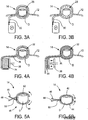
- the catalyst device 14 can assume many different forms. Exemplary alternative embodiments of the catalyst device 14 will now be described by reference to Figures 3A-12 .
- the catalyst device 14 may comprise an inflatable member or bladder 28 which, when inflated, exerts pressure circumferentially about the digit D.
- the bladder 28 is connected to a pump P by a supply line 30.
- the pump P feeds air into the interior of the bladder 28 via the supply line 30 thereby inflating the bladder, as illustrated in Figure 3B .
- the supply line 30 may be vented thereby enabling the bladder 28 to be deflated after body fluid has been sampled.
- the pump P may be reversible, thereby enabling deflation of the bladder 28.
- the catalyst device 14 can comprise an alternative inflatable bladder construction.
- the catalyst device 14 can comprise an inflatable bladder 32 which is connected to a fluid-filled flexible chamber 34 via a feed line 36.
- the fluid may be noncompressible.
- the fluid can be forced into the interior of the inflatable bladder 32 by any suitable mechanism.
- the flexible chamber 34 is compressed by a movable piston 38, thereby forcing the fluid out of the flexible chamber 34 through the feed line 36 and into the interior of the inflatable bladder 32.
- the piston 38 can be driven by any suitable mechanism or arrangement.
- the piston 38 can be driven by solenoid, motor, and/or cam arrangement. The specifics of the driving mechanism for the piston 38 being well within the capabilities of those ordinary skill in the art.
- the embodiment depicted in Figures 4A-4B is constructed to exert a circumferential pressure about the digit D.
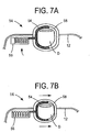
- the catalyst device 14 can comprise a user-controlled spring clip 40.
- the clip 40 can comprise first and second arms 42,44 that are configured to substantially surround the digit D.
- the clip 40 further comprises first and second end portions 46,48 which are graspable by the user.
- the clip 40 is biased by a spring 50 such that it is closed in its normal state. The user grasps the end portions 46 and 48 pressing them together to open the arms 42,44 of the clip 40 and insert the digit D therein. Then, the user releases the end portions 46,48 and the bias provided by the spring 50 acts to close the arms 42,44 around the inserted digit D.
- the spring clip 40 thus exerts a circumferential, or substantially circumferential pressure about the digit D.
- the catalyst device 14 comprises a cable or strap 52 which is attached at one end thereof to a motor M.
- the motor M is constructed to wind the cable or strap 52 thereby drawing a certain length of the cable or strap 52 about the wound end portion thereof, thus constricting the cable or strap 52 about the digit D.
- the motor M can be driven by any suitable mechanism, such as a solenoid or spring-loaded mechanism. The specifics of the drive mechanism and the motor M being well within the capabilities of those ordinary skill in the art. Thus, according to this arrangement, circumferential pressure is applied about the digit D.
- FIGS 7A-7B illustrate yet another alternative construction for the catalyst device 14.
- the pressing member 56 can comprise any suitable configuration.
- the pressing member 56 can be in the form of a compression spring, per the illustrated embodiment.
- the pressing member 56 can be in the form of the movable fluid or mechanical piston-type arrangement, the specifics of which being well within the capabilities of those ordinary skill in the art.
- the pusher arm 54 is driven into the digit D by the pressing member 56, and in cooperation with a relatively rigid digit housing member 58, creates pressure about the digit D. This pressure is not totally circumferential, but can be characterized as "substantially circumferential.”
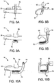
- the catalyst device 14 is embodied by a cinchable strap arrangement, as illustrated in Figures 8A-8B .
- a strap 60 forms a loop 61 through which a digit D is inserted.
- the cinchable strap 60 is retained in its operative position with the assistance of a strap housing 62.
- the strap 60 comprises a free end 64 which passes through an opening or slot 66.
- the free end 64 is drawn through the slot 66 by a suitable mechanism. Suitable mechanisms include manually pulling the free end 64, or mechanically drawing the free end 64 by suitable arrangements such as a motor, cam, or spring-loaded device of the type previously described herein.
- the strap 60 is preferably formed from a material which facilitates cleaning thereof any event that body fluid comes into contact with the strap 60 during the sampling procedure.
- the strap 60 can be formed of a nonporous thermoplastic material to facilitate cleaning.
- the cinching of the strap about the digit D acts to apply circumferential or substantially circumferential pressure thereto.
- the catalyst device 14 can comprise an open jaw 68 through which a digit D is inserted.
- the jaw 68 comprises an interior portion which is roughly shaped correspond to the circumference of the digit D.
- the dimensions of the interior portion of the jaw 68 are large enough to accommodate most digits therein without significant interference.
- Disposed within the inner portion of the jaw 68 is an inflatable bladder or pillow 70.
- the interior of the inflatable pillow 70 is in fluid communication with the pump P through a feed line 72.
- the pump P is operable to force air into the interior of the inflatable pillow 70 via the feed line 72.
- the feed line 72 can be vented to permit deflation of the inflatable pillow 70.
- the pump P can be reversible thereby providing an alternative mechanism for deflating the pillow 70.
- the digit D is forced with a certain degree of pressure into opposing walls of the interior portion of the jaw 68.
- substantially circumferential pressure is applied to the digit D, thereby facilitating the expression of body fluid therefrom.
- the catalyst device 14 is in the form of what can be described in general as a closed jaw 74.
- the closed jaw 74 comprises a movable arm 76 which is connected to a frame 78 via a spring-loaded hinge 80.
- the arm 76 can be swung open to permit the introduction of the digit D therein.
- the hinge is biased to normally close the movable arm 76.
- An inflatable pillow 82 is disposed on the movable arm 76, and is connected to a pump P by a connection line 84.
- the connection line 84 can be vented, thereby allowing the pillow 82 to be deflated.
- the pump P can be reversible, thereby providing an alternative mechanism by which the pillow 82 can be deflated.
- the pillow 82 is inflated, the digit D is forced into opposing surfaces in the interior of the closed jaw 74 thereby creating the desired pressure.
- the closed nature of the jaw 74 of this particular embodiment can act to provide pressure around a greater degree of the circumference of the digit D as compared to the previously described embodiment.
- the catalyst device is in the form of a U-shaped channel 86 comprising first and second arms 88,90.
- the user places a digit D between the first and second arms 88 and 90, then draws the digit D back in the direction of the arrows A until the tip-region of the digit is properly located for sampling to occur (e.g., disposed upon the footprint 20).
- the first and second arms 88, 90 are flexible, and the distance 92 between the first and second arms 88, 90 is such that there is a significant amount of interference between the digit D and the first and second arms 88, 90 as the digit D is pulled back through the U-shaped channel 86.
- This interference creates the desired pressure upon the digit D at a location proximate to the tip region thereof from which to sample body fluid is to be expressed.
- the arrangement instead of having the user move the digit D manually through to U-shaped channel, the arrangement can comprise a mechanism for moving the U-shaped channel told to do the digit D. Such a construction as illustrated in Figure 12 .
- the U-shaped channel is attached to a motor M via an appropriate mechanical linkage 94.
- the motor M drives the linkage 94, and the attached U-shaped member 86, in the direction of arrow A.
- the linkage 94 and the attached U-shaped member 86 is driven back in the opposite direction.
- the driving mechanism is not limited to the illustrated example, and can take on any suitable form.
- the driving mechanism can comprise a solenoid, spring driven mechanism, or other system known to produce a linear motion. The particulars of the driving mechanism being well within the capabilities of those ordinary skill in the art.
- the U-shaped member has first and second arms 86,88 with a distance 92 between them which creates an interference with the digit D when moved in the direction of arrow A.
- the pressure created on the digit D according to these configurations can be described as "substantially" circumferential pressure.
- the above-described catalyst devices can form at least part of an integrated device.
- integrated device or “integrated meter” means a device or meter that includes all components necessary to perform sampling of the body fluid, transport of the body fluid, quantification of an analyte, and display of the amount of analyte contained in the sample body fluid.
- an integrated device or meter can comprise one or more, or any combination, of the features previously described herein.
- integrated meter or device can comprise additional components and/or features, which are described as follows.
- the integrated meter 100 generally comprises a housing 112 and a catalyst device 114.
- the catalyst device 114 may take any suitable form.
- the catalyst device 114 may comprise a cuff 116 attached to the housing 112 via a mount 118.
- the catalyst device 114 can comprise any of the previously described alternative catalyst device configurations.
- the integrated meter 100 may further comprise a footprint 120 of the type previously described.
- a door 123 can be provided on the housing 112. The door 123 is connected via a hinge 125 to the housing 112. As described in further detail below, the door 123 can be opened to reveal a cartridge containing a plurality of skin-piercing elements.
- the integrated meter 100 further includes a display 127 for communicating the results of the analysis on the sample body fluid for the presence and/or concentration of an analyte contained therein.
- the integrated meter 100 may further include one or more buttons 129 which can be pressed by the user to engage various functions and interfaces of the integrated meter 100.
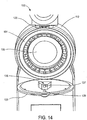
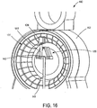
- FIG 14 is an illustration of the integrated meter 100 with the door 123 opened to reveal further details of the interior components of the integrated meter 100.
- the housing 112 contains a cartridge 131 therein.
- the cartridge 131 is circular and contains a plurality of skin-piercing elements as further described herein.
- the cartridge 131 is mounted about a hub 133 and is rotatable. Thus, upon sampling a skin-piercing element is driven through an opening in the housing in registry with the footprint 120 and pierces the skin of the user. Once the test has been completed, the cartridge 131 can be rotated such that an unused skin-piercing element now comes into registry with the opening in the housing and the corresponding opening in the footprint 120 in preparation for the next sampling event.
- the present invention is not limited to the illustrated circular cartridge having the particular configuration depicted in the drawing figures. To the contrary, a number of alternative cartridge configurations are possible, such as a slidable linear or polygonal configuration (not shown). Also illustrated in Figure 14 is the presence of a light source 139 disposed on the back of the door 123.
- the light source 139 can take any suitable form, such as a light emitting diode. It should be understood that alternative light sources may also be utilized. The function of the light source 139 will be described in further detail below.
- the replaceable cartridge 131 generally may comprise a plurality of compartments defining a plurality of body fluid sampling and analysis sites 132. Contained in each sampling and analysis site 132 is a skin penetration member 122.
- Each skin penetration member 122 can take any suitable form. According to the illustrated embodiment, each skin penetration member 122 is in the form of a hollow needle. It should be understood that alternative skin penetration members may also be utilized consistent with the principles of the present invention (e.g., solid lancets, etc.) each skin-penetration member can be attached to a needle hub 124.
- Each needle hub 124 is, in turn, attached to an actuation element 126.
- the actuation elements can be mechanical, electrical, pneumatic, etc.
- the actuation element 126 is in the form of a torsional spring. Upon activation, the torsional spring drives the needle hub 124 and the attached skin penetration member 122 into the skin of the user disposed on the footprint 120.
- each sampling/analysis site 132 further contains a signaling mechanism which produces a detectable signal when contacted with a target analyte contained in a sample of body fluid expressed from the skin of a digit D. A number of suitable mechanisms are envisioned.
- each needle hub 124 contains a reagent pad 129 which generally comprises an absorbent material containing a chemical reagent which, upon reaction with a target analyte, produces a chemical reaction that results in a detectable signal.
- the reagent pad 129 is in fluid communication with the inner bore of the skin piercing element 122.
- the signal can be detected optically, electrochemically, or by other suitable means.
- the reagent pad 129 upon reaction with the target analyte, produces a spot which is optically detected by the optical assembly 135 in a manner known to those skilled in the art.
- the spot produced by the above-mentioned reaction can be observed optically through a window 143 formed along the interior region of the illustrated cartridge 131 by the optical assembly 135.
- light emitted from the light source 139 is incident upon the reagent pad 129, and reflects off the surface thereof.
- the amount of light reflected off the reaction spot differs from the light reflected off of other portions of the reagent pad 129 containing no such reaction spot.
- This reflected light is picked up by the optical assembly, first through the lens 137 ( Figure 14 ), and eventually is incident upon an optical detector element 142 ( Figure 16 ).
- the optical detector element 142 generally comprises one or more detector elements. According to one alternative construction, the detector element 142 comprises a plurality of detector elements formed in an array.
- the array can take any suitable configuration, and can be a linear array according to one nonlimiting example.
- the detector elements can comprise any suitable construction.
- the detector elements 142 can comprise a photo diode, CCD, or CMOS based detector element.
- the signals transmitted to the detector element 142 are passed on to suitable electronics contained within the housing 112 (see, e.g., Figure 17 ) via suitable electrical connectors, such as flexible ribbons 141.
- suitable electrical connectors such as flexible ribbons 141.
- FIG. 17 Additional components of an integrated meter 100 are illustrated in Figure 17 .
- the view depicted in Figure 17 is that of an integrated meter 100 with the back panel removed to reveal the above-referenced additional components.
- the integrated meter 100 may further include a plurality of rollers 147 which cooperate with the cartridge 131 and a motor drive 149 thereby enabling the rotation of the cartridge 131 about the hub 133, and indexing of the analysis sites 132 with the footprint 120.
- the integrated meter 100 may also include a pressure pump 151 which, according to certain embodiments, comprises a pump capable of producing both positive and negative pressures.
- the pump 151 can create a positive pressure within the cuff 116, as previously discussed.
- the pump 151 can create a negative or vacuum pressure at the surface of the skin located over the footprint 120.
- the integrated meter 100 may further include appropriate electronics, as embodied in the circuit board 153 of the illustrated embodiment.
- the circuit board contains conventional electronic components capable of controlling the various functions of the integrated meter 100 in the desired manner.
- the integrated meter 100 may further comprise a suitable power supply 155, such as the illustrated batteries.
- the embodiment of the integrated meter 100 illustrated in Figures 13-17 includes a catalyst device 114 in the form of the cuff 116 which is fixedly mounted to the housing 112 via mount 118. Due to this construction, the integrated meter 100 is suitable for digital testing (e.g., finger testing).
- a modified form of the integrated meter 100 is illustrated in Figure 18 .
- the integrated meter 200 comprises a housing 212 which a shaped and contoured to conform to the grip of a user.
- the housing 212 includes a plurality of recesses 213 which are shaped in contoured to be grasped by the fingers, as well as a contoured rear surface 215 which is shaped to conform to surfaces of the palm and thumb of the user.
- the integrated meter 200 comprises a catalyst device 214 comprising, at least in part, passageway sized and configured to permit the insertion of a digit D therein.
- the catalyst device 214 can have a construction of any of the types of catalyst device as previously described herein.
- the catalyst device 214 comprises an inflatable bladder or cuff 216.
- the cuff 216 is structured and operates in the same manner previously described herein.
- the integrated meter 200 further comprises a suitable display 227 which communicates the results of the analysis to the user.
- the integrated meter 200 further contains at least one skin piercing element 222.
- a plurality of skin piercing elements 222 are contained within the housing 212.
- a plurality of skin piercing elements 222 are provided in the form of the replaceable cartridge 231 having the same construction as the previously described cartridge.
- the catalyst device 214 has a mode of operation which can be characterized as automatic, or semiautomatic.
- the catalyst device 214 can be activated manually by the user by pressing a button B, which initiates the catalyst as well as further operation of the device, as previously described herein.
- one or more sensors are provided in the integrated meter 200 that function to determine when a digit D is properly positioned and ready for sampling to begin. Upon detection of this state, the catalyst as well as further operations of the device are automatically initiated.
- the integrated meter 200 may also have any one or combination of features described as being associated with integrated meter 100.
- the integrated meter 300 generally comprises a housing 312, a catalyst device 314 in the form of an inflatable bladder or cuff 316.
- the cuff 316 is attached to the housing 312 in a movable manner via a hinge 318.
- a footprint 320 is provided on the exterior of the housing 312 which is adapted to receive a digit thereon prior to commencement of the sampling and analysis procedure.
- the integrated meter 300 may further comprise a disposable cartridge 331, as well as a pump 351 having both positive and negative pressure feed lines 330,332, respectively.
- the cuff 316 When it is desired to use the device for digital body fluid sampling and analysis, the cuff 316 is folded upwardly to the position illustrated in Figure 19A whereby a digit can be inserted there through and placed over the footprint 320 in a manner previously described herein.
- the integrated meter 300 can be used for alternate site body fluid sampling and analysis.
- the cuff 316 can be folded back and received within a recess 334 formed in the housing 312 of the integrated meter 300.
- the meter 300 can be grasped and applied to an alternate site by pressing the footprint 320 directly to the skin of the user at the desired location for alternate site body fluid sampling and analysis.
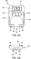
- an integrated meter 400 can be constructed as illustrated in Figures 20A-20B .
- the integrated meter 400 generally includes a housing 412, and a catalyst device 414, which may be in the form of an inflatable bladder or cuff 416, a display 427 and a disposable cartridge 431, all constructed as previously described herein.
- the cuff 416 is connected to a frame 417 via a pivotable hinge or connector 419.
- the footprint 420 may be connected to the frame 417, instead of directly connected to the housing 412.
- the frame 417 is connected to the housing 412 via a second pivotable connection 419. This the second pivotable connection 419 allows the frame 417, and the cuff 416 attached thereto, to be rotated in the manner indicated at arrow R.
- This pivotable connection 419 allows the cuff 416 to be repositioned on the opposite side of the device, as indicated by the broken lines appearing in Figure 20A , thereby facilitating either right-handed or left-handed testing by the user.
- the cuff 416 is positioned as illustrated in Figure 20A when it is desired to use the device for digital body fluid sampling and analysis.
- the cuff 416 can be folded back and received within a recess 434 formed in the frame 427, as illustrated in Figure 20B .
- the integrated meter 400 and make include a feature which senses that the device is being used for alternate site testing (e.g., sensors that detect when the cuff 46 has been folded back and received within a recess 434), and then inverts the output on the display 417 so as to facilitate reading the results of the analysis when the integrated meter is oriented in a manner depicted in Figure 20B .
- a feature which senses that the device is being used for alternate site testing e.g., sensors that detect when the cuff 46 has been folded back and received within a recess 434
- inverts the output on the display 417 so as to facilitate reading the results of the analysis when the integrated meter is oriented in a manner depicted in Figure 20B .
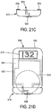
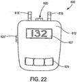
- Figures 21A-21D illustrate a further alternative embodiment constructed according to the present invention.
- the integrated device 500 is composed of at least two separate components, a main component ( Figure 21A ) and one or more attachments ( Figures 21B , 21C ).
- the integrated meter 500 generally comprises a housing 512, a display 527, one or more buttons 529, and a disposable cartridge 531, all constructed as previously described herein.
- the integrated meter 500 further comprises a pressure pump 551 which is connected to a positive feed line 530, as well as a negative pressure feed line 532.
- the positive pressure feed line 530 terminates in a female coupling 541.
- the negative pressure feed line 532 terminates in a female coupling 542.
- the couplings 541 and 542 can be structured such that they are normally sealed in a closed matter until a corresponding male member is inserted therein, thereby opening the normally closed end and enabling fluid communication with the pump 551.
- a first attachment 560 ( Figure 21B ) is constructed to permit digital body fluid sampling and analysis.
- the first attachment 560 comprises a plurality of pressure cuffs 516,516' fixedly mounted thereto. This construction facilitates either right or left-handed testing.
- the attachment 560 further comprises a footprint 520 constructed as previously described herein.
- a male connector 562 is also provided which provides for fluid communication with the interior of the cuffs 516,516'.
- the male connector 562 is configured for insertion into corresponding female connector 541 present in the main component of the arrangement.
- a plurality of electrical contacts 564 may also be provided on the attachment 560. These electrical contacts are configured to mate with corresponding electrical contacts 547,549 disposed on the main unit ( Figure 21A ).
- a signal is sent to the electronics contained in the integrated meter 500 that indicate that a digital sampling and analysis module is connected thereto. Based on the signal, various controls and signals can then be generated which tailor the functionality of the integrated meter 500 specifically for digital body fluid sampling and analysis.
- a solenoid or similar device can be used to open and close valves present in one or more of the feed lines 530, 532, thereby selectively applying positive pressure to the attachment, and more specifically, to the interior of the cuffs 516,516' connected thereto.
- a second attachment 570 can be provided which is constructed for alternate site body fluid sampling and analysis.
- the second attachment 570 generally comprises a footprint 520 disposed on the bottom surface thereof.
- the second attachment 570 further comprises a male connector 572 which is configured for mating with the corresponding female connector 542 present in the main unit ( Figure 21A ), thereby enabling pressure communication with the pump 551. More specifically, the connection between a male coupling 572 and a female coupling 542 enables a vacuum to be applied in the vicinity of the footprint 520 when placed against the skin of the user, thereby serving to act as a catalyst for the expression of body fluid at the sampling site.
- the attachment 570 also includes one or more electrical contacts 574 which are constructed and function in a manner similar to the electrical contacts 564 described in connection with the first attachment 560.
- Figure 21D illustrates an integrated meter 500 having the second attachment 570 attached thereto, thereby rendering the device suitable for alternate site body fluid sampling and analysis.
- an integrated meter 600 can be constructed which is capable of both digital body fluid sampling and analysis, as well as alternate site body fluid sampling and analysis, without the use of attachments.
- the integrated meter 600 generally comprises a housing 612, and one or more cuffs 616,616' securely attached thereto. This construction facilitates digital body fluid sampling and analysis from either the right or left hand of the user.
- the integrated meter 600 may also include a display 627 and one or more buttons 629, as well as any of the other previously described features or alternative constructions set forth previously herein.
- the integrated meter 600 further includes a first of footprint 620 which is provided for digital body fluid sampling and analysis.
- the integrated meter 600 further includes at least one additional footprint 620' which is located at a position on the integrated meter 600 which allows easy access thereto for positioning the meter 600 and sampling body fluid at an alternate site. It should be understood that the positioning of the footprints 620,620' is not limited to the arrangement depicted in the illustrated embodiment.
- the footprint 620 and/or footprint 620' can be disposed on any suitable face, at any suitable location, on the integrated meter 600 so long as the functionality of providing for both digital and alternate site body fluid sampling analysis can be provided.
- the integrated meter 700 generally comprises a housing 712, a display 717, a footprint 720, one or more buttons 729, and a catalyst device 714 in the form of a retractable cuff 716.
- the cuff 716 maybe formed in any suitable manner and may take any of the alternative constructions described previously.
- the integrated meter 700 comprise any one or more, or combinations of features previously described its association with the other embodiments.
- the cuff 716 is tethered to the integrated meter 700 via a pressure delivery tube/cable assembly 730.
- the pressure delivery tube/cable assembly 730 generally comprises a hollow tubular member 731 which can deliver pressurized air to the cuff 716, as well as a concentrically located cable 732, which adds strength to the assembly thereby enabling retraction and removal of the cuff 716.
- the pressure to delivery tube/cable assembly 730 is not limited to the illustrated embodiment, but can take on further alternative constructions so long as the desired functionality is maintained.
- a digit When pulled out into the position illustrated in Figure 23A , a digit can be inserted through the cuff 716 and placed over the footprint 720 in a manner previously described herein, thus enabling digital body fluid sampling and analysis.
- the cuff 716 can be retracted via a tensioning device 736 having a conventional construction. Upon retraction, the cuff 716 is received within a similarly shaped recess 742 which is formed in a housing 712.
- the majority of the cuff 716 is received within the recess 742, however, a small portion remains outside the recess such that it can be easily grasped by the user and withdrawn for use in digital body fluid sampling and analysis.
- a user loads a fresh disposable cartridge containing a plurality of skin penetration members and analysis sites into an integrated meter.
- the integrated meter then reads calibration data contained in or on the cartridge. This data can be read in any suitable manner. For example, a bar code may be placed on the cartridge which can be optically read by the optical assembly contained within the meter.
- the integrated meter selects the proper lookup table or algorithm to calculate an aggregate glucose measurement taking into consideration the calibration data.
- the meter may then place itself in a ready mode waiting for a trigger to initiate sampling and testing. The user then either manually presses a button or trigger to initiate sampling and analysis, or the device verifies that it is properly positioned on the skin of the user and ready to begin the sampling and analysis procedure.
- Suitable sensors to accomplish this include optical, capacitive or pressure sensors.
- the device then initiates a catalyst which acts to facilitate the expression of body fluid.
- the catalyst is an inflatable member that exerts pressure on a digit.
- the catalyst is vacuum pressure which generates suction at the sampling site. Sensors present in the meter may be used to monitor and control the positive or negative pressure of the catalyst.
- the skin penetration member e.g., a hollow needle
- the skin penetration member is actuated and driven into the skin of the user to create a wound site.
- the skin penetration member comes to rest in or directly on the wound created at the sampling site where it is in the desired position for collecting a sample of body fluid expressed from the wound.
- the integrated meter may further include a mechanism for detecting a whether a sufficient amount of sample has been expressed. Details of such suitable detection techniques are described in detail in U.S. Patent No. 7,052,652 , entitled ANALYTE CONCENTRATION DETECTION DEVICES AND METHODS .
- the catalyst is deactivated.
- a sample of body fluid is in fluid communication with a device or mechanism which creates a detectable signal upon reaction within analyte present in the sample body fluid.
- a device or mechanism which creates a detectable signal upon reaction within analyte present in the sample body fluid.
- one such suitable mechanism is a absorbent pad containing a chemical reagent which, upon reaction with the analyte produces a reaction spot which can be optically detected.
- An optical assembly which is an optical communication with the above described signal generating mechanism is utilized to detect the signal created via reaction with the analyte and communicate the signals to supporting electronics contained within the meter.
- concentration of a target analyte e.g., glucose
- concentration of a target analyte can then be calculated using these signals as a basis. Additional factors may be considered during these calculations, such as the sample size, levels of other substances contained in the sample (e.g. hematocrit), etc.
- Such optional calculation techniques are described in further detail in U.S. Patent Application Serial No. 11/239,122 , entitled ANALYTE DETECTION DEVICES AND METHODS WITH HEMATOCRIT/VOLUME CORRECTION AD FEEDBACK CONTROL .
Landscapes
- Health & Medical Sciences (AREA)
- Life Sciences & Earth Sciences (AREA)
- Physics & Mathematics (AREA)
- Molecular Biology (AREA)
- Animal Behavior & Ethology (AREA)
- Pathology (AREA)
- Engineering & Computer Science (AREA)
- Biomedical Technology (AREA)
- Heart & Thoracic Surgery (AREA)
- Medical Informatics (AREA)
- Hematology (AREA)
- Surgery (AREA)
- Biophysics (AREA)
- General Health & Medical Sciences (AREA)
- Public Health (AREA)
- Veterinary Medicine (AREA)
- Dermatology (AREA)
- Pain & Pain Management (AREA)
- Vascular Medicine (AREA)
- Geometry (AREA)
- Measurement Of The Respiration, Hearing Ability, Form, And Blood Characteristics Of Living Organisms (AREA)
- Sampling And Sample Adjustment (AREA)
Applications Claiming Priority (2)
| Application Number | Priority Date | Filing Date | Title |
|---|---|---|---|
| US11/510,784 US8372015B2 (en) | 2006-08-28 | 2006-08-28 | Body fluid sampling device with pivotable catalyst member |
| PCT/US2007/018780 WO2008027319A2 (en) | 2006-08-28 | 2007-08-27 | Body fluid monitoring and sampling devices and methods |
Publications (3)
| Publication Number | Publication Date |
|---|---|
| EP2061375A2 EP2061375A2 (en) | 2009-05-27 |
| EP2061375A4 EP2061375A4 (en) | 2011-07-06 |
| EP2061375B1 true EP2061375B1 (en) | 2018-04-11 |
Family
ID=39136508
Family Applications (1)
| Application Number | Title | Priority Date | Filing Date |
|---|---|---|---|
| EP07837337.0A Active EP2061375B1 (en) | 2006-08-28 | 2007-08-27 | Body fluid monitoring and sampling devices |
Country Status (5)
| Country | Link |
|---|---|
| US (2) | US8372015B2 (enExample) |
| EP (1) | EP2061375B1 (enExample) |
| JP (1) | JP2010502278A (enExample) |
| CA (1) | CA2661919A1 (enExample) |
| WO (1) | WO2008027319A2 (enExample) |
Families Citing this family (115)
| Publication number | Priority date | Publication date | Assignee | Title |
|---|---|---|---|---|
| US6391005B1 (en) | 1998-03-30 | 2002-05-21 | Agilent Technologies, Inc. | Apparatus and method for penetration with shaft having a sensor for sensing penetration depth |
| US8641644B2 (en) | 2000-11-21 | 2014-02-04 | Sanofi-Aventis Deutschland Gmbh | Blood testing apparatus having a rotatable cartridge with multiple lancing elements and testing means |
| AU2002348683A1 (en) | 2001-06-12 | 2002-12-23 | Pelikan Technologies, Inc. | Method and apparatus for lancet launching device integrated onto a blood-sampling cartridge |
| US9427532B2 (en) | 2001-06-12 | 2016-08-30 | Sanofi-Aventis Deutschland Gmbh | Tissue penetration device |
| US7344507B2 (en) | 2002-04-19 | 2008-03-18 | Pelikan Technologies, Inc. | Method and apparatus for lancet actuation |
| EP1404233B1 (en) | 2001-06-12 | 2009-12-02 | Pelikan Technologies Inc. | Self optimizing lancing device with adaptation means to temporal variations in cutaneous properties |
| US8337419B2 (en) | 2002-04-19 | 2012-12-25 | Sanofi-Aventis Deutschland Gmbh | Tissue penetration device |
| US7041068B2 (en) | 2001-06-12 | 2006-05-09 | Pelikan Technologies, Inc. | Sampling module device and method |
| CA2448790C (en) | 2001-06-12 | 2010-09-07 | Pelikan Technologies, Inc. | Electric lancet actuator |
| US9795747B2 (en) | 2010-06-02 | 2017-10-24 | Sanofi-Aventis Deutschland Gmbh | Methods and apparatus for lancet actuation |
| US7981056B2 (en) | 2002-04-19 | 2011-07-19 | Pelikan Technologies, Inc. | Methods and apparatus for lancet actuation |
| US9226699B2 (en) | 2002-04-19 | 2016-01-05 | Sanofi-Aventis Deutschland Gmbh | Body fluid sampling module with a continuous compression tissue interface surface |
| US7004928B2 (en) | 2002-02-08 | 2006-02-28 | Rosedale Medical, Inc. | Autonomous, ambulatory analyte monitor or drug delivery device |
| US7232451B2 (en) | 2002-04-19 | 2007-06-19 | Pelikan Technologies, Inc. | Method and apparatus for penetrating tissue |
| US8360992B2 (en) | 2002-04-19 | 2013-01-29 | Sanofi-Aventis Deutschland Gmbh | Method and apparatus for penetrating tissue |
| US7491178B2 (en) | 2002-04-19 | 2009-02-17 | Pelikan Technologies, Inc. | Method and apparatus for penetrating tissue |
| US8784335B2 (en) | 2002-04-19 | 2014-07-22 | Sanofi-Aventis Deutschland Gmbh | Body fluid sampling device with a capacitive sensor |
| US8267870B2 (en) | 2002-04-19 | 2012-09-18 | Sanofi-Aventis Deutschland Gmbh | Method and apparatus for body fluid sampling with hybrid actuation |
| US7297122B2 (en) | 2002-04-19 | 2007-11-20 | Pelikan Technologies, Inc. | Method and apparatus for penetrating tissue |
| US7229458B2 (en) | 2002-04-19 | 2007-06-12 | Pelikan Technologies, Inc. | Method and apparatus for penetrating tissue |
| US8221334B2 (en) | 2002-04-19 | 2012-07-17 | Sanofi-Aventis Deutschland Gmbh | Method and apparatus for penetrating tissue |
| US7226461B2 (en) | 2002-04-19 | 2007-06-05 | Pelikan Technologies, Inc. | Method and apparatus for a multi-use body fluid sampling device with sterility barrier release |
| US9314194B2 (en) | 2002-04-19 | 2016-04-19 | Sanofi-Aventis Deutschland Gmbh | Tissue penetration device |
| US9795334B2 (en) | 2002-04-19 | 2017-10-24 | Sanofi-Aventis Deutschland Gmbh | Method and apparatus for penetrating tissue |
| US7892183B2 (en) | 2002-04-19 | 2011-02-22 | Pelikan Technologies, Inc. | Method and apparatus for body fluid sampling and analyte sensing |
| US8702624B2 (en) | 2006-09-29 | 2014-04-22 | Sanofi-Aventis Deutschland Gmbh | Analyte measurement device with a single shot actuator |
| US7547287B2 (en) | 2002-04-19 | 2009-06-16 | Pelikan Technologies, Inc. | Method and apparatus for penetrating tissue |
| US7901362B2 (en) | 2002-04-19 | 2011-03-08 | Pelikan Technologies, Inc. | Method and apparatus for penetrating tissue |
| US7909778B2 (en) | 2002-04-19 | 2011-03-22 | Pelikan Technologies, Inc. | Method and apparatus for penetrating tissue |
| US7674232B2 (en) | 2002-04-19 | 2010-03-09 | Pelikan Technologies, Inc. | Method and apparatus for penetrating tissue |
| US8579831B2 (en) | 2002-04-19 | 2013-11-12 | Sanofi-Aventis Deutschland Gmbh | Method and apparatus for penetrating tissue |
| US7331931B2 (en) | 2002-04-19 | 2008-02-19 | Pelikan Technologies, Inc. | Method and apparatus for penetrating tissue |
| US9248267B2 (en) | 2002-04-19 | 2016-02-02 | Sanofi-Aventis Deustchland Gmbh | Tissue penetration device |
| US7976476B2 (en) | 2002-04-19 | 2011-07-12 | Pelikan Technologies, Inc. | Device and method for variable speed lancet |
| US7892185B2 (en) | 2002-04-19 | 2011-02-22 | Pelikan Technologies, Inc. | Method and apparatus for body fluid sampling and analyte sensing |
| US8574895B2 (en) | 2002-12-30 | 2013-11-05 | Sanofi-Aventis Deutschland Gmbh | Method and apparatus using optical techniques to measure analyte levels |
| US7052652B2 (en) | 2003-03-24 | 2006-05-30 | Rosedale Medical, Inc. | Analyte concentration detection devices and methods |
| WO2004107975A2 (en) | 2003-05-30 | 2004-12-16 | Pelikan Technologies, Inc. | Method and apparatus for fluid injection |
| WO2004107964A2 (en) | 2003-06-06 | 2004-12-16 | Pelikan Technologies, Inc. | Blood harvesting device with electronic control |
| WO2006001797A1 (en) | 2004-06-14 | 2006-01-05 | Pelikan Technologies, Inc. | Low pain penetrating |
| US8282576B2 (en) | 2003-09-29 | 2012-10-09 | Sanofi-Aventis Deutschland Gmbh | Method and apparatus for an improved sample capture device |
| WO2005037095A1 (en) | 2003-10-14 | 2005-04-28 | Pelikan Technologies, Inc. | Method and apparatus for a variable user interface |
| US7822454B1 (en) | 2005-01-03 | 2010-10-26 | Pelikan Technologies, Inc. | Fluid sampling device with improved analyte detecting member configuration |
| WO2005065414A2 (en) | 2003-12-31 | 2005-07-21 | Pelikan Technologies, Inc. | Method and apparatus for improving fluidic flow and sample capture |
| WO2006011062A2 (en) | 2004-05-20 | 2006-02-02 | Albatros Technologies Gmbh & Co. Kg | Printable hydrogel for biosensors |
| WO2005120365A1 (en) | 2004-06-03 | 2005-12-22 | Pelikan Technologies, Inc. | Method and apparatus for a fluid sampling device |
| US9775553B2 (en) | 2004-06-03 | 2017-10-03 | Sanofi-Aventis Deutschland Gmbh | Method and apparatus for a fluid sampling device |
| US20100331646A1 (en) * | 2009-06-30 | 2010-12-30 | Abbott Diabetes Care Inc. | Health Management Devices and Methods |
| US9636450B2 (en) * | 2007-02-19 | 2017-05-02 | Udo Hoss | Pump system modular components for delivering medication and analyte sensing at seperate insertion sites |
| US8652831B2 (en) | 2004-12-30 | 2014-02-18 | Sanofi-Aventis Deutschland Gmbh | Method and apparatus for analyte measurement test time |
| US8956291B2 (en) | 2005-02-22 | 2015-02-17 | Admetsys Corporation | Balanced physiological monitoring and treatment system |
| US20060281187A1 (en) | 2005-06-13 | 2006-12-14 | Rosedale Medical, Inc. | Analyte detection devices and methods with hematocrit/volume correction and feedback control |
| US8801631B2 (en) | 2005-09-30 | 2014-08-12 | Intuity Medical, Inc. | Devices and methods for facilitating fluid transport |
| EP1928316B1 (en) | 2005-09-30 | 2014-02-26 | Intuity Medical, Inc. | Multi-site body fluid sampling and analysis cartridge |
| US8880138B2 (en) * | 2005-09-30 | 2014-11-04 | Abbott Diabetes Care Inc. | Device for channeling fluid and methods of use |
| US7826879B2 (en) | 2006-02-28 | 2010-11-02 | Abbott Diabetes Care Inc. | Analyte sensors and methods of use |
| US7993275B2 (en) * | 2006-05-25 | 2011-08-09 | Sotera Wireless, Inc. | Bilateral device, system and method for monitoring vital signs |
| CN101500476A (zh) * | 2006-07-06 | 2009-08-05 | 雷比德克斯有限公司 | 综合血液取样和检验设备及其使用方法 |
| US12245852B2 (en) | 2007-06-12 | 2025-03-11 | Sotera Wireless, Inc. | Optical sensors for use in vital sign monitoring |
| US20100130875A1 (en) * | 2008-06-18 | 2010-05-27 | Triage Wireless, Inc. | Body-worn system for measuring blood pressure |
| JP4625062B2 (ja) * | 2007-08-31 | 2011-02-02 | テルモ株式会社 | 補助具 |
| US20090118628A1 (en) * | 2007-11-01 | 2009-05-07 | Triage Wireless, Inc. | System for measuring blood pressure featuring a blood pressure cuff comprising size information |
| JP2011508872A (ja) * | 2007-12-10 | 2011-03-17 | バイエル・ヘルスケア・エルエルシー | 一体型の流体分析対象物測定システム |
| WO2009081405A2 (en) * | 2007-12-25 | 2009-07-02 | Rapidx Ltd. | Devices and methods for reduced-pain blood sampling |
| WO2009126900A1 (en) | 2008-04-11 | 2009-10-15 | Pelikan Technologies, Inc. | Method and apparatus for analyte detecting device |
| EP2293719B1 (en) | 2008-05-30 | 2015-09-09 | Intuity Medical, Inc. | Body fluid sampling device -- sampling site interface |
| EP2299904B1 (en) | 2008-06-06 | 2019-09-11 | Intuity Medical, Inc. | Medical measurement method |
| CA3095014A1 (en) | 2008-06-06 | 2009-12-10 | Intuity Medical, Inc. | Detection meter and mode of operation |
| WO2010009172A1 (en) | 2008-07-14 | 2010-01-21 | Abbott Diabetes Care Inc. | Closed loop control system interface and methods |
| WO2010011805A1 (en) * | 2008-07-24 | 2010-01-28 | Admetsys Corporation | Device and method for automatically sampling and measuring blood analytes |
| US8333715B1 (en) | 2008-10-07 | 2012-12-18 | Alferness Clifton A | Blood glucose sampling device |
| US9375169B2 (en) | 2009-01-30 | 2016-06-28 | Sanofi-Aventis Deutschland Gmbh | Cam drive for managing disposable penetrating member actions with a single motor and motor and control system |
| JP4885330B2 (ja) | 2009-02-18 | 2012-02-29 | パナソニック株式会社 | 穿刺器具、生体試料測定装置及び生体試料測定システム |
| US8864729B2 (en) | 2009-07-14 | 2014-10-21 | Stimatix Gi Ltd. | Ostomy closure |
| CN102469966B (zh) | 2009-07-23 | 2015-05-13 | 雅培糖尿病护理公司 | 持续分析物测量系统和用于植入它们的系统和方法 |
| US8919605B2 (en) | 2009-11-30 | 2014-12-30 | Intuity Medical, Inc. | Calibration material delivery devices and methods |
| US8965476B2 (en) | 2010-04-16 | 2015-02-24 | Sanofi-Aventis Deutschland Gmbh | Tissue penetration device |
| EP2584967B1 (en) * | 2010-06-24 | 2014-03-26 | Rapidx Ltd. | Device and system for blood sampling |
| CA2803797A1 (en) | 2010-06-25 | 2011-12-29 | Intuity Medical, Inc. | Analyte monitoring methods and systems |
| US20120065487A1 (en) * | 2010-09-07 | 2012-03-15 | Innova Medical Design LLC | Systems, methods, and devices for reducing the pain of glucose monitoring and insulin adminstration in diabetic patients |
| CA2843945C (en) | 2011-08-03 | 2022-06-21 | Intuity Medical, Inc. | Devices and methods for body fluid sampling and analysis |
| EP2846746B1 (en) | 2012-05-10 | 2022-03-09 | B.Braun Medical SAS | Ostomy appliance |
| BR112015028181A2 (pt) | 2013-05-09 | 2020-10-06 | Stimatix Gi Ltd | filtro e liberação de gás para aparelho de ostomia |
| EP3011544A4 (en) | 2013-06-21 | 2017-02-22 | Intuity Medical, Inc. | Analyte monitoring system with audible feedback |
| DE102013219432A1 (de) * | 2013-09-26 | 2015-03-26 | Peter Röhr | Blutentnahmevorrichtung und Verfahren zum Entnehmen von Blut |
| TWD172797S (zh) | 2013-10-31 | 2016-01-01 | 科萊恩製造(法國)公司 | 容器之部分 |
| USD796029S1 (en) | 2013-12-09 | 2017-08-29 | B. Braun Medical Sas | Colostomy appliance |
| USD783814S1 (en) * | 2013-12-09 | 2017-04-11 | B. Braun Medical Sas | Adapter for flatus release |
| USD766716S1 (en) | 2014-04-30 | 2016-09-20 | Clariant Production (France) Sas | Container |
| TWD172808S (zh) | 2014-11-27 | 2016-01-01 | Clariant Production France Sas | 容器 |
| USD766080S1 (en) * | 2015-02-26 | 2016-09-13 | Clariant Production (France) Sas | Container |
| US10722163B2 (en) * | 2015-03-31 | 2020-07-28 | Labrador Diagnostics Llc | Methods, devices, systems, and kits for automated blood collection by fingerstick |
| JP6558971B2 (ja) * | 2015-06-17 | 2019-08-14 | 株式会社日立ハイテクノロジーズ | 採血装置 |
| CN113751095B (zh) | 2015-12-11 | 2024-01-09 | 巴布森诊断公司 | 用于从全血分离血清或血浆的样品容器和方法 |
| US10136848B2 (en) * | 2016-05-20 | 2018-11-27 | Winnoz Technology, Inc. | Device and system of blood collection, and method thereof |
| CN106137223B (zh) * | 2016-08-12 | 2019-04-26 | 上海移宇科技股份有限公司 | 一步式全集成体液采样分析仪 |
| US11399755B2 (en) * | 2016-08-24 | 2022-08-02 | Becton, Dickinson And Company | Device for obtaining a blood sample |
| EP3538865A4 (en) | 2016-11-14 | 2019-12-25 | Siemens Healthcare Diagnostics Inc. | DEVICE FOR SAMPLING PREPARATION |
| EP3537973A4 (en) * | 2016-11-14 | 2019-09-18 | Siemens Healthcare Diagnostics Inc. | BLOOD DETECTION DEVICE WITH INTEGRATED ABSORBENT MATERIAL |
| USD824517S1 (en) | 2017-01-19 | 2018-07-31 | Stephen A. Young | Blood sampling device |
| US10791972B2 (en) | 2017-04-21 | 2020-10-06 | 2Pi-Sigma Corporation | Fluid measurement for automated medical sample collection and testing |
| US10928411B2 (en) | 2017-04-21 | 2021-02-23 | 2Pi-Sigma Corporation | Automated medical sample collection and testing |
| US11202593B2 (en) | 2017-04-21 | 2021-12-21 | 2Pi-Sigma Corp. | Adjustable lancet and test cartridge for automated medical sample collection and testing |
| US10816545B2 (en) | 2017-04-21 | 2020-10-27 | 2Pi-Sigma Corporation | Automated medical sample collection, testing, and analysis |
| US11103163B2 (en) | 2017-04-21 | 2021-08-31 | 2Pi-Sigma Corporation | Test cartridge and lancet for automated medical sample collection and testing |
| US11175303B2 (en) | 2017-04-21 | 2021-11-16 | 2Pi-Sigma Corp. | Automated medical sample collection and testing for providing blood coagulation indication |
| MX2020000114A (es) * | 2017-07-06 | 2020-08-06 | Becton Dickinson Co | Dispositivo de recoleccion de fluido biologico. |
| CN112437633A (zh) | 2018-05-25 | 2021-03-02 | 贝克顿·迪金森公司 | 带有振动模块的血液收集组件 |
| USD1012280S1 (en) | 2018-11-30 | 2024-01-23 | B. Braun Medical Sas | Ostomy device assembly |
| CN109662721B (zh) * | 2019-02-28 | 2024-02-02 | 吉林大学 | 全自动指尖采血用指侧推压器 |
| USD973876S1 (en) | 2020-03-18 | 2022-12-27 | Stephen A. Young | Blood sampling device |
| GB2598334B (en) * | 2020-08-26 | 2022-11-30 | Mowgli Innovations Ltd | Finger receptacle and holding device |
| US12050052B1 (en) | 2021-08-06 | 2024-07-30 | Babson Diagnostics, Inc. | Refrigerated carrier device for biological samples |
| EP4505185A1 (en) | 2022-04-06 | 2025-02-12 | Babson Diagnostics, Inc. | Automated centrifuge loader |
| US20240081703A1 (en) * | 2022-09-13 | 2024-03-14 | Health Made Easy | Blood collection devices and methods |
Citations (1)
| Publication number | Priority date | Publication date | Assignee | Title |
|---|---|---|---|---|
| WO2003066128A2 (en) * | 2002-02-08 | 2003-08-14 | Rosedale Medical, Inc. | Autonomous, ambulatory analyte monitor or drug delivery device |
Family Cites Families (51)
| Publication number | Priority date | Publication date | Assignee | Title |
|---|---|---|---|---|
| US3310002A (en) * | 1965-10-18 | 1967-03-21 | Robbin Lab Inc | Pipette pump |
| CH500707A (fr) * | 1968-07-26 | 1970-12-31 | Micromedic Systems Inc | Dispositif pour effectuer une prise de sang percutanée et digitale |
| DE3004011A1 (de) * | 1980-02-04 | 1981-08-13 | Philips Patentverwaltung Gmbh, 2000 Hamburg | Blutdruck-messvorrichtung |
| US4416279A (en) * | 1981-06-19 | 1983-11-22 | Lindner James A | Capillary blood sampling device |
| US4661319A (en) * | 1984-04-06 | 1987-04-28 | Boehringer Mannheim Diagnostics, Inc. | Blood transfer assembly |
| JPS63305841A (ja) | 1987-06-09 | 1988-12-13 | Omron Tateisi Electronics Co | 指用電子血圧計 |
| US5218966A (en) * | 1987-06-12 | 1993-06-15 | Omron Tateisi Electronics Co. | Electronic blood pressure meter |
| JPS63311930A (ja) * | 1987-06-12 | 1988-12-20 | Omron Tateisi Electronics Co | 指用電子血圧計 |
| DE4138702A1 (de) | 1991-03-22 | 1992-09-24 | Madaus Medizin Elektronik | Verfahren und vorrichtung zur diagnose und quantitativen analyse von apnoe und zur gleichzeitigen feststellung anderer erkrankungen |
| JP3605225B2 (ja) * | 1996-04-01 | 2004-12-22 | 大日本印刷株式会社 | 体液分析装置 |
| US6332871B1 (en) | 1996-05-17 | 2001-12-25 | Amira Medical | Blood and interstitial fluid sampling device |
| US7666150B2 (en) | 1996-05-17 | 2010-02-23 | Roche Diagnostics Operations, Inc. | Blood and interstitial fluid sampling device |
| JP3604808B2 (ja) * | 1996-05-28 | 2004-12-22 | 大日本印刷株式会社 | 体液分析装置 |
| JP3604812B2 (ja) * | 1996-06-21 | 2004-12-22 | 大日本印刷株式会社 | 体液分析装置 |
| JP3604819B2 (ja) | 1996-07-11 | 2004-12-22 | 大日本印刷株式会社 | 体液分析装置 |
| US6063039A (en) * | 1996-12-06 | 2000-05-16 | Abbott Laboratories | Method and apparatus for obtaining blood for diagnostic tests |
| US6706000B2 (en) * | 1997-11-21 | 2004-03-16 | Amira Medical | Methods and apparatus for expressing body fluid from an incision |
| JP2001017404A (ja) | 1999-07-09 | 2001-01-23 | Koike Medical:Kk | 医療用測定装置 |
| JP4210782B2 (ja) * | 1999-10-13 | 2009-01-21 | アークレイ株式会社 | 採血位置表示具 |
| US6706159B2 (en) * | 2000-03-02 | 2004-03-16 | Diabetes Diagnostics | Combined lancet and electrochemical analyte-testing apparatus |
| JP3834185B2 (ja) | 2000-05-01 | 2006-10-18 | テルモ株式会社 | 成分測定装置 |
| US7780610B2 (en) | 2000-05-01 | 2010-08-24 | Terumo Kabushiki Kaisha | Component measuring instrument and chip |
| DE10026172A1 (de) * | 2000-05-26 | 2001-11-29 | Roche Diagnostics Gmbh | System zur Entnahme von Körperflüssigkeit |
| DE10026170A1 (de) | 2000-05-26 | 2001-12-06 | Roche Diagnostics Gmbh | System zur Entnahme von Körperflüssigkeit |
| JP2002219115A (ja) * | 2001-01-26 | 2002-08-06 | Matsushita Electric Works Ltd | 採血装置 |
| JP2002219155A (ja) | 2001-01-29 | 2002-08-06 | Better Life Kk | エアーマッサージ装置 |
| US20030166264A1 (en) * | 2001-12-04 | 2003-09-04 | Dave Smith | Drug and alcohol assay assembly |
| US7141058B2 (en) * | 2002-04-19 | 2006-11-28 | Pelikan Technologies, Inc. | Method and apparatus for a body fluid sampling device using illumination |
| US7226461B2 (en) | 2002-04-19 | 2007-06-05 | Pelikan Technologies, Inc. | Method and apparatus for a multi-use body fluid sampling device with sterility barrier release |
| US7892183B2 (en) | 2002-04-19 | 2011-02-22 | Pelikan Technologies, Inc. | Method and apparatus for body fluid sampling and analyte sensing |
| US20030212344A1 (en) * | 2002-05-09 | 2003-11-13 | Vadim Yuzhakov | Physiological sample collection devices and methods of using the same |
| AU2003290589A1 (en) * | 2002-11-01 | 2004-06-07 | Pelikan Technologies, Inc. | Method and apparatus for body fluid sampling |
| US7572237B2 (en) | 2002-11-06 | 2009-08-11 | Abbott Diabetes Care Inc. | Automatic biological analyte testing meter with integrated lancing device and methods of use |
| JP2004208727A (ja) | 2002-12-26 | 2004-07-29 | Nishitomo:Kk | 生体穿刺装置 |
| WO2004064635A1 (ja) * | 2003-01-17 | 2004-08-05 | Matsushita Electric Industrial Co., Ltd. | 生体成分測定装置 |
| US20060189908A1 (en) | 2003-01-31 | 2006-08-24 | Jay Kennedy | Pelvic traction harness |
| US7052652B2 (en) | 2003-03-24 | 2006-05-30 | Rosedale Medical, Inc. | Analyte concentration detection devices and methods |
| US7150425B2 (en) | 2003-05-28 | 2006-12-19 | Reelcraft Industries, Inc. | Adjustable reel assembly |
| EP1635702A4 (en) | 2003-06-11 | 2009-01-21 | Pelikan Technologies Inc | METHOD AND APPARATUS FOR SAMPLING BODY LIQUID AND ANALYTE DETECTION |
| US20050096686A1 (en) * | 2003-10-31 | 2005-05-05 | Allen John J. | Lancing device with trigger mechanism for penetration depth control |
| US7006890B2 (en) * | 2003-12-03 | 2006-02-28 | Eastman Kodak Company | System and method for managing work load distribution among a plurality of image output devices |
| US20050187532A1 (en) | 2004-02-24 | 2005-08-25 | Medex, Inc. | Diaphragm-based reservoir for a closed blood sampling system |
| CA2558437C (en) * | 2004-03-02 | 2010-09-14 | Facet Technologies, Llc | Compact multi-use lancing device |
| JP2005278740A (ja) * | 2004-03-29 | 2005-10-13 | Citizen Watch Co Ltd | 採血装置 |
| US20050234486A1 (en) | 2004-04-16 | 2005-10-20 | Allen John J | Apparatus for extracting bodily fluid |
| US9101302B2 (en) | 2004-05-03 | 2015-08-11 | Abbott Diabetes Care Inc. | Analyte test device |
| US7384402B2 (en) | 2004-06-10 | 2008-06-10 | Roche Diagnostics Operations, Inc. | Expression pad |
| US7380357B2 (en) | 2004-12-03 | 2008-06-03 | Adstracts, Inc. | Promotional badge holding apparatus |
| JP4595525B2 (ja) | 2004-12-20 | 2010-12-08 | オムロンヘルスケア株式会社 | 血圧計用カフおよびこれを備えた血圧計 |
| US7066890B1 (en) | 2005-08-31 | 2006-06-27 | Lam Phillip L | Combined computer mouse and blood pressure sphygmomanometer |
| EP1928316B1 (en) | 2005-09-30 | 2014-02-26 | Intuity Medical, Inc. | Multi-site body fluid sampling and analysis cartridge |
-
2006
- 2006-08-28 US US11/510,784 patent/US8372015B2/en active Active
-
2007
- 2007-08-27 CA CA002661919A patent/CA2661919A1/en not_active Abandoned
- 2007-08-27 WO PCT/US2007/018780 patent/WO2008027319A2/en not_active Ceased
- 2007-08-27 JP JP2009526657A patent/JP2010502278A/ja active Pending
- 2007-08-27 EP EP07837337.0A patent/EP2061375B1/en active Active
-
2013
- 2013-02-08 US US13/763,483 patent/US20130158432A1/en not_active Abandoned
Patent Citations (1)
| Publication number | Priority date | Publication date | Assignee | Title |
|---|---|---|---|---|
| WO2003066128A2 (en) * | 2002-02-08 | 2003-08-14 | Rosedale Medical, Inc. | Autonomous, ambulatory analyte monitor or drug delivery device |
Also Published As
| Publication number | Publication date |
|---|---|
| US20080077048A1 (en) | 2008-03-27 |
| EP2061375A2 (en) | 2009-05-27 |
| JP2010502278A (ja) | 2010-01-28 |
| EP2061375A4 (en) | 2011-07-06 |
| CA2661919A1 (en) | 2008-03-06 |
| US20130158432A1 (en) | 2013-06-20 |
| WO2008027319A2 (en) | 2008-03-06 |
| WO2008027319A3 (en) | 2008-05-02 |
| US8372015B2 (en) | 2013-02-12 |
Similar Documents
| Publication | Publication Date | Title |
|---|---|---|
| EP2061375B1 (en) | Body fluid monitoring and sampling devices | |
| US20080200838A1 (en) | Wearable, programmable automated blood testing system | |
| US10842427B2 (en) | Body fluid sampling arrangements | |
| CA2410812C (en) | Integrated sample testing meter | |
| US20070123801A1 (en) | Wearable, programmable automated blood testing system | |
| JP3668382B2 (ja) | 成分測定装置 | |
| JPWO2003079901A1 (ja) | 体液測定用アダプタおよび体液測定器 | |
| HK1221891B (en) | Multi-site body fluid sampling and analysis cartridge |
Legal Events
| Date | Code | Title | Description |
|---|---|---|---|
| PUAI | Public reference made under article 153(3) epc to a published international application that has entered the european phase |
Free format text: ORIGINAL CODE: 0009012 |
|
| 17P | Request for examination filed |
Effective date: 20090327 |
|
| AK | Designated contracting states |
Kind code of ref document: A2 Designated state(s): AT BE BG CH CY CZ DE DK EE ES FI FR GB GR HU IE IS IT LI LT LU LV MC MT NL PL PT RO SE SI SK TR |
|
| AX | Request for extension of the european patent |
Extension state: AL BA HR MK RS |
|
| DAX | Request for extension of the european patent (deleted) | ||
| A4 | Supplementary search report drawn up and despatched |
Effective date: 20110608 |
|
| 17Q | First examination report despatched |
Effective date: 20160711 |
|
| STAA | Information on the status of an ep patent application or granted ep patent |
Free format text: STATUS: EXAMINATION IS IN PROGRESS |
|
| RAP1 | Party data changed (applicant data changed or rights of an application transferred) |
Owner name: INTUITY MEDICAL, INC. |
|
| GRAP | Despatch of communication of intention to grant a patent |
Free format text: ORIGINAL CODE: EPIDOSNIGR1 |
|
| STAA | Information on the status of an ep patent application or granted ep patent |
Free format text: STATUS: GRANT OF PATENT IS INTENDED |
|
| RIC1 | Information provided on ipc code assigned before grant |
Ipc: A61B 5/157 20060101ALI20170505BHEP Ipc: A61B 5/15 20060101AFI20170505BHEP Ipc: A61B 5/151 20060101ALI20170505BHEP |
|
| INTG | Intention to grant announced |
Effective date: 20170524 |
|
| RIN1 | Information on inventor provided before grant (corrected) |
Inventor name: LONEY, GREGORY, C. Inventor name: LITHERLAND, CRAIG, M. Inventor name: EMERY, JEFFREY, L. Inventor name: TOMASCO, MICHAEL, F. Inventor name: ESCUTIA, RAUL Inventor name: JONES, JEFFREY, M. |
|
| GRAJ | Information related to disapproval of communication of intention to grant by the applicant or resumption of examination proceedings by the epo deleted |
Free format text: ORIGINAL CODE: EPIDOSDIGR1 |
|
| STAA | Information on the status of an ep patent application or granted ep patent |
Free format text: STATUS: EXAMINATION IS IN PROGRESS |
|
| GRAS | Grant fee paid |
Free format text: ORIGINAL CODE: EPIDOSNIGR3 |
|
| STAA | Information on the status of an ep patent application or granted ep patent |
Free format text: STATUS: GRANT OF PATENT IS INTENDED |
|
| GRAP | Despatch of communication of intention to grant a patent |
Free format text: ORIGINAL CODE: EPIDOSNIGR1 |
|
| INTC | Intention to grant announced (deleted) | ||
| INTG | Intention to grant announced |
Effective date: 20171102 |
|
| GRAA | (expected) grant |
Free format text: ORIGINAL CODE: 0009210 |
|
| STAA | Information on the status of an ep patent application or granted ep patent |
Free format text: STATUS: THE PATENT HAS BEEN GRANTED |
|
| AK | Designated contracting states |
Kind code of ref document: B1 Designated state(s): AT BE BG CH CY CZ DE DK EE ES FI FR GB GR HU IE IS IT LI LT LU LV MC MT NL PL PT RO SE SI SK TR |
|
| REG | Reference to a national code |
Ref country code: GB Ref legal event code: FG4D |
|
| REG | Reference to a national code |
Ref country code: CH Ref legal event code: EP |
|
| REG | Reference to a national code |
Ref country code: AT Ref legal event code: REF Ref document number: 987114 Country of ref document: AT Kind code of ref document: T Effective date: 20180415 |
|
| REG | Reference to a national code |
Ref country code: IE Ref legal event code: FG4D |
|
| REG | Reference to a national code |
Ref country code: DE Ref legal event code: R096 Ref document number: 602007054553 Country of ref document: DE |
|
| REG | Reference to a national code |
Ref country code: NL Ref legal event code: MP Effective date: 20180411 |
|
| REG | Reference to a national code |
Ref country code: LT Ref legal event code: MG4D |
|
| PG25 | Lapsed in a contracting state [announced via postgrant information from national office to epo] |
Ref country code: NL Free format text: LAPSE BECAUSE OF FAILURE TO SUBMIT A TRANSLATION OF THE DESCRIPTION OR TO PAY THE FEE WITHIN THE PRESCRIBED TIME-LIMIT Effective date: 20180411 |
|
| PG25 | Lapsed in a contracting state [announced via postgrant information from national office to epo] |
Ref country code: ES Free format text: LAPSE BECAUSE OF FAILURE TO SUBMIT A TRANSLATION OF THE DESCRIPTION OR TO PAY THE FEE WITHIN THE PRESCRIBED TIME-LIMIT Effective date: 20180411 Ref country code: SE Free format text: LAPSE BECAUSE OF FAILURE TO SUBMIT A TRANSLATION OF THE DESCRIPTION OR TO PAY THE FEE WITHIN THE PRESCRIBED TIME-LIMIT Effective date: 20180411 Ref country code: LT Free format text: LAPSE BECAUSE OF FAILURE TO SUBMIT A TRANSLATION OF THE DESCRIPTION OR TO PAY THE FEE WITHIN THE PRESCRIBED TIME-LIMIT Effective date: 20180411 Ref country code: PL Free format text: LAPSE BECAUSE OF FAILURE TO SUBMIT A TRANSLATION OF THE DESCRIPTION OR TO PAY THE FEE WITHIN THE PRESCRIBED TIME-LIMIT Effective date: 20180411 Ref country code: FI Free format text: LAPSE BECAUSE OF FAILURE TO SUBMIT A TRANSLATION OF THE DESCRIPTION OR TO PAY THE FEE WITHIN THE PRESCRIBED TIME-LIMIT Effective date: 20180411 Ref country code: BG Free format text: LAPSE BECAUSE OF FAILURE TO SUBMIT A TRANSLATION OF THE DESCRIPTION OR TO PAY THE FEE WITHIN THE PRESCRIBED TIME-LIMIT Effective date: 20180711 |
|
| PG25 | Lapsed in a contracting state [announced via postgrant information from national office to epo] |
Ref country code: GR Free format text: LAPSE BECAUSE OF FAILURE TO SUBMIT A TRANSLATION OF THE DESCRIPTION OR TO PAY THE FEE WITHIN THE PRESCRIBED TIME-LIMIT Effective date: 20180712 Ref country code: LV Free format text: LAPSE BECAUSE OF FAILURE TO SUBMIT A TRANSLATION OF THE DESCRIPTION OR TO PAY THE FEE WITHIN THE PRESCRIBED TIME-LIMIT Effective date: 20180411 |
|
| REG | Reference to a national code |
Ref country code: AT Ref legal event code: MK05 Ref document number: 987114 Country of ref document: AT Kind code of ref document: T Effective date: 20180411 |
|
| PG25 | Lapsed in a contracting state [announced via postgrant information from national office to epo] |
Ref country code: PT Free format text: LAPSE BECAUSE OF FAILURE TO SUBMIT A TRANSLATION OF THE DESCRIPTION OR TO PAY THE FEE WITHIN THE PRESCRIBED TIME-LIMIT Effective date: 20180813 |
|
| REG | Reference to a national code |
Ref country code: DE Ref legal event code: R097 Ref document number: 602007054553 Country of ref document: DE |
|
| PG25 | Lapsed in a contracting state [announced via postgrant information from national office to epo] |
Ref country code: CZ Free format text: LAPSE BECAUSE OF FAILURE TO SUBMIT A TRANSLATION OF THE DESCRIPTION OR TO PAY THE FEE WITHIN THE PRESCRIBED TIME-LIMIT Effective date: 20180411 Ref country code: SK Free format text: LAPSE BECAUSE OF FAILURE TO SUBMIT A TRANSLATION OF THE DESCRIPTION OR TO PAY THE FEE WITHIN THE PRESCRIBED TIME-LIMIT Effective date: 20180411 Ref country code: DK Free format text: LAPSE BECAUSE OF FAILURE TO SUBMIT A TRANSLATION OF THE DESCRIPTION OR TO PAY THE FEE WITHIN THE PRESCRIBED TIME-LIMIT Effective date: 20180411 Ref country code: EE Free format text: LAPSE BECAUSE OF FAILURE TO SUBMIT A TRANSLATION OF THE DESCRIPTION OR TO PAY THE FEE WITHIN THE PRESCRIBED TIME-LIMIT Effective date: 20180411 Ref country code: AT Free format text: LAPSE BECAUSE OF FAILURE TO SUBMIT A TRANSLATION OF THE DESCRIPTION OR TO PAY THE FEE WITHIN THE PRESCRIBED TIME-LIMIT Effective date: 20180411 Ref country code: RO Free format text: LAPSE BECAUSE OF FAILURE TO SUBMIT A TRANSLATION OF THE DESCRIPTION OR TO PAY THE FEE WITHIN THE PRESCRIBED TIME-LIMIT Effective date: 20180411 |
|
| PLBE | No opposition filed within time limit |
Free format text: ORIGINAL CODE: 0009261 |
|
| STAA | Information on the status of an ep patent application or granted ep patent |
Free format text: STATUS: NO OPPOSITION FILED WITHIN TIME LIMIT |
|
| PG25 | Lapsed in a contracting state [announced via postgrant information from national office to epo] |
Ref country code: IT Free format text: LAPSE BECAUSE OF FAILURE TO SUBMIT A TRANSLATION OF THE DESCRIPTION OR TO PAY THE FEE WITHIN THE PRESCRIBED TIME-LIMIT Effective date: 20180411 |
|
| 26N | No opposition filed |
Effective date: 20190114 |
|
| PG25 | Lapsed in a contracting state [announced via postgrant information from national office to epo] |
Ref country code: MC Free format text: LAPSE BECAUSE OF FAILURE TO SUBMIT A TRANSLATION OF THE DESCRIPTION OR TO PAY THE FEE WITHIN THE PRESCRIBED TIME-LIMIT Effective date: 20180411 |
|
| REG | Reference to a national code |
Ref country code: CH Ref legal event code: PL |
|
| PG25 | Lapsed in a contracting state [announced via postgrant information from national office to epo] |
Ref country code: LI Free format text: LAPSE BECAUSE OF NON-PAYMENT OF DUE FEES Effective date: 20180831 Ref country code: LU Free format text: LAPSE BECAUSE OF NON-PAYMENT OF DUE FEES Effective date: 20180827 Ref country code: CH Free format text: LAPSE BECAUSE OF NON-PAYMENT OF DUE FEES Effective date: 20180831 |
|
| REG | Reference to a national code |
Ref country code: BE Ref legal event code: MM Effective date: 20180831 |
|
| PG25 | Lapsed in a contracting state [announced via postgrant information from national office to epo] |
Ref country code: SI Free format text: LAPSE BECAUSE OF FAILURE TO SUBMIT A TRANSLATION OF THE DESCRIPTION OR TO PAY THE FEE WITHIN THE PRESCRIBED TIME-LIMIT Effective date: 20180411 |
|
| PG25 | Lapsed in a contracting state [announced via postgrant information from national office to epo] |
Ref country code: FR Free format text: LAPSE BECAUSE OF NON-PAYMENT OF DUE FEES Effective date: 20180831 Ref country code: BE Free format text: LAPSE BECAUSE OF NON-PAYMENT OF DUE FEES Effective date: 20180831 |
|
| PG25 | Lapsed in a contracting state [announced via postgrant information from national office to epo] |
Ref country code: MT Free format text: LAPSE BECAUSE OF NON-PAYMENT OF DUE FEES Effective date: 20180827 |
|
| PG25 | Lapsed in a contracting state [announced via postgrant information from national office to epo] |
Ref country code: TR Free format text: LAPSE BECAUSE OF FAILURE TO SUBMIT A TRANSLATION OF THE DESCRIPTION OR TO PAY THE FEE WITHIN THE PRESCRIBED TIME-LIMIT Effective date: 20180411 |
|
| PG25 | Lapsed in a contracting state [announced via postgrant information from national office to epo] |
Ref country code: HU Free format text: LAPSE BECAUSE OF FAILURE TO SUBMIT A TRANSLATION OF THE DESCRIPTION OR TO PAY THE FEE WITHIN THE PRESCRIBED TIME-LIMIT; INVALID AB INITIO Effective date: 20070827 |
|
| PG25 | Lapsed in a contracting state [announced via postgrant information from national office to epo] |
Ref country code: CY Free format text: LAPSE BECAUSE OF FAILURE TO SUBMIT A TRANSLATION OF THE DESCRIPTION OR TO PAY THE FEE WITHIN THE PRESCRIBED TIME-LIMIT Effective date: 20180411 Ref country code: IE Free format text: LAPSE BECAUSE OF NON-PAYMENT OF DUE FEES Effective date: 20180827 |
|
| PG25 | Lapsed in a contracting state [announced via postgrant information from national office to epo] |
Ref country code: IS Free format text: LAPSE BECAUSE OF FAILURE TO SUBMIT A TRANSLATION OF THE DESCRIPTION OR TO PAY THE FEE WITHIN THE PRESCRIBED TIME-LIMIT Effective date: 20180811 |
|
| PGFP | Annual fee paid to national office [announced via postgrant information from national office to epo] |
Ref country code: GB Payment date: 20220707 Year of fee payment: 16 |
|
| P01 | Opt-out of the competence of the unified patent court (upc) registered |
Effective date: 20230514 |
|
| GBPC | Gb: european patent ceased through non-payment of renewal fee |
Effective date: 20230827 |
|
| PG25 | Lapsed in a contracting state [announced via postgrant information from national office to epo] |
Ref country code: GB Free format text: LAPSE BECAUSE OF NON-PAYMENT OF DUE FEES Effective date: 20230827 |
|
| PG25 | Lapsed in a contracting state [announced via postgrant information from national office to epo] |
Ref country code: GB Free format text: LAPSE BECAUSE OF NON-PAYMENT OF DUE FEES Effective date: 20230827 |
|
| PGFP | Annual fee paid to national office [announced via postgrant information from national office to epo] |
Ref country code: DE Payment date: 20240702 Year of fee payment: 18 |