EP2058717B1 - Procédé et dispositif destinés au fonctionnement d'une machine-outil - Google Patents
Procédé et dispositif destinés au fonctionnement d'une machine-outil Download PDFInfo
- Publication number
- EP2058717B1 EP2058717B1 EP07021943A EP07021943A EP2058717B1 EP 2058717 B1 EP2058717 B1 EP 2058717B1 EP 07021943 A EP07021943 A EP 07021943A EP 07021943 A EP07021943 A EP 07021943A EP 2058717 B1 EP2058717 B1 EP 2058717B1
- Authority
- EP
- European Patent Office
- Prior art keywords
- configuration
- simulation
- machine tool
- part program
- stored
- Prior art date
- Legal status (The legal status is an assumption and is not a legal conclusion. Google has not performed a legal analysis and makes no representation as to the accuracy of the status listed.)
- Active
Links
Images
Classifications
-
- G—PHYSICS
- G05—CONTROLLING; REGULATING
- G05B—CONTROL OR REGULATING SYSTEMS IN GENERAL; FUNCTIONAL ELEMENTS OF SUCH SYSTEMS; MONITORING OR TESTING ARRANGEMENTS FOR SUCH SYSTEMS OR ELEMENTS
- G05B19/00—Programme-control systems
- G05B19/02—Programme-control systems electric
- G05B19/18—Numerical control [NC], i.e. automatically operating machines, in particular machine tools, e.g. in a manufacturing environment, so as to execute positioning, movement or co-ordinated operations by means of programme data in numerical form
- G05B19/406—Numerical control [NC], i.e. automatically operating machines, in particular machine tools, e.g. in a manufacturing environment, so as to execute positioning, movement or co-ordinated operations by means of programme data in numerical form characterised by monitoring or safety
- G05B19/4069—Simulating machining process on screen
-
- G—PHYSICS
- G05—CONTROLLING; REGULATING
- G05B—CONTROL OR REGULATING SYSTEMS IN GENERAL; FUNCTIONAL ELEMENTS OF SUCH SYSTEMS; MONITORING OR TESTING ARRANGEMENTS FOR SUCH SYSTEMS OR ELEMENTS
- G05B2219/00—Program-control systems
- G05B2219/30—Nc systems
- G05B2219/35—Nc in input of data, input till input file format
- G05B2219/35308—Update simulator with actual machine, control parameters before start simulation
-
- Y—GENERAL TAGGING OF NEW TECHNOLOGICAL DEVELOPMENTS; GENERAL TAGGING OF CROSS-SECTIONAL TECHNOLOGIES SPANNING OVER SEVERAL SECTIONS OF THE IPC; TECHNICAL SUBJECTS COVERED BY FORMER USPC CROSS-REFERENCE ART COLLECTIONS [XRACs] AND DIGESTS
- Y02—TECHNOLOGIES OR APPLICATIONS FOR MITIGATION OR ADAPTATION AGAINST CLIMATE CHANGE
- Y02P—CLIMATE CHANGE MITIGATION TECHNOLOGIES IN THE PRODUCTION OR PROCESSING OF GOODS
- Y02P90/00—Enabling technologies with a potential contribution to greenhouse gas [GHG] emissions mitigation
- Y02P90/02—Total factory control, e.g. smart factories, flexible manufacturing systems [FMS] or integrated manufacturing systems [IMS]
Definitions
- the invention relates to a method and a device for operating a machine tool.
- the parts programs are increasingly simulated before the actual real machining operation on the real machine tool together with a replica of the real machine tool. Only after a successful simulation is the parts program brought to the real machine tool and the machining process controlled using the part program. This is for example from the EP 1 186 976 known.
- the simulation can provide additional security in terms of collision freedom, processing time, and freedom from error only if the configuration of the replicated machine tool in the simulation is consistent with the current configuration of the machine tool, i. coincides with the configuration actually present at the time of the machining operation on the real machine tool.
- This object is achieved by a method for operating a machine tool, wherein a machining operation of the machine tool is controllable by means of a part program, wherein a current configuration of the machine tool is determined, the current configuration is compared with a stored in the part program simulation configuration of the machine tool, wherein Mismatch of current configuration with the simulation configuration generates a warning message.
- this object is achieved by a device for operating a machine tool, wherein the device the
- Controls machining operation of the machine tool by means of a part program wherein the device is designed such that a current configuration of the machine tool can be determined by the device and the current configuration is comparable with a stored in the part program simulation configuration of the machine tool from the device and if current configuration does not match with the simulation configuration, a warning message can be generated by the device.
- the simulation configuration is stored encrypted in the parts program and decrypted. This prevents the possibility of manipulation of the simulation configuration stored in the part program.
- the current configuration can thereby be determined automatically.
- the current configuration is in the form of tool assembly data and / or raw part data and / or tool clamping element data and / or the software configuration.
- Such a configuration of the current configuration represents a common embodiment of the current configuration of a machine tool.
- the part program is created by simulating the machining process using a simulation configuration of the machine tool and a part program in which the simulation configuration is not yet stored, and then the simulation configuration in the part program in which the simulation configuration is not yet deposited is deposited.
- a part program is created in a simple manner, in which the simulation configuration is stored.
- the processing operation is started by the device and if the current configuration does not coincide with the simulation configuration of the device, the processing operation is not started, since by this measure e.g. Damage to the machine tool and / or the production of faulty workpieces can be safely avoided.
- the simulation configuration is stored encrypted in the part program and can be decrypted by the device. This prevents the possibility of manipulation of the simulation configuration stored in the part program.
- the current configuration can be determined by means of an image acquisition device and / or a sensor and / or a measuring device of the device.
- the current configuration can thereby be determined automatically.
- the current configuration is in the form of tooling data and / or raw part data and / or tool clamping element data and / or the software configuration.
- Such a configuration of the current configuration represents a common embodiment of the current configuration of a machine tool.
- the device is designed such that the part program is created by the device by simulating the machining process using a simulation configuration of the machine tool and a part program in which the simulation configuration is not yet stored, and then the simulation configuration in the part program in which the simulation configuration is not yet stored, is deposited.
- the simulation configuration in the part program in which the simulation configuration is not yet stored is deposited.
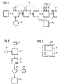
- FIG. 1 is shown in the form of a schematic representation in the form of a block diagram, the inventive device.
- the manufacturing process of a workpiece to be manufactured begins with the modeling of the workpiece on a CAD system 1 (Computer Aided Design).
- the geometry data of the workpiece determined with the aid of the CAD system 1 are forwarded as an input quantity to a CAM system 3 (Computer Aided Manufacturing), which is represented by an arrow 2.
- CAD system 1 Computer Aided Design
- CAM system 3 Computer Aided Manufacturing
- the milling paths are determined from the geometry data of the workpiece to be manufactured and the subsequent configuration of the machine tool, as well as the geometric data of a blank which later forms the output part for the machining operation on the machine tool are to be moved from the machine axes of the machine tool for producing the workpiece from the blank.
- the movements of the machine axes necessary for the production of the workpiece are determined by the CAM system 3 and provided as input to a so-called post-processor 5, which is indicated by an arrow 4 in FIG FIG. 1 is shown.
- the post-processor 5 which is in the form of a program running on a computer, generates a part program from the movements of the machine axes determined by the CAM system and the later configuration of the machine tool, in particular an NC part program with the aid of which Control device of the machine tool, the machining operation of the machine tool controls to produce the workpiece from the blank.
- the part program is usually in the form of a file that contains ASCII code line by line, usually written in DIN code commands.
- a command eg G3 X115 Y113.3 I-93 J25.52
- Such a command may be, for example, to move a tool (eg a milling cutter) along a circular path section to a target position in order to mill a recess out of the blank, for example.
- the individual commands of the part program are read in later by the control device 9 of the machine tool.
- the control device 9 calculates position setpoint values Xsetpoint n for each drive n of the drive system 10 of the machine tool in accordance with the commands of the part program.
- the parts program to a simulation unit 7, which may be formed, for example in the form of a simulation program that runs on a computer, forwarded, which is represented by an arrow 6 .
- the simulation unit 7 which includes a more or less detailed replica of the machine tool
- the later real machining operation is simulated and thus the part program generated by the post-processor 5 checks whether, for example during the machining process collision of machine elements with each other or with the blank occur and / or whether the intended processing times and machining accuracies are adhered to. If the simulation is successful, ie the machining process proceeds without errors with the desired result, the part program tested in this way is transmitted to the control device 9, which is indicated by an arrow 8 in FIG FIG. 1 is shown and the real machining process of the machine tool can start.
- simulation configuration the configuration of the machine tool used in the simulation by the simulation unit 7, hereinafter referred to as simulation configuration, does not coincide with the actual configuration of the actual machine tool actually present later.
- the simulation may be performed with a machine tool simulation configuration assuming that a 8mm diameter drill is present at a particular location of the tool magazine of the tool changer, but actually later on the actual machine tool, at the particular one Place, a drill with a cross section 10 is present.
- the simulation unit 7 is generated in the part program that was generated by the post-processor 5, the simulation configuration, ie the configuration of the machine tool with which the simulation was performed, stored in the part program.
- the simulation unit 7 creates a part program in which the machining process using a simulation configuration of a machine tool and a part program is not yet stored in the simulation configuration, is simulated, and then the simulation configuration is stored in the part program.
- the part program 24 thus created is in FIG. 3 shown.
- the parts program 24 thus consists of the instructions 25 of the parts program from the post-processor 5 and the simulation configuration 18.
- the parts program 24 is usually in the form of a file containing the instructions 25 and the simulation configuration 18.
- the deposit of the simulation configuration 18 in the part program is done, for example, by storing the simulation configuration 18 in the file.
- the control device 9 of the machine tool determines the current configuration of the machine tool before it starts the machining process of the machine tool, for example on the basis of an image acquisition device 11, a sensor 12 and / or a built-in machine tool
- the image acquisition device 11 which may be in the form of a camera
- the current position of tool clamping elements (tool clamping element data) and the position of the blank (raw part data) can be detected.
- the assembly can be detected with tools of the tool change.
- the measuring device 13 can for example measure the dimension of the blank.
- the current configuration is compared with the stored in the part program simulation configuration 18 of the machine tool, in case of non-compliance of current configuration with the simulation configuration generates a warning message W and transmitted eg to a control unit 14 and on Operating unit 14 visualized the operator is. Only if the current configuration and simulation configuration match, the processing operation is started by the control device 9.
- the simulation configuration is stored encrypted in the parts program 24 by the simulation unit 7, and the control unit 9 decrypts the simulation configuration 18 stored in the parts program before it compares the current configuration with the simulation configuration. As a result, subsequent manipulations of the simulation configuration stored in the parts program can be reliably prevented.
- the automatically determined current configuration is transmitted to the CAM system 3 and / or the post-processor 5 and / or to the simulation unit 7, which is represented by arrows 16.
- Manual determination and / or adaptation of the configuration of the machine tool used in the CAM system, in the post-processor and in the simulation can thus be dispensed with.
- the device for operating a machine tool can in the simplest case only in the form of a control device 9 for controlling the machine tool without the simulation unit 7, be formed.
- the device for operating a machine tool can also be described as a system consisting of the control device 9 and one of them structurally separate, e.g. be in an office set up computer, on which the simulation unit 7 runs in the form of a simulation program to be formed. Furthermore, it is also possible in this connection that the device for operating the machine tool is in the form of the control device 9 and the simulation unit 7, e.g. in the form of a program running on the control device 9 and thus is an integral part of the control device 9.
- the control device 9 may e.g. be designed as numerical control (NC control).
- FIG. 2 is the method according to the invention in the form of a flowchart again shown schematically.
- the part program 19, which at this time also does not contain a simulation configuration, is tested taking into account the simulation configuration 18 as part of a simulation 17 and a part program 24 in which the simulation configuration 18 is stored is generated.
- the determination 20 of the current configuration 26 of the machine tool takes place, wherein subsequently a comparison 21 of the current configuration 26 with the simulation configuration is carried out. If the current configuration does not match the simulation configuration, generation 22 of a warning occurs. If the current configuration agrees with the simulation configuration, the start 23 of the machining process takes place.
Claims (15)
- Procédé pour faire fonctionner une machine-outil, dans lequel une opération d'usinage de la machine-outil peut être commandé au moyen d'un sous-programme ( 24 ), caractérisé en ce que l'on détermine une configuration ( 26 ) présente de la machine-outil, en ce que l'on compare la configuration ( 26 ) présente à une configuration ( 18 ) de simulation de la machine-outil mémorisée dans le sous-programme ( 24 ) et en ce que, si la configuration présente ne coïncide pas avec la configuration ( 18 ) de simulation, on produit un message ( W ) d'avertissement.
- Procédé suivant la revendication 1, caractérisé en ce que, si la configuration ( 26 ) présente et la configuration ( 18 ) de simulation coïncident, on lance la configuration d'usinage et, si la configuration ( 26 ) présente ne coïncide pas avec la configuration ( 18 ) de simulation, on ne lance pas l'opération d'usinage.
- Procédé suivant l'une des revendications précédentes, caractérisé en ce que l'on mémorise la configuration ( 18 ) de simulation de manière chiffrée dans le sous-programme ( 24 ) et on la déchiffre.
- Procédé suivant l'une des revendications précédentes, caractérisé en ce que l'on détermine au moins des parties de la configuration ( 26 ) présente à l'aide d'un dispositif ( 11 ) d'acquisition d'image et/ou d'un capteur de ( 12 ) et/ou d'un dispositif ( 13 ) de mesure.
- Procédé suivant l'une des revendications précédentes, caractérisé en ce que la configuration ( 26 ) présente se présente sous la forme de données d'outillage d'outil et/ou de sous-données brutes et/ou de données d'éléments de serrage d'outil et/ou de la configuration logicielle.
- Procédé suivant l'une des revendications précédentes, caractérisé en ce que l'on élabore le sous-programme ( 24 ) en simulant l'opération d'usinage, en utilisant une configuration de simulation de la machine-outil et un sous-programme ( 19 ) dans lequel la configuration ( 18 ) de simulation n'est pas encore mémorisée et ensuite en mémorisant la configuration ( 18 ) de simulation dans le sous-programme ( 19 ) dans lequel la configuration ( 18 ) de simulation n'est pas encore mémorisée.
- Procédé suivant la revendication 6, caractérisé en ce que l'on mémorise la configuration ( 18 ) de simulation de manière chiffrée.
- Dispositif ( 9 ) pour faire fonctionner une machine-outil, le dispositif ( 15 ) commandant l'opération d'usinage de la machine-outil au moyen d'un sous-programme ( 29 ), caractérisé en ce que le dispositif ( 9 ) est constitué de manière à ce qu'une configuration ( 26 ) présente de la machine-outil puisse être déterminée par le dispositif ( 9 ) et de manière à ce que la configuration ( 26 ) présente puisse être comparée par le dispositif ( 9 ) à une configuration ( 18 ) de simulation de la machine-outil mémorisée dans le sous-programme ( 24 ) et, si la configuration ( 26 ) présente ne coïncide pas avec la configuration (18) de simulation, à pouvoir produire un message ( W ) d'avertissement par le dispositif ( 9 ).
- Dispositif suivant la revendication 8, caractérisé en ce que, si la configuration ( 26 ) présente et la configuration ( 18 ) de simulation coïncident, l'opération d'usinage est lancée par le dispositif ( 9 ) et, si la configuration ( 26 ) présente et la configuration ( 18 ) de simulation ne coïncident pas, l'opération d'usinage n'est pas lancée par le dispositif ( 9 ).
- Dispositif suivant la revendication 8 ou 9, caractérisé en ce que la configuration ( 18 ) de simulation est mémorisée de manière chiffrée dans le sous-programme ( 24 ) et peut être déchiffrée par le dispositif ( 9 ).
- Dispositif suivant l'une des revendications 8 à 10, caractérisé en ce qu'au moins des parties de la configuration présente peuvent être déterminées par le dispositif ( 9 ) à l'aide d'un dispositif ( 11 ) d'acquisition d'image et/ou d'un capteur ( 12 ) et/ou d'un dispositif ( 13 ) de mesure.
- Dispositif suivant l'une des revendications 8 à 11, caractérisé en ce que la configuration ( 26 ) présente se présente sous la forme de données d'outillage d'outil et/ou de sous-données brutes et/ou de données d'élément de serrage d'outil et/ou de la configuration logicielle.
- Dispositif suivant l'une des revendications 8 à 12, caractérisé en ce que le dispositif est constitué de manière à ce que le sous-programme ( 24 ) soit élaboré par le dispositif ( 7, 9 ) par le fait que l'opération d'usinage est simulée en utilisant une configuration ( 18 ) de simulation de la machine-outil et un sous-programme ( 19 ) dans lequel la configuration ( 18 ) de simulation n'est pas encore mémorisée et ensuite par le fait que la configuration ( 18 ) de simulation est mémorisée dans le sous-programme ( 19 ) dans lequel la configuration ( 18 ) de simulation n'est pas encore mémorisée.
- Dispositif suivant la revendication 13, caractérisé en ce que la configuration ( 18 ) de mémorisation est mémorisée dans le sous-programme ( 24 ) de manière chiffrée.
- Machine-outil comprenant un dispositif selon les revendications 8 à 14.
Priority Applications (3)
| Application Number | Priority Date | Filing Date | Title |
|---|---|---|---|
| EP07021943A EP2058717B1 (fr) | 2007-11-12 | 2007-11-12 | Procédé et dispositif destinés au fonctionnement d'une machine-outil |
| JP2008287534A JP5522926B2 (ja) | 2007-11-12 | 2008-11-10 | 工作機械の運転方法および装置 |
| US12/267,987 US8326448B2 (en) | 2007-11-12 | 2008-11-10 | Method and device for operating a machine tool |
Applications Claiming Priority (1)
| Application Number | Priority Date | Filing Date | Title |
|---|---|---|---|
| EP07021943A EP2058717B1 (fr) | 2007-11-12 | 2007-11-12 | Procédé et dispositif destinés au fonctionnement d'une machine-outil |
Publications (2)
| Publication Number | Publication Date |
|---|---|
| EP2058717A1 EP2058717A1 (fr) | 2009-05-13 |
| EP2058717B1 true EP2058717B1 (fr) | 2011-07-20 |
Family
ID=39113679
Family Applications (1)
| Application Number | Title | Priority Date | Filing Date |
|---|---|---|---|
| EP07021943A Active EP2058717B1 (fr) | 2007-11-12 | 2007-11-12 | Procédé et dispositif destinés au fonctionnement d'une machine-outil |
Country Status (3)
| Country | Link |
|---|---|
| US (1) | US8326448B2 (fr) |
| EP (1) | EP2058717B1 (fr) |
| JP (1) | JP5522926B2 (fr) |
Families Citing this family (18)
| Publication number | Priority date | Publication date | Assignee | Title |
|---|---|---|---|---|
| DE102004061579A1 (de) * | 2004-12-21 | 2006-07-06 | Siemens Ag | Modul zur Nachbildung eines Gebersignals |
| DE102009037237A1 (de) * | 2009-08-12 | 2011-02-17 | Repower Systems Ag | Verfahren und Anordnung zur automatischen Konfigurationsparameterkontrolle bei Windenergieanlagen |
| WO2011135611A1 (fr) * | 2010-04-27 | 2011-11-03 | 三菱電機株式会社 | Dispositif de commande numérique |
| JP2012053508A (ja) * | 2010-08-31 | 2012-03-15 | Mitsubishi Heavy Ind Ltd | 数値制御工作機械 |
| CN104245228B (zh) * | 2012-04-17 | 2018-04-20 | 株式会社牧野铣床制作所 | 机床的干涉判定方法和干涉判定装置 |
| JP6066041B2 (ja) * | 2012-07-17 | 2017-01-25 | 三菱日立パワーシステムズ株式会社 | 加工支援装置および加工支援システム |
| EP3045993A1 (fr) * | 2015-01-15 | 2016-07-20 | Siemens Aktiengesellschaft | Système de fabrication ayant une fonctionnalité supplémentaire et procédé de fonctionnement |
| JP2016218550A (ja) * | 2015-05-15 | 2016-12-22 | ファナック株式会社 | 加工に使用する工具の取付け状態を確認する数値制御装置 |
| EP3415781B1 (fr) | 2015-06-04 | 2020-04-22 | Meritor Heavy Vehicle Braking Systems (UK) Limited | Ensemble de guide |
| DE102015213614A1 (de) * | 2015-07-20 | 2017-01-26 | Siemens Aktiengesellschaft | Verfahren zum Bearbeiten von Werkstücken |
| US10635073B2 (en) | 2016-01-14 | 2020-04-28 | 2141632 Ontario Inc. | Electronically controlled substrate working apparatus |
| US10401823B2 (en) | 2016-02-04 | 2019-09-03 | Makino Inc. | Real time machining process monitoring utilizing preprocess simulation |
| CN112955834A (zh) * | 2019-09-27 | 2021-06-11 | 法国圣戈班玻璃厂 | 用于利用集成的数字映像弯曲玻璃板的自动化的生产工艺和生产系统 |
| WO2021058529A1 (fr) * | 2019-09-27 | 2021-04-01 | Saint-Gobain Glass France | Procédé de fabrication automatisé et système de fabrication pour plier des vitres à l'aide d'une image numérique intégrée |
| CN112955836A (zh) * | 2019-09-27 | 2021-06-11 | 法国圣戈班玻璃厂 | 用于利用集成的数字映像弯曲玻璃板的自动化的生产工艺和生产系统 |
| JP7464712B2 (ja) | 2020-07-03 | 2024-04-09 | ファナック株式会社 | ポストプロセッサ、加工プログラム生成方法、cnc加工システム及び加工プログラム生成用プログラム |
| EP4105745A1 (fr) | 2021-06-14 | 2022-12-21 | Siemens Aktiengesellschaft | Génération et traitement des instructions de programme chiffrées à l'aide d'un dispositif à commande numérique |
| EP4160457A1 (fr) | 2021-09-30 | 2023-04-05 | Siemens Aktiengesellschaft | Chiffrement des instructions du programme sur un dispositif de commande numérique |
Family Cites Families (59)
| Publication number | Priority date | Publication date | Assignee | Title |
|---|---|---|---|---|
| US4309600A (en) * | 1967-12-15 | 1982-01-05 | Cincinnati Milacron Inc. | Machine tool |
| US4531182A (en) * | 1969-11-24 | 1985-07-23 | Hyatt Gilbert P | Machine control system operating from remote commands |
| US3686639A (en) * | 1969-12-11 | 1972-08-22 | Modicon Corp | Digital computer-industrial controller system and apparatus |
| US3895354A (en) * | 1973-08-31 | 1975-07-15 | Warner Swasey Co | Program editor for machine control |
| JPS59216208A (ja) * | 1983-05-23 | 1984-12-06 | Mitsubishi Electric Corp | 数値制御装置 |
| DE3427127A1 (de) * | 1984-07-23 | 1986-01-23 | Siemens AG, 1000 Berlin und 8000 München | Verfahren zur regleroptimierung fuer antriebe |
| US4636938A (en) * | 1984-08-31 | 1987-01-13 | Cincinnati Milacron Inc. | Method and apparatus for producing numerical control programs |
| JPS6195407A (ja) * | 1984-10-16 | 1986-05-14 | Mitsubishi Electric Corp | 数値制御工作機械の状態報告方法 |
| JPS62199338A (ja) * | 1986-02-27 | 1987-09-03 | Fanuc Ltd | 工具衝突自動防止方法 |
| JP2612225B2 (ja) * | 1993-07-23 | 1997-05-21 | 株式会社東芝 | Nc工作機械 |
| US5691909A (en) * | 1995-12-29 | 1997-11-25 | Western Atlas | Method of virtual machining to predict the accuracy of part to be made with machine tools |
| US5822207A (en) * | 1996-05-06 | 1998-10-13 | Amadasoft America, Inc. | Apparatus and method for integrating intelligent manufacturing system with expert sheet metal planning and bending system |
| US5864482A (en) * | 1996-05-06 | 1999-01-26 | Amadasoft America, Inc. | Apparatus and method for managing distributing design and manufacturing information throughout a sheet metal production facility |
| US5971589A (en) * | 1996-05-06 | 1999-10-26 | Amadasoft America, Inc. | Apparatus and method for managing and distributing design and manufacturing information throughout a sheet metal production facility |
| US5886897A (en) * | 1996-05-06 | 1999-03-23 | Amada Soft America Inc. | Apparatus and method for managing and distributing design and manufacturing information throughout a sheet metal production facility |
| US5920483A (en) * | 1996-06-06 | 1999-07-06 | The Boeing Company | Scaling machine media for thermal effects to improve machine accuracy |
| AUPO206596A0 (en) * | 1996-08-30 | 1996-09-26 | Anca Pty Ltd | Tool grinding simulation system |
| JPH10214111A (ja) * | 1996-11-28 | 1998-08-11 | Fujitsu Ltd | デ−タ照合方法ならびにそのためのデ−タ照合装置および記憶媒体 |
| US6349237B1 (en) * | 1997-12-23 | 2002-02-19 | The Regents Of The University Of Michigan | Reconfigurable manufacturing system having a production capacity method for designing same and method for changing its production capacity |
| US6477683B1 (en) * | 1999-02-05 | 2002-11-05 | Tensilica, Inc. | Automated processor generation system for designing a configurable processor and method for the same |
| US20030023435A1 (en) * | 2000-07-13 | 2003-01-30 | Josephson Daryl Craig | Interfacing apparatus and methods |
| JP4329248B2 (ja) * | 2000-09-05 | 2009-09-09 | 株式会社森精機製作所 | Nc加工シミュレーション装置 |
| EP1238740B1 (fr) * | 2001-03-05 | 2008-05-14 | Charmilles Technologies S.A. | Procédé et dispositif pour usiner une pièce à trois dimensions par fraisage électroérosif |
| US6608282B2 (en) * | 2001-04-12 | 2003-08-19 | W.A. Whitney Co. | Machine tool loading apparatus |
| DE10152765B4 (de) * | 2001-07-13 | 2015-11-12 | Siemens Aktiengesellschaft | Verfahren zur elektronischen Bereitstellung von Diensten für Maschinen über eine Datenkommunikationsverbindung |
| US20030045947A1 (en) * | 2001-08-30 | 2003-03-06 | The Boeing Company | System, method and computer program product for controlling the operation of motion devices by directly implementing electronic simulation information |
| DE10144932B4 (de) * | 2001-09-12 | 2014-07-31 | Siemens Aktiengesellschaft | Visualisierung von Werkstücken bei der Simulation von Fräsprozessen |
| US7552203B2 (en) * | 2001-10-17 | 2009-06-23 | The Boeing Company | Manufacturing method and software product for optimizing information flow |
| DE10297651T5 (de) * | 2002-02-07 | 2005-05-19 | Mitsubishi Denki K.K. | Numerisches Steuerverfahren und numerisches Steuersystem |
| KR100478732B1 (ko) * | 2002-03-20 | 2005-03-24 | 학교법인 포항공과대학교 | 지능형 스텝-수치 제어기 |
| US20040102872A1 (en) * | 2002-11-26 | 2004-05-27 | Schick Louis Andrew | Method and tool for power plant operational optimization |
| DE10307261A1 (de) * | 2003-02-20 | 2004-09-09 | Siemens Ag | Programmierplattform zur Erstellung von Teileprogrammen bei Werkzeug- oder Produktionsmaschinen |
| JP3853752B2 (ja) * | 2003-04-22 | 2006-12-06 | 三菱電機株式会社 | シミュレーション装置 |
| DE10345626A1 (de) * | 2003-09-29 | 2005-05-12 | Heidenhain Gmbh Dr Johannes | Numerische Steuerung mit Werkzeugmaschinensimulator |
| US8417370B2 (en) * | 2003-10-17 | 2013-04-09 | Hexagon Metrology Ab | Apparatus and method for dimensional metrology |
| DE10351781B4 (de) * | 2003-11-06 | 2006-12-07 | Siemens Ag | Rechnergestütztes Anpassungsverfahren für ein Anwenderprogramm für eine Werkzeugmaschine und hiermit korrespondierende Gegenstände |
| DE20321699U1 (de) * | 2003-11-12 | 2009-01-15 | Siemens Aktiengesellschaft | Rechner zum Durchführen eines Simulationsverfahrens für eine Bearbeitung eines Werkstücks durch eine Werkzeugmaschine |
| DE102004013615A1 (de) * | 2004-03-19 | 2005-10-13 | Siemens Ag | Betriebsverfahren für eine von einer Steuereinrichtung gesteuerte Werkzeugmaschine |
| US7729789B2 (en) * | 2004-05-04 | 2010-06-01 | Fisher-Rosemount Systems, Inc. | Process plant monitoring based on multivariate statistical analysis and on-line process simulation |
| DE602004020497D1 (de) * | 2004-08-12 | 2009-05-20 | Makino Milling Machine | Verfahren zur maschinellen bearbeitung eines werkstücks |
| US20060058907A1 (en) * | 2004-09-14 | 2006-03-16 | Ugs Corp. | System, method, and computer program product for machine tool programming |
| DE102004045933A1 (de) * | 2004-09-22 | 2006-03-30 | Siemens Ag | Verfahren zum Betrieb einer Automatisierungseinrichtung bzw. Vorrichtung zur Durchführung des Verfahrens |
| US20060129270A1 (en) * | 2004-12-10 | 2006-06-15 | Gerold Pankl | Processes and systems for creation of machine control for specialty machines requiring manual input |
| DE102005025338B4 (de) * | 2005-05-31 | 2019-03-14 | Siemens Aktiengesellschaft | 08.Verfahren zur Bearbeitung eines Werkstückes |
| DE102005043022A1 (de) * | 2005-09-09 | 2007-03-22 | Siemens Ag | Verfahren und/oder Vorrichtung zur Steuerung und/oder Überwachung einer Bewegung bei industriellen Maschinen |
| DE102005047543A1 (de) * | 2005-09-30 | 2007-04-05 | Siemens Ag | Verfahren zur Simulation eines Steuerungs- und/oder Maschinenverhaltens einer Werkzeugmaschine oder einer Produktionsmaschine |
| US7376480B2 (en) * | 2005-11-09 | 2008-05-20 | The Boeing Company | Multihead composite material application machine programming method and apparatus for manufacturing composite structures |
| US7536235B2 (en) * | 2005-12-22 | 2009-05-19 | The Boeing Company | Multihead composite material application machine post-processor method and apparatus for manufacturing composite structures |
| US7769481B2 (en) * | 2005-12-23 | 2010-08-03 | The Boeing Company | Head assignment system and method |
| US7747421B2 (en) * | 2005-12-23 | 2010-06-29 | The Boeing Company | Head assignment modeling and simulation |
| KR100722504B1 (ko) * | 2006-01-18 | 2007-05-29 | 학교법인 포항공과대학교 | 비선형 공정 계획 생성 방법 및 이를 이용한 인터넷 기반step-nc 시스템 |
| EP1818763A1 (fr) * | 2006-02-08 | 2007-08-15 | Hurco Companies Inc. | Simulateur de contrôle d'un ordinateur portable |
| DE102006009263A1 (de) * | 2006-02-28 | 2007-09-06 | Siemens Ag | System und Verfahren zur Analyse des Laufzeitverhaltens eines Steuerungsprogramms für einen Fertigungsprozess |
| WO2008011845A1 (fr) * | 2006-07-28 | 2008-01-31 | Siemens Aktiengesellschaft | Compensation de la compliance dépendant de la position pour une machine-outil |
| US8725283B2 (en) * | 2006-08-04 | 2014-05-13 | Hurco Companies, Inc. | Generalized kinematics system |
| US8024068B2 (en) * | 2006-08-04 | 2011-09-20 | Hurco Companies, Inc. | Machine tool control system |
| DE102006043390B4 (de) * | 2006-09-15 | 2010-05-27 | Dmg Electronics Gmbh | Vorrichtung und Verfahren zur Simulation eines Ablaufs zur Bearbeitung eines Werkstücks an einer Werkzeugmaschine |
| US9588511B2 (en) * | 2007-08-03 | 2017-03-07 | Hurco Companies, Inc. | Virtual machine manager |
| JP5139230B2 (ja) * | 2008-10-06 | 2013-02-06 | オークマ株式会社 | 数値制御装置における衝突防止装置 |
-
2007
- 2007-11-12 EP EP07021943A patent/EP2058717B1/fr active Active
-
2008
- 2008-11-10 JP JP2008287534A patent/JP5522926B2/ja active Active
- 2008-11-10 US US12/267,987 patent/US8326448B2/en active Active
Also Published As
| Publication number | Publication date |
|---|---|
| US8326448B2 (en) | 2012-12-04 |
| US20090198366A1 (en) | 2009-08-06 |
| JP5522926B2 (ja) | 2014-06-18 |
| EP2058717A1 (fr) | 2009-05-13 |
| JP2009123209A (ja) | 2009-06-04 |
Similar Documents
| Publication | Publication Date | Title |
|---|---|---|
| EP2058717B1 (fr) | Procédé et dispositif destinés au fonctionnement d'une machine-outil | |
| EP1894068B1 (fr) | Procede permettant le controle de qualite pour une machine industrielle en fonction | |
| EP3335086B1 (fr) | Procede et dispositif de commande destines a la commande optimale d'une machine-outil | |
| DE112015004939B4 (de) | Verfahren zum Optimieren der Produktivität eines Bearbeitungsprozesses einer CNC-Maschine | |
| DE102005047466B3 (de) | Verfahren zur Optimierung des Bearbeitungsprozesses bei einer Maschine | |
| DE112008003963B4 (de) | System und Verfahren zur Off-line-Programmierung eines Industrieroboters | |
| DE102017004366B4 (de) | Numerische Steuervorrichtung | |
| EP2849014B1 (fr) | Procédé de commande d'une machine à tailler les engrenages et machine à tailler les engrenages | |
| DE102005047543A1 (de) | Verfahren zur Simulation eines Steuerungs- und/oder Maschinenverhaltens einer Werkzeugmaschine oder einer Produktionsmaschine | |
| DE102016216190A1 (de) | Verfahren und System zum rechnergestützten Optimieren eines numerisch gesteuerten Bearbeitungsprozesses eines Werkstücks | |
| DE10114811A1 (de) | System und Verfahren zur Erstellung von mehrachsigen Bearbeitungs-Vorgängen an Werkstücken | |
| EP2691824A1 (fr) | Procédé d'usinage de pièces à l'aide d'un dispositif d'usinage de pièce à commande numérique et dispositif d'usinage de pièce à commande numérique | |
| DE112008004205T5 (de) | Verfahren und Vorrichtung zur Simulation einer NC-Bearbeitungsmaschine | |
| WO2014173469A1 (fr) | Commande numérique pouvant modifier le programme pièce | |
| DE102019110434A1 (de) | Werkzeugwahlvorrichtung und Maschinenlernvorrichtung | |
| EP3685969A1 (fr) | Optimisation assistée par ordinateur d'un usinage à commande numérique d'une pièce à usiner | |
| EP1592527B1 (fr) | Procede et dispositif pour fraiser des surfaces de forme libre | |
| EP3045986A1 (fr) | Machine de fabrication avec contrôle de fonctionnalité propre et procédé | |
| DE10255033A1 (de) | Werkzeugmaschine und Verfahren zum Betreiben einer solchen | |
| EP2140321A1 (fr) | Commande de machines-outils comportant un magasin d'outils et un compartiment de stockage intermédiaire | |
| EP3242179A1 (fr) | Procede d'usinage d'une piece | |
| EP3224680B1 (fr) | Système de production à fonctionnalité supplémentaire et procédé de fonctionnement | |
| WO2008113305A1 (fr) | Dispositif permettant d'élaborer des programmes d'usinage pour une machine d'usinage | |
| CH702705B1 (de) | Verfahren zur Fertigung von einer Schaufel für Turbinen oder Verdichter. | |
| EP3712724A1 (fr) | Agencement d'automatisation, procédé de fonctionnement de l'agencement d'automatisation ainsi que programme informatique |
Legal Events
| Date | Code | Title | Description |
|---|---|---|---|
| PUAI | Public reference made under article 153(3) epc to a published international application that has entered the european phase |
Free format text: ORIGINAL CODE: 0009012 |
|
| AK | Designated contracting states |
Kind code of ref document: A1 Designated state(s): AT BE BG CH CY CZ DE DK EE ES FI FR GB GR HU IE IS IT LI LT LU LV MC MT NL PL PT RO SE SI SK TR |
|
| AX | Request for extension of the european patent |
Extension state: AL BA HR MK RS |
|
| 17P | Request for examination filed |
Effective date: 20090918 |
|
| AKX | Designation fees paid |
Designated state(s): DE |
|
| GRAP | Despatch of communication of intention to grant a patent |
Free format text: ORIGINAL CODE: EPIDOSNIGR1 |
|
| GRAS | Grant fee paid |
Free format text: ORIGINAL CODE: EPIDOSNIGR3 |
|
| GRAA | (expected) grant |
Free format text: ORIGINAL CODE: 0009210 |
|
| AK | Designated contracting states |
Kind code of ref document: B1 Designated state(s): DE |
|
| REG | Reference to a national code |
Ref country code: DE Ref legal event code: R096 Ref document number: 502007007696 Country of ref document: DE Effective date: 20110908 |
|
| PLBE | No opposition filed within time limit |
Free format text: ORIGINAL CODE: 0009261 |
|
| STAA | Information on the status of an ep patent application or granted ep patent |
Free format text: STATUS: NO OPPOSITION FILED WITHIN TIME LIMIT |
|
| 26N | No opposition filed |
Effective date: 20120423 |
|
| REG | Reference to a national code |
Ref country code: DE Ref legal event code: R097 Ref document number: 502007007696 Country of ref document: DE Effective date: 20120423 |
|
| PGFP | Annual fee paid to national office [announced via postgrant information from national office to epo] |
Ref country code: DE Payment date: 20230119 Year of fee payment: 16 |