EP2058711B1 - Cartouche de procédé avec appareil d'application de lubrifiant et appareil de formation d'images l'utilisant - Google Patents
Cartouche de procédé avec appareil d'application de lubrifiant et appareil de formation d'images l'utilisant Download PDFInfo
- Publication number
- EP2058711B1 EP2058711B1 EP08167503.5A EP08167503A EP2058711B1 EP 2058711 B1 EP2058711 B1 EP 2058711B1 EP 08167503 A EP08167503 A EP 08167503A EP 2058711 B1 EP2058711 B1 EP 2058711B1
- Authority
- EP
- European Patent Office
- Prior art keywords
- blade
- lubricant
- carrying member
- photoconductor
- contact
- Prior art date
- Legal status (The legal status is an assumption and is not a legal conclusion. Google has not performed a legal analysis and makes no representation as to the accuracy of the status listed.)
- Active
Links
- 239000000314 lubricant Substances 0.000 title claims description 176
- 238000000034 method Methods 0.000 title claims description 59
- 230000008569 process Effects 0.000 title claims description 48
- 238000004140 cleaning Methods 0.000 claims description 93
- 238000011161 development Methods 0.000 claims description 28
- 238000012546 transfer Methods 0.000 description 46
- 238000009499 grossing Methods 0.000 description 35
- 230000000052 comparative effect Effects 0.000 description 26
- 239000000463 material Substances 0.000 description 14
- 229920003225 polyurethane elastomer Polymers 0.000 description 13
- 238000012360 testing method Methods 0.000 description 12
- 239000002699 waste material Substances 0.000 description 12
- 238000011156 evaluation Methods 0.000 description 11
- 108091008695 photoreceptors Proteins 0.000 description 10
- 230000002159 abnormal effect Effects 0.000 description 9
- 238000011084 recovery Methods 0.000 description 8
- 206010039740 Screaming Diseases 0.000 description 7
- 239000003795 chemical substances by application Substances 0.000 description 7
- 230000007246 mechanism Effects 0.000 description 7
- 238000011109 contamination Methods 0.000 description 5
- 239000002245 particle Substances 0.000 description 5
- 238000011144 upstream manufacturing Methods 0.000 description 5
- 238000007600 charging Methods 0.000 description 4
- 239000004020 conductor Substances 0.000 description 4
- 238000012423 maintenance Methods 0.000 description 4
- 239000000843 powder Substances 0.000 description 4
- 230000015572 biosynthetic process Effects 0.000 description 3
- 230000000694 effects Effects 0.000 description 3
- 239000002184 metal Substances 0.000 description 3
- 229910052751 metal Inorganic materials 0.000 description 3
- 230000003287 optical effect Effects 0.000 description 3
- 239000011347 resin Substances 0.000 description 3
- 229920005989 resin Polymers 0.000 description 3
- XOOUIPVCVHRTMJ-UHFFFAOYSA-L zinc stearate Chemical compound [Zn+2].CCCCCCCCCCCCCCCCCC([O-])=O.CCCCCCCCCCCCCCCCCC([O-])=O XOOUIPVCVHRTMJ-UHFFFAOYSA-L 0.000 description 3
- VYPSYNLAJGMNEJ-UHFFFAOYSA-N Silicium dioxide Chemical compound O=[Si]=O VYPSYNLAJGMNEJ-UHFFFAOYSA-N 0.000 description 2
- 239000000654 additive Substances 0.000 description 2
- 239000000835 fiber Substances 0.000 description 2
- 229920006311 Urethane elastomer Polymers 0.000 description 1
- 239000002253 acid Substances 0.000 description 1
- 230000000996 additive effect Effects 0.000 description 1
- 238000013019 agitation Methods 0.000 description 1
- 125000001931 aliphatic group Chemical group 0.000 description 1
- PNEYBMLMFCGWSK-UHFFFAOYSA-N aluminium oxide Inorganic materials [O-2].[O-2].[O-2].[Al+3].[Al+3] PNEYBMLMFCGWSK-UHFFFAOYSA-N 0.000 description 1
- 239000003086 colorant Substances 0.000 description 1
- 238000004040 coloring Methods 0.000 description 1
- 230000001419 dependent effect Effects 0.000 description 1
- 230000006866 deterioration Effects 0.000 description 1
- 229920001971 elastomer Polymers 0.000 description 1
- 238000007786 electrostatic charging Methods 0.000 description 1
- 230000014509 gene expression Effects 0.000 description 1
- 230000001050 lubricating effect Effects 0.000 description 1
- 238000012986 modification Methods 0.000 description 1
- 230000004048 modification Effects 0.000 description 1
- 229920000642 polymer Polymers 0.000 description 1
- 239000011164 primary particle Substances 0.000 description 1
- 230000009467 reduction Effects 0.000 description 1
- 150000003839 salts Chemical class 0.000 description 1
- 238000007790 scraping Methods 0.000 description 1
- 239000000377 silicon dioxide Substances 0.000 description 1
- 239000007787 solid Substances 0.000 description 1
- 230000003068 static effect Effects 0.000 description 1
- 239000010409 thin film Substances 0.000 description 1
- 238000011179 visual inspection Methods 0.000 description 1
Images


Classifications
-
- G—PHYSICS
- G03—PHOTOGRAPHY; CINEMATOGRAPHY; ANALOGOUS TECHNIQUES USING WAVES OTHER THAN OPTICAL WAVES; ELECTROGRAPHY; HOLOGRAPHY
- G03G—ELECTROGRAPHY; ELECTROPHOTOGRAPHY; MAGNETOGRAPHY
- G03G21/00—Arrangements not provided for by groups G03G13/00 - G03G19/00, e.g. cleaning, elimination of residual charge
- G03G21/0094—Arrangements not provided for by groups G03G13/00 - G03G19/00, e.g. cleaning, elimination of residual charge fatigue treatment of the photoconductor
-
- G—PHYSICS
- G03—PHOTOGRAPHY; CINEMATOGRAPHY; ANALOGOUS TECHNIQUES USING WAVES OTHER THAN OPTICAL WAVES; ELECTROGRAPHY; HOLOGRAPHY
- G03G—ELECTROGRAPHY; ELECTROPHOTOGRAPHY; MAGNETOGRAPHY
- G03G2221/00—Processes not provided for by group G03G2215/00, e.g. cleaning or residual charge elimination
- G03G2221/16—Mechanical means for facilitating the maintenance of the apparatus, e.g. modular arrangements and complete machine concepts
- G03G2221/1606—Mechanical means for facilitating the maintenance of the apparatus, e.g. modular arrangements and complete machine concepts for the photosensitive element
- G03G2221/1609—Mechanical means for facilitating the maintenance of the apparatus, e.g. modular arrangements and complete machine concepts for the photosensitive element protective arrangements for preventing damage
Definitions
- the present disclosure generally relates to a lubricant application apparatus including a blade for smoothing lubricant supplied on a surface of an image carrying member, and an image forming apparatus, such as a copier, a facsimile, or a printer, and a process cartridge using such a lubricant application apparatus.
- an image forming apparatus using electrophotography includes a cleaning unit that cleans a surface of an image carrying member after transferring an image from the image carrying member to a transfer member (e.g. a sheet). For example, after an image transfer process, toner may remain on the surface of the image carrying member, and such remaining toner needs to be removed to prepare the image carrying member for another image forming process.
- a cleaning unit may typically use a cleaning blade made of an elastic member (e.g., polyurethane rubber) because such a blade may have a simple configuration and also a good level of a cleaning function for removing toner or the like.
- an image forming apparatus includes a lubricant supply unit, which supplies lubricant (e.g., aliphatic acid metal salt) to a surface of the image carrying member to reduce the friction coefficient between a cleaning blade and an image carrying member. If an amount of lubricant supplied to the surface of the image carrying member is not sufficient (e.g., lubricant amount is too little), such a friction coefficient may not be reduced sufficiently, and thereby some drawbacks may occur due to a high friction coefficient. For example, curling of the cleaning blade and a shorter lifetime of the image carrying member may result.
- lubricant e.g., aliphatic acid metal salt
- an amount of lubricant supplied to the surface of the image carrying member is excessive (e.g., lubricant amount is too great), some lubricant may adhere to devices or the like disposed around an image carrying member, and thereby some drawbacks may occur due to such lubricant adhesion. For example, an abnormal image may result due to lubricant adhesion to a charging device or a development agent carrier.
- a lubricant supply amount on to the image carrying member may need to be controlled to a given level.
- Japanese Patent Application Publication 2000-330443 (hereinafter background art 1) and Japanese Patent Application Publication 2001-305907 (hereinafter background art 2) disclose image forming apparatuses including a cleaning blade and a lubricant supply unit including a lubricant smoothing device.
- the lubricant supply unit is positioned at a downstream side of a surface movement direction of an image carrying member with respect to a contact point of the cleaning blade and the image carrying member, and thereby the lubricant smoothing device is positioned at a downstream side of a surface movement direction of an image carrying member with respect to the cleaning blade.
- the surface of the image carrying member is cleaned well before lubricant is supplied on to the image carrying member, and thereby lubricant supplied on to the surface of the image carrying member can be uniformly smoothed by the lubricant smoothing device. Further, such configurations can prevent a phenomenon that lubricant adheres to remaining toner, which remains on the image carrying member after a toner image transfer.
- Background arts 1 and 2 each disclose a lubricant smoothing device of blade type, but the lubricant smoothing devices are supported in different manners.
- the lubricant smoothing blade is supported by a counter-direction configuration. Specifically, a support device supports the lubricant smoothing blade from a downstream side of the surface movement direction of the image carrying member with respect to a contact area of the lubricant smoothing blade and a surface of an image carrying member.
- the lubricant smoothing blade is supported by a trailing-direction configuration. Specifically, a support device supports the lubricant smoothing blade from an upstream side of the surface movement direction of the image carrying member with respect to a contact area of the lubricant smoothing blade and a surface of an image carrying member.
- the lubricant smoothing blade can be contacted to the image carrying member with a higher contact pressure in the counter-direction configuration compared to the trailing-direction configuration. Accordingly, a phenomenon of lubricant passing through at a contact point of the lubricant smoothing blade can be prevented more effectively by employing the counter-direction configuration compared to the trailing-direction configuration.
- the lubricant smoothing device contacting the image carrying member moving in a given direction may vibrate due to a friction with the image carrying member even if the counter-direction configuration is employed.
- the lubricant smoothing blade may not stably contact the contact point with the image carrying member due to such a vibration. Under such a vibrated condition, the lubricant smoothing device may not function properly, and thereby some lubricant, which comes to the contact point of the lubricant smoothing blade, may not be screened by the lubricant smoothing blade. In other words, lubricant may pass through the lubricant smoothing device without an adequate control of a lubricant amount. If such a passing occurs, an amount of lubricant supplied to the image carrying member cannot be controlled properly, and thereby a resultantly produced image may have a lower image quality.
- JP 2005-321533 A relates to an image forming apparatus.
- Usable ranges of high temperature and high humidity (HH), medium temperature and medium humidity (MM) and low temperature and low humidity (LL) in the drawing show results obtained by evaluating the usable ranges of a cleaning blade under the three conditions from an escape amount of toner, and a region belonging to one of the ranges shows a range of contact conditions in which wear of the cleaning blade over time is evaluated and judged to be small under certain conditions of temperature and humidity.
- this range is represented by specific numerical values, a cleaning angle is 76-86°, a contact pressure is 0.14-0.36 N/cm and an amount of toner scraping through the cleaning blade is a concentration of 0.01-0.03.
- JP 2006-047698 A relates to an image forming method, image forming apparatus, and process cartridge for image forming apparatus.
- a cleaning unit includes an elastic blade containing inorganic particulate comprising alumina or silica, the content of the inorganic particulate in a thickness direction of the blade is larger than that in a photoreceptor non-contacting side, and a counter blade contacted in a rotation direction of a photoreceptor has an angle making the axially cut face and the surface of the photoreceptor in a photoreceptor contacting part, in a range of 80-100 degrees in an upstream direction of rotating the photoreceptor.
- JP 2006-064918 A relates to an image forming method and device, and process cartridge for image forming device.
- This is an image forming method at least applying electrostatic charging, image exposing, developing, and transferring, fixing, and cleaning to a photo conductor.
- the cleaning unit working as a cleaning means for cleaning has an elastic blade which is a counter blade in contact with the photo conductor in the reverse direction of the rotation.
- the cross section surface cut in the axial direction and the surface of the photo conductor make an angle of 90-110° toward the upstream of the rotation at the position the blade is in contact with the photo conductor.
- EP 1 521 138 A2 relates to an image forming method with tiny toner particles and apparatus with a blade for levelling a thin film of lubricant on a photosensitive surface.
- An image forming apparatus includes an image bearing member configured to bear a toner image on a surface thereof, a charging mechanism configured to charge the surface of the image bearing member uniformly, an intermediate transfer mechanism configured to transfer the toner image from the image bearing member onto an image receiver, a cleaning mechanism configured to clean the surface of the image bearing member after the toner image is transferred onto the image receiver; and a lubricant supplying mechanism configured to supply a lubricant contained therein onto the surface of the image bearing member and form a thin layer using a lubricating blade, the lubricant supplying mechanism being arranged at a position between the cleaning mechanism and the charging mechanism: whereby the surface of the image bearing member becomes more uniform for charging.
- toner images are formed by using essentially spherical toner particles having an average volume based diameter of at most 10
- JP 2003-058011 A relates to an image forming method and image forming device.
- a toner image is formed by using developer incorporating polymer toner on an electrophotographic photoreceptor and residual toner left after transferring the toner image to transfer material is removed by a cleaning device.
- the cleaning device has a conductive or semiconductive brush roll and a cleaning blade arranged on the more downstream side in the moving direction of the photoreceptor than the brush roll, and then the residual toner on the photoreceptor is removed by applying bias voltage having a reverse polarity to the toner to the brush roll and controlling the toner removing rate of the brush roll to be 30 to 70%.
- EP 1 744 227 A1 relates to an image forming apparatus with cleaning blade.
- An image forming apparatus in which a cleaning blade is brought into contact with a surface of the image bearing member to remove the toner remaining thereon, in which the static friction coefficient ⁇ of the image bearing member is from 0.1 to 0.3, the contact pressure of the cleaning blade to the image bearing member is from 1.5 to 10 g/cm, and the image bearing member and the cleaning blade satisfy the following relationships (1) and (2): 0.01 kg ⁇ T off ⁇ T 0 / r ⁇ 0 ⁇ .15 kg 1.2 ⁇ T on ⁇ T 0 / T off ⁇ T 0 ⁇ 3.8 , wherein T 0 represents the rotation torque (kgcm) of the image bearing member when the cleaning blade is not in contact with the surface of the image bearing member, T off represents the rotation torque (kgcm) of the image bearing member when the cleaning blade is brought into contact with the surface of the image bearing member, T on represents the rotation torque (kgcm) of the image bearing member when
- JP 2004-046073 A relates to an image forming method, image forming device, and process unit for the same.
- the image forming method has a cleaning stage of removing the toner remaining on the latent image carrier.
- a development stage a latent image on the latent image carrier is developed by using a toner where an external additive containing external additives A and B of which the primary particles have number-average particle diameters of ⁇ 20nm and ⁇ 15nm respectively is added to host particle essentially consisting of at least a binding resin and a coloring matter.
- a cleaning blade attached to a blade support member fixed on a casing supporting the latent image carrier, in a counter direction toward the surface of the latent image carrier is brought into contact with the latent image carrier with a contact pressure of 20 to 40g/cm to remove the toner remaining on the latent image carrier.
- a lubricant application apparatus includes a blade for smoothing lubricant supplied on to a surface of an image carrying member to control a lubricant amount supplied on to the surface of the image carrying member, and an image forming apparatus and a process cartridge using such a lubricant application apparatus.
- a lubricant application apparatus includes a lubricant application member and an elastic member.
- the lubricant application member applies lubricant to a lubricant receiving member moving in a given surface movement direction.
- the elastic member contacts the lubricant receiving member in a counter direction with respect to the surface movement direction of the lubricant receiving member, and smoothes the lubricant applied on to the lubricant receiving member.
- the elastic member is shaped as a blade.
- the elastic member is in contact with the lubricant receiving member at a contact area of the elastic member, in a counter direction, in which the elastic member is positioned at a downstream side of the surface movement direction of the lubricant receiving member with respect to the contact area of the elastic member.
- the elastic member is in contact with the lubricant receiving member at the contact area with a contact angle of 85 degrees or more.
- the contact angle is defined by an edge face of the elastic member and a tangent line at the contact point.
- a process cartridge detachably mountable to an image forming apparatus includes the above-described lubricant application apparatus, an image carrying member, and at least one of a development unit, a cleaning device, or a charge device.
- the process cartridge integrally supports the lubricant application apparatus, the image carrying member, and the at least one of the development unit, the cleaning device, or the charge device.
- an image forming apparatus includes an image carrying member, a charge device to charge the image carrying member, a cleaning device to clean materials adhered on the image carrying member, and the above-described lubricant application apparatus.
- first, second, etc. may be used herein to describe various elements, components, regions, layers and/or sections, it should be understood that such elements, components, regions, layers and/or sections are not limited thereby because such terms are relative, that is, used only to distinguish one element, component, region, layer or section from another region, layer or section.
- a first element, component, region, layer or section discussed below could be termed a second element, component, region, layer or section without departing from the teachings of the present invention.
- Such an image forming apparatus may be a color printer employing electrophotography, for example, but is not limited thereto.
- FIG. 1 illustrates a schematic cross-sectional view of an image forming apparatus 1 according to an example embodiment.
- the image forming apparatus 1 includes a housing 2, an image forming engine 3, an optical writing unit 4, a sheet cassette 5, a fixing unit 6, and a waste toner recovery unit 7, for example.
- the optical writing unit 4 emits a laser beam to write an image on an image carrying member.
- the sheet cassette 5 stores a given volume of recording medium P, which is used as a transfer medium for recording an image.
- the fixing unit 6 fixes a toner image transferred to the recording medium P.
- the waste toner recovery unit 7 recovers waste toner generated after a toner image transfer process.
- the image forming engine 3 forms a toner image and then transfers the toner image to the recording medium P.
- the image forming engine 3 includes photoconductors 8Y, 8C, 8M, 8K (which may each be identically formed, and may hereinafter be collectively referred to as "photoconductor 8"), a charge roller 9, a development unit 10, a first cleaning unit 11, primary transfer rollers 12, an intermediate transfer member 13, a secondary transfer roller 14, a second cleaning unit 15, for example.
- the charge roller 9, disposed around photoconductor 8 charges the photoconductor 8.
- the intermediate transfer member 13 carries an image (e.g., toner image) thereon transferred from the photoconductor 8.
- the secondary transfer roller 14 transfers the image (e.g., toner image) from the intermediate transfer member 13 to the recording medium P.
- the suffixes of Y, C, M, and K indicate respective colors of yellow, cyan, magenta, and black, and such suffixes may be omitted.
- the photoconductor 8 includes a photosensitive layer as its outer layer that is used for forming an electrostatic latent image.
- the photoconductor 8 may have a cylindrical form, and be connected to a drive motor, by which the photoconductor 8 can be rotated in a given direction about its axis.
- the charge roller 9 may be in contact with an outer surface of the photoconductor 8, or may be distanced from an outer surface of the photoconductor 8 by a small gap.
- the charge roller 9 is applied with voltage from a power source, by which a corona discharge occurs between the charge roller 9 and the photoconductor 8, and thereby the outer surface of the photoconductor 8 is uniformly charged.
- the optical writing unit 4 emits a light beam corresponding to image data to expose the outer surface of the photoconductor 8, uniformly charged as above, to form an electrostatic latent image corresponding to the image data on the outer surface of the photoconductor 8.
- the development unit 10 supplies toner to the photoconductor 8 to develop the electrostatic latent image on the outer surface of the photoconductor 8 as a toner image, in which toner is attracted on the electrostatic latent image formed on the outer surface of the photoconductor 8.
- the intermediate transfer member 13 may be a loop belt, made from a resin or a rubber used as a base material.
- the intermediate transfer member 13 is extended by a drive roller 16 connected to a drive motor, a guide roller 17, and a tension roller 18, for example.
- the drive roller 16 is rotated by the drive motor, the intermediate transfer member 13 travels in a direction shown by an arrow A in FIG. 1 .
- the guide roller 17 and the tension roller 18 are rotated using a friction force of the intermediate transfer member 13 traveling in the direction shown by an arrow A.
- the primary transfer rollers 12 are disposed at an inner surface side of the intermediate transfer member 13, and a transfer voltage is applied to the primary transfer roller 12 to transfer toner images on the photoconductor(s) 8 to the intermediate transfer member 13. Toner images formed on the photoconductor(s) 8 are sequentially transferred and superimposed on intermediate transfer member 13 to form a color toner image on the intermediate transfer member 13.
- the first cleaning unit 11 cleans the outer surface of the photoconductor 8 after the toner image is transferred to the intermediate transfer member 13. With such a cleaning process, remaining toner, paper powder, or the like remaining on the outer surface of the photoconductor 8 can be recovered after a toner image is transferred to the intermediate transfer member 13. Such recovered materials are referred to as waste toner hereinafter for simplicity of expressions.
- a color toner image formed on the intermediate transfer member 13 is transferred to the recording medium P at a transfer nip set between the intermediate transfer member 13 and the secondary transfer roller 14. Specifically, when the recording medium P is fed to the transfer nip, a transfer voltage is applied to the secondary transfer roller 14 to transfer the color toner from the intermediate transfer member 13 to the recording medium P.
- the recording medium P is transported from the sheet cassette 5 by a transport roller pair 19 and a registration roller pair 20 to the transfer nip. After transferring a toner image, the recording medium P is transported to the fixing unit 6.
- the fixing unit 6 applies heat and pressure to the recording medium P to melt and fix the toner image on the recording medium P. After the fixing process, the recording medium P is ejected to a sheet ejection tray 21 positioned on an outer side of the housing 2.
- the second cleaning unit 15 cleans an outer surface of the intermediate transfer member 13 after transferring a color toner image to the recording medium P. With such a cleaning process, toner, paper powder, or the like remaining on the intermediate transfer member 13 after a toner image transfer can be recovered. Such toner, paper powder, or the like is referred to as waste toner.
- waste toner recovered by the first cleaning unit 11 or the second cleaning unit 15 is transported to and stored in the waste toner recovery unit 7, which may be detachably mountable to the housing 2.
- the waste toner recovery unit 7 becomes full the waste toner recovery unit 7 is removed from the housing 2, and a new one is attached.
- the photoconductor 8 may be integrated with other devices or the like as a process cartridge 23, such as process cartridges 23Y, 23C, 23M, and 23K as shown in FIG. 1 .
- the photoconductor 8 and at least one of the charge roller 9, the development unit 10, or the first cleaning unit 11 may be integrally encased in a case 22 so as to configure the process cartridge 23.
- the process cartridge 23 can include the photoconductor 8 and at least one of the charge roller 9, the development unit 10, or the first cleaning unit 11.
- Such a configuration of the process cartridge 23 is not limited thereto, but may include a variety of devices or the like.
- the process cartridge 23 may be detachably mountable to the housing 2. If the photoconductor 8, the charge roller 9, the development unit 10, and the first cleaning unit 11 are integrated as the process cartridge 23, for example, a replacement work or maintenance work of each of the devices or the like can be conducted easily by removing the process cartridge 23 from the image forming apparatus 1. Further, the photoconductor 8, the charge roller 9, the development unit 10, and the first cleaning unit 11 need to be positioned relative to one another in a precise manner. By integrating such devices or the like, such relative positioning of such devices or the like can be maintained in a higher precision, and thereby higher image quality can be maintained.
- a configuration of the process cartridge 23 is not limited thereto, but may include a variety of devices or the like.
- the photoconductor 8, the charge roller 9, the development unit 10, and the first cleaning unit 11 may be integrated as one unit.
- the process cartridge 23 may be configured in various manners.
- the process cartridge 23 may include the photoconductor 8 and at least one of the charge roller 9, the development unit 10, or the first cleaning unit 11 as one unit using a casing or the like.
- FIG. 2 illustrates a perspective view of the image forming apparatus 1, in which an outer cover 24 is opened from the housing 2.
- the image forming engine 3, the waste toner recovery unit 7, or the like are exposed, and a replacement work or a maintenance work for the process cartridge 23, the intermediate transfer member 13, the waste toner recovery unit 7, or the like can be conducted.
- the intermediate transfer member 13, the rollers 16, 17, 18, and the second cleaning unit 15 may be encased in a belt case 13a as one integrated unit.
- FIG. 3 illustrates an expanded view of the photoconductor 8 and its surroundings in an exemplary embodiment, in which details of the development unit 10 are omitted.
- the photoconductor can be rotated in a direction shown by an arrow B in FIG. 3 , for example.
- a charge unit 90 includes the charge roller 9 made of chargeable material, and a pressure spring 36, for example.
- the pressure spring 36 applies a given pressure to the charge roller 9 to press the charge roller 9 toward the photoconductor 8.
- the charge roller 9 includes a conductive shaft and a conductive elastic layer formed on the conductive shaft. When a voltage is supplied to the conductive shaft from a power source, a given potential is generated in a gap between the conductive elastic layer of the charge roller 9 and the photoconductor 8, by which the photoconductor 8 is charged to a given potential having a given polarity. Further, the charge unit 90 includes a cleaning roller 37 to remove residuals on the charge roller 9.
- the development unit 10 may use two-component development agent, or one-component development agent.
- development agent stirred well by an agitation screw is magnetically carried on a development roller (used as a development agent carrier), and a doctor blade is used to form a thin layer of development agent on the development roller.
- the development agent With a rotation of the development roller, the development agent is transported to a development-process area facing the photoconductor 8, and an electrostatic latent image on the photoconductor 8 is developed as a toner image at the development-process area.
- the first cleaning unit 11 includes a cleaning blade 31 as a cleaning device and a blade holder 30 supporting the cleaning blade 31.
- the blade holder 30 supports the cleaning blade 31 at a position at a downstream side of a surface movement direction of the photoconductor 8 so as to support and contact the cleaning blade 31 against the surface of the photoconductor 8 in a counter-direction configuration.
- the cleaning blade 31 contacts the surface of the photoconductor 8 with a contact angle of 79 degrees at its contact area 31a and a contact pressure of 20 N/m.
- the cleaning blade 31 is made of urethane rubber having a JIS-A hardness of 72 degree, a thickness of 1.8 mm, a width of 326 mm, a length of 11.5 mm, a free end length of 7.6 mm, and the cleaning blade 31 contacts the surface of the photoconductor 8 with a contact angle of 90 degrees at its contact area 31a, for example (JIS is Japan Industrial Standard).
- the first cleaning unit 11 may further include a toner recovery coil 32 to transport toner recovered by the cleaning blade 31 to a waste toner bottle.
- the lubricant application unit 47 is positioned between the first cleaning unit 11 and the charge unit 90. Specifically, the lubricant application unit 47 is at a downstream side of surface movement direction of the photoconductor 8 with respect to the first cleaning unit 11, and the lubricant application unit 47 is at an upstream side of a surface movement direction of the photoconductor 8 with respect to the charge unit 90.
- the lubricant application unit 47 includes a brush roller 33, a lubricant block 34, and a bias spring 35, for example.
- the brush roller 33 is used to supply lubricant to the photoconductor 8.
- the lubricant block 34 e.g., zinc stearate block
- the bias spring 35 presses the lubricant block 34 against the brush roller 33.
- the brush roller 33 contacting the photoconductor 8, rotates in a counter direction with respect to the photoconductor 8 as shown in FIG. 3 , for example.
- the brush roller 33 may include a metal shaft and brush fibers implanted on the metal shaft.
- the brush fibers scrape lubricant from the lubricant block 34, and apply the scraped lubricant powder on to the photoconductor 8.
- zinc stearate is used as lubricant in the example, other lubricants can be used.
- the lubricant application unit 47 further includes a blade 39 and a blade holder 40.
- the blade 39 contacts the photoconductor 8 with a given contact pressure (e.g., 20 N/m) at a downstream side of the surface movement direction of the photoconductor 8 with respect to the brush roller 33, contactable to the photoconductor 8.
- the blade 39 is made of a resin material such as for example polyurethane rubber.
- the blade holder 40 supports the blade 39 at a position at a downstream side of the surface movement direction of the photoconductor 8 so as to support and contact the blade 39 against the surface of the photoconductor 8 in a counter-direction configuration.
- the blade 39 contacts the surface of the photoconductor 8 at its contact area 39a with a contact angle of 79 degrees and a contact pressure of 20 N/m.
- the blade 39 has a thickness of 1.5 mm, a width of 326 mm, a length of 10.0 mm, a free end length of 6.0 mm, and the blade 39 contacts the surface of the photoconductor 8 with a contact angle of 90 degrees at its contact area 39a, for example.
- the blade 39 may preferably have a JIS-A hardness of 73 degree or more.
- the blade 39 can be in contact with the photoconductor 8 with a higher contact pressure compared to a trailing-direction configuration.
- the blade 39 is in contact with the photoconductor 8 to set such a contact angle as 85 degrees or more.
- the blade 39 and the photoconductor 8 are in contact with the contact angle of 85 degrees. If the contact angle is set at 85 degrees or more, the blade 39 and the photoconductor 8 can be in contact with each other with a greater contact area (nip), by which uneven contact phenomenon due to vibration can be reduced or prevented.
- the blade 39 can effectively screen lubricant coming to a contact point of the blade 39 and the photoconductor 8. Accordingly, a phenomenon of lubricant passing through at the contact point of the blade 39 can be prevented effectively. Such an effect will be described later with evaluation tests described later.
- the blade 39 can effectively trap remaining toner passing through the cleaning blade 31, and thereby an occurrence of an abnormal image due to such remaining toner can be reduced or prevented.
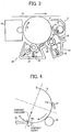
- a first embodiment for the lubricant application unit 47 has a similar configuration as the example except for a contact condition of the photoconductor 8 and the blade 39 as shown in FIG. 6 .
- the blade 39 is in contact with the photoconductor 8 to set such a contact angle as 95 degrees.
- a portion of one side face of the blade 39 is in contact along a surface of the photoconductor 8, by which the blade 39 contacts the photoconductor 8 with a greater contact area (nip) as shown in FIG. 7 compared to a contact area (nip) of the example shown in FIG. 4 , and the contact configuration shown in FIG. 6 and FIG. 7 can reduce or prevent uneven contact phenomenon due to vibration.
- the blade 39 can effectively screen lubricant coming to the contact point of the blade 39 and the photoconductor 8. Accordingly, a phenomenon of lubricant passing through at the contact point of the blade 39 can be prevented effectively. Such an effect will be described later with respect to evaluation tests described later.
- the blade 39 can effectively trap remaining toner passing the cleaning blade 31, and thereby an occurrence of an abnormal image due to such remaining toner can be reduced or prevented.
- the evaluation test was conducted by using an image forming apparatus "Imagio MP C4500," a product of Ricoh Company, and the lubricant application unit 47 having different conditions as set in the following Examples and Comparative Examples.
- the photoconductor 8 having a diameter of 40 mm was rotated with a linear velocity of 205 mm/sec, and the lubricant of zinc stearate was used.
- Two A4-size sheets were fed for an image forming process as one set, and a total of 80,000 sheets were fed for image forming processes while feeding two A4-size sheets with a given interval. After the 80,000 sheets of image forming processes, a contamination amount of the charge roller 9 was evaluated. In the test, the charge roller 9 was disposed at a downstream side a surface moving direction of the photoconductor 8 with respect to the lubricant application unit 47.
- the cleaning roller 37 for cleaning the charge roller 9 was removed from the lubricant application unit 47, and 200 sheets were fed for continuous image forming. After the 200 sheets of image forming process, a contamination amount of the charge roller 9 was evaluated.
- a testing person checked whether a curling had occurred to the contact area 39a of the blade 39 by a visual inspection.
- a testing person checked whether a screaming sound had occurred by ear.
- the configuration of the lubricant application unit 47 for Example 1 was similar to the example, and the blade 39 had a JIS-A hardness of 70 degrees, and a contact angle of 85 degrees.
- the configuration of the lubricant application unit 47 for Example 2 was similar to the example, and the blade 39 had a JIS-A hardness of 73 degrees, and a contact angle of 85 degrees.
- the configuration of the lubricant application unit 47 for Example 3 was similar to the first embodiment, and the blade 39 had a JIS-A hardness of 73 degrees, and a contact angle of 90 degrees.
- the configuration of the lubricant application unit 47 for Example 4 was similar to the first embodiment, and the blade 39 had a JIS-A hardness of 73 degrees, and a contact angle of 95 degrees.
- the configuration for Comparative Example 1 includes one blade 50 for cleaning, and smoothing lubricant.
- the one blade 50 was made of a material of polyurethane rubber, and had a JIS-A hardness of 73 degrees.
- the one blade 50 contacted the photoconductor 8 at its edge portion with an angle of 82 degrees, had a thickness of 1.8 mm, a width of 326 mm, a length of 11.5 mm, and a free end length of 7.6 mm.
- the one blade 50 was in contact with the photoconductor 8 in a counter-direction configuration.
- Comparative Example 1 The configuration for Comparative Example 1 was used for Comparative Example 2 except the one blade 50 was in contact with the photoconductor 8 in a counter-direction configuration with a contact angle of 84 degrees.
- the configuration of the lubricant application unit 47 for Comparative Example 3 was similar to the example, but the blade 39 was in contact with a trailing-direction configuration (not a counter-direction configuration) as shown in FIG. 9 , and the blade 39 had a JIS-A hardness of 84 degree and a contact angle of 5 degrees.
- the configuration of the lubricant application unit 47 for Comparative Example 4 was similar to the example, and the blade 39 had a JIS-A hardness of 73 degrees, and a contact angle of 82 degrees.
- the configuration of the lubricant application unit 47 for Comparative Example 4 was similar to the example, and the blade 39 had a JIS-A hardness of 73 degrees, and a contact angle of 97 degrees.
- Table 1 shows test results of Examples 1 to 4 and Comparative Examples 1 to 5.
- lubricant was supplied to a surface of the photoconductor 8 at an upstream side of a surface movement direction of the photoconductor 8 with respect to the one blade 50.
- the one blade 50 was used to uniformly smooth lubricant supplied on a surface of the photoconductor 8. Therefore, without another device for smoothing lubricant, lubricant supplied on a surface of the photoconductor 8 can be uniformly smoothed by the one blade 50.
- lubricant may enter a contact point of the one blade 50 with remaining toner, by which a lubricant amount on the photoconductor 8 may vary because some area on the photoconductor 8 has remaining toner and some area on the photoconductor 8 has no remaining toner, by which the one blade 50 may not uniformly smooth the lubricant, and thereby a lubricant amount on the photoconductor 8 may vary.
- some areas on the photoconductor 8 may have too much lubricant, and some areas on the photoconductor 8 may have too little lubricant.
- lubricant may stick to remaining toner and then may be removed or cleaned with remaining toner. Accordingly, a lubricant supplying amount and consumption amount was not controlled well in Comparative Examples 1 and 2.
- Comparative Example 2 the one blade 50 and a surface of the photoconductor 8 had a greater contact area compared to Comparative Example 1, by which a contact pressure of the one blade 50 and a surface of the photoconductor 8 might become small. Accordingly, a cleaning performance became lower in Comparative Example 2.
- the blade 39 was in contact with a surface of the photoconductor 8 in a trailing direction, by which an amount of lubricant that passed through the blade 39 might become larger, which might be an inadequate amount.
- the blade 39 was positioned under the photoconductor 8 in a trailing direction and under the photoconductor 8 in a gravitation direction in Comparative Example 3.
- a position of the blade 39 is set under the rotation center of photoconductor 8 in a gravitation direction. Accordingly, lubricant or toner may accumulate on the blade 39, and such accumulated materials may stick to the charge roller 9 disposed at a downstream side of a surface movement direction of the photoconductor 8, by which an abnormal image may occur.
- Comparative Example 5 the contact angle of the blade 39 and a surface of the photoconductor 8 was 97 degrees, which was large compared to Examples 2 to Example 4, and a contact area (nip) of the blade 39 and the photoconductor 8 was large. Accordingly, uneven contact phenomenon due to vibration might be reduced, by which lubricant, remaining toner, or the like might not pass through the blade 39. Further as similar to Examples 2 to 4, a curling phenomenon was prevented or reduced and a cleaning performance was good in Comparative Example 5.
- the blade 39 used for the lubricant application unit 47 made of a material of polyurethane rubber, having a JIS-A hardness of 73 or more, and contacting a surface of the photoconductor 8 in a counter direction of a surface movement direction of the photoconductor 8 with a contact angle of from 85 degrees to 95 degrees can maintain a good level of cleaning performance of the blade 39, can reduce passing through of lubricant or remaining toner, can reduce screaming sound, and can prevent curling. Accordingly, the blade 39 can maintain its performance at a good level over time.
- the lubricant application unit 47 includes the brush roller 33 for applying lubricant to a surface of the photoconductor 8, moving in a given direction, and the blade 39 contacting a surface of the photoconductor 8 in a counter direction of surface movement direction of the photoconductor 8.
- the blade 39 uniformly smoothes lubricant applied on a surface of the photoconductor 8.
- the blade 39 contacts a surface of the photoconductor 8 at the contact area 39a, and an edge face of the blade 39 has an angle of 85 degrees or more with a tangent line extended from a contact portion of the contact area 39a and a surface of the photoconductor 8. Preferably, such angle may be 90 degrees.
- the contact angle may be 85 degrees or more, the blade 39 and a surface of the photoconductor 8 have a contact area that is large enough for reducing lubricant amount passing through the blade 39.
- the blade 39 can control a lubricant amount supplied on the photoconductor 8 at a preferable level.
- the contact angle defined by the tangent line and the edge face of the blade 39 can be set from 85 degrees to 95 degrees, and in the first embodiment from 90 degrees to 95 degrees, by which a contact area of the blade 39 and a surface of the photoconductor 8 can be set great, and thereby a passing through phenomenon of lubricant or toner at the blade 39, which may happen at a given interval or sporadically, can be reduced.
- the blade 39 is in contact with a surface of the photoconductor 8 by contacting the contacting area 39a along the surface of the photoconductor 8.
- a contacting configuration can enlarge a contact area of the blade 39 and the photoconductor 8 compared to contacting only an edge of the contact area 39a to a surface of the photoconductor 8. Accordingly, passing through phenomenon of lubricant or toner at the blade 39, which may happen at a given interval or sporadically, can be reduced.
- the blade 39 has a JIS-A hardness of 73 degrees to enhance a blade strength, by which curling at the contact area 39a can be reduced or prevented.
- the blade 39 is positioned under the rotation center of the photoconductor 8 in a gravitation direction in a counter direction with respect to a surface movement direction of the photoconductor 8, by which lubricant or toner may not accumulate on an edge face of the blade 39. Accordingly, the charge roller 9 disposed at a downstream side of a surface movement direction of the photoconductor 8 may not have lubricant or toner (or accumulated materials) stick thereto, and thereby an abnormal image due to accumulated materials sticking on the charge roller 9 can be reduced or prevented.
- the process cartridge 23 integrally includes the photoconductor 8, the lubricant application unit 47 and at least one of the development unit 10, the first cleaning unit 11, or the charge roller 9, and the process cartridge 23 is detachably mountable to the image forming apparatus 1.
- the lubricant application unit 47 can be used to reduce passing through of lubricant or toner at the blade 39, which may happen at a given interval or sporadically, by which a contamination of the charge roller 9 by lubricant or toner can be reduced, and thereby formation of an abnormal image can be reduced.
- the lubricant application unit 47 includes a configuration reducing a blade curling, by which the lubricant application unit 47 can maintain a good performance over time.
- the image forming apparatus includes the first cleaning unit 11 for cleaning adhered materials adhered on the photoconductor 8, and the lubricant application unit 47 for applying lubricant on the photoconductor 8.
- the lubricant application unit 47 can be used to reduce passing through of lubricant or toner at the blade 39, which may happen at a given interval or sporadically, by which a contamination of the charge roller 9 by lubricant or toner can be reduced, and thereby formation of an abnormal image can be reduced.
- the lubricant application unit 47 includes a configuration reducing a blade curling, by which the lubricant application unit 47 may have a good performance over time.
- the image forming apparatus includes the process cartridge 23, which integrally includes the photoconductor 8, the lubricant application unit 47, and at least one of the development unit 10, the first cleaning unit 11, or the charge roller 9, and the process cartridge 23 may be detachably mountable to the image forming apparatus 1.
- the lubricant application unit 47 can be used to reduce passing through of lubricant or toner at the blade 39, which may happen at a given interval or sporadically, by which a contamination of the charge roller 9 by lubricant or toner can be reduced, and thereby formation of an abnormal image can be reduced.
- the lubricant application unit 47 includes a configuration reducing a blade curling, by which the lubricant application unit 47 can maintain a good performance over the time. Furthermore, a maintenance work or the like can be conducted easily for the lubricant application unit 47 or the like disposed in the process cartridge 23.
Landscapes
- Physics & Mathematics (AREA)
- General Physics & Mathematics (AREA)
- Cleaning In Electrography (AREA)
Claims (6)
- Cartouche de traitement (23) pouvant être fixée de manière amovible à un appareil de formation d'image (1), comprenant :un élément de transport d'image (8) conçu pour se déplacer dans une direction de déplacement de surface prédéterminée ;un appareil d'application de lubrifiant (47) ; etune unité de développement (10), une unité de nettoyage (11) et/ou un dispositif de charge (9),la cartouche de traitement (23) supportant solidairement l'appareil d'application de lubrifiant (47), l'élément de transport d'image (8), et ladite unité de développement (10), ladite unité de nettoyage (11) et/ou ledit dispositif de charge (9),l'appareil d'application de lubrifiant (47) comprenant :un rouleau à brosse d'application de lubrifiant (33) conçu pour appliquer un lubrifiant à l'élément de transport d'image (8) ;une lame élastique (39) qui est conçue pour entrer en contact avec l'élément de transport d'image (8) dans une direction inverse par rapport à une direction de déplacement de surface de l'élément de transport d'image (8), et conçue pour aplanir le lubrifiant appliqué sur l'élément de transport d'image (8),la lame élastique (39) étant en contact avec l'élément de transport d'image (8) au niveau d'une zone de contact (39a) de la lame élastique (39), dans la direction inverse, avec un angle de contact, l'angle de contact étant défini par une face de bord de la lame élastique (39) et une ligne tangente, s'étendant depuis un point de contact de la zone de contact (39a) et une surface de l'élément de transport d'image (8), la lame élastique (39) étant supportée dans une position sur un côté aval de la direction de déplacement de surface de l'élément de transport d'image (8) par rapport à la zone de contact (39a) de la lame élastique (39),l'unité de nettoyage (11) comprenant une lame de nettoyage (31), la lame de nettoyage (31) étant supportée dans une position sur un côté aval de la direction de déplacement de surface de l'élément de transport d'image (8) et conçue pour entrer en contact avec la surface de l'élément de transport d'image (8) dans la configuration de direction inverse,l'appareil d'application de lubrifiant (47) étant positionné entre l'unité de nettoyage (11) et le dispositif de charge (9),caractérisée en ce que la lame élastique (39) est conçue pour entrer en contact avec la surface de l'élément de transport d'image (8) avec un angle de contact allant de 90 à 95 degrés, une partie d'une face latérale de la lame élastique (39) étant en contact sur la surface de l'élément de transport d'image (8) de manière que la zone de contact (39a) de la lame élastique (39) et de l'élément de transport d'image (8) est élargie par rapport à la mise en contact de seulement un bord de la zone de contact (39a) avec une surface de l'élément de transport d'image (8).
- Cartouche de traitement (23) selon la revendication 1, dans laquelle l'angle de contact est de 90 degrés.
- Cartouche de traitement (23) selon la revendication 1, dans laquelle la lame élastique (39) entre en contact avec l'élément de transport d'image (8) avec une face latérale de la lame élastique (39) adjacente à la zone de contact (39a).
- Cartouche de traitement (23) selon la revendication 1, dans laquelle la lame élastique (39) présente une dureté JIS-A de 73 degrés.
- Cartouche de traitement (23) selon la revendication 1, dans laquelle la lame élastique (39) est disposée sous un centre de rotation de l'élément de transport d'image (8) dans une direction de gravitation.
- Appareil de formation d'image (1), comprenant :
la cartouche de traitement (23) selon l'une quelconque des revendications 1 à 5.
Applications Claiming Priority (1)
| Application Number | Priority Date | Filing Date | Title |
|---|---|---|---|
| JP2007291573A JP5073454B2 (ja) | 2007-11-09 | 2007-11-09 | 潤滑剤塗布装置、プロセスカートリッジ及び画像形成装置 |
Publications (3)
| Publication Number | Publication Date |
|---|---|
| EP2058711A2 EP2058711A2 (fr) | 2009-05-13 |
| EP2058711A3 EP2058711A3 (fr) | 2009-06-24 |
| EP2058711B1 true EP2058711B1 (fr) | 2019-04-10 |
Family
ID=40291338
Family Applications (1)
| Application Number | Title | Priority Date | Filing Date |
|---|---|---|---|
| EP08167503.5A Active EP2058711B1 (fr) | 2007-11-09 | 2008-10-24 | Cartouche de procédé avec appareil d'application de lubrifiant et appareil de formation d'images l'utilisant |
Country Status (4)
| Country | Link |
|---|---|
| US (1) | US8103207B2 (fr) |
| EP (1) | EP2058711B1 (fr) |
| JP (1) | JP5073454B2 (fr) |
| CN (1) | CN101430533B (fr) |
Families Citing this family (14)
| Publication number | Priority date | Publication date | Assignee | Title |
|---|---|---|---|---|
| JP5267208B2 (ja) * | 2009-02-25 | 2013-08-21 | 株式会社リコー | クリーニング装置、プロセスカートリッジおよび画像形成装置 |
| JP5505784B2 (ja) * | 2009-03-16 | 2014-05-28 | 株式会社リコー | 画像形成装置 |
| JP5375350B2 (ja) * | 2009-06-12 | 2013-12-25 | 株式会社リコー | クリーニング装置、プロセスカートリッジおよび画像形成装置 |
| JP5471171B2 (ja) * | 2009-08-27 | 2014-04-16 | 株式会社リコー | クリーニング装置、プロセスカートリッジ、画像形成装置及び画像形成方法 |
| JP5487866B2 (ja) * | 2009-10-05 | 2014-05-14 | コニカミノルタ株式会社 | クリーニング装置 |
| JP5712553B2 (ja) | 2010-02-22 | 2015-05-07 | 株式会社リコー | 画像形成装置 |
| JP5850301B2 (ja) | 2010-11-04 | 2016-02-03 | 株式会社リコー | 画像形成装置 |
| JP5724407B2 (ja) | 2011-01-27 | 2015-05-27 | 株式会社リコー | 潤滑剤供給装置、プロセスカートリッジ、及び、画像形成装置 |
| JP2012234004A (ja) * | 2011-04-28 | 2012-11-29 | Konica Minolta Business Technologies Inc | 滑剤塗布装置、画像形成装置 |
| JP2012252152A (ja) * | 2011-06-02 | 2012-12-20 | Konica Minolta Business Technologies Inc | 画像形成装置 |
| JP5871191B2 (ja) | 2012-03-19 | 2016-03-01 | 株式会社リコー | 潤滑剤供給装置、画像形成装置およびプロセスカートリッジ |
| JP5984049B2 (ja) | 2012-03-21 | 2016-09-06 | 株式会社リコー | 潤滑剤供給装置、画像形成装置およびプロセスカートリッジ |
| JP5966694B2 (ja) * | 2012-07-05 | 2016-08-10 | コニカミノルタ株式会社 | 潤滑剤塗布装置および画像形成装置 |
| US9207625B2 (en) | 2013-03-13 | 2015-12-08 | Ricoh Company, Ltd. | Lubricant supply device, process unit, image forming apparatus, and process unit manufacturing method |
Family Cites Families (31)
| Publication number | Priority date | Publication date | Assignee | Title |
|---|---|---|---|---|
| JPH11327317A (ja) | 1998-05-15 | 1999-11-26 | Mita Ind Co Ltd | 画像形成装置 |
| JP2000330443A (ja) | 1999-05-21 | 2000-11-30 | Fuji Xerox Co Ltd | 画像形成装置のクリーニング装置 |
| JP2001305907A (ja) | 2000-04-21 | 2001-11-02 | Ricoh Co Ltd | 画像形成装置 |
| JP2003058011A (ja) * | 2001-08-20 | 2003-02-28 | Konica Corp | 画像形成方法及び画像形成装置 |
| JP2003177646A (ja) * | 2001-12-13 | 2003-06-27 | Ricoh Co Ltd | 画像形成装置 |
| JP2004046073A (ja) * | 2002-03-20 | 2004-02-12 | Ricoh Co Ltd | 画像形成方法、画像形成装置及び画像形成装置用プロセスユニット |
| JP2004037583A (ja) | 2002-06-28 | 2004-02-05 | Ricoh Co Ltd | クリーニングブレード、画像形成装置及びプロセスカートリッジ |
| JP2004061855A (ja) * | 2002-07-29 | 2004-02-26 | Konica Minolta Holdings Inc | 画像形成装置 |
| JP2005070276A (ja) * | 2003-08-22 | 2005-03-17 | Ricoh Co Ltd | 画像形成装置、プロセスカートリッジ及びこれらに用いるトナー |
| JP4509519B2 (ja) * | 2003-09-22 | 2010-07-21 | 株式会社リコー | クリーニング装置、プロセスカートリッジ、画像形成装置 |
| JP2005121760A (ja) | 2003-10-15 | 2005-05-12 | Ricoh Co Ltd | クリーニング装置および画像形成装置 |
| JP4339172B2 (ja) | 2004-04-16 | 2009-10-07 | 株式会社リコー | 画像形成方法及び画像形成装置 |
| JP2005266299A (ja) * | 2004-03-18 | 2005-09-29 | Ricoh Co Ltd | クリーニングブレード、クリーニング装置、画像形成装置及びプロセスカートリッジ |
| JP2005321533A (ja) * | 2004-05-07 | 2005-11-17 | Ricoh Co Ltd | 画像形成装置 |
| JP2006251751A (ja) | 2004-07-07 | 2006-09-21 | Ricoh Co Ltd | 潤滑剤塗布装置、プロセスカートリッジ、トナー、および画像形成装置 |
| JP2006030438A (ja) | 2004-07-14 | 2006-02-02 | Ricoh Co Ltd | クリーニング装置、プロセスカートリッジ及び画像形成装置 |
| JP2006047698A (ja) * | 2004-08-04 | 2006-02-16 | Ricoh Co Ltd | 画像形成方法、画像形成装置及び画像形成装置用プロセスカートリッジ |
| JP2006091809A (ja) | 2004-08-23 | 2006-04-06 | Ricoh Co Ltd | クリーニング装置、プロセスカートリッジ、画像形成装置及びトナー |
| JP2006064918A (ja) * | 2004-08-26 | 2006-03-09 | Ricoh Co Ltd | 画像形成方法、画像形成装置及び画像形成装置用プロセスカートリッジ |
| JP4772416B2 (ja) | 2004-11-01 | 2011-09-14 | 株式会社リコー | クリーニング装置、プロセスカートリッジ、および画像形成装置 |
| JP4849794B2 (ja) | 2004-11-12 | 2012-01-11 | 株式会社リコー | 画像形成装置 |
| US20060115286A1 (en) | 2004-11-30 | 2006-06-01 | Takeshi Uchitani | Electrophotographic image forming apparatus, and toner, process cartridge and image forming method therefor |
| RU2346317C2 (ru) | 2004-12-10 | 2009-02-10 | Рикох Компани, Лимитед | Устройство формирования изображения, приспособление нанесения смазочного материала, приспособление переноса, обрабатывающий картридж и тонер |
| JP4713907B2 (ja) * | 2005-03-17 | 2011-06-29 | 株式会社リコー | 画像形成方法、画像形成装置、及び画像形成装置用プロセスカートリッジ |
| JP4739818B2 (ja) * | 2005-05-31 | 2011-08-03 | 株式会社リコー | クリーニング装置および画像形成装置 |
| JP4819427B2 (ja) * | 2005-07-15 | 2011-11-24 | 株式会社リコー | 画像形成装置、画像形成方法、及びプロセスカートリッジ |
| EP1764661A3 (fr) | 2005-09-14 | 2007-04-18 | Ricoh Company, Ltd. | Applicateur de lubrifiant, appareil de formation d'images et cartouche de traitement utilisant l'applicateur de lubrifiant, et procédé d'assemblage de la cartouche de traitement |
| US20080013998A1 (en) | 2005-09-28 | 2008-01-17 | Naohiro Kumagai | Powder transport unit having enhanced transportability and operability, process cartridge and image forming apparatus using the same |
| JP5005310B2 (ja) | 2006-10-05 | 2012-08-22 | 株式会社リコー | 潤滑剤塗布装置、プロセスカートリッジ及び画像形成装置 |
| JP4995631B2 (ja) * | 2007-05-07 | 2012-08-08 | 株式会社リコー | クリーニング装置、プロセスカートリッジ及び画像形成装置 |
| JP5063291B2 (ja) * | 2007-10-19 | 2012-10-31 | 株式会社リコー | 潤滑剤供給装置、プロセスカートリッジ、画像形成装置、潤滑剤供給部材、及び、サプライ |
-
2007
- 2007-11-09 JP JP2007291573A patent/JP5073454B2/ja active Active
-
2008
- 2008-10-24 EP EP08167503.5A patent/EP2058711B1/fr active Active
- 2008-11-06 US US12/265,844 patent/US8103207B2/en active Active
- 2008-11-10 CN CN2008101745374A patent/CN101430533B/zh active Active
Non-Patent Citations (1)
| Title |
|---|
| None * |
Also Published As
| Publication number | Publication date |
|---|---|
| EP2058711A2 (fr) | 2009-05-13 |
| JP5073454B2 (ja) | 2012-11-14 |
| CN101430533B (zh) | 2012-08-29 |
| JP2009116213A (ja) | 2009-05-28 |
| EP2058711A3 (fr) | 2009-06-24 |
| US20090120356A1 (en) | 2009-05-14 |
| US8103207B2 (en) | 2012-01-24 |
| CN101430533A (zh) | 2009-05-13 |
Similar Documents
| Publication | Publication Date | Title |
|---|---|---|
| EP2058711B1 (fr) | Cartouche de procédé avec appareil d'application de lubrifiant et appareil de formation d'images l'utilisant | |
| US6987944B2 (en) | Cleaning device and image forming apparatus using the cleaning device | |
| JP4933287B2 (ja) | 画像形成装置用潤滑剤塗布装置及びこれを用いたプロセスカートリッジ並びに画像形成装置 | |
| EP1617297B1 (fr) | Procédé et appareil pour le développement d'image capables de former de manière efficace une couche d'agent de développement régulière | |
| US7587164B2 (en) | Cleaning device, image carrier unit and image-forming apparatus | |
| US6778797B2 (en) | Charging roller having elastic member | |
| US20080152378A1 (en) | Image forming apparatus and process cartridge | |
| EP2657787B1 (fr) | Dispositif de développement, cartouche de traitement et appareil de formation d'images | |
| JP4621434B2 (ja) | 画像形成装置 | |
| JP4366067B2 (ja) | 現像装置、プロセスカートリッジ及び画像形成装置 | |
| JP4866585B2 (ja) | 潤滑剤塗布装置及び潤滑剤塗布装置を有するプロセスカートリッジ並びに画像形成装置 | |
| EP0984340B1 (fr) | Appareil de formation d'images et unité de traitement avec un dispositif de nettoyage | |
| KR100624498B1 (ko) | 대전 장치 및 이를 사용한 화상 형성 장치 | |
| JP2017181811A (ja) | 現像装置、プロセスカートリッジ及び画像形成装置 | |
| JP4376053B2 (ja) | 画像形成装置 | |
| JP2007086321A (ja) | 潤滑剤塗布・クリーニングユニット、プロセスカートリッジ及び画像形成装置 | |
| JP2006119304A (ja) | 画像形成装置 | |
| JP2001337558A (ja) | 潤滑剤塗布装置および画像形成装置 | |
| US20050141923A1 (en) | Image forming apparatus | |
| JP4354348B2 (ja) | 帯電装置、プロセスカートリッジ及び画像形成装置 | |
| JP2005134776A (ja) | 画像形成装置 | |
| JP2000242135A (ja) | 画像形成装置 | |
| JP2005077717A (ja) | 画像形成装置 | |
| JP3883362B2 (ja) | 画像形成装置 | |
| JP4402910B2 (ja) | クリーニング装置及び該クリーニング装置を用いたプロセスカートリッジ並びに画像形成装置 |
Legal Events
| Date | Code | Title | Description |
|---|---|---|---|
| PUAI | Public reference made under article 153(3) epc to a published international application that has entered the european phase |
Free format text: ORIGINAL CODE: 0009012 |
|
| AK | Designated contracting states |
Kind code of ref document: A2 Designated state(s): AT BE BG CH CY CZ DE DK EE ES FI FR GB GR HR HU IE IS IT LI LT LU LV MC MT NL NO PL PT RO SE SI SK TR |
|
| AX | Request for extension of the european patent |
Extension state: AL BA MK RS |
|
| PUAL | Search report despatched |
Free format text: ORIGINAL CODE: 0009013 |
|
| AK | Designated contracting states |
Kind code of ref document: A3 Designated state(s): AT BE BG CH CY CZ DE DK EE ES FI FR GB GR HR HU IE IS IT LI LT LU LV MC MT NL NO PL PT RO SE SI SK TR |
|
| AX | Request for extension of the european patent |
Extension state: AL BA MK RS |
|
| 17P | Request for examination filed |
Effective date: 20091002 |
|
| AKX | Designation fees paid |
Designated state(s): DE FR GB |
|
| 17Q | First examination report despatched |
Effective date: 20120531 |
|
| GRAP | Despatch of communication of intention to grant a patent |
Free format text: ORIGINAL CODE: EPIDOSNIGR1 |
|
| INTG | Intention to grant announced |
Effective date: 20181112 |
|
| GRAS | Grant fee paid |
Free format text: ORIGINAL CODE: EPIDOSNIGR3 |
|
| GRAA | (expected) grant |
Free format text: ORIGINAL CODE: 0009210 |
|
| AK | Designated contracting states |
Kind code of ref document: B1 Designated state(s): DE FR GB |
|
| REG | Reference to a national code |
Ref country code: GB Ref legal event code: FG4D |
|
| REG | Reference to a national code |
Ref country code: DE Ref legal event code: R096 Ref document number: 602008059653 Country of ref document: DE |
|
| REG | Reference to a national code |
Ref country code: DE Ref legal event code: R097 Ref document number: 602008059653 Country of ref document: DE |
|
| PLBE | No opposition filed within time limit |
Free format text: ORIGINAL CODE: 0009261 |
|
| STAA | Information on the status of an ep patent application or granted ep patent |
Free format text: STATUS: NO OPPOSITION FILED WITHIN TIME LIMIT |
|
| 26N | No opposition filed |
Effective date: 20200113 |
|
| P01 | Opt-out of the competence of the unified patent court (upc) registered |
Effective date: 20230522 |
|
| PGFP | Annual fee paid to national office [announced via postgrant information from national office to epo] |
Ref country code: GB Payment date: 20231020 Year of fee payment: 16 |
|
| PGFP | Annual fee paid to national office [announced via postgrant information from national office to epo] |
Ref country code: FR Payment date: 20231024 Year of fee payment: 16 Ref country code: DE Payment date: 20231020 Year of fee payment: 16 |