EP2054258B1 - Betätigungsvorrichtung für einen sitz, insbesondere einen kraftfahrzeugsitz - Google Patents
Betätigungsvorrichtung für einen sitz, insbesondere einen kraftfahrzeugsitz Download PDFInfo
- Publication number
- EP2054258B1 EP2054258B1 EP07801662.3A EP07801662A EP2054258B1 EP 2054258 B1 EP2054258 B1 EP 2054258B1 EP 07801662 A EP07801662 A EP 07801662A EP 2054258 B1 EP2054258 B1 EP 2054258B1
- Authority
- EP
- European Patent Office
- Prior art keywords
- actuator
- base
- collar
- bowden cable
- cover
- Prior art date
- Legal status (The legal status is an assumption and is not a legal conclusion. Google has not performed a legal analysis and makes no representation as to the accuracy of the status listed.)
- Active
Links
Images




Classifications
-
- F—MECHANICAL ENGINEERING; LIGHTING; HEATING; WEAPONS; BLASTING
- F16—ENGINEERING ELEMENTS AND UNITS; GENERAL MEASURES FOR PRODUCING AND MAINTAINING EFFECTIVE FUNCTIONING OF MACHINES OR INSTALLATIONS; THERMAL INSULATION IN GENERAL
- F16C—SHAFTS; FLEXIBLE SHAFTS; ELEMENTS OR CRANKSHAFT MECHANISMS; ROTARY BODIES OTHER THAN GEARING ELEMENTS; BEARINGS
- F16C1/00—Flexible shafts; Mechanical means for transmitting movement in a flexible sheathing
- F16C1/10—Means for transmitting linear movement in a flexible sheathing, e.g. "Bowden-mechanisms"
-
- B—PERFORMING OPERATIONS; TRANSPORTING
- B60—VEHICLES IN GENERAL
- B60N—SEATS SPECIALLY ADAPTED FOR VEHICLES; VEHICLE PASSENGER ACCOMMODATION NOT OTHERWISE PROVIDED FOR
- B60N2/00—Seats specially adapted for vehicles; Arrangement or mounting of seats in vehicles
- B60N2/02—Seats specially adapted for vehicles; Arrangement or mounting of seats in vehicles the seat or part thereof being movable, e.g. adjustable
- B60N2/04—Seats specially adapted for vehicles; Arrangement or mounting of seats in vehicles the seat or part thereof being movable, e.g. adjustable the whole seat being movable
- B60N2/12—Seats specially adapted for vehicles; Arrangement or mounting of seats in vehicles the seat or part thereof being movable, e.g. adjustable the whole seat being movable slidable and tiltable
- B60N2/123—Seats specially adapted for vehicles; Arrangement or mounting of seats in vehicles the seat or part thereof being movable, e.g. adjustable the whole seat being movable slidable and tiltable and provided with memory locks
-
- A—HUMAN NECESSITIES
- A47—FURNITURE; DOMESTIC ARTICLES OR APPLIANCES; COFFEE MILLS; SPICE MILLS; SUCTION CLEANERS IN GENERAL
- A47C—CHAIRS; SOFAS; BEDS
- A47C1/00—Chairs adapted for special purposes
- A47C1/02—Reclining or easy chairs
- A47C1/031—Reclining or easy chairs having coupled concurrently adjustable supporting parts
- A47C1/034—Reclining or easy chairs having coupled concurrently adjustable supporting parts the parts including a leg-rest or foot-rest
- A47C1/035—Reclining or easy chairs having coupled concurrently adjustable supporting parts the parts including a leg-rest or foot-rest in combination with movably-coupled seat and back-rest
- A47C1/0355—Reclining or easy chairs having coupled concurrently adjustable supporting parts the parts including a leg-rest or foot-rest in combination with movably-coupled seat and back-rest actuated by linkages, e.g. lazy-tongs mechanisms
-
- B—PERFORMING OPERATIONS; TRANSPORTING
- B60—VEHICLES IN GENERAL
- B60N—SEATS SPECIALLY ADAPTED FOR VEHICLES; VEHICLE PASSENGER ACCOMMODATION NOT OTHERWISE PROVIDED FOR
- B60N2/00—Seats specially adapted for vehicles; Arrangement or mounting of seats in vehicles
- B60N2/24—Seats specially adapted for vehicles; Arrangement or mounting of seats in vehicles for particular purposes or particular vehicles
- B60N2/32—Seats specially adapted for vehicles; Arrangement or mounting of seats in vehicles for particular purposes or particular vehicles convertible for other use
- B60N2/36—Seats specially adapted for vehicles; Arrangement or mounting of seats in vehicles for particular purposes or particular vehicles convertible for other use into a loading platform
- B60N2/366—Seats specially adapted for vehicles; Arrangement or mounting of seats in vehicles for particular purposes or particular vehicles convertible for other use into a loading platform characterised by the locking device
-
- Y—GENERAL TAGGING OF NEW TECHNOLOGICAL DEVELOPMENTS; GENERAL TAGGING OF CROSS-SECTIONAL TECHNOLOGIES SPANNING OVER SEVERAL SECTIONS OF THE IPC; TECHNICAL SUBJECTS COVERED BY FORMER USPC CROSS-REFERENCE ART COLLECTIONS [XRACs] AND DIGESTS
- Y10—TECHNICAL SUBJECTS COVERED BY FORMER USPC
- Y10T—TECHNICAL SUBJECTS COVERED BY FORMER US CLASSIFICATION
- Y10T29/00—Metal working
- Y10T29/49—Method of mechanical manufacture
- Y10T29/49826—Assembling or joining
-
- Y—GENERAL TAGGING OF NEW TECHNOLOGICAL DEVELOPMENTS; GENERAL TAGGING OF CROSS-SECTIONAL TECHNOLOGIES SPANNING OVER SEVERAL SECTIONS OF THE IPC; TECHNICAL SUBJECTS COVERED BY FORMER USPC CROSS-REFERENCE ART COLLECTIONS [XRACs] AND DIGESTS
- Y10—TECHNICAL SUBJECTS COVERED BY FORMER USPC
- Y10T—TECHNICAL SUBJECTS COVERED BY FORMER US CLASSIFICATION
- Y10T74/00—Machine element or mechanism
- Y10T74/20—Control lever and linkage systems
- Y10T74/20396—Hand operated
- Y10T74/20402—Flexible transmitter [e.g., Bowden cable]
- Y10T74/20408—Constant tension sustaining
-
- Y—GENERAL TAGGING OF NEW TECHNOLOGICAL DEVELOPMENTS; GENERAL TAGGING OF CROSS-SECTIONAL TECHNOLOGIES SPANNING OVER SEVERAL SECTIONS OF THE IPC; TECHNICAL SUBJECTS COVERED BY FORMER USPC CROSS-REFERENCE ART COLLECTIONS [XRACs] AND DIGESTS
- Y10—TECHNICAL SUBJECTS COVERED BY FORMER USPC
- Y10T—TECHNICAL SUBJECTS COVERED BY FORMER US CLASSIFICATION
- Y10T74/00—Machine element or mechanism
- Y10T74/20—Control lever and linkage systems
- Y10T74/20396—Hand operated
- Y10T74/20402—Flexible transmitter [e.g., Bowden cable]
- Y10T74/2042—Flexible transmitter [e.g., Bowden cable] and hand operator
-
- Y—GENERAL TAGGING OF NEW TECHNOLOGICAL DEVELOPMENTS; GENERAL TAGGING OF CROSS-SECTIONAL TECHNOLOGIES SPANNING OVER SEVERAL SECTIONS OF THE IPC; TECHNICAL SUBJECTS COVERED BY FORMER USPC CROSS-REFERENCE ART COLLECTIONS [XRACs] AND DIGESTS
- Y10—TECHNICAL SUBJECTS COVERED BY FORMER USPC
- Y10T—TECHNICAL SUBJECTS COVERED BY FORMER US CLASSIFICATION
- Y10T74/00—Machine element or mechanism
- Y10T74/20—Control lever and linkage systems
- Y10T74/20396—Hand operated
- Y10T74/20402—Flexible transmitter [e.g., Bowden cable]
- Y10T74/2042—Flexible transmitter [e.g., Bowden cable] and hand operator
- Y10T74/20426—Slidable
-
- Y—GENERAL TAGGING OF NEW TECHNOLOGICAL DEVELOPMENTS; GENERAL TAGGING OF CROSS-SECTIONAL TECHNOLOGIES SPANNING OVER SEVERAL SECTIONS OF THE IPC; TECHNICAL SUBJECTS COVERED BY FORMER USPC CROSS-REFERENCE ART COLLECTIONS [XRACs] AND DIGESTS
- Y10—TECHNICAL SUBJECTS COVERED BY FORMER USPC
- Y10T—TECHNICAL SUBJECTS COVERED BY FORMER US CLASSIFICATION
- Y10T74/00—Machine element or mechanism
- Y10T74/20—Control lever and linkage systems
- Y10T74/20396—Hand operated
- Y10T74/20402—Flexible transmitter [e.g., Bowden cable]
- Y10T74/2042—Flexible transmitter [e.g., Bowden cable] and hand operator
- Y10T74/20438—Single rotatable lever [e.g., for bicycle brake or derailleur]
-
- Y—GENERAL TAGGING OF NEW TECHNOLOGICAL DEVELOPMENTS; GENERAL TAGGING OF CROSS-SECTIONAL TECHNOLOGIES SPANNING OVER SEVERAL SECTIONS OF THE IPC; TECHNICAL SUBJECTS COVERED BY FORMER USPC CROSS-REFERENCE ART COLLECTIONS [XRACs] AND DIGESTS
- Y10—TECHNICAL SUBJECTS COVERED BY FORMER USPC
- Y10T—TECHNICAL SUBJECTS COVERED BY FORMER US CLASSIFICATION
- Y10T74/00—Machine element or mechanism
- Y10T74/20—Control lever and linkage systems
- Y10T74/20396—Hand operated
- Y10T74/20402—Flexible transmitter [e.g., Bowden cable]
- Y10T74/2045—Flexible transmitter [e.g., Bowden cable] and sheath support, connector, or anchor
-
- Y—GENERAL TAGGING OF NEW TECHNOLOGICAL DEVELOPMENTS; GENERAL TAGGING OF CROSS-SECTIONAL TECHNOLOGIES SPANNING OVER SEVERAL SECTIONS OF THE IPC; TECHNICAL SUBJECTS COVERED BY FORMER USPC CROSS-REFERENCE ART COLLECTIONS [XRACs] AND DIGESTS
- Y10—TECHNICAL SUBJECTS COVERED BY FORMER USPC
- Y10T—TECHNICAL SUBJECTS COVERED BY FORMER US CLASSIFICATION
- Y10T74/00—Machine element or mechanism
- Y10T74/20—Control lever and linkage systems
- Y10T74/20396—Hand operated
- Y10T74/20402—Flexible transmitter [e.g., Bowden cable]
- Y10T74/20462—Specific cable connector or guide
Definitions
- the invention relates to an actuating device for a vehicle with a base part, an aperture of a handle and a Bowden cable, wherein the Bowden cable has an end fitting.
- EP 1 352 779 A1 discloses a control handle assembly for use in a fabric covered vehicle seat.
- the object is achieved with an actuating device for a vehicle according to claim 1.
- the defined starting position of the end fitting it is advantageously possible to mount the handle on the panel, at the same time the end fitting is connected to the handle, without an additional assembly step takes place.
- the assembly of the actuator is made much easier and also the assembly time is shortened.
- a blind assembly between handle and end fitting is possible here.
- the base part has a first collar and the diaphragm has a second collar.
- a clamping gap is formed, in which a reference is clamped during assembly.
- the cover which is preferably a seat cover of a vehicle seat, is thereby positively and / or non-positively connected to the base part and the panel. In essence, the attachment of the cover takes place along a surface, whereby the force on the cover does not punctually attack during mechanical loading, but distributed along the surface. A possible tearing of the cover is thereby prevented.
- the base part has a nose and the cover has a tab with a slot.
- the tab is preferably folded with the slot to the nose and pulled the slot over the nose.
- This additionally creates a fixation of the cover, whereby the reference is positively and / or non-positively connected to the base part.
- a fixation of the cover is achieved relative to the vehicle seat. The fixation is positive and / or non-positive, the reference for this essentially does not need to be specially prepared or manufactured.
- the guide element is designed as a guide rib.
- the guide rib has a defined height and width, wherein the width and the height of the end fitting of the Bowden cable are dependent.
- the Bowden cable is mounted in the base part, with a rotation of the Bowden cable this is rotated by the guide rib in its original orientation, before he on the base part comes to rest. The exact mode of action of the guide element is explained in more detail in the description of the figures.
- the diaphragm has a plug-in part.
- the aperture is advantageously connected to the base part during assembly. Due to the straightforward plug connection while the assembly time is reduced, for example, because no screws tightened or welds must be formed.
- the base part has a chamber and / or a latching hook and / or a latching nose and / or a sleeve.
- the connector of the aperture is preferably inserted during assembly. By Rasthacken while a positive and / or non-positive connection between the male part of the panel and the latching hooks of the base part is achieved.
- the detent latches with the metal structure. This results in a positive and / or non-positive connection between the metal structure and the base part.
- the end fitting is in the direction of the chamber.
- the actuating device is provided in a vehicle seat.
- the actuating device preferably serves as a trigger in order to shift a motor vehicle seat, for example, from a use position into a non-use position.
- a non-use position for example, an easy-entry position of the vehicle seat, in which the Backrest to the seat part folded and the vehicle seat is moved.
- the actuator is also used at other locations in the vehicle, but preferably for unlocking or locking of elements.
- the actuating device is provided for releasing a Wegverstellers.
- the operation of the handle of the Bowden cable is actuated, which preferably unlocks a Recliner and thus allows the adjustment of the vehicle seat.
- the base part is introduced with the sleeve in a metal structure of the vehicle seat.
- the locking lug on the sleeve thereby locked in the metal structure of the vehicle seat, whereby a positive and / or non-positive connection between the base part and the metal structure and thus also with the vehicle seat is formed.
- Through the sleeve of the base part at least one Bowden cable is guided, which comes to rest in the chamber of the base part with its end fitting.
- the reference is drawn over the base part, wherein the reference has a recess which lies over the chamber of the base part.
- the tab of the cover is passed around the inner periphery of the first collar and pushed by means of the slot on the nose of the base part.
- the seat cover is thus positively connected to the base part and fixed to some extent relative to the metal structure.
- the aperture is placed on the base part, wherein the male part of the aperture is inserted into the chamber of the base part.
- the latching hook of the base part locks with the male part, whereby a positive and / or non-positive Connection between the panel and the base part is created.
- the first collar of the base part and the second collar of the panel abut each other, wherein between the first collar and the second collar, a nip is formed, along which the cover is clamped.
- the handle is placed on the panel, wherein the end fitting of the Bowden cable is encompassed by the undercut of the handle and is thereby enclosed by the recess of the Bowdenzug technique and a ramp of the base part.
- FIG. 1 schematically a vehicle seat 3 with an actuating device 1 is shown.
- the actuating device 1 is arranged laterally in the upper region of a backrest 2 of a vehicle seat 3.
- the vehicle seat 3 can be moved from a use position forward in a non-use position shown in dashed lines, in which the backrest 2 is additionally pivoted in a forwardly inclined position.
- FIG. 2 and the FIG. 3 is shown schematically that the actuator 1 in the (only in Fig. 5 illustrated) metal structure 31 of the backrest 2 usable base part 4, an anchored in the base part 4 panel 5 and a rotatable in the aperture 5 arranged handle 6, which are preferably injection molded from plastic.
- the base part 4 consists of a in the installed state down through the metal structure 31 of the backrest 2 projecting sleeve 7, which is latched by a detent 8 in a recess of the metal structure 31 and through which one or more leading to the seat adjusters Bowden cables (in Fig. 5 and 6 provided with reference numerals 25 and 25 ') in the direction of the handle 6 are feasible.
- the sleeve 7 At the upper portion of the sleeve 7 is followed by a sleeve 7 towards open chamber 9, which has a first collar 10 at its upper edge.
- the first collar 10 is recessed like a ring and, in a lateral view, annular. From the inner periphery of the first collar 10, a stabilizing web 11 protrudes toward the metal structure 31, which at the lower region of the first collar 10 projects in the direction of the chamber 9 outstanding nose 12 trains.
- the panel 5 also has an annular circumferential second collar 13. At the second collar 13, a male part 14 is formed, which is inserted into the chamber 9.
- the plug-in part 14 of the panel 5 is further provided with a recessed grip 15 ', which extends over the angle of the second collar 13 away.
- the collars 10 and 13 are formed substantially congruent and lie in inserted into the base part 4 aperture 5 to form a minimum clamping gap 15 almost to each other.
- the reference 16 is shown, which is particularly preferably a seat cover.
- the nip 15 fixes the in FIG. 4 illustrated reference 16, which is pulled after insertion of the base part 4, for example, over the backrest 2.
- the cover 16 has a recess 17 approximately corresponding to the inner circumference of the first collar 10 into which a tab 18 of the cover 16 protrudes.
- the tab 18 is guided around the inner circumference of the first collar 10 and pushed by a slot 19 on the nose 12.
- the cover 16 is thus already positively connected to the base part 4 and thus fixed to a certain extent relative to the metal structure 31 of the backrest 2.
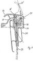
- FIG. 5 schematically shows that the handle 6 is pre-assembled with the aperture 5 pivotally about an axis 21, wherein a Bowdenzuging 22 protrudes into the chamber-like male part 14 of the aperture 5.
- the handle 23 of the handle 6 extends in the unactuated state approximately flush to the upper region of the second collar 13, wherein the operator can grip the handle 23 from the side of the second collar 13 forth in the region of the recessed grip 15 '.
- FIG. 7 is schematically illustrated the base part 4 with the guide member 32.
- the guide member 32 is located between the core 24 of the Bowden cable 25 and prevents the end fitting 26 from twisting. If the Bowden cable 25 is twisted, the pulling of the Bowden cable 25 in the direction of the guide element 32 causes the Bowden cable to rotate back into its actual orientation.
- a correct position of the end fitting 26 is in the lower part of FIG. 7 shown. Essentially only in this position, the end fitting 26 can accumulate due to the guide member 32 to the base part 4.
- the guide element 32 has a defined height and width, which depends on the end fitting 26 and the design of the base part 4.
Landscapes
- Engineering & Computer Science (AREA)
- Mechanical Engineering (AREA)
- Aviation & Aerospace Engineering (AREA)
- Transportation (AREA)
- Health & Medical Sciences (AREA)
- General Engineering & Computer Science (AREA)
- Oral & Maxillofacial Surgery (AREA)
- Dentistry (AREA)
- General Health & Medical Sciences (AREA)
- Seats For Vehicles (AREA)
- Lock And Its Accessories (AREA)
Description
- Die Erfindung betrifft eine Betätigungsvorrichtung für ein Fahrzeug mit einem Basisteil, einer Blende einem Griffstück und einem Bowdenzug, wobei der Bowdenzug ein Endfitting aufweist.
- Solche Betätigungsvorrichtungen sind allgemein bekannt. So beschreibt die europäische Patentschrift
EP 1 352 779 A1 beispielsweise eine Betätigungsvorrichtung für einen Fahrzeugsitz mit einem Griffstück, das einen Zug bewegt. Die Betätigungsvorrichtung wird dabei so an dem Fahrzeugsitz befestigt, dass ein Sitzbezug zwischen zwei Blenden eingeklemmt wird. Hierfür weisen beide Blenden Befestigungsmittel auf, die in den Sitzbezug eingreifen. Nachteilig bei der Betätigungsvorrichtung ist jedoch, dass bei der Montage der Zug umständlich mit dem Griffstück verbunden werden muss. Des Weiteren besteht bei der beschriebenen Betätigungsvorrichtung die Gefahr, dass der Sitzbezug durch das Eingreifen des Befestigungsmittels einreißt, da der Bezug bei der Montage perforiert wird.EP 1 352 779 A1 offenbart eine Steuergriffanordnung zur Verwendung in einem mit Stoff bespannten Fahrzeugsitz. - Es war daher die Aufgabe der vorliegenden Erfindung eine Betätigungsvorrichtung anzugeben, bei dem die Montage eines Bowdenzuges mit einem Griffstück im Wesentlichen in einer Blindmontage erfolgen kann.
- Gelöst wird die Aufgabe mit einer Betätigungsvorrichtung für ein Fahrzeug gemäß Anspruch 1. Durch die definierte Ausgangsposition des Endfittings ist es vorteilhaft möglich, das Griffstück auf der Blende zu montieren, wobei gleichzeitig der Endfitting mit dem Griffstück verbunden wird, ohne dass ein zusätzlicher Montageschritt erfolgt. Hierdurch wird die Montage der Betätigungsvorrichtung wesentliche unkomplizierter gestaltet und zudem wird die Montagezeit verkürzt. Eine Blindmontage zwischen Griffstück und Endfitting ist hierbei möglich.
- Unter einer Blindmontage soll hierbei verstanden werden, wenn beim Einsetzen des Griffstücks in die Betätigungsvorrichtung im Wesentlichen gleichzeitig auch der Bowdenzug mit dem Griffstück verbunden wird, ohne dass in einem weiteren Montageschritt manuelle oder maschinell ein Kontakt zwischen den beiden Teilen hergestellt werden muss. Ein separater Montageschritt, indem der Bowdenzug mit dem Griffstück befestigt wird, entfällt hierbei.
- Bei einer bevorzugten Ausführungsform der Erfindung weist das Basisteil einen ersten Kragen und die Blende einen zweiten Kragen auf. Bei der Montage der Blende mit dem Basisteil entsteht bevorzugt ein Klemmspalt, in dem ein Bezug während der Montage eingeklemmt wird. Der Bezug, der bevorzugt ein Sitzbezug eines Fahrzeugsitzes ist, wird hierdurch form- und/oder kraftschlüssig mit dem Basisteil und der Blende verbunden. Im Wesentlichen erfolgt die Befestigung des Bezuges hierbei entlang einer Fläche, wodurch bei mechanischen Belastungen die Kraft an dem Bezug nicht punktuell angreift, sondern sich entlang der Fläche verteilt. Ein mögliches Einreißen des Bezuges wird hierdurch vorgebeugt.
- Bevorzugt weist das Basisteil eine Nase und der Bezug eine Lasche mit einem Schlitz auf. Bei der Montage wird bevorzugt die Lasche mit dem Schlitz zur Nase hin umgeschlagen und der Schlitz über die Nase gezogen. Hierdurch entsteht zusätzlich eine Fixierung des Bezuges, wodurch der Bezug form- und/oder kraftschlüssig mit dem Basisteil verbunden ist. Sowohl durch das Einklemmen des Bezuges entlang des Klemmspalts als auch durch die Verbindung des Schlitzes mit der Nase des Basisteils, wird eine Fixierung des Bezuges relativ zum Fahrzeugsitz erreicht. Die Fixierung ist form- und/oder kraftschlüssig, wobei der Bezug hierfür im Wesentlichen nicht speziell vorbereitet oder gefertigt werden muss.
- Weiterhin bevorzugt ist das Führungselement als eine Führungsrippe ausgebildet. Die Führungsrippe weist dabei eine definierte Höhe und Breite auf, wobei die Breite und die Höhe von dem Endfitting des Bowdenzuges abhängig sind. Der Bowdenzug wird in das Basisteil montiert, bei einer Verdrehung des Bowdenzuges wird dieser durch die Führungsrippe in seine ursprüngliche Orientierung gedreht, bevor er auf dem Basisteil zu liegen kommt. Die genaue Wirkungsweise des Führungselements wird in der Figurenbeschreibung näher erklärt.
- Bevorzugt weist das Griffstück eine Bowdenzugaufnahme auf und ist um eine Achse drehbar. Die Bowdenzugaufnahme wiederum weist bevorzugt einen Hinterschnitt und/oder eine Einbuchtung auf. Durch den Hinterschnitt und/oder die Einbuchtung wird der Endfitting des Bowdenzuges mit dem Griffstück verbunden. Bevorzugt gelangt dabei der Endfitting in die Einbuchtung, während das Griffstück auf die Blende montiert wird. Die Verbindung zwischen dem Endfitting und dem Griffstück ist dabei sehr robust und unkompliziert in der Fertigung. Bei einer Betätigung des Griffstücks dreht bevorzugt das Griffstück um die Achse und bewegt somit den Bowdenzug. Die genaue Funktionsweise wird in der Figurenbeschreibung erläutert.
- Weiterhin bevorzugt weist die Blende ein Steckteil auf. Mit dem Steckteil wird die Blende in vorteilhafter Weise mit dem Basisteil bei der Montage verbunden. Durch die unkomplizierte Steckverbindung wird dabei weiterhin die Montagezeit herabgesetzt, da beispielsweise keine Schrauben angezogen oder Schweißnähte gebildet werden müssen.
- Bevorzugt weist das Basisteil eine Kammer und/oder einen Rasthaken und/oder eine Rastnase und/oder eine Hülse auf. In die Kammer wird bevorzugt die Steckverbindung der Blende bei der Montage gesteckt. Durch den Rasthacken wird dabei eine form- und/oder kraftschlüssige Verbindung zwischen dem Steckteil der Blende und dem Rasthacken des Basisteils erreicht. Bei dem Einführen des Basisteils in eine Metallstruktur des Fahrzeugsitzes, verrastet die Rastnase mit der Metallstruktur. Hierdurch entsteht eine form- und/oder kraftschlüssige Verbindung zwischen der Metallstruktur und dem Basisteil. In der Hülse wird bevorzugt der Bowdenzug geführt, wobei der Endfitting in Richtung der Kammer liegt.
- Besonders bevorzugt ist die Betätigungsvorrichtung in einem Fahrzeugsitz vorgesehen. Die Betätigungsvorrichtung dient hierbei bevorzugt als Auslöser, um einen Kraftfahrzeugsitz beispielsweise von einer Gebrauchsstellung in eine Nichtgebrauchsstellung zu verlagern. Eine solche Nichtgebrauchsstellung ist beispielsweise eine Easy-Entry-Stellung des Fahrzeugsitzes, bei der die Rückenlehne zum Sitzteil verklappt und der Fahrzeugsitz verfahren ist. Selbstverständlich ist die Betätigungsvorrichtung auch an anderen Stellen im Fahrzeug einsetzbar, bevorzugt jedoch zur Ent- oder Verriegelung von Elementen.
- Weiterhin bevorzugt ist die Betätigungsvorrichtung zum Lösen eines Sitzverstellers vorgesehen. Hierbei wird durch die Betätigung des Griffstücks der Bowdenzug betätigt, der bevorzugt einen Recliner entriegelt und so die Verstellung des Fahrzeugsitzes ermöglicht.
- Vier Verfahren zur Montage der Betätigungsvorrichtung und ein Verfahren zur Betätigung der Betätigungsvorrichtung sind ebenfalls Gegenstand der vorliegenden Erfindung.
- Bei einem ersten Verfahren zur Montage der Betätigungsvorrichtung wird erfindungsgemäß das Basisteil mit der Hülse in eine Metallstruktur des Fahrzeugsitzes eingeführt. Die Rastnase an der Hülse verrastet dabei in der Metallstruktur des Fahrzeugsitzes, wodurch eine form- und/oder kraftschlüssige Verbindung zwischen dem Basisteil und der Metallstruktur und somit auch mit dem Fahrzeugsitz entsteht. Durch die Hülse des Basisteils wird mindestens ein Bowdenzug geführt, der in der Kammer des Basisteils mit seinem Endfitting zu liegen kommt.
- Bei einem zweiten Verfahren zur Montage der Betätigungsvorrichtung wird erfindungsgemäß der Bezug über das Basisteil gezogen, wobei der Bezug eine Ausnehmung aufweist, die über der Kammer des Basisteils liegt. Die Lasche des Bezuges wird um den Innenumfang des ersten Kragens herumgeführt und mittels des Schlitzes auf die Nase des Basisteils geschoben. Der Sitzbezug ist somit formschlüssig mit dem Basisteil verbunden und in gewissem Umfang relativ zur Metallstruktur fixiert.
- Bei einem dritten Verfahren zur Montage der Betätigungsvorrichtung wird erfindungsgemäß die Blende auf das Basisteil gesetzt, wobei das Steckteil der Blende in die Kammer des Basisteils eingeführt wird. Hierbei verrastet der Rasthaken des Basisteils mit dem Steckteil, wodurch eine form- und/oder kraftschlüssige Verbindung zwischen der Blende und dem Basisteil entsteht. Der erste Kragen des Basisteils und der zweite Kragen der Blende liegen aneinander, wobei zwischen dem ersten Kragen und dem zweiten Kragen ein Klemmspalt entsteht, entlang dem der Bezug festgeklemmt wird.
- Bei einem vierten Verfahren zur Montage der Betätigungsvorrichtung wird erfindungsgemäß das Griffstück auf die Blende gesetzt, wobei der Endfitting des Bowdenzuges von dem Hinterschnitt des Griffstückes umgriffen wird und hierdurch von der Einbuchtung der Bowdenzugaufnahme und einer Rampe des Basisteils umschlossen wird. Eine extra Montageschritt, in dem der Endfitting mit der Bowdenzugaufnahme verbunden wird, ist nicht nötig.
- Bei einem Verfahren zur Betätigung der Betätigungsvorrichtung wird bevorzugt das Griffstück mit einer Handhabe um die Achse verschwenkt, wobei hierbei der Endfitting, der sich in der Einbuchtung des Griffstücks befindet, entlang der Rampe geführt wird. Hierdurch wird bevorzugt die Seele des Bowdenzuges verschoben und ein Sitzversteller gelöst.
- Die Erfindung und die bevorzugte Ausführungsform werden anhand von Figuren näher beschrieben. Die Beschreibungen sind dabei lediglich beispielhaft und schränken den allgemeinen Erfindungsgedanken nicht ein.
- Figur 1
- stellt schematisch einen Fahrzeugsitz mit einer Betätigungsvorrichtung dar.
- Figur 2
- stellt schematisch ein Basisteil, eine Blende und ein Griffstück dar.
- Figur 3
- stellt schematisch das Basisteil mit der Blende dar.
- Figur 4
- stellt schematisch einen Bezug dar.
- Figur 5
- stellt schematisch die Betätigungsvorrichtung dar.
- Figur 6
- stellt schematisch eine Aufsicht auf die Betätigungsvorrichtung dar.
- Figur 7
- stellt das Basisteil mit einem Führungselement und einem Endfitting dar.
- In der
Figur 1 ist schematisch ein Fahrzeugsitz 3 mit einer Betätigungsvorrichtung 1 dargestellt. Hierbei ist die Betätigungsvorrichtung 1 seitlich im oberen Bereich einer Rückenlehne 2 eines Fahrzeugsitzes 3 angeordnet. Nach der manuellen Handhabung der Betätigungseinrichtung 1 kann der Fahrzeugsitz 3 aus einer Gebrauchsstellung nach vorne in eine gestrichelt dargestellte Nichtgebrauchsstellung verschoben werden, in der die Rückenlehne 2 zusätzlich in eine nach vorne geneigte Position verschwenkt ist. - In der
Figur 2 und derFigur 3 ist schematisch dargestellt, dass die Betätigungsvorrichtung 1 ein in die (nur inFig. 5 dargestellte) Metallstruktur 31 der Rückenlehne 2 einsetzbares Basisteil 4, eine im Basisteil 4 verankerbare Blende 5 und ein in der Blende 5 drehbar angeordnetes Griffstück 6 umfasst, die vorzugsweise aus Kunststoff spritzgegossen werden. Das Basisteil 4 besteht aus einem im Einbauzustand nach unten durch die Metallstruktur 31 der Rückenlehne 2 ragenden Hülse 7, die mittels einer Rastnase 8 in einer Ausnehmung der Metallstruktur 31 verrastbar ist und durch welche ein oder mehrere zu den Sitzverstellern führende Bowdenzüge (inFig. 5 und6 mit Bezugszeichen 25 bzw. 25' versehen) in Richtung des Griffstücks 6 führbar sind. An den oberen Bereich der Hülse 7 schließt sich eine zur Hülse 7 hin offene Kammer 9 an, die an ihrer Oberkante einen ersten Kragen 10 aufweist. Der erste Kragen 10 ist ringartig ausgenommen und, in seitlicher Ansicht, ringförmig ausgebildet. Mit dieser ringförmigen Ausbildung umgreift das Basisteil 4 später den oberen und seitlichen Holm der Metallstruktur 31 der Rückenlehne 2. Vom Innenumfang des ersten Kragens 10 ragt ein stabilisierender Steg 11 zur Metallstruktur 31 hin, welcher am unteren Bereich des ersten Kragens 10 eine in Richtung der Kammer 9 herausragende Nase 12 ausbildet. Die Blende 5 weist ebenfalls einen ringförmigen umlaufenden zweiten Kragen 13 auf. An den zweiten Kragen 13 ist ein Steckteil 14 angeformt, welches in die Kammer 9 einführbar ist. - Das Steckteil 14 der Blende 5 ist ferner mit einer Griffmulde 15' ausgestattet, welche sich über den Winkel des zweiten Kragens 13 hinweg erstreckt. Die Kragen 10 und 13 sind im Wesentlichen deckungsgleich ausgebildet und liegen bei in das Basisteil 4 eingesetzter Blende 5 unter Ausbildung eines minimalen Klemmspalts 15 nahezu aneinander an.
- In der
Figur 4 ist schematisch der Bezug 16 dargestellt, der besonders bevorzugt ein Sitzbezug ist. Der Klemmspalt 15 fixiert den inFigur 4 isoliert dargestellten Bezug 16, der nach dem Einsetzen des Basisteils 4 beispielsweise über die Rückenlehne 2 gezogen wird. Der Bezug 16 weist eine etwa dem Innenumfang des ersten Kragens 10 entsprechende Ausnehmung 17 auf, in welche eine Lasche 18 des Bezugs 16 ragt. Die Lasche 18 wird um den Innenumfang des ersten Kragens 10 herumgeführt und mittels eines Schlitzes 19 auf die Nase 12 aufgeschoben. Der Bezug 16 ist damit bereits formschlüssig mit dem Basisteil 4 verbunden und damit auch in gewissem Umfang relativ zur Metallstruktur 31 der Rückenlehne 2 fixiert. Beim Einsetzen der Blende 5 in das Basisteil 4 wird diese durch im Basisteil 4 vorgesehene Rasthacken 20 in Position gehalten, wobei der Bezug 16 um die Ausnehmung 17 herum im Klemmspalt 15 kraftschlüssig und partiell durch Anlage an der Griffmulde 15' sowie dem Steckteil 14 auch formschlüssig gehalten wird. - Die
Figur 5 stellt schematisch dar, dass das Griffstück 6 vormontiert mit der Blende 5 um eine Achse 21 schwenkbar angeordnet ist, wobei eine Bowdenzugaufnahme 22 in das kammerartig ausgebildete Steckteil 14 der Blende 5 hineinragt. Die Handhabe 23 des Griffstücks 6 verläuft in unbetätigtem Zustand etwa bündig zum oberen Bereich des zweiten Kragens 13, wobei der Bediener die Handhabe 23 von der Seite des zweiten Kragens 13 her im Bereich der Griffmulde 15' untergreifen kann. Wie weiterhin ausFigur 5 ersichtlich, liegt der tonnenförmige, an die Seele 24 des Bowdenzugs 25 angeformte Endfitting 26 parallel zur Achse 21 auf einer kreisbogenförmigen Rampe 27 auf, welche äquidistant zur Achse 21 verläuft. Beim Einsetzen von Blende 5 und Griffstück 6 wird der Endfitting 26 von einer mit Hinterschnitten 28, 29 versehenen Einbuchtung 30 der Bowdenzugaufnahme 22 umgriffen und ist nachfolgend von der Einbuchtung 30 und der Rampe 27 umschlossen. Beim Hochschwenken der Handhabe 23 wird der Endfitting 26 entlang der Rampe 27 nach oben geführt (in dieser Position als Handhabe 23' und Endfitting 26' bezeichnet). Hierdurch werden die Seele 24 im Bowdenzug 25 verschoben und ein Sitzversteller gelöst. Bei einer ersten Montage der Betätigungsvorrichtung 1 muss lediglich die Handhabe 23 auf die Blende 5 geklappt werden, bzw. das Griffstück 6 auf die Blende 5 montiert werden, damit der Endfitting 26 mit dem Griffstück 6 verbunden ist. Die Montage des Bowdenzuges 25 mit dem Griffstück 6 erfolgt folglich in einer Blindmontage. Ein separater Montageschritt, bei dem manuell oder maschinell eine Verbindung zwischen dem Griffstück 6 und dem Endfitting 26 hergestellt wird, ist nicht notwendig. - Wie schematisch aus der Aufsicht auf das Basisteil 4 nach
Figur 6 ersichtlich, ist durch diese Ausbildung eine Doppelanordnung von Bowdenzügen 25, 25' betätigbar, die einen gemeinsamen Endfitting 26 aufweisen. - In der
Figur 7 ist schematisch das Basisteil 4 mit dem Führungselement 32 dargestellt. Das Führungselement 32 befindet sich zwischen die Seele 24 des Bowdenzuges 25 und verhindert, dass sich der Endfitting 26 verdreht. Ist der Bowdenzug 25 verdreht, so bewirkt das Ziehen des Bowdenzuges 25 in Richtung des Führungselements 32, dass sich der Bowdenzug wieder in seine eigentliche Orientierung dreht. Eine richtige Position des Endfittings 26 ist im unteren Teil derFigur 7 dargestellt. Im Wesentlichen nur in dieser Position kann sich das Endfitting 26 auf Grund des Führungselements 32 an das Basisteil 4 anlagern. Das Führungselement 32 weist dabei eine definierte Höhe und Breite auf, die von dem Endfitting 26 und der Gestaltung des Basisteils 4 abhängt. -
- 1
- Betätigungsvorrichtung
- 2
- Rückenlehne
- 3
- Kraftfahrzeugsitz
- 4
- Basisteil
- 5
- Blende
- 6
- Griffstück
- 7
- Hülse
- 8
- Rastnase
- 9
- Kammer
- 10
- erster Kragen (Basisteil)
- 11
- Steg
- 12
- Nase
- 13
- zweiter Kragen (Blende)
- 14
- Steckteil
- 15
- Klemmspalt
- 15'
- Griffmulde
- 16
- Bezug
- 17
- Ausnehmung
- 18
- Lasche
- 19
- Schlitz
- 20
- Rasthaken
- 21
- Achse
- 22
- Bowdenzugaufnahme
- 23, 23'
- Handhabe
- 24
- Seele (des Bowdenzugs)
- 25
- Bowdenzug
- 26, 26
- Endfitting
- 27
- Rampe
- 25 28, 29
- Hinterschnitt
- 30
- Einbuchtung
- 31
- Metallstruktur
Claims (14)
- Betätigungsvorrichtung (1) für ein Fahrzeug mit einem Basisteil (4), einer Blende (5), einem Griffstück (6) und einem Bowdenzug (25), wobei der Bowdenzug (25) ein Endfitting (26) aufweist, dadurch gekennzeichnet, dass das Basisteil (4) ein Führungselement (32) aufweist, das das Endfitting (26) des Bowdenzugs (25) in eine definierte Ausgangsposition für die Montage des Griffstücks (6) mit dem Endfitting (26) überführt.
- Betätigungsvorrichtung (1) nach Anspruch 1 , dadurch gekennzeichnet, dass das Basisteil (4) einen ersten Kragen (10) und die Blende (5) einen zweiten Kragen (13) aufweist, wobei zwischen dem ersten Kragen (10) und dem zweiten Kragen (13) bei der Montage ein Klemmspalt (15) entsteht und im Klemmspalt (15) ein Bezug (16) eingeklemmt ist.
- Betätigungsvorrichtung (1) nach Anspruch 2, dadurch gekennzeichnet, dass das Basisteil (4) eine Nase (12) und der Bezug (16) eine Lasche (18) mit einem Schlitz (19) aufweist und der Schlitz (19) mit der Nase (12) eine form- und/oder kraftschlüssige Verbindung eingeht.
- Betätigungsvorrichtung (1) nach einem der vorhergehenden Ansprüche, dadurch gekennzeichnet, dass das Führungselement (32) eine Führungsrippe ist.
- Betätigungsvorrichtung (1) nach einem der vorhergehenden Ansprüche, dadurch gekennzeichnet, dass das Griffstück (6) eine Bowdenzugaufnahme (22) mit einem Hinterschnitt (28, 29) und/oder einer Einbuchtung (30) aufweist und um eine Achse (21) schwenkbar ist.
- Betätigungsvorrichtung (1) nach einem der vorhergehenden Ansprüche, dadurch gekennzeichnet, dass die Blende (5) ein Steckteil (14) aufweist.
- Betätigungsvorrichtung (1) nach einem der vorhergehenden Ansprüche, dadurch gekennzeichnet, dass das Basisteil (4) eine Kammer (9) und/oder einen Rasthaken (20) und/oder eine Rastnase (8) und/oder eine Hülse (7) aufweist.
- Betätigungsvorrichtung (1) nach einem der vorhergehenden Ansprüche, dadurch gekennzeichnet, dass sie in einem Fahrzeugsitz vorgesehen ist.
- Betätigungsvorrichtung (1) nach einem der vorhergehenden Ansprüche, dadurch gekennzeichnet, dass sie zum Lösen eines Sitzverstellers vorgesehen ist.
- Verfahren zur Montage der Betätigungsvorrichtung (1) nach einem der vorhergehenden Ansprüche 7-9, dadurch gekennzeichnet, dass das Basisteil (4) mit der Hülse (7) in eine Metallstruktur (31) eines Fahrzeuges eingeführt wird, wobei das Basisteil (4) mittels der Rastnase (8) mit der Metallstruktur (31) verrastet, wodurch eine form- und/oder kraftschlüssige Verbindung entsteht und wobei mindestens ein Bowdenzug (25) durch die Hülse (7) geführt wird.
- Verfahren zur Montage der Betätigungsvorrichtung (1) nach einem der vorhergehenden Ansprüche 7-10, dadurch gekennzeichnet, dass der Bezug (16) über das Basisteil (4) gezogen wird, wobei der Bezug (16) eine Ausnehmung aufweist, die über der Kammer (9) des Basisteils (4) liegt und wobei die Lasche (18) des Bezuges (16) um den Innenumfang des ersten Kragens (10) herumgeführt wird und mittels des Schlitzes (19) auf die Nase (12) geschoben wird, wodurch eine formschlüssige Verbindung entsteht.
- Verfahren zur Montage der Betätigungsvorrichtung (1) nach einem der vorhergehenden Ansprüche 7-11, dadurch gekennzeichnet, dass die Blende (5) auf das Basisteil (4) gesetzt wird, wobei das Steckteil (14) der Blende (5) in die Kammer (9) des Basisteils (4) eingeführt wird, wodurch einen form- und/oder kraftschlüssige Verbindung entsteht und wobei zwischen dem ersten Kragen (10) des Basisteils (4) und dem zweiten Kragen (13) der Blende (5) ein Klemmspalt (15) entsteht, indem der Bezug (16) festgeklemmt wird.
- Verfahren zur Montage der Betätigungsvorrichtung (1) nach einem der vorhergehenden Ansprüche 5-12, dadurch gekennzeichnet, dass das Griffstück (6) auf die Blende (5) gesetzt wird, wobei der Endfitting (26) von dem Hinterschnitt (28, 29) des Griffstücks (6) umgriffen wird und hierdurch von der Einbuchtung (30) der Bowdenzugaufnahme (22) und einer Rampe (27) des Basisteils (4) umschlossen wird.
- Verfahren zur Betätigung der Betätigungsvorrichtung (1) nach Anspruch 13, dadurch gekennzeichnet, dass beim Verschwenken des Griffstücks (6) um die Achse (21) der Endfitting (26) entlang der Rampe (27) geführt wird, wodurch eine Seele (24) des Bowdenzuges (25) verschoben wird.
Applications Claiming Priority (3)
| Application Number | Priority Date | Filing Date | Title |
|---|---|---|---|
| DE102006038649 | 2006-08-17 | ||
| DE102006058388A DE102006058388B4 (de) | 2006-08-17 | 2006-12-08 | Betätigungsvorrichtung für einen Sitz, insbesondere einen Kraftfahrzeugsitz |
| PCT/EP2007/007198 WO2008019835A1 (de) | 2006-08-17 | 2007-08-15 | Betätigungsvorrichtung für einen sitz, insbesondere einen kraftfahrzeugsitz |
Publications (2)
| Publication Number | Publication Date |
|---|---|
| EP2054258A1 EP2054258A1 (de) | 2009-05-06 |
| EP2054258B1 true EP2054258B1 (de) | 2017-04-19 |
Family
ID=38601981
Family Applications (1)
| Application Number | Title | Priority Date | Filing Date |
|---|---|---|---|
| EP07801662.3A Active EP2054258B1 (de) | 2006-08-17 | 2007-08-15 | Betätigungsvorrichtung für einen sitz, insbesondere einen kraftfahrzeugsitz |
Country Status (7)
| Country | Link |
|---|---|
| US (1) | US8621956B2 (de) |
| EP (1) | EP2054258B1 (de) |
| JP (1) | JP5208942B2 (de) |
| CN (1) | CN101505994B (de) |
| DE (1) | DE102006058388B4 (de) |
| PL (1) | PL2054258T3 (de) |
| WO (1) | WO2008019835A1 (de) |
Families Citing this family (21)
| Publication number | Priority date | Publication date | Assignee | Title |
|---|---|---|---|---|
| DE102007023832B4 (de) | 2006-12-29 | 2019-09-12 | Adient Luxembourg Holding S.À R.L. | Blende für Fahrzeugsitz und Werkzeug |
| JP5796528B2 (ja) * | 2012-03-30 | 2015-10-21 | トヨタ紡織株式会社 | 車両用シート |
| US9027434B2 (en) * | 2012-07-16 | 2015-05-12 | Sram, Llc | Two position control device |
| JP5985389B2 (ja) * | 2012-12-28 | 2016-09-06 | テイ・エス テック株式会社 | 乗物用シート |
| DE102013001998B4 (de) * | 2013-02-06 | 2021-05-06 | Volkswagen Aktiengesellschaft | Anordnung zur mechanischen Bestätigung einer verstellbaren Anhängevorrichtung und/oder einer Ver- und Entriegelungseinrichtung derselben sowie Fahrzeug mit einer derartigen Anordnung |
| DE102013103640B4 (de) | 2013-04-11 | 2016-09-22 | Faurecia Autositze Gmbh | Betätigungsvorrichtung für einen Fahrzeugsitz |
| EP2824420B1 (de) | 2013-07-08 | 2019-03-06 | Hexagon Technology Center GmbH | Lagebestimmungseinrichtung mit einer inertialen Messeinheit |
| JP6349905B2 (ja) * | 2014-04-18 | 2018-07-04 | アイシン精機株式会社 | アンロックレバー装置 |
| US10518681B2 (en) | 2015-08-28 | 2019-12-31 | Gentherm Incorporated | Vehicle headrest thermal conditioner |
| US10518665B2 (en) * | 2015-11-06 | 2019-12-31 | Ford Global Technologies, Llc | Shield for attachment to a seat base |
| GB201705188D0 (en) * | 2017-03-31 | 2017-05-17 | Acro Aircraft Seating Ltd | Actuator |
| JP6812304B2 (ja) * | 2017-06-05 | 2021-01-13 | 株式会社タチエス | 車両用シートおよびシート操作部 |
| DE102017212336B4 (de) * | 2017-07-19 | 2022-11-17 | Lear Corporation | Rückenlehnen-Entriegelungssystem, Fahrzeugsitz und Verfahren zum Montieren eines Rückenlehnen-Entriegelungssystems |
| DE102018106919A1 (de) | 2018-03-23 | 2019-09-26 | Gisela Werner | Ritzpräger, insbesondere zur ritzenden Einprägung eines Codes in ein vorzugsweise metallenes Bauteil |
| DE102019114909B4 (de) | 2019-02-20 | 2023-05-04 | Adient Us Llc | Fahrzeugsitz mit einer Abdeckung zur Auskleidung einer Durchgangsöffnung in einem Polsterteil des Fahrzeugsitzes, sowie Verfahren zur Montage einer Abdeckung an ein Sitzteil eines Fahrzeugsitzes |
| WO2020173882A1 (de) | 2019-02-25 | 2020-09-03 | Adient Engineering and IP GmbH | Bezug für ein polsterteil eines fahrzeugsitzes, polsterteil für einen fahrzeugsitz, sowie fahrzeugsitz |
| CN113508055A (zh) | 2019-02-25 | 2021-10-15 | 安道拓工程技术知识产权有限公司 | 车辆座椅的软垫部分的覆盖物、车辆座椅的软垫部分以及车辆座椅 |
| WO2020173883A1 (de) | 2019-02-25 | 2020-09-03 | Adient Engineering and IP GmbH | Bezug für ein polsterteil eines fahrzeugsitzes, polsterteil für einen fahrzeugsitz, sowie fahrzeugsitz |
| WO2020173884A1 (de) | 2019-02-25 | 2020-09-03 | Adient Engineering and IP GmbH | Bezug für ein polsterteil eines fahrzeugsitzes, polsterteil für einen fahrzeugsitz, sowie fahrzeugsitz |
| US11603023B2 (en) * | 2020-02-14 | 2023-03-14 | Waymo Llc | Lockout assembly for folding vehicle seats |
| US12103448B2 (en) * | 2021-05-28 | 2024-10-01 | Lear Corporation | Trim retention member |
Family Cites Families (30)
| Publication number | Priority date | Publication date | Assignee | Title |
|---|---|---|---|---|
| JPS59126876A (ja) * | 1982-12-30 | 1984-07-21 | アイシン精機株式会社 | 自動車用ドアハンドル装置 |
| DE3513807C2 (de) * | 1985-04-17 | 1987-04-09 | Adam Opel AG, 6090 Rüsselsheim | Verriegelungsvorrichtung, insbesondere für verschwenkbare Kraftfahrzeugsitze |
| DE8804606U1 (de) * | 1988-04-07 | 1989-08-03 | Lucas Industries P.L.C., Birmingham, West Midlands | Trommelbremse eines Kraftfahrzeugs mit einer Feststellbremse |
| US5107720A (en) * | 1991-07-24 | 1992-04-28 | Plastic Industries, Inc. | Device for actuating a remotely positioned latch |
| US5307707A (en) * | 1992-11-30 | 1994-05-03 | Roelle David R | Manual cable-sheath control |
| US5277080A (en) * | 1992-11-30 | 1994-01-11 | Roelle David R | Manually actuated furniture control |
| US5497676A (en) * | 1994-04-04 | 1996-03-12 | Wescon Products Company | Actuator control assembly for motion furniture |
| JP3359235B2 (ja) | 1996-09-02 | 2002-12-24 | キヤノン株式会社 | 光学素子のプレス成形装置 |
| JPH10181524A (ja) * | 1996-12-24 | 1998-07-07 | Ikeda Bussan Co Ltd | シートベルト付きシート |
| JPH10323252A (ja) * | 1997-05-23 | 1998-12-08 | Tachi S Co Ltd | 乗り物シートの施錠装置に使用される解除機構 |
| FR2763983B1 (fr) * | 1997-06-02 | 1999-08-20 | Rockwell Lvs | Dispositif de serrure de vehicule automobile a commande par cables de l'ouverture interieure et de l'ouverture exterieure |
| JPH11105606A (ja) | 1997-09-30 | 1999-04-20 | Tachi S Co Ltd | シートの操作レバー取付部構造 |
| JP3299179B2 (ja) * | 1998-04-28 | 2002-07-08 | 本田技研工業株式会社 | 乗用車のシート収納構造 |
| US6085611A (en) * | 1999-02-01 | 2000-07-11 | Bear Corporation | Bicycle brake cable system |
| JP4468536B2 (ja) * | 1999-04-01 | 2010-05-26 | 日清紡ホールディングス株式会社 | 操作ケーブルの接続装置 |
| US6349611B1 (en) * | 2000-03-20 | 2002-02-26 | L & P Property Management Company | Cable operated actuator assembly |
| JP4392997B2 (ja) * | 2001-01-04 | 2010-01-06 | 日清紡ホールディングス株式会社 | ブレーキケーブル接続装置 |
| US6511248B2 (en) * | 2001-04-06 | 2003-01-28 | Wu Chin-Chang | Brake wire connecting device for a stunt bike |
| US20020145313A1 (en) * | 2001-04-09 | 2002-10-10 | Frank Alejandro | Trim fabric grip handle |
| JP3844721B2 (ja) * | 2002-07-26 | 2006-11-15 | 株式会社タチエス | ケーブル操作器 |
| US20040163487A1 (en) * | 2003-02-24 | 2004-08-26 | Eaton Corporation | Method of releasably securing a trunklid latch release and assembly therefor |
| JP2005080740A (ja) * | 2003-09-05 | 2005-03-31 | Suzuki Motor Corp | シートバックの操作部構造 |
| US6988752B2 (en) * | 2003-12-18 | 2006-01-24 | Illinois Tool Works Inc. | Pinless inside door handle assembly |
| CN2683525Y (zh) * | 2004-02-23 | 2005-03-09 | 王新民 | 定量包装机的截料阀 |
| DE102004051873B4 (de) * | 2004-03-30 | 2008-01-10 | Faurecia Autositze Gmbh | Kraftfahrzeugsitz |
| DE102004032841B4 (de) * | 2004-07-07 | 2006-05-04 | Küster Automotive Control Systems GmbH | Vorrichtung zur Anbindung eines verstellbaren Gebers an einen verstellbaren Nehmer mittels eines Zug-Druck-Seils |
| JP4632255B2 (ja) * | 2006-02-28 | 2011-02-16 | トヨタ車体株式会社 | 車両用シート |
| DE102007023832B4 (de) * | 2006-12-29 | 2019-09-12 | Adient Luxembourg Holding S.À R.L. | Blende für Fahrzeugsitz und Werkzeug |
| US8152232B2 (en) * | 2008-09-05 | 2012-04-10 | P.I. Inc. | Handle for motion activated furniture |
| US8777315B2 (en) * | 2011-01-27 | 2014-07-15 | Bae Industries, Inc. | High back seat latch with integrated handle |
-
2006
- 2006-12-08 DE DE102006058388A patent/DE102006058388B4/de active Active
-
2007
- 2007-08-15 JP JP2009524119A patent/JP5208942B2/ja active Active
- 2007-08-15 CN CN2007800303534A patent/CN101505994B/zh active Active
- 2007-08-15 WO PCT/EP2007/007198 patent/WO2008019835A1/de not_active Ceased
- 2007-08-15 PL PL07801662T patent/PL2054258T3/pl unknown
- 2007-08-15 US US12/377,821 patent/US8621956B2/en active Active
- 2007-08-15 EP EP07801662.3A patent/EP2054258B1/de active Active
Also Published As
| Publication number | Publication date |
|---|---|
| DE102006058388A1 (de) | 2008-02-28 |
| US20100186539A1 (en) | 2010-07-29 |
| DE102006058388B4 (de) | 2008-06-19 |
| PL2054258T3 (pl) | 2017-09-29 |
| CN101505994A (zh) | 2009-08-12 |
| JP2010500943A (ja) | 2010-01-14 |
| US8621956B2 (en) | 2014-01-07 |
| WO2008019835A1 (de) | 2008-02-21 |
| CN101505994B (zh) | 2012-10-10 |
| JP5208942B2 (ja) | 2013-06-12 |
| EP2054258A1 (de) | 2009-05-06 |
Similar Documents
| Publication | Publication Date | Title |
|---|---|---|
| EP2054258A1 (de) | Betätigungsvorrichtung für einen sitz, insbesondere einen kraftfahrzeugsitz | |
| EP0041609B1 (de) | Befestigungsvorrichtung für Haltegriffe, Armlehnen od.dgl. an der Karosseriewand von Fahrzeugen | |
| DE3319593C2 (de) | ||
| DE10135896C2 (de) | Selbstverriegelnder hebelartiger Steckverbinder | |
| EP2318225B1 (de) | Türanordnung und montageverfahren für eine türanordnung | |
| EP2464539B1 (de) | Rastbeschlag für einen kraftfahrzeugsitz | |
| DE19717625A1 (de) | Drehverbinder | |
| DE102016108649A1 (de) | Verriegelungsstruktur für eine Armlehne | |
| EP1939053B1 (de) | Befestigungsanordnung, insbesondere zum Halten eines Umlenkbeschlags für einen Gurtbandabschnitt eines Sicherheitsgurtes in einem Fahrzeug, sowie Verfahren zum Befestigen eines Umlenkbeschlags an einer Trägerwand | |
| DE102004025698B4 (de) | Rastverbinder und Verfahren zur Qualitätskontrolle einer Rastverbindung | |
| DE19626419C2 (de) | Fahrzeugtürsperrvorrichtung | |
| EP1612455B1 (de) | Schalt-/Wählhebel eines Kraftfahrzeuggetriebes | |
| DE102005050222A1 (de) | Gelenkbeschlag für Kraftfahrzeugsitze und mit einer Ronde | |
| DE102005057982B4 (de) | Vorrichtung zum Verriegeln eines Kofferraums von einem Fahrzeug | |
| DE102007010064B4 (de) | Fahrzeugsitz mit einer Kopfstütze | |
| DE102020109089B4 (de) | Abdeckelement und verfahren zum herstellen eines abdeckelements | |
| DE2639446A1 (de) | Stangenbefestiger | |
| EP1619082B1 (de) | Kraftfahrzeug mit einer verriegelbaren Rastverbindung für einen Stossfänger | |
| DE102016114884B4 (de) | Kraftfahrzeuginnenraumanordnung mit einer Betätigungseinrichtung für ein Arretiersystem sowie Arretiersystem | |
| EP3449075B1 (de) | Kraftfahrzeugtürgriffanordnung mit führung des griffhakens | |
| DE60016419T2 (de) | Mehrfachstellungsverschluss für Fahrzeugrückenlehnen | |
| EP4596819B1 (de) | Griffbaugruppe für ein kraftfahrzeug und verfahren zum montieren eines türgriffs | |
| DE102008025378A1 (de) | Befestigungsanordnung zur Gurtführung eines Sicherheitsgurtes in einem Kraftfahrzeug, sowie Verfahren zur Montage einer solchen Befestigungsanordnung | |
| DE19530265C1 (de) | Führungsschieneneinrichtung für einen Fahrzeugsitz | |
| WO2024110330A1 (de) | Öffnungsmechanismus für eine fahrzeugtür und verfahren zur betätigung einer notentriegelung eines öffnungsmechanismus |
Legal Events
| Date | Code | Title | Description |
|---|---|---|---|
| PUAI | Public reference made under article 153(3) epc to a published international application that has entered the european phase |
Free format text: ORIGINAL CODE: 0009012 |
|
| 17P | Request for examination filed |
Effective date: 20090317 |
|
| AK | Designated contracting states |
Kind code of ref document: A1 Designated state(s): AT BE BG CH CY CZ DE DK EE ES FI FR GB GR HU IE IS IT LI LT LU LV MC MT NL PL PT RO SE SI SK TR |
|
| AX | Request for extension of the european patent |
Extension state: AL BA HR MK RS |
|
| RIN1 | Information on inventor provided before grant (corrected) |
Inventor name: WEHLING, KARSTEN Inventor name: FISSLER, LEONID Inventor name: SIMEONIDIS, ANTONIOS Inventor name: MANTKE, JOERG |
|
| DAX | Request for extension of the european patent (deleted) | ||
| 17Q | First examination report despatched |
Effective date: 20160215 |
|
| GRAP | Despatch of communication of intention to grant a patent |
Free format text: ORIGINAL CODE: EPIDOSNIGR1 |
|
| INTG | Intention to grant announced |
Effective date: 20161110 |
|
| GRAS | Grant fee paid |
Free format text: ORIGINAL CODE: EPIDOSNIGR3 |
|
| GRAA | (expected) grant |
Free format text: ORIGINAL CODE: 0009210 |
|
| AK | Designated contracting states |
Kind code of ref document: B1 Designated state(s): AT BE BG CH CY CZ DE DK EE ES FI FR GB GR HU IE IS IT LI LT LU LV MC MT NL PL PT RO SE SI SK TR |
|
| REG | Reference to a national code |
Ref country code: GB Ref legal event code: FG4D Free format text: NOT ENGLISH |
|
| REG | Reference to a national code |
Ref country code: CH Ref legal event code: EP |
|
| REG | Reference to a national code |
Ref country code: AT Ref legal event code: REF Ref document number: 885604 Country of ref document: AT Kind code of ref document: T Effective date: 20170515 |
|
| REG | Reference to a national code |
Ref country code: IE Ref legal event code: FG4D Free format text: LANGUAGE OF EP DOCUMENT: GERMAN |
|
| REG | Reference to a national code |
Ref country code: DE Ref legal event code: R096 Ref document number: 502007015598 Country of ref document: DE |
|
| REG | Reference to a national code |
Ref country code: FR Ref legal event code: PLFP Year of fee payment: 11 |
|
| REG | Reference to a national code |
Ref country code: NL Ref legal event code: MP Effective date: 20170419 |
|
| REG | Reference to a national code |
Ref country code: LT Ref legal event code: MG4D |
|
| PG25 | Lapsed in a contracting state [announced via postgrant information from national office to epo] |
Ref country code: NL Free format text: LAPSE BECAUSE OF FAILURE TO SUBMIT A TRANSLATION OF THE DESCRIPTION OR TO PAY THE FEE WITHIN THE PRESCRIBED TIME-LIMIT Effective date: 20170419 |
|
| PG25 | Lapsed in a contracting state [announced via postgrant information from national office to epo] |
Ref country code: LT Free format text: LAPSE BECAUSE OF FAILURE TO SUBMIT A TRANSLATION OF THE DESCRIPTION OR TO PAY THE FEE WITHIN THE PRESCRIBED TIME-LIMIT Effective date: 20170419 Ref country code: ES Free format text: LAPSE BECAUSE OF FAILURE TO SUBMIT A TRANSLATION OF THE DESCRIPTION OR TO PAY THE FEE WITHIN THE PRESCRIBED TIME-LIMIT Effective date: 20170419 Ref country code: FI Free format text: LAPSE BECAUSE OF FAILURE TO SUBMIT A TRANSLATION OF THE DESCRIPTION OR TO PAY THE FEE WITHIN THE PRESCRIBED TIME-LIMIT Effective date: 20170419 Ref country code: GR Free format text: LAPSE BECAUSE OF FAILURE TO SUBMIT A TRANSLATION OF THE DESCRIPTION OR TO PAY THE FEE WITHIN THE PRESCRIBED TIME-LIMIT Effective date: 20170720 |
|
| PG25 | Lapsed in a contracting state [announced via postgrant information from national office to epo] |
Ref country code: SE Free format text: LAPSE BECAUSE OF FAILURE TO SUBMIT A TRANSLATION OF THE DESCRIPTION OR TO PAY THE FEE WITHIN THE PRESCRIBED TIME-LIMIT Effective date: 20170419 Ref country code: IS Free format text: LAPSE BECAUSE OF FAILURE TO SUBMIT A TRANSLATION OF THE DESCRIPTION OR TO PAY THE FEE WITHIN THE PRESCRIBED TIME-LIMIT Effective date: 20170819 Ref country code: BG Free format text: LAPSE BECAUSE OF FAILURE TO SUBMIT A TRANSLATION OF THE DESCRIPTION OR TO PAY THE FEE WITHIN THE PRESCRIBED TIME-LIMIT Effective date: 20170719 Ref country code: LV Free format text: LAPSE BECAUSE OF FAILURE TO SUBMIT A TRANSLATION OF THE DESCRIPTION OR TO PAY THE FEE WITHIN THE PRESCRIBED TIME-LIMIT Effective date: 20170419 |
|
| REG | Reference to a national code |
Ref country code: SK Ref legal event code: T3 Ref document number: E 24664 Country of ref document: SK |
|
| REG | Reference to a national code |
Ref country code: DE Ref legal event code: R097 Ref document number: 502007015598 Country of ref document: DE |
|
| PG25 | Lapsed in a contracting state [announced via postgrant information from national office to epo] |
Ref country code: DK Free format text: LAPSE BECAUSE OF FAILURE TO SUBMIT A TRANSLATION OF THE DESCRIPTION OR TO PAY THE FEE WITHIN THE PRESCRIBED TIME-LIMIT Effective date: 20170419 Ref country code: EE Free format text: LAPSE BECAUSE OF FAILURE TO SUBMIT A TRANSLATION OF THE DESCRIPTION OR TO PAY THE FEE WITHIN THE PRESCRIBED TIME-LIMIT Effective date: 20170419 Ref country code: RO Free format text: LAPSE BECAUSE OF FAILURE TO SUBMIT A TRANSLATION OF THE DESCRIPTION OR TO PAY THE FEE WITHIN THE PRESCRIBED TIME-LIMIT Effective date: 20170419 |
|
| PLBE | No opposition filed within time limit |
Free format text: ORIGINAL CODE: 0009261 |
|
| STAA | Information on the status of an ep patent application or granted ep patent |
Free format text: STATUS: NO OPPOSITION FILED WITHIN TIME LIMIT |
|
| PG25 | Lapsed in a contracting state [announced via postgrant information from national office to epo] |
Ref country code: IT Free format text: LAPSE BECAUSE OF FAILURE TO SUBMIT A TRANSLATION OF THE DESCRIPTION OR TO PAY THE FEE WITHIN THE PRESCRIBED TIME-LIMIT Effective date: 20170419 |
|
| 26N | No opposition filed |
Effective date: 20180122 |
|
| REG | Reference to a national code |
Ref country code: CH Ref legal event code: PL |
|
| PG25 | Lapsed in a contracting state [announced via postgrant information from national office to epo] |
Ref country code: MC Free format text: LAPSE BECAUSE OF FAILURE TO SUBMIT A TRANSLATION OF THE DESCRIPTION OR TO PAY THE FEE WITHIN THE PRESCRIBED TIME-LIMIT Effective date: 20170419 |
|
| GBPC | Gb: european patent ceased through non-payment of renewal fee |
Effective date: 20170815 |
|
| PG25 | Lapsed in a contracting state [announced via postgrant information from national office to epo] |
Ref country code: LI Free format text: LAPSE BECAUSE OF NON-PAYMENT OF DUE FEES Effective date: 20170831 Ref country code: CH Free format text: LAPSE BECAUSE OF NON-PAYMENT OF DUE FEES Effective date: 20170831 |
|
| REG | Reference to a national code |
Ref country code: IE Ref legal event code: MM4A |
|
| PG25 | Lapsed in a contracting state [announced via postgrant information from national office to epo] |
Ref country code: SI Free format text: LAPSE BECAUSE OF FAILURE TO SUBMIT A TRANSLATION OF THE DESCRIPTION OR TO PAY THE FEE WITHIN THE PRESCRIBED TIME-LIMIT Effective date: 20170419 |
|
| REG | Reference to a national code |
Ref country code: BE Ref legal event code: MM Effective date: 20170831 |
|
| PG25 | Lapsed in a contracting state [announced via postgrant information from national office to epo] |
Ref country code: LU Free format text: LAPSE BECAUSE OF NON-PAYMENT OF DUE FEES Effective date: 20170815 |
|
| PG25 | Lapsed in a contracting state [announced via postgrant information from national office to epo] |
Ref country code: GB Free format text: LAPSE BECAUSE OF NON-PAYMENT OF DUE FEES Effective date: 20170815 Ref country code: IE Free format text: LAPSE BECAUSE OF NON-PAYMENT OF DUE FEES Effective date: 20170815 |
|
| REG | Reference to a national code |
Ref country code: FR Ref legal event code: PLFP Year of fee payment: 12 |
|
| PG25 | Lapsed in a contracting state [announced via postgrant information from national office to epo] |
Ref country code: BE Free format text: LAPSE BECAUSE OF NON-PAYMENT OF DUE FEES Effective date: 20170831 |
|
| PG25 | Lapsed in a contracting state [announced via postgrant information from national office to epo] |
Ref country code: MT Free format text: LAPSE BECAUSE OF FAILURE TO SUBMIT A TRANSLATION OF THE DESCRIPTION OR TO PAY THE FEE WITHIN THE PRESCRIBED TIME-LIMIT Effective date: 20170419 |
|
| REG | Reference to a national code |
Ref country code: AT Ref legal event code: MM01 Ref document number: 885604 Country of ref document: AT Kind code of ref document: T Effective date: 20170815 |
|
| PG25 | Lapsed in a contracting state [announced via postgrant information from national office to epo] |
Ref country code: AT Free format text: LAPSE BECAUSE OF NON-PAYMENT OF DUE FEES Effective date: 20170815 |
|
| PG25 | Lapsed in a contracting state [announced via postgrant information from national office to epo] |
Ref country code: HU Free format text: LAPSE BECAUSE OF FAILURE TO SUBMIT A TRANSLATION OF THE DESCRIPTION OR TO PAY THE FEE WITHIN THE PRESCRIBED TIME-LIMIT; INVALID AB INITIO Effective date: 20070815 |
|
| REG | Reference to a national code |
Ref country code: DE Ref legal event code: R081 Ref document number: 502007015598 Country of ref document: DE Owner name: ADIENT US LLC, PLYMOUTH, US Free format text: FORMER OWNER: JOHNSON CONTROLS GMBH, 51399 BURSCHEID, DE Ref country code: DE Ref legal event code: R081 Ref document number: 502007015598 Country of ref document: DE Owner name: ADIENT LUXEMBOURG HOLDING S.A R.L., LU Free format text: FORMER OWNER: JOHNSON CONTROLS GMBH, 51399 BURSCHEID, DE |
|
| PG25 | Lapsed in a contracting state [announced via postgrant information from national office to epo] |
Ref country code: CY Free format text: LAPSE BECAUSE OF NON-PAYMENT OF DUE FEES Effective date: 20170419 |
|
| PG25 | Lapsed in a contracting state [announced via postgrant information from national office to epo] |
Ref country code: TR Free format text: LAPSE BECAUSE OF FAILURE TO SUBMIT A TRANSLATION OF THE DESCRIPTION OR TO PAY THE FEE WITHIN THE PRESCRIBED TIME-LIMIT Effective date: 20170419 |
|
| REG | Reference to a national code |
Ref country code: DE Ref legal event code: R082 Ref document number: 502007015598 Country of ref document: DE Representative=s name: PROBST, MATTHIAS, DIPL.-ING., DE |
|
| PG25 | Lapsed in a contracting state [announced via postgrant information from national office to epo] |
Ref country code: PT Free format text: LAPSE BECAUSE OF FAILURE TO SUBMIT A TRANSLATION OF THE DESCRIPTION OR TO PAY THE FEE WITHIN THE PRESCRIBED TIME-LIMIT Effective date: 20170419 |
|
| REG | Reference to a national code |
Ref country code: SK Ref legal event code: PC4A Ref document number: E 24664 Country of ref document: SK Owner name: ADIENT LUXEMBOURG HOLDING S.A R.L., LUXEMBOURG, LU Free format text: FORMER OWNER: JOHNSON CONTROLS GMBH, BURSCHEID, DE Effective date: 20210120 |
|
| REG | Reference to a national code |
Ref country code: DE Ref legal event code: R082 Ref document number: 502007015598 Country of ref document: DE Representative=s name: LIEDHEGENER, RALF, DIPL.-ING., DE Ref country code: DE Ref legal event code: R082 Ref document number: 502007015598 Country of ref document: DE Representative=s name: LIEDTKE & PARTNER PATENTANWAELTE, DE |
|
| REG | Reference to a national code |
Ref country code: DE Ref legal event code: R081 Ref document number: 502007015598 Country of ref document: DE Owner name: ADIENT US LLC, PLYMOUTH, US Free format text: FORMER OWNER: ADIENT LUXEMBOURG HOLDING S.A R.L., LUXEMBOURG, LU |
|
| REG | Reference to a national code |
Ref country code: SK Ref legal event code: PC4A Ref document number: E 24664 Country of ref document: SK Owner name: ADIENT US LLC, PLYMOUTH, US Free format text: FORMER OWNER: ADIENT LUXEMBOURG HOLDING S.A R.L., LUXEMBOURG, LU Effective date: 20240415 |
|
| PGFP | Annual fee paid to national office [announced via postgrant information from national office to epo] |
Ref country code: FR Payment date: 20240826 Year of fee payment: 18 |
|
| PGFP | Annual fee paid to national office [announced via postgrant information from national office to epo] |
Ref country code: CZ Payment date: 20240723 Year of fee payment: 18 |
|
| PGFP | Annual fee paid to national office [announced via postgrant information from national office to epo] |
Ref country code: PL Payment date: 20240718 Year of fee payment: 18 |
|
| PGFP | Annual fee paid to national office [announced via postgrant information from national office to epo] |
Ref country code: SK Payment date: 20240718 Year of fee payment: 18 |
|
| REG | Reference to a national code |
Ref country code: DE Ref legal event code: R082 Ref document number: 502007015598 Country of ref document: DE Representative=s name: LIEDTKE & PARTNER PATENTANWAELTE, DE |
|
| PGFP | Annual fee paid to national office [announced via postgrant information from national office to epo] |
Ref country code: DE Payment date: 20250827 Year of fee payment: 19 |
|
| REG | Reference to a national code |
Ref country code: SK Ref legal event code: MM4A Ref document number: E 24664 Country of ref document: SK Effective date: 20250815 |
|
| PG25 | Lapsed in a contracting state [announced via postgrant information from national office to epo] |
Ref country code: CZ Free format text: LAPSE BECAUSE OF NON-PAYMENT OF DUE FEES Effective date: 20250815 |
|
| PG25 | Lapsed in a contracting state [announced via postgrant information from national office to epo] |
Ref country code: SK Free format text: LAPSE BECAUSE OF NON-PAYMENT OF DUE FEES Effective date: 20250815 |