EP2052920B1 - Seat belt retractor and seat belt apparatus having the same - Google Patents
Seat belt retractor and seat belt apparatus having the same Download PDFInfo
- Publication number
- EP2052920B1 EP2052920B1 EP08016151A EP08016151A EP2052920B1 EP 2052920 B1 EP2052920 B1 EP 2052920B1 EP 08016151 A EP08016151 A EP 08016151A EP 08016151 A EP08016151 A EP 08016151A EP 2052920 B1 EP2052920 B1 EP 2052920B1
- Authority
- EP
- European Patent Office
- Prior art keywords
- seat belt
- head portion
- energy absorbing
- belt retractor
- spool
- Prior art date
- Legal status (The legal status is an assumption and is not a legal conclusion. Google has not performed a legal analysis and makes no representation as to the accuracy of the status listed.)
- Expired - Fee Related
Links
Images


Classifications
-
- B—PERFORMING OPERATIONS; TRANSPORTING
- B60—VEHICLES IN GENERAL
- B60R—VEHICLES, VEHICLE FITTINGS, OR VEHICLE PARTS, NOT OTHERWISE PROVIDED FOR
- B60R22/00—Safety belts or body harnesses in vehicles
- B60R22/34—Belt retractors, e.g. reels
- B60R22/341—Belt retractors, e.g. reels comprising energy-absorbing means
- B60R22/3413—Belt retractors, e.g. reels comprising energy-absorbing means operating between belt reel and retractor frame
-
- B—PERFORMING OPERATIONS; TRANSPORTING
- B60—VEHICLES IN GENERAL
- B60R—VEHICLES, VEHICLE FITTINGS, OR VEHICLE PARTS, NOT OTHERWISE PROVIDED FOR
- B60R22/00—Safety belts or body harnesses in vehicles
- B60R22/28—Safety belts or body harnesses in vehicles incorporating energy-absorbing devices
- B60R2022/283—Safety belts or body harnesses in vehicles incorporating energy-absorbing devices using tearing or scoring of material
-
- B—PERFORMING OPERATIONS; TRANSPORTING
- B60—VEHICLES IN GENERAL
- B60R—VEHICLES, VEHICLE FITTINGS, OR VEHICLE PARTS, NOT OTHERWISE PROVIDED FOR
- B60R22/00—Safety belts or body harnesses in vehicles
- B60R22/28—Safety belts or body harnesses in vehicles incorporating energy-absorbing devices
- B60R2022/286—Safety belts or body harnesses in vehicles incorporating energy-absorbing devices using deformation of material
- B60R2022/287—Safety belts or body harnesses in vehicles incorporating energy-absorbing devices using deformation of material of torsion rods or tubes
Definitions
- the present invention relates to a technical field of a seat belt retractor, for retracting a seat belt such that the seat belt can be freely withdrawn and wound, and, more particularly, relates to a seat belt retractor which comprises an energy absorbing mechanism (hereinafter, sometimes referred to as "EA mechanism") and to a seat belt apparatus having the aforementioned seat belt retractor.
- the EA mechanism is a mechanism which limits load on a seat belt, worn by an occupant, by the action of an energy absorbing member at the time of preventing withdrawal of the seat belt in the event of an emergency such as a collision in which a large deceleration acts on a vehicle, thereby absorbing the energy of the occupant.
- a seat belt apparatus installed in a vehicle such as an automobile restrains an occupant with a seat belt in the event of an emergency as mentioned above so as to prevent the occupant from jumping out of a vehicle seat.
- Fig. 5 is an illustration schematically showing a conventionally typical seat belt apparatus.
- numeral 1 designates a seat belt apparatus
- 2 designates a vehicle seat
- 3 designates a seat belt retractor which is disposed near the vehicle seat
- 4 designates a seat belt which is wound by the seat belt retractor 3 such that the seat belt can be withdrawn and which is provided at its end with a belt anchor 4a fixed to a vehicle floor or the vehicle seat
- 5 designates a deflection fitting for guiding the seat belt 4 withdrawn from the seat belt retractor 3 toward an occupant's shoulder
- 6 designates a tongue which is slidably supported by the seat belt 4 guided by and extending from the deflection fitting
- 7 designates a buckle which is fixed to the vehicle floor or the vehicle seat and to which the tongue 6 can be inserted and detachably latched.
- a torsion bar is provided as an EA mechanism to absorb the occupant's kinetic energy by limiting the load on the seat belt in the event of an emergency when the occupant wears the seat belt.
- various seat belt retractors 3 further comprising another EA mechanism in addition to the torsion bar in which the energy absorption by the torsion bar and the energy absorption by the another EA mechanism are organically combined to conduct EA operation.
- a seat belt retractor 3 in which a long energy absorbing pin (or an energy absorbing wire) inserted into an axial hole of a spool is employed as the another EA mechanism, and the EA operation is conducted by drawing the energy absorbing pin with bending deformation thereof in the event of emergency.
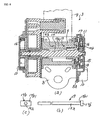
- Fig. 6(a) is an illustration schematically showing an example of the conventional seat belt retractor having the energy absorbing pin
- Fig. 6(b) is a front view of the energy absorbing pin
- Fig. 6(c) is a left side view of the energy absorbing pin.
- numeral 3 designates a seat belt retractor
- 8 designates a U-like frame
- 9 designates a spool which is rotatably supported between both side walls of the U-like frame 8 and onto which the seat belt 4 is wound
- 10 designates a deceleration sensing mechanism which senses a large vehicle deceleration generated in the event of an emergency as mentioned above and is thus actuated
- 11 designates a locking mechanism which is actuated by the deceleration sensing mechanism 10 at least to prevent the spool 9 from rotating in the belt withdrawing direction during operation
- 12 designates a torsion bar as the EA mechanism which is fitted in the center of the spool 9 with some looseness to extend in the axial direction
- 13 designates a spring mechanism which always biases the spool 9 in the belt winding direction by spring force of a spiral spring 14.
- the locking mechanism 11 comprises a pawl 15, a locking base (corresponding to the locking member of the present invention) 16 which pivotally supports the pawl 15, and a lock gear 17.
- the locking base 16 is connected to one end side (the right end side in Fig. 6(a) ) of the torsion bar 12 such that the locking base 16 can rotate together with the torsion bar 12.
- the lock gear 17 is supported by the torsion bar 12. In this case, the lock gear 17 normally rotates together with the torsion bar 12 and the locking base 16, but is stopped from rotating at least in the belt withdrawing direction by the operation of the deceleration sensing mechanism 10 in the event of an emergency.
- the left end side of the torsion bar 12 (a portion on the left end side relative to the middle in the axial direction in Fig. 6(a) ) is connected to the spool 9 such that the torsion bar 12 can rotate together with the spool 9. Therefore, though the spool 9 normally rotates together with the torsion bar 12 and the locking base 16, the torsion bar 12 rotates relative to the locking base 16 in the belt withdrawing direction as the locking base 16 is stopped from rotating in the belt withdrawing direction by the operation of the deceleration sensing mechanism 10 in the event of an emergency.
- the spool 9 is always biased in the belt winding direction via the torsion bar 12.
- a long energy absorbing pin 19 is arranged between the spool 9 and the locking base 16.
- the energy absorbing pin 19 comprises a long shaft portion 19a and a head portion 19b formed at one end of the shaft portion 19a.
- the shaft portion 19a penetrates the locking base 16 in a direction parallel to the axial direction of the spool 9 and is fitted into an axial hole 9a of the spool 9.
- the head portion 19b is formed to have a rectangular shape as seen from the side and the surface thereof around the shaft portion 19a functions as a contact surface 19b 1 which engages with the locking base 16.
- the contact surface 19b 1 is a flat surface and the shaft portion 19a projects vertically from the center of the contact surface 19b 1 .
- the seat belt 4 when the seat belt is not used, the seat belt 4 is fully wound up because of the biasing force of the spring means 13.
- the spool 9 rotates in the seat belt withdrawing direction so that the seat belt 4 is smoothly withdrawn.
- an excessively withdrawn part of the seat belt 4 is wound onto the spool 9 by the biasing force of the spring means 13 so that the seat belt 4 is fitted to the occupant to the extent that the occupant does not feel stress.
- the deceleration sensing mechanism 10 is activated by the large vehicle deceleration so as to stop the rotation of the lock gear 17 in the belt withdrawing direction. Then, the pivotal movement of the pawl 15 is controlled by a cam control hole of the lock gear 17 so that the pawl 15 engages with one of the internal teeth of the side wall 8a of the frame 8. Since the spool 9 tries to ongoingly rotate in the belt withdrawing direction while the locking base 16 is stopped from rotating in the belt withdrawing direction, the torsion bar 12 is twisted. After that, the spool 9 rotates in the belt withdrawing direction relative to the locking base 16 with twisting the torsion bar 12. By the torsional load of the torsion bar 12 during this, the load applied to the seat belt 4 is limited so as to absorb the impact exerted on the occupant.
- the load applied to the seat belt 4 can be limited also by the drawing and bending load of the energy absorbing pin 19 composed of the bending deforming force of the portion 19a 1 of the shaft portion 19a, the friction force between the spool 9 and the portion 19a 1 of the shaft portion 19a, and the bending force at the head portion 19b.
- the limited load during this is total of the torsional load of the torsion bar 12 and the drawing and bending load composed of the bending load and the friction load of the energy absorbing pin 19.
- the limited load by the energy absorbing pin 19 goes out and the limited load only by the torsional load of the torsion bar 12 exists.
- the energy absorption by the torsion bar 12 and the energy absorption by the energy absorbing pin 19 are organically combined, thereby effectively obtaining the limited load.
- the shaft portion 19a comprises a portion 19a 2 , which projects from the head portion 19b and penetrates the locking base 16, a portion 19a 3 , which is bent at a right angle from the portion 19a 2 and extends between the spool 9 and the locking base 16, and a portion 19a 1 which is bent at a right angle from the portion 19a 3 and is fitted into the axial hole 9a of the spool 9.
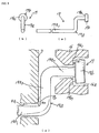
- the energy absorbing pin 19 is assembled to the spool 9 and the locking base 16 in the following manner. That is, in the normal state as shown in Fig. 9(c) , a predetermined space S 1 is set between the contact surface 19b 1 of the head portion 19b and a bottom surface 16a 1 of a concavity 16a which is formed in the locking base 16 for accommodating the head portion 19b and a predetermined space S 2 is set between a curved portion between the portion 19a 3 and the portion 19a 1 of the shaft portion 19a and an opening edge portion 9b of a drawing-side opening of the axial hole 9a. In this case, the opening edge portion 9b is rounded.
- This arrangement allows the shaft portion 19a and the head portion 19b of the energy absorbing pin 19 not to be subjected to bending load immediately after the spool 9 starts to rotate in the belt withdrawing direction relative to the locking base 16.
- the head portion 19b tilts so that the space S 1 is gone and the contact surface 19b 1 of the head portion 19b comes in contact with the bottom portion 16a 1 of the concavity 16a as shown by two dot chain lines in Fig. 9(c) .
- a limited load by the bending load of the head portion 19b is generated.
- the portion 19a 1 of the shaft portion 19a is drawn so that the space S 2 is gone and the bent portion between the portion 19a 3 and the portion 19a 1 comes in contact with the opening edge portion 9b as also shown by two dot chain lines in Fig. 9(c) . At this point, a limited load by the drawing and bending load of the shaft portion 19a is generated.
- a side of the head portion where is spaced apart from the bottom portion 16a 1 of the concavity 16a of the locking base 16 when the head portion 19b having the flat contact surface 19b 1 tilts, is significantly spaced apart from the bottom portion 16a 1 . It is therefore required to form the concavity 16a to be such deep as not to allow the head portion 19b to stick out of the concavity 16a when the head portion 19b tilts.
- the length in the axial direction of the locking base 16 (the rightward direction in Figs. 8(a) through 8(c) ) is inevitably increased.
- the positions of retractor components such as the lock gear 17 of the lock mechanism 11 and an inertia body of a webbing sensor should be shifted in the axial direction.
- the size in the axial direction of the spool 9 of the seat belt retractor 3 should be increased.
- the present invention was made under the aforementioned circumstances and an object of the present invention is to provide an inexpensive seat belt retractor which allows an energy absorbing pin to be easily assembled and allows for improved productivity even with obtaining stable limited load and to provide a seat belt apparatus employing the seat belt retractor.
- Another object of the present invention is to provide a seat belt retractor which can be made compactly even with such an arrangement that a head portion of an energy absorbing pin tilts and to provide a seat belt apparatus employing the seat belt retractor.
- a seat belt retractor comprises at least: a spool for winding up a seat belt; a locking mechanism having a locking member which rotates together with said spool in the normal state, but is prevented from rotating in a belt withdrawing direction in the event of an emergency so as generate rotational difference relative to said spool; and an energy absorbing pin which is disposed on said spool and said locking member to limit the load applied to said seat belt when the rotational difference is generated between said spool and said locking member, and is characterized in that said energy absorbing pin has a shaft portion which is fitted in a hole of said spool and a head portion which is in contact with said locking member, and a contact surface, to be in contact with said locking member, of said head portion is formed to be a curved surface.
- a seat belt retractor is characterized in that the rotation of said spool is transmitted to said locking member via a torsion bar.
- a seat belt retractor according to an embodiment of the invention is characterized in that the curved surface as the contact surface of said head portion is formed into a spherical shape.
- a seat belt retractor is characterized in that said head portion is formed into a rod-like shape, and the curved surface as the contact surface of said head portion is formed to have an arc or elliptical arc cross section in a direction perpendicular to the longitudinal direction of said head portion, and that said head portion is in contact with said locking member such that the longitudinal direction of said head portion extends in a radial direction or substantially radial direction of said locking member.
- a seat belt apparatus comprises at least: a seat belt retractor for winding up a seat belt; a tongue slidably supported by the seat belt withdrawn from said seat belt retractor; and a buckle to which said tongue can be detachably latched, wherein in the event of an emergency, said seat belt is prevented from being withdrawn by the seat belt retractor so that said seat belt apparatus restrains an occupant, and is characterized in that said seat belt retractor is a seat belt retractor as defined above.
- the contact surface of the head portion of the energy absorbing pin to be in contact with the locking member is formed in a curved surface, whereby the head portion of the energy absorbing pin is allowed to relatively easily rotate at the initial stage of the drawing action of the energy absorbing pin so that the head portion and the portion of the shaft portion adjacent to the head portion are hardly bent into a crank shape like the conventional case in which the contact surface is flat. This prevents the limited load from rapidly increasing and thus effectively prevents the limited load from overshooting at the initial stage of the EA action.
- the energy absorbing pin since the contact surface of the head portion of the energy absorbing pin is just formed to be a curved surface, the energy absorbing pin has a simple structure and can be manufactured easily. In addition, it is not necessary to form the energy absorbing pin into a crank shape so that it is only necessary to simply form the energy absorbing pin linearly. Therefore, the energy absorbing pin can further easily and cheaply manufactured. Since the energy absorbing pin has a simple structure and it is not necessary to set the predetermined spaces with a high degree of accuracy like the seat belt retractor disclosed in JP-A-2006-205821 , the energy absorbing pin can be easily assembled to the spool and the locking base and stable limited load can be obtained. This can achieve improved productivity of the seat belt retractor and easily achieve production of inexpensive seat belt retractors.
- the seat belt retractor of the present invention can sufficiently and flexibly meet the need for the vehicle cabin space as mentioned above.
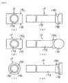
- Fig. 1 is an illustration schematically showing a part of a seat belt retractor as an embodiment according to the present invention.
- the same components as those in the aforementioned conventional one are marked with the same numerals so that detailed description thereof will be omitted.
- an energy absorbing pin 19 penetrates a locking base 16 and a portion 19a 1 of a shaft portion 19a is fitted in an axial hole 9a of a spool 9 similarly to the aforementioned conventional example shown in Figs. 6(a)-6(c) .
- the shaft portion 19a is formed linearly and projects orthogonally from a head portion 19b.
- the head portion 19b is formed to have a rectangular rod-like shape as seen from a side and has a contact surface 19b 1 of which cross section (a section extending in a direction perpendicular to the longitudinal direction of the head portion 19b) is formed to be a curved surface such as an arc surface or an elliptical arc surface.
- the rectangular head portion 19b has a flat surface on the side opposite to the contact surface 19b 1 .
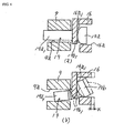
- an edge 16b of a concavity 16a of the locking base 16 on the ⁇ side in the belt withdrawing direction extends linearly in substantially a radial direction of the locking base 16 (a direction substantially perpendicular to the rotational direction of the locking base 16).
- a linear side edge 19b 2 of the head portion 19b of the energy absorbing pin 19 on the ⁇ side in the belt withdrawing direction is in plane contact with the edge 16b, on the ⁇ side in the belt withdrawing direction, of the concavity 16a of the locking base 16.
- the curved contact surface 19b 1 is partially in contact with the bottom surface 16a 1 of the concavity 16a of the locking base 16.
- the edge 16b of the concavity 16a of the locking base 16 may linearly extend in a radial direction of the locking base 16 (in a direction perpendicular to the rotational direction of the locking base 16).
- the side edge 19b 2 of the head portion 19b of the energy absorbing pin 19 is in plane contact with the edge 16b of the concavity 16a of the locking base 16 in the radial direction.
- the energy absorbing pin 19 in the seat belt retractor 3 As the spool 9 rotates in the belt withdrawing direction relative to the locking base 16 in the event of an emergency from the normal state shown in Fig. 4(a) , the energy absorbing pin 19 is drawn out. During this, the head portion 19b is subjected to bending force in the rotational direction of the locking base 16 about an axis in the radial direction of the locking base 16. Since the contact surface 19b 1 of the energy absorbing pin 19 is a curved surface so that the head portion 19b is easy to tilt (rotate), the head portion 19b easy tilts about an axis in the radial direction of the locking base 16 as shown in Fig.
- This arrangement allows the length of the locking base 16 in the axial direction to be shorter, as shown by solid lines in Fig. 4(b) , than that of the locking base 16 in case of using the conventional energy absorbing pin 19 having the flat contact surface 19b 1 as shown by two dot chain lines in Fig. 4(b) . This can achieve the seat belt retractor 3 having a smaller size.
- the contact surface 19b 1 to be contact with the locking base 16, of the head portion 19b of the energy absorbing pin 19 is formed in a curved surface, whereby the head portion 19b of the energy absorbing pin 19 is allowed to relatively easily rotate at the initial stage of the drawing action of the energy absorbing pin 19 so that the head portion 19b and the portion 19a 2 of the shaft portion 19a adjacent to the head portion 19b are hardly bent into a crank shape like the conventional case in which the contact surface 19b 1 is flat. This prevents the limited load from rapidly increasing and thus effectively prevents the limited load from overshooting at the initial stage of the EA action.
- the energy absorbing pin 19 of this embodiment has a simple structure and can be manufactured easily. In addition, it is not necessary to form the energy absorbing pin 19 into a crank shape so that it is only necessary to simply form the energy absorbing pin 19 linearly. Therefore, the energy absorbing pin 19 can further easily and cheaply manufactured. Since the energy absorbing pin 19 has a simple structure and it is not necessary to set the predetermined spaces S 1 and S 2 with a high degree of accuracy like the seat belt retractor disclosed in Patent document 1, the energy absorbing pin 19 can be easily assembled to the spool 9 and the locking base 16 and stable limited load can be obtained. This can achieve improved productivity of the seat belt retractor 3 and easily achieve production of inexpensive seat belt retractor 3.
- the seat belt retractor 3 of this embodiment can sufficiently and flexibly meet the need for the vehicle cabin space as mentioned above.
- the seat belt retractor 3 of this embodiment can be employed in any seat belt apparatus 1 as long as the seat belt apparatus 1 employs the seat belt retractor 3, as well as the seat belt apparatus 1 shown in Fig. 5 , for example. Accordingly, an occupant of the vehicle can be efficiently restrained by the seat belt apparatus 1 in the event of an emergency.
- Figs. 2(c) through 2(f) are illustrations of energy absorbing pins of other examples according to the embodiment of the present invention, respectively.
- An energy absorbing pin 19 of an example shown in Figs. 2(c) and 2(d) has a head portion 19b which is composed of a cylindrical member.
- the cylindrical member is bonded orthogonally to the shaft portion 19a. That is, the contact surface 19b 1 of the head portion 19b is an arc curved surface.
- An energy absorbing pin 19 of an example shown in Figs. 2(e) and 2(f) has a head portion 19b having a circular shape as seen from a side which is coaxial to a shaft portion 19a thereof.
- the contact surface 19b 1 of the head portion 19b is a spherical curved surface. In case of the contact surface composed of the spherical curved surface, the head portion 19b is directionless relative to the locking base in the state that the energy absorbing pin 19 is assembled.
- the seat belt retractor according to the present invention is not limited to the aforementioned embodiments and can be applied to any seat belt retractor employing an energy absorbing pin 19 which is disposed between a spool 9 and a locking base 16 to absorb inertial energy of an occupant in the event of an emergency, within a scope of the claims of the present invention.
- the seat belt retractor of the present invention is suitably used as a seat belt retractor which is used in a seat belt apparatus installed in a vehicle such as an automobile and which prevents a seat belt from being withdrawn while absorbing inertial energy of an occupant by limiting the load applied to the seat belt with an energy absorbing member in the event of an emergency such as a vehicle collision.
Landscapes
- Engineering & Computer Science (AREA)
- Mechanical Engineering (AREA)
- Automotive Seat Belt Assembly (AREA)
- Seats For Vehicles (AREA)
Applications Claiming Priority (1)
| Application Number | Priority Date | Filing Date | Title |
|---|---|---|---|
| JP2007277604A JP4956371B2 (ja) | 2007-10-25 | 2007-10-25 | シートベルトリトラクタおよびこれを備えているシートベルト装置 |
Publications (3)
| Publication Number | Publication Date |
|---|---|
| EP2052920A2 EP2052920A2 (en) | 2009-04-29 |
| EP2052920A3 EP2052920A3 (en) | 2010-05-05 |
| EP2052920B1 true EP2052920B1 (en) | 2011-07-06 |
Family
ID=40148622
Family Applications (1)
| Application Number | Title | Priority Date | Filing Date |
|---|---|---|---|
| EP08016151A Expired - Fee Related EP2052920B1 (en) | 2007-10-25 | 2008-09-12 | Seat belt retractor and seat belt apparatus having the same |
Country Status (4)
| Country | Link |
|---|---|
| US (1) | US20090108117A1 (ja) |
| EP (1) | EP2052920B1 (ja) |
| JP (1) | JP4956371B2 (ja) |
| CN (1) | CN101417642B (ja) |
Families Citing this family (3)
| Publication number | Priority date | Publication date | Assignee | Title |
|---|---|---|---|---|
| EP2743142B1 (en) * | 2012-12-12 | 2020-03-25 | Volvo Car Corporation | Method for retracting a seat belt |
| EP3018010B1 (en) * | 2014-11-06 | 2018-01-10 | Volvo Car Corporation | Method for controlling a time of activation of a reversible restraint system in a vehicle |
| US10377340B2 (en) | 2017-03-16 | 2019-08-13 | Ford Global Technologies, Llc | Restraint system |
Family Cites Families (24)
| Publication number | Priority date | Publication date | Assignee | Title |
|---|---|---|---|---|
| GB1268055A (en) * | 1968-12-05 | 1972-03-22 | Antonio Brandestini | Improvements in or relating to methods of winding tensioning wires around containers to be pre-stressed |
| JPS54153425A (en) * | 1978-05-23 | 1979-12-03 | Nippon Soken Inc | Seat belt tightening apparatus |
| US4674801A (en) * | 1985-02-06 | 1987-06-23 | Allied Corporation | Energy absorber having a limited stroke |
| DE3534048A1 (de) * | 1985-09-24 | 1987-04-16 | Trw Repa Gmbh | Sicherheitsgurtaufroller mit rueckstrammeinrichtung |
| ES2014639A6 (es) * | 1989-06-05 | 1990-07-16 | Pujol & Tarago | Dispositivo de enganche para cables metalicos. |
| US5836061A (en) * | 1997-07-12 | 1998-11-17 | Honda Giken Kogyo Kabushiki Kaisha | Cable end anchoring nipple and methods of constructing and utilizing same |
| DE19511457A1 (de) * | 1995-03-29 | 1996-10-02 | Trw Repa Gmbh | Kraftbegrenzung in einem Insassen-Rückhaltesystem |
| DE19528115A1 (de) * | 1995-08-01 | 1997-02-06 | Autoliv Dev | Gurtaufroller mit in einem Drehweg begrenzten Kraftbegrenzer |
| JP3842622B2 (ja) * | 2001-11-13 | 2006-11-08 | 株式会社東海理化電機製作所 | ウエビング巻取装置 |
| JP4662214B2 (ja) | 1999-08-18 | 2011-03-30 | タカタ株式会社 | シートベルトリトラクタ |
| JP2001301563A (ja) * | 2000-04-24 | 2001-10-31 | Tokai Rika Co Ltd | ウエビング巻取装置 |
| JP2001301569A (ja) * | 2000-04-24 | 2001-10-31 | Tokai Rika Co Ltd | ウェビング巻取装置及び車両 |
| US20020092943A1 (en) * | 2000-07-14 | 2002-07-18 | Breed Automotive Technology, Inc. | Energy absorbing seat belt retractor |
| JP3754283B2 (ja) * | 2000-08-15 | 2006-03-08 | 株式会社東海理化電機製作所 | ウエビング巻取装置 |
| DE10164638A1 (de) * | 2000-12-28 | 2002-07-11 | Takata Europa Vehicle Safety T | Gurtkraftbegrenzer |
| JP4559666B2 (ja) * | 2001-07-11 | 2010-10-13 | 株式会社東海理化電機製作所 | ウエビング巻取装置 |
| JP3984024B2 (ja) * | 2001-11-02 | 2007-09-26 | 株式会社東海理化電機製作所 | ウエビング巻取装置 |
| GB2387576B (en) * | 2002-04-16 | 2004-04-14 | Breed Automotive Tech | Retractor |
| JP2005029014A (ja) * | 2003-07-14 | 2005-02-03 | Takata Corp | シートベルトリトラクタ |
| EP1619091B1 (en) * | 2004-07-20 | 2007-10-03 | Key Safety Systems, Inc. | Retractor |
| JP2006205821A (ja) * | 2005-01-26 | 2006-08-10 | Tokai Rika Co Ltd | ウエビング巻取装置 |
| JP2006298247A (ja) * | 2005-04-22 | 2006-11-02 | Takata Corp | シートベルトリトラクタ及びシートベルト装置 |
| JP4908927B2 (ja) * | 2005-08-22 | 2012-04-04 | 株式会社東海理化電機製作所 | ウエビング巻取装置 |
| DE102005032012A1 (de) * | 2005-07-01 | 2007-01-11 | Takata-Petri (Ulm) Gmbh | Gurtaufroller |
-
2007
- 2007-10-25 JP JP2007277604A patent/JP4956371B2/ja not_active Expired - Fee Related
-
2008
- 2008-09-04 US US12/230,753 patent/US20090108117A1/en not_active Abandoned
- 2008-09-12 EP EP08016151A patent/EP2052920B1/en not_active Expired - Fee Related
- 2008-10-27 CN CN2008101690988A patent/CN101417642B/zh not_active Expired - Fee Related
Also Published As
| Publication number | Publication date |
|---|---|
| JP4956371B2 (ja) | 2012-06-20 |
| EP2052920A2 (en) | 2009-04-29 |
| JP2009101957A (ja) | 2009-05-14 |
| CN101417642A (zh) | 2009-04-29 |
| EP2052920A3 (en) | 2010-05-05 |
| US20090108117A1 (en) | 2009-04-30 |
| CN101417642B (zh) | 2012-12-26 |
Similar Documents
| Publication | Publication Date | Title |
|---|---|---|
| EP1918165B1 (en) | Seat belt retractor and seat belt apparatus comprising the same | |
| EP1283137B1 (en) | Pretensioner | |
| US9283928B2 (en) | Load limiter | |
| EP2186692A1 (en) | Seat belt retractor and seat belt apparatus having the same | |
| JP6827043B2 (ja) | ウェビング巻取装置 | |
| US20200298793A1 (en) | Pretensioner, retractor, and seat belt device | |
| EP2052920B1 (en) | Seat belt retractor and seat belt apparatus having the same | |
| EP1975016B1 (en) | Seat belt retractor and seat belt apparatus having the same | |
| US9212024B2 (en) | Webbing retractor | |
| JP5226541B2 (ja) | ウエビング巻取装置 | |
| US20130233958A1 (en) | Webbing retractor | |
| EP1975017B1 (en) | Seat belt retractor and seat belt apparatus having the same | |
| JP5160373B2 (ja) | シートベルトリトラクタおよびこれを備えているシートベルト装置 | |
| JP5155135B2 (ja) | ウエビング巻取装置 | |
| JP6694765B2 (ja) | ウェビング巻取装置 | |
| JP2020044969A (ja) | プリテンショナ、リトラクタ及びシートベルト装置 | |
| JP7324651B2 (ja) | プリテンショナ、リトラクタ及びシートベルト装置 | |
| JP7354015B2 (ja) | プリテンショナ、リトラクタ及びシートベルト装置 | |
| JP7232700B2 (ja) | プリテンショナ、リトラクタ及びシートベルト装置 | |
| JP2009113503A (ja) | シートベルトリトラクタおよびこれを備えているシートベルト装置 | |
| JP4153929B2 (ja) | シートベルトリトラクタ | |
| KR101370485B1 (ko) | 웨빙 권취 장치 | |
| JP2010000828A (ja) | ウエビング巻取装置 | |
| JP2022134558A (ja) | プリテンショナ、リトラクタ及びシートベルト装置 | |
| JP2006213102A (ja) | ウエビング巻取装置 |
Legal Events
| Date | Code | Title | Description |
|---|---|---|---|
| PUAI | Public reference made under article 153(3) epc to a published international application that has entered the european phase |
Free format text: ORIGINAL CODE: 0009012 |
|
| AK | Designated contracting states |
Kind code of ref document: A2 Designated state(s): AT BE BG CH CY CZ DE DK EE ES FI FR GB GR HR HU IE IS IT LI LT LU LV MC MT NL NO PL PT RO SE SI SK TR |
|
| AX | Request for extension of the european patent |
Extension state: AL BA MK RS |
|
| PUAL | Search report despatched |
Free format text: ORIGINAL CODE: 0009013 |
|
| AK | Designated contracting states |
Kind code of ref document: A3 Designated state(s): AT BE BG CH CY CZ DE DK EE ES FI FR GB GR HR HU IE IS IT LI LT LU LV MC MT NL NO PL PT RO SE SI SK TR |
|
| AX | Request for extension of the european patent |
Extension state: AL BA MK RS |
|
| 17P | Request for examination filed |
Effective date: 20101020 |
|
| AKX | Designation fees paid |
Designated state(s): DE GB |
|
| GRAP | Despatch of communication of intention to grant a patent |
Free format text: ORIGINAL CODE: EPIDOSNIGR1 |
|
| GRAS | Grant fee paid |
Free format text: ORIGINAL CODE: EPIDOSNIGR3 |
|
| GRAA | (expected) grant |
Free format text: ORIGINAL CODE: 0009210 |
|
| AK | Designated contracting states |
Kind code of ref document: B1 Designated state(s): DE GB |
|
| REG | Reference to a national code |
Ref country code: GB Ref legal event code: FG4D |
|
| REG | Reference to a national code |
Ref country code: DE Ref legal event code: R096 Ref document number: 602008008042 Country of ref document: DE Effective date: 20110825 |
|
| PLBE | No opposition filed within time limit |
Free format text: ORIGINAL CODE: 0009261 |
|
| STAA | Information on the status of an ep patent application or granted ep patent |
Free format text: STATUS: NO OPPOSITION FILED WITHIN TIME LIMIT |
|
| 26N | No opposition filed |
Effective date: 20120411 |
|
| REG | Reference to a national code |
Ref country code: DE Ref legal event code: R097 Ref document number: 602008008042 Country of ref document: DE Effective date: 20120411 |
|
| PGFP | Annual fee paid to national office [announced via postgrant information from national office to epo] |
Ref country code: GB Payment date: 20130911 Year of fee payment: 6 |
|
| GBPC | Gb: european patent ceased through non-payment of renewal fee |
Effective date: 20140912 |
|
| PG25 | Lapsed in a contracting state [announced via postgrant information from national office to epo] |
Ref country code: GB Free format text: LAPSE BECAUSE OF NON-PAYMENT OF DUE FEES Effective date: 20140912 |
|
| REG | Reference to a national code |
Ref country code: DE Ref legal event code: R082 Ref document number: 602008008042 Country of ref document: DE Representative=s name: KRAUS & WEISERT PATENTANWAELTE PARTGMBB, DE Ref country code: DE Ref legal event code: R081 Ref document number: 602008008042 Country of ref document: DE Owner name: JOYSON SAFETY SYSTEMS JAPAN K.K., JP Free format text: FORMER OWNER: TAKATA CORP., TOKIO/TOKYO, JP |
|
| PGFP | Annual fee paid to national office [announced via postgrant information from national office to epo] |
Ref country code: DE Payment date: 20180920 Year of fee payment: 11 |
|
| REG | Reference to a national code |
Ref country code: DE Ref legal event code: R119 Ref document number: 602008008042 Country of ref document: DE |
|
| PG25 | Lapsed in a contracting state [announced via postgrant information from national office to epo] |
Ref country code: DE Free format text: LAPSE BECAUSE OF NON-PAYMENT OF DUE FEES Effective date: 20200401 |