EP2048054B1 - Dispositif et procédé de détermination de raté d'allumage dans un moteur à combustion interne - Google Patents
Dispositif et procédé de détermination de raté d'allumage dans un moteur à combustion interne Download PDFInfo
- Publication number
- EP2048054B1 EP2048054B1 EP07767768.0A EP07767768A EP2048054B1 EP 2048054 B1 EP2048054 B1 EP 2048054B1 EP 07767768 A EP07767768 A EP 07767768A EP 2048054 B1 EP2048054 B1 EP 2048054B1
- Authority
- EP
- European Patent Office
- Prior art keywords
- misfire
- internal combustion
- combustion engine
- engine
- detection
- Prior art date
- Legal status (The legal status is an assumption and is not a legal conclusion. Google has not performed a legal analysis and makes no representation as to the accuracy of the status listed.)
- Active
Links
Images


Classifications
-
- B—PERFORMING OPERATIONS; TRANSPORTING
- B60—VEHICLES IN GENERAL
- B60W—CONJOINT CONTROL OF VEHICLE SUB-UNITS OF DIFFERENT TYPE OR DIFFERENT FUNCTION; CONTROL SYSTEMS SPECIALLY ADAPTED FOR HYBRID VEHICLES; ROAD VEHICLE DRIVE CONTROL SYSTEMS FOR PURPOSES NOT RELATED TO THE CONTROL OF A PARTICULAR SUB-UNIT
- B60W20/00—Control systems specially adapted for hybrid vehicles
- B60W20/50—Control strategies for responding to system failures, e.g. for fault diagnosis, failsafe operation or limp mode
-
- B—PERFORMING OPERATIONS; TRANSPORTING
- B60—VEHICLES IN GENERAL
- B60K—ARRANGEMENT OR MOUNTING OF PROPULSION UNITS OR OF TRANSMISSIONS IN VEHICLES; ARRANGEMENT OR MOUNTING OF PLURAL DIVERSE PRIME-MOVERS IN VEHICLES; AUXILIARY DRIVES FOR VEHICLES; INSTRUMENTATION OR DASHBOARDS FOR VEHICLES; ARRANGEMENTS IN CONNECTION WITH COOLING, AIR INTAKE, GAS EXHAUST OR FUEL SUPPLY OF PROPULSION UNITS IN VEHICLES
- B60K6/00—Arrangement or mounting of plural diverse prime-movers for mutual or common propulsion, e.g. hybrid propulsion systems comprising electric motors and internal combustion engines ; Control systems therefor, i.e. systems controlling two or more prime movers, or controlling one of these prime movers and any of the transmission, drive or drive units Informative references: mechanical gearings with secondary electric drive F16H3/72; arrangements for handling mechanical energy structurally associated with the dynamo-electric machine H02K7/00; machines comprising structurally interrelated motor and generator parts H02K51/00; dynamo-electric machines not otherwise provided for in H02K see H02K99/00
- B60K6/20—Arrangement or mounting of plural diverse prime-movers for mutual or common propulsion, e.g. hybrid propulsion systems comprising electric motors and internal combustion engines ; Control systems therefor, i.e. systems controlling two or more prime movers, or controlling one of these prime movers and any of the transmission, drive or drive units Informative references: mechanical gearings with secondary electric drive F16H3/72; arrangements for handling mechanical energy structurally associated with the dynamo-electric machine H02K7/00; machines comprising structurally interrelated motor and generator parts H02K51/00; dynamo-electric machines not otherwise provided for in H02K see H02K99/00 the prime-movers consisting of electric motors and internal combustion engines, e.g. HEVs
- B60K6/22—Arrangement or mounting of plural diverse prime-movers for mutual or common propulsion, e.g. hybrid propulsion systems comprising electric motors and internal combustion engines ; Control systems therefor, i.e. systems controlling two or more prime movers, or controlling one of these prime movers and any of the transmission, drive or drive units Informative references: mechanical gearings with secondary electric drive F16H3/72; arrangements for handling mechanical energy structurally associated with the dynamo-electric machine H02K7/00; machines comprising structurally interrelated motor and generator parts H02K51/00; dynamo-electric machines not otherwise provided for in H02K see H02K99/00 the prime-movers consisting of electric motors and internal combustion engines, e.g. HEVs characterised by apparatus, components or means specially adapted for HEVs
- B60K6/24—Arrangement or mounting of plural diverse prime-movers for mutual or common propulsion, e.g. hybrid propulsion systems comprising electric motors and internal combustion engines ; Control systems therefor, i.e. systems controlling two or more prime movers, or controlling one of these prime movers and any of the transmission, drive or drive units Informative references: mechanical gearings with secondary electric drive F16H3/72; arrangements for handling mechanical energy structurally associated with the dynamo-electric machine H02K7/00; machines comprising structurally interrelated motor and generator parts H02K51/00; dynamo-electric machines not otherwise provided for in H02K see H02K99/00 the prime-movers consisting of electric motors and internal combustion engines, e.g. HEVs characterised by apparatus, components or means specially adapted for HEVs characterised by the combustion engines
-
- B—PERFORMING OPERATIONS; TRANSPORTING
- B60—VEHICLES IN GENERAL
- B60K—ARRANGEMENT OR MOUNTING OF PROPULSION UNITS OR OF TRANSMISSIONS IN VEHICLES; ARRANGEMENT OR MOUNTING OF PLURAL DIVERSE PRIME-MOVERS IN VEHICLES; AUXILIARY DRIVES FOR VEHICLES; INSTRUMENTATION OR DASHBOARDS FOR VEHICLES; ARRANGEMENTS IN CONNECTION WITH COOLING, AIR INTAKE, GAS EXHAUST OR FUEL SUPPLY OF PROPULSION UNITS IN VEHICLES
- B60K6/00—Arrangement or mounting of plural diverse prime-movers for mutual or common propulsion, e.g. hybrid propulsion systems comprising electric motors and internal combustion engines ; Control systems therefor, i.e. systems controlling two or more prime movers, or controlling one of these prime movers and any of the transmission, drive or drive units Informative references: mechanical gearings with secondary electric drive F16H3/72; arrangements for handling mechanical energy structurally associated with the dynamo-electric machine H02K7/00; machines comprising structurally interrelated motor and generator parts H02K51/00; dynamo-electric machines not otherwise provided for in H02K see H02K99/00
- B60K6/20—Arrangement or mounting of plural diverse prime-movers for mutual or common propulsion, e.g. hybrid propulsion systems comprising electric motors and internal combustion engines ; Control systems therefor, i.e. systems controlling two or more prime movers, or controlling one of these prime movers and any of the transmission, drive or drive units Informative references: mechanical gearings with secondary electric drive F16H3/72; arrangements for handling mechanical energy structurally associated with the dynamo-electric machine H02K7/00; machines comprising structurally interrelated motor and generator parts H02K51/00; dynamo-electric machines not otherwise provided for in H02K see H02K99/00 the prime-movers consisting of electric motors and internal combustion engines, e.g. HEVs
- B60K6/22—Arrangement or mounting of plural diverse prime-movers for mutual or common propulsion, e.g. hybrid propulsion systems comprising electric motors and internal combustion engines ; Control systems therefor, i.e. systems controlling two or more prime movers, or controlling one of these prime movers and any of the transmission, drive or drive units Informative references: mechanical gearings with secondary electric drive F16H3/72; arrangements for handling mechanical energy structurally associated with the dynamo-electric machine H02K7/00; machines comprising structurally interrelated motor and generator parts H02K51/00; dynamo-electric machines not otherwise provided for in H02K see H02K99/00 the prime-movers consisting of electric motors and internal combustion engines, e.g. HEVs characterised by apparatus, components or means specially adapted for HEVs
- B60K6/26—Arrangement or mounting of plural diverse prime-movers for mutual or common propulsion, e.g. hybrid propulsion systems comprising electric motors and internal combustion engines ; Control systems therefor, i.e. systems controlling two or more prime movers, or controlling one of these prime movers and any of the transmission, drive or drive units Informative references: mechanical gearings with secondary electric drive F16H3/72; arrangements for handling mechanical energy structurally associated with the dynamo-electric machine H02K7/00; machines comprising structurally interrelated motor and generator parts H02K51/00; dynamo-electric machines not otherwise provided for in H02K see H02K99/00 the prime-movers consisting of electric motors and internal combustion engines, e.g. HEVs characterised by apparatus, components or means specially adapted for HEVs characterised by the motors or the generators
-
- B—PERFORMING OPERATIONS; TRANSPORTING
- B60—VEHICLES IN GENERAL
- B60K—ARRANGEMENT OR MOUNTING OF PROPULSION UNITS OR OF TRANSMISSIONS IN VEHICLES; ARRANGEMENT OR MOUNTING OF PLURAL DIVERSE PRIME-MOVERS IN VEHICLES; AUXILIARY DRIVES FOR VEHICLES; INSTRUMENTATION OR DASHBOARDS FOR VEHICLES; ARRANGEMENTS IN CONNECTION WITH COOLING, AIR INTAKE, GAS EXHAUST OR FUEL SUPPLY OF PROPULSION UNITS IN VEHICLES
- B60K6/00—Arrangement or mounting of plural diverse prime-movers for mutual or common propulsion, e.g. hybrid propulsion systems comprising electric motors and internal combustion engines ; Control systems therefor, i.e. systems controlling two or more prime movers, or controlling one of these prime movers and any of the transmission, drive or drive units Informative references: mechanical gearings with secondary electric drive F16H3/72; arrangements for handling mechanical energy structurally associated with the dynamo-electric machine H02K7/00; machines comprising structurally interrelated motor and generator parts H02K51/00; dynamo-electric machines not otherwise provided for in H02K see H02K99/00
- B60K6/20—Arrangement or mounting of plural diverse prime-movers for mutual or common propulsion, e.g. hybrid propulsion systems comprising electric motors and internal combustion engines ; Control systems therefor, i.e. systems controlling two or more prime movers, or controlling one of these prime movers and any of the transmission, drive or drive units Informative references: mechanical gearings with secondary electric drive F16H3/72; arrangements for handling mechanical energy structurally associated with the dynamo-electric machine H02K7/00; machines comprising structurally interrelated motor and generator parts H02K51/00; dynamo-electric machines not otherwise provided for in H02K see H02K99/00 the prime-movers consisting of electric motors and internal combustion engines, e.g. HEVs
- B60K6/22—Arrangement or mounting of plural diverse prime-movers for mutual or common propulsion, e.g. hybrid propulsion systems comprising electric motors and internal combustion engines ; Control systems therefor, i.e. systems controlling two or more prime movers, or controlling one of these prime movers and any of the transmission, drive or drive units Informative references: mechanical gearings with secondary electric drive F16H3/72; arrangements for handling mechanical energy structurally associated with the dynamo-electric machine H02K7/00; machines comprising structurally interrelated motor and generator parts H02K51/00; dynamo-electric machines not otherwise provided for in H02K see H02K99/00 the prime-movers consisting of electric motors and internal combustion engines, e.g. HEVs characterised by apparatus, components or means specially adapted for HEVs
- B60K6/36—Arrangement or mounting of plural diverse prime-movers for mutual or common propulsion, e.g. hybrid propulsion systems comprising electric motors and internal combustion engines ; Control systems therefor, i.e. systems controlling two or more prime movers, or controlling one of these prime movers and any of the transmission, drive or drive units Informative references: mechanical gearings with secondary electric drive F16H3/72; arrangements for handling mechanical energy structurally associated with the dynamo-electric machine H02K7/00; machines comprising structurally interrelated motor and generator parts H02K51/00; dynamo-electric machines not otherwise provided for in H02K see H02K99/00 the prime-movers consisting of electric motors and internal combustion engines, e.g. HEVs characterised by apparatus, components or means specially adapted for HEVs characterised by the transmission gearings
- B60K6/365—Arrangement or mounting of plural diverse prime-movers for mutual or common propulsion, e.g. hybrid propulsion systems comprising electric motors and internal combustion engines ; Control systems therefor, i.e. systems controlling two or more prime movers, or controlling one of these prime movers and any of the transmission, drive or drive units Informative references: mechanical gearings with secondary electric drive F16H3/72; arrangements for handling mechanical energy structurally associated with the dynamo-electric machine H02K7/00; machines comprising structurally interrelated motor and generator parts H02K51/00; dynamo-electric machines not otherwise provided for in H02K see H02K99/00 the prime-movers consisting of electric motors and internal combustion engines, e.g. HEVs characterised by apparatus, components or means specially adapted for HEVs characterised by the transmission gearings with the gears having orbital motion
-
- B—PERFORMING OPERATIONS; TRANSPORTING
- B60—VEHICLES IN GENERAL
- B60K—ARRANGEMENT OR MOUNTING OF PROPULSION UNITS OR OF TRANSMISSIONS IN VEHICLES; ARRANGEMENT OR MOUNTING OF PLURAL DIVERSE PRIME-MOVERS IN VEHICLES; AUXILIARY DRIVES FOR VEHICLES; INSTRUMENTATION OR DASHBOARDS FOR VEHICLES; ARRANGEMENTS IN CONNECTION WITH COOLING, AIR INTAKE, GAS EXHAUST OR FUEL SUPPLY OF PROPULSION UNITS IN VEHICLES
- B60K6/00—Arrangement or mounting of plural diverse prime-movers for mutual or common propulsion, e.g. hybrid propulsion systems comprising electric motors and internal combustion engines ; Control systems therefor, i.e. systems controlling two or more prime movers, or controlling one of these prime movers and any of the transmission, drive or drive units Informative references: mechanical gearings with secondary electric drive F16H3/72; arrangements for handling mechanical energy structurally associated with the dynamo-electric machine H02K7/00; machines comprising structurally interrelated motor and generator parts H02K51/00; dynamo-electric machines not otherwise provided for in H02K see H02K99/00
- B60K6/20—Arrangement or mounting of plural diverse prime-movers for mutual or common propulsion, e.g. hybrid propulsion systems comprising electric motors and internal combustion engines ; Control systems therefor, i.e. systems controlling two or more prime movers, or controlling one of these prime movers and any of the transmission, drive or drive units Informative references: mechanical gearings with secondary electric drive F16H3/72; arrangements for handling mechanical energy structurally associated with the dynamo-electric machine H02K7/00; machines comprising structurally interrelated motor and generator parts H02K51/00; dynamo-electric machines not otherwise provided for in H02K see H02K99/00 the prime-movers consisting of electric motors and internal combustion engines, e.g. HEVs
- B60K6/22—Arrangement or mounting of plural diverse prime-movers for mutual or common propulsion, e.g. hybrid propulsion systems comprising electric motors and internal combustion engines ; Control systems therefor, i.e. systems controlling two or more prime movers, or controlling one of these prime movers and any of the transmission, drive or drive units Informative references: mechanical gearings with secondary electric drive F16H3/72; arrangements for handling mechanical energy structurally associated with the dynamo-electric machine H02K7/00; machines comprising structurally interrelated motor and generator parts H02K51/00; dynamo-electric machines not otherwise provided for in H02K see H02K99/00 the prime-movers consisting of electric motors and internal combustion engines, e.g. HEVs characterised by apparatus, components or means specially adapted for HEVs
- B60K6/40—Arrangement or mounting of plural diverse prime-movers for mutual or common propulsion, e.g. hybrid propulsion systems comprising electric motors and internal combustion engines ; Control systems therefor, i.e. systems controlling two or more prime movers, or controlling one of these prime movers and any of the transmission, drive or drive units Informative references: mechanical gearings with secondary electric drive F16H3/72; arrangements for handling mechanical energy structurally associated with the dynamo-electric machine H02K7/00; machines comprising structurally interrelated motor and generator parts H02K51/00; dynamo-electric machines not otherwise provided for in H02K see H02K99/00 the prime-movers consisting of electric motors and internal combustion engines, e.g. HEVs characterised by apparatus, components or means specially adapted for HEVs characterised by the assembly or relative disposition of components
-
- B—PERFORMING OPERATIONS; TRANSPORTING
- B60—VEHICLES IN GENERAL
- B60K—ARRANGEMENT OR MOUNTING OF PROPULSION UNITS OR OF TRANSMISSIONS IN VEHICLES; ARRANGEMENT OR MOUNTING OF PLURAL DIVERSE PRIME-MOVERS IN VEHICLES; AUXILIARY DRIVES FOR VEHICLES; INSTRUMENTATION OR DASHBOARDS FOR VEHICLES; ARRANGEMENTS IN CONNECTION WITH COOLING, AIR INTAKE, GAS EXHAUST OR FUEL SUPPLY OF PROPULSION UNITS IN VEHICLES
- B60K6/00—Arrangement or mounting of plural diverse prime-movers for mutual or common propulsion, e.g. hybrid propulsion systems comprising electric motors and internal combustion engines ; Control systems therefor, i.e. systems controlling two or more prime movers, or controlling one of these prime movers and any of the transmission, drive or drive units Informative references: mechanical gearings with secondary electric drive F16H3/72; arrangements for handling mechanical energy structurally associated with the dynamo-electric machine H02K7/00; machines comprising structurally interrelated motor and generator parts H02K51/00; dynamo-electric machines not otherwise provided for in H02K see H02K99/00
- B60K6/20—Arrangement or mounting of plural diverse prime-movers for mutual or common propulsion, e.g. hybrid propulsion systems comprising electric motors and internal combustion engines ; Control systems therefor, i.e. systems controlling two or more prime movers, or controlling one of these prime movers and any of the transmission, drive or drive units Informative references: mechanical gearings with secondary electric drive F16H3/72; arrangements for handling mechanical energy structurally associated with the dynamo-electric machine H02K7/00; machines comprising structurally interrelated motor and generator parts H02K51/00; dynamo-electric machines not otherwise provided for in H02K see H02K99/00 the prime-movers consisting of electric motors and internal combustion engines, e.g. HEVs
- B60K6/42—Arrangement or mounting of plural diverse prime-movers for mutual or common propulsion, e.g. hybrid propulsion systems comprising electric motors and internal combustion engines ; Control systems therefor, i.e. systems controlling two or more prime movers, or controlling one of these prime movers and any of the transmission, drive or drive units Informative references: mechanical gearings with secondary electric drive F16H3/72; arrangements for handling mechanical energy structurally associated with the dynamo-electric machine H02K7/00; machines comprising structurally interrelated motor and generator parts H02K51/00; dynamo-electric machines not otherwise provided for in H02K see H02K99/00 the prime-movers consisting of electric motors and internal combustion engines, e.g. HEVs characterised by the architecture of the hybrid electric vehicle
- B60K6/44—Series-parallel type
- B60K6/445—Differential gearing distribution type
-
- B—PERFORMING OPERATIONS; TRANSPORTING
- B60—VEHICLES IN GENERAL
- B60K—ARRANGEMENT OR MOUNTING OF PROPULSION UNITS OR OF TRANSMISSIONS IN VEHICLES; ARRANGEMENT OR MOUNTING OF PLURAL DIVERSE PRIME-MOVERS IN VEHICLES; AUXILIARY DRIVES FOR VEHICLES; INSTRUMENTATION OR DASHBOARDS FOR VEHICLES; ARRANGEMENTS IN CONNECTION WITH COOLING, AIR INTAKE, GAS EXHAUST OR FUEL SUPPLY OF PROPULSION UNITS IN VEHICLES
- B60K6/00—Arrangement or mounting of plural diverse prime-movers for mutual or common propulsion, e.g. hybrid propulsion systems comprising electric motors and internal combustion engines ; Control systems therefor, i.e. systems controlling two or more prime movers, or controlling one of these prime movers and any of the transmission, drive or drive units Informative references: mechanical gearings with secondary electric drive F16H3/72; arrangements for handling mechanical energy structurally associated with the dynamo-electric machine H02K7/00; machines comprising structurally interrelated motor and generator parts H02K51/00; dynamo-electric machines not otherwise provided for in H02K see H02K99/00
- B60K6/20—Arrangement or mounting of plural diverse prime-movers for mutual or common propulsion, e.g. hybrid propulsion systems comprising electric motors and internal combustion engines ; Control systems therefor, i.e. systems controlling two or more prime movers, or controlling one of these prime movers and any of the transmission, drive or drive units Informative references: mechanical gearings with secondary electric drive F16H3/72; arrangements for handling mechanical energy structurally associated with the dynamo-electric machine H02K7/00; machines comprising structurally interrelated motor and generator parts H02K51/00; dynamo-electric machines not otherwise provided for in H02K see H02K99/00 the prime-movers consisting of electric motors and internal combustion engines, e.g. HEVs
- B60K6/42—Arrangement or mounting of plural diverse prime-movers for mutual or common propulsion, e.g. hybrid propulsion systems comprising electric motors and internal combustion engines ; Control systems therefor, i.e. systems controlling two or more prime movers, or controlling one of these prime movers and any of the transmission, drive or drive units Informative references: mechanical gearings with secondary electric drive F16H3/72; arrangements for handling mechanical energy structurally associated with the dynamo-electric machine H02K7/00; machines comprising structurally interrelated motor and generator parts H02K51/00; dynamo-electric machines not otherwise provided for in H02K see H02K99/00 the prime-movers consisting of electric motors and internal combustion engines, e.g. HEVs characterised by the architecture of the hybrid electric vehicle
- B60K6/44—Series-parallel type
- B60K6/448—Electrical distribution type
-
- B—PERFORMING OPERATIONS; TRANSPORTING
- B60—VEHICLES IN GENERAL
- B60K—ARRANGEMENT OR MOUNTING OF PROPULSION UNITS OR OF TRANSMISSIONS IN VEHICLES; ARRANGEMENT OR MOUNTING OF PLURAL DIVERSE PRIME-MOVERS IN VEHICLES; AUXILIARY DRIVES FOR VEHICLES; INSTRUMENTATION OR DASHBOARDS FOR VEHICLES; ARRANGEMENTS IN CONNECTION WITH COOLING, AIR INTAKE, GAS EXHAUST OR FUEL SUPPLY OF PROPULSION UNITS IN VEHICLES
- B60K6/00—Arrangement or mounting of plural diverse prime-movers for mutual or common propulsion, e.g. hybrid propulsion systems comprising electric motors and internal combustion engines ; Control systems therefor, i.e. systems controlling two or more prime movers, or controlling one of these prime movers and any of the transmission, drive or drive units Informative references: mechanical gearings with secondary electric drive F16H3/72; arrangements for handling mechanical energy structurally associated with the dynamo-electric machine H02K7/00; machines comprising structurally interrelated motor and generator parts H02K51/00; dynamo-electric machines not otherwise provided for in H02K see H02K99/00
- B60K6/20—Arrangement or mounting of plural diverse prime-movers for mutual or common propulsion, e.g. hybrid propulsion systems comprising electric motors and internal combustion engines ; Control systems therefor, i.e. systems controlling two or more prime movers, or controlling one of these prime movers and any of the transmission, drive or drive units Informative references: mechanical gearings with secondary electric drive F16H3/72; arrangements for handling mechanical energy structurally associated with the dynamo-electric machine H02K7/00; machines comprising structurally interrelated motor and generator parts H02K51/00; dynamo-electric machines not otherwise provided for in H02K see H02K99/00 the prime-movers consisting of electric motors and internal combustion engines, e.g. HEVs
- B60K6/50—Architecture of the driveline characterised by arrangement or kind of transmission units
- B60K6/52—Driving a plurality of drive axles, e.g. four-wheel drive
-
- B—PERFORMING OPERATIONS; TRANSPORTING
- B60—VEHICLES IN GENERAL
- B60L—PROPULSION OF ELECTRICALLY-PROPELLED VEHICLES; SUPPLYING ELECTRIC POWER FOR AUXILIARY EQUIPMENT OF ELECTRICALLY-PROPELLED VEHICLES; ELECTRODYNAMIC BRAKE SYSTEMS FOR VEHICLES IN GENERAL; MAGNETIC SUSPENSION OR LEVITATION FOR VEHICLES; MONITORING OPERATING VARIABLES OF ELECTRICALLY-PROPELLED VEHICLES; ELECTRIC SAFETY DEVICES FOR ELECTRICALLY-PROPELLED VEHICLES
- B60L50/00—Electric propulsion with power supplied within the vehicle
- B60L50/10—Electric propulsion with power supplied within the vehicle using propulsion power supplied by engine-driven generators, e.g. generators driven by combustion engines
- B60L50/16—Electric propulsion with power supplied within the vehicle using propulsion power supplied by engine-driven generators, e.g. generators driven by combustion engines with provision for separate direct mechanical propulsion
-
- B—PERFORMING OPERATIONS; TRANSPORTING
- B60—VEHICLES IN GENERAL
- B60L—PROPULSION OF ELECTRICALLY-PROPELLED VEHICLES; SUPPLYING ELECTRIC POWER FOR AUXILIARY EQUIPMENT OF ELECTRICALLY-PROPELLED VEHICLES; ELECTRODYNAMIC BRAKE SYSTEMS FOR VEHICLES IN GENERAL; MAGNETIC SUSPENSION OR LEVITATION FOR VEHICLES; MONITORING OPERATING VARIABLES OF ELECTRICALLY-PROPELLED VEHICLES; ELECTRIC SAFETY DEVICES FOR ELECTRICALLY-PROPELLED VEHICLES
- B60L50/00—Electric propulsion with power supplied within the vehicle
- B60L50/50—Electric propulsion with power supplied within the vehicle using propulsion power supplied by batteries or fuel cells
- B60L50/60—Electric propulsion with power supplied within the vehicle using propulsion power supplied by batteries or fuel cells using power supplied by batteries
- B60L50/61—Electric propulsion with power supplied within the vehicle using propulsion power supplied by batteries or fuel cells using power supplied by batteries by batteries charged by engine-driven generators, e.g. series hybrid electric vehicles
-
- B—PERFORMING OPERATIONS; TRANSPORTING
- B60—VEHICLES IN GENERAL
- B60W—CONJOINT CONTROL OF VEHICLE SUB-UNITS OF DIFFERENT TYPE OR DIFFERENT FUNCTION; CONTROL SYSTEMS SPECIALLY ADAPTED FOR HYBRID VEHICLES; ROAD VEHICLE DRIVE CONTROL SYSTEMS FOR PURPOSES NOT RELATED TO THE CONTROL OF A PARTICULAR SUB-UNIT
- B60W10/00—Conjoint control of vehicle sub-units of different type or different function
- B60W10/04—Conjoint control of vehicle sub-units of different type or different function including control of propulsion units
- B60W10/06—Conjoint control of vehicle sub-units of different type or different function including control of propulsion units including control of combustion engines
-
- B—PERFORMING OPERATIONS; TRANSPORTING
- B60—VEHICLES IN GENERAL
- B60W—CONJOINT CONTROL OF VEHICLE SUB-UNITS OF DIFFERENT TYPE OR DIFFERENT FUNCTION; CONTROL SYSTEMS SPECIALLY ADAPTED FOR HYBRID VEHICLES; ROAD VEHICLE DRIVE CONTROL SYSTEMS FOR PURPOSES NOT RELATED TO THE CONTROL OF A PARTICULAR SUB-UNIT
- B60W10/00—Conjoint control of vehicle sub-units of different type or different function
- B60W10/04—Conjoint control of vehicle sub-units of different type or different function including control of propulsion units
- B60W10/08—Conjoint control of vehicle sub-units of different type or different function including control of propulsion units including control of electric propulsion units, e.g. motors or generators
-
- B—PERFORMING OPERATIONS; TRANSPORTING
- B60—VEHICLES IN GENERAL
- B60W—CONJOINT CONTROL OF VEHICLE SUB-UNITS OF DIFFERENT TYPE OR DIFFERENT FUNCTION; CONTROL SYSTEMS SPECIALLY ADAPTED FOR HYBRID VEHICLES; ROAD VEHICLE DRIVE CONTROL SYSTEMS FOR PURPOSES NOT RELATED TO THE CONTROL OF A PARTICULAR SUB-UNIT
- B60W30/00—Purposes of road vehicle drive control systems not related to the control of a particular sub-unit, e.g. of systems using conjoint control of vehicle sub-units, or advanced driver assistance systems for ensuring comfort, stability and safety or drive control systems for propelling or retarding the vehicle
- B60W30/18—Propelling the vehicle
- B60W30/20—Reducing vibrations in the driveline
-
- F—MECHANICAL ENGINEERING; LIGHTING; HEATING; WEAPONS; BLASTING
- F02—COMBUSTION ENGINES; HOT-GAS OR COMBUSTION-PRODUCT ENGINE PLANTS
- F02D—CONTROLLING COMBUSTION ENGINES
- F02D29/00—Controlling engines, such controlling being peculiar to the devices driven thereby, the devices being other than parts or accessories essential to engine operation, e.g. controlling of engines by signals external thereto
- F02D29/02—Controlling engines, such controlling being peculiar to the devices driven thereby, the devices being other than parts or accessories essential to engine operation, e.g. controlling of engines by signals external thereto peculiar to engines driving vehicles; peculiar to engines driving variable pitch propellers
-
- F—MECHANICAL ENGINEERING; LIGHTING; HEATING; WEAPONS; BLASTING
- F02—COMBUSTION ENGINES; HOT-GAS OR COMBUSTION-PRODUCT ENGINE PLANTS
- F02D—CONTROLLING COMBUSTION ENGINES
- F02D29/00—Controlling engines, such controlling being peculiar to the devices driven thereby, the devices being other than parts or accessories essential to engine operation, e.g. controlling of engines by signals external thereto
- F02D29/06—Controlling engines, such controlling being peculiar to the devices driven thereby, the devices being other than parts or accessories essential to engine operation, e.g. controlling of engines by signals external thereto peculiar to engines driving electric generators
-
- F—MECHANICAL ENGINEERING; LIGHTING; HEATING; WEAPONS; BLASTING
- F02—COMBUSTION ENGINES; HOT-GAS OR COMBUSTION-PRODUCT ENGINE PLANTS
- F02D—CONTROLLING COMBUSTION ENGINES
- F02D41/00—Electrical control of supply of combustible mixture or its constituents
- F02D41/02—Circuit arrangements for generating control signals
- F02D41/14—Introducing closed-loop corrections
- F02D41/1497—With detection of the mechanical response of the engine
- F02D41/1498—With detection of the mechanical response of the engine measuring engine roughness
-
- G—PHYSICS
- G01—MEASURING; TESTING
- G01M—TESTING STATIC OR DYNAMIC BALANCE OF MACHINES OR STRUCTURES; TESTING OF STRUCTURES OR APPARATUS, NOT OTHERWISE PROVIDED FOR
- G01M15/00—Testing of engines
- G01M15/04—Testing internal-combustion engines
- G01M15/11—Testing internal-combustion engines by detecting misfire
-
- B—PERFORMING OPERATIONS; TRANSPORTING
- B60—VEHICLES IN GENERAL
- B60K—ARRANGEMENT OR MOUNTING OF PROPULSION UNITS OR OF TRANSMISSIONS IN VEHICLES; ARRANGEMENT OR MOUNTING OF PLURAL DIVERSE PRIME-MOVERS IN VEHICLES; AUXILIARY DRIVES FOR VEHICLES; INSTRUMENTATION OR DASHBOARDS FOR VEHICLES; ARRANGEMENTS IN CONNECTION WITH COOLING, AIR INTAKE, GAS EXHAUST OR FUEL SUPPLY OF PROPULSION UNITS IN VEHICLES
- B60K1/00—Arrangement or mounting of electrical propulsion units
- B60K1/02—Arrangement or mounting of electrical propulsion units comprising more than one electric motor
-
- B—PERFORMING OPERATIONS; TRANSPORTING
- B60—VEHICLES IN GENERAL
- B60L—PROPULSION OF ELECTRICALLY-PROPELLED VEHICLES; SUPPLYING ELECTRIC POWER FOR AUXILIARY EQUIPMENT OF ELECTRICALLY-PROPELLED VEHICLES; ELECTRODYNAMIC BRAKE SYSTEMS FOR VEHICLES IN GENERAL; MAGNETIC SUSPENSION OR LEVITATION FOR VEHICLES; MONITORING OPERATING VARIABLES OF ELECTRICALLY-PROPELLED VEHICLES; ELECTRIC SAFETY DEVICES FOR ELECTRICALLY-PROPELLED VEHICLES
- B60L2220/00—Electrical machine types; Structures or applications thereof
- B60L2220/10—Electrical machine types
- B60L2220/14—Synchronous machines
-
- B—PERFORMING OPERATIONS; TRANSPORTING
- B60—VEHICLES IN GENERAL
- B60L—PROPULSION OF ELECTRICALLY-PROPELLED VEHICLES; SUPPLYING ELECTRIC POWER FOR AUXILIARY EQUIPMENT OF ELECTRICALLY-PROPELLED VEHICLES; ELECTRODYNAMIC BRAKE SYSTEMS FOR VEHICLES IN GENERAL; MAGNETIC SUSPENSION OR LEVITATION FOR VEHICLES; MONITORING OPERATING VARIABLES OF ELECTRICALLY-PROPELLED VEHICLES; ELECTRIC SAFETY DEVICES FOR ELECTRICALLY-PROPELLED VEHICLES
- B60L2270/00—Problem solutions or means not otherwise provided for
- B60L2270/10—Emission reduction
- B60L2270/14—Emission reduction of noise
- B60L2270/145—Structure borne vibrations
-
- B—PERFORMING OPERATIONS; TRANSPORTING
- B60—VEHICLES IN GENERAL
- B60W—CONJOINT CONTROL OF VEHICLE SUB-UNITS OF DIFFERENT TYPE OR DIFFERENT FUNCTION; CONTROL SYSTEMS SPECIALLY ADAPTED FOR HYBRID VEHICLES; ROAD VEHICLE DRIVE CONTROL SYSTEMS FOR PURPOSES NOT RELATED TO THE CONTROL OF A PARTICULAR SUB-UNIT
- B60W20/00—Control systems specially adapted for hybrid vehicles
-
- B—PERFORMING OPERATIONS; TRANSPORTING
- B60—VEHICLES IN GENERAL
- B60W—CONJOINT CONTROL OF VEHICLE SUB-UNITS OF DIFFERENT TYPE OR DIFFERENT FUNCTION; CONTROL SYSTEMS SPECIALLY ADAPTED FOR HYBRID VEHICLES; ROAD VEHICLE DRIVE CONTROL SYSTEMS FOR PURPOSES NOT RELATED TO THE CONTROL OF A PARTICULAR SUB-UNIT
- B60W30/00—Purposes of road vehicle drive control systems not related to the control of a particular sub-unit, e.g. of systems using conjoint control of vehicle sub-units, or advanced driver assistance systems for ensuring comfort, stability and safety or drive control systems for propelling or retarding the vehicle
- B60W30/18—Propelling the vehicle
- B60W30/20—Reducing vibrations in the driveline
- B60W2030/206—Reducing vibrations in the driveline related or induced by the engine
-
- B—PERFORMING OPERATIONS; TRANSPORTING
- B60—VEHICLES IN GENERAL
- B60W—CONJOINT CONTROL OF VEHICLE SUB-UNITS OF DIFFERENT TYPE OR DIFFERENT FUNCTION; CONTROL SYSTEMS SPECIALLY ADAPTED FOR HYBRID VEHICLES; ROAD VEHICLE DRIVE CONTROL SYSTEMS FOR PURPOSES NOT RELATED TO THE CONTROL OF A PARTICULAR SUB-UNIT
- B60W2520/00—Input parameters relating to overall vehicle dynamics
- B60W2520/10—Longitudinal speed
-
- B—PERFORMING OPERATIONS; TRANSPORTING
- B60—VEHICLES IN GENERAL
- B60W—CONJOINT CONTROL OF VEHICLE SUB-UNITS OF DIFFERENT TYPE OR DIFFERENT FUNCTION; CONTROL SYSTEMS SPECIALLY ADAPTED FOR HYBRID VEHICLES; ROAD VEHICLE DRIVE CONTROL SYSTEMS FOR PURPOSES NOT RELATED TO THE CONTROL OF A PARTICULAR SUB-UNIT
- B60W2540/00—Input parameters relating to occupants
- B60W2540/10—Accelerator pedal position
-
- B—PERFORMING OPERATIONS; TRANSPORTING
- B60—VEHICLES IN GENERAL
- B60W—CONJOINT CONTROL OF VEHICLE SUB-UNITS OF DIFFERENT TYPE OR DIFFERENT FUNCTION; CONTROL SYSTEMS SPECIALLY ADAPTED FOR HYBRID VEHICLES; ROAD VEHICLE DRIVE CONTROL SYSTEMS FOR PURPOSES NOT RELATED TO THE CONTROL OF A PARTICULAR SUB-UNIT
- B60W2540/00—Input parameters relating to occupants
- B60W2540/12—Brake pedal position
-
- B—PERFORMING OPERATIONS; TRANSPORTING
- B60—VEHICLES IN GENERAL
- B60W—CONJOINT CONTROL OF VEHICLE SUB-UNITS OF DIFFERENT TYPE OR DIFFERENT FUNCTION; CONTROL SYSTEMS SPECIALLY ADAPTED FOR HYBRID VEHICLES; ROAD VEHICLE DRIVE CONTROL SYSTEMS FOR PURPOSES NOT RELATED TO THE CONTROL OF A PARTICULAR SUB-UNIT
- B60W2710/00—Output or target parameters relating to a particular sub-units
- B60W2710/06—Combustion engines, Gas turbines
- B60W2710/0644—Engine speed
-
- F—MECHANICAL ENGINEERING; LIGHTING; HEATING; WEAPONS; BLASTING
- F02—COMBUSTION ENGINES; HOT-GAS OR COMBUSTION-PRODUCT ENGINE PLANTS
- F02D—CONTROLLING COMBUSTION ENGINES
- F02D2200/00—Input parameters for engine control
- F02D2200/02—Input parameters for engine control the parameters being related to the engine
- F02D2200/10—Parameters related to the engine output, e.g. engine torque or engine speed
- F02D2200/1015—Engines misfires
-
- Y—GENERAL TAGGING OF NEW TECHNOLOGICAL DEVELOPMENTS; GENERAL TAGGING OF CROSS-SECTIONAL TECHNOLOGIES SPANNING OVER SEVERAL SECTIONS OF THE IPC; TECHNICAL SUBJECTS COVERED BY FORMER USPC CROSS-REFERENCE ART COLLECTIONS [XRACs] AND DIGESTS
- Y02—TECHNOLOGIES OR APPLICATIONS FOR MITIGATION OR ADAPTATION AGAINST CLIMATE CHANGE
- Y02T—CLIMATE CHANGE MITIGATION TECHNOLOGIES RELATED TO TRANSPORTATION
- Y02T10/00—Road transport of goods or passengers
- Y02T10/60—Other road transportation technologies with climate change mitigation effect
- Y02T10/62—Hybrid vehicles
-
- Y—GENERAL TAGGING OF NEW TECHNOLOGICAL DEVELOPMENTS; GENERAL TAGGING OF CROSS-SECTIONAL TECHNOLOGIES SPANNING OVER SEVERAL SECTIONS OF THE IPC; TECHNICAL SUBJECTS COVERED BY FORMER USPC CROSS-REFERENCE ART COLLECTIONS [XRACs] AND DIGESTS
- Y02—TECHNOLOGIES OR APPLICATIONS FOR MITIGATION OR ADAPTATION AGAINST CLIMATE CHANGE
- Y02T—CLIMATE CHANGE MITIGATION TECHNOLOGIES RELATED TO TRANSPORTATION
- Y02T10/00—Road transport of goods or passengers
- Y02T10/60—Other road transportation technologies with climate change mitigation effect
- Y02T10/64—Electric machine technologies in electromobility
-
- Y—GENERAL TAGGING OF NEW TECHNOLOGICAL DEVELOPMENTS; GENERAL TAGGING OF CROSS-SECTIONAL TECHNOLOGIES SPANNING OVER SEVERAL SECTIONS OF THE IPC; TECHNICAL SUBJECTS COVERED BY FORMER USPC CROSS-REFERENCE ART COLLECTIONS [XRACs] AND DIGESTS
- Y02—TECHNOLOGIES OR APPLICATIONS FOR MITIGATION OR ADAPTATION AGAINST CLIMATE CHANGE
- Y02T—CLIMATE CHANGE MITIGATION TECHNOLOGIES RELATED TO TRANSPORTATION
- Y02T10/00—Road transport of goods or passengers
- Y02T10/60—Other road transportation technologies with climate change mitigation effect
- Y02T10/70—Energy storage systems for electromobility, e.g. batteries
-
- Y—GENERAL TAGGING OF NEW TECHNOLOGICAL DEVELOPMENTS; GENERAL TAGGING OF CROSS-SECTIONAL TECHNOLOGIES SPANNING OVER SEVERAL SECTIONS OF THE IPC; TECHNICAL SUBJECTS COVERED BY FORMER USPC CROSS-REFERENCE ART COLLECTIONS [XRACs] AND DIGESTS
- Y02—TECHNOLOGIES OR APPLICATIONS FOR MITIGATION OR ADAPTATION AGAINST CLIMATE CHANGE
- Y02T—CLIMATE CHANGE MITIGATION TECHNOLOGIES RELATED TO TRANSPORTATION
- Y02T10/00—Road transport of goods or passengers
- Y02T10/60—Other road transportation technologies with climate change mitigation effect
- Y02T10/7072—Electromobility specific charging systems or methods for batteries, ultracapacitors, supercapacitors or double-layer capacitors
Definitions
- the present invention relates to an engine misfire detection apparatus for an internal combustion engine and a corresponding engine misfire detection method. More specifically the invention pertains to an engine misfire detection apparatus of detecting a misfire of an internal combustion engine and a corresponding engine misfire detection method in a power output apparatus that includes the internal combustion engine having an output shaft linked to a driveshaft and a motor enabling input and output of power from and to the output shaft of the internal combustion engine and ensures output of at least part of output power of the internal combustion engine to the driveshaft under vibration control of controlling the motor to reduce a vibration caused by operation of the internal combustion engine.
- One proposed structure of the engine misfire detection apparatus includes an internal combustion engine and a motor generator connected to an output shaft of the internal combustion engine.
- this prior art engine misfire detection apparatus restricts or prohibits the detection of misfires of the internal combustion engine (see Patent Document 1).
- the restriction or prohibition of the detection of misfires in the internal combustion engine in the event of failed detection of the engine misfires with high accuracy according to the driving condition of the vehicle aims to prevent wrong detection of misfires in the internal combustion engine.
- Patent Document 1 JP 2001 317402 A
- JP 2006 194124 A discloses a misfire detector for a hybrid vehicle providing a temporary determination of a misfire based on a rotation fluctuation of the internal combustion engine. Further, JP 2006 194124 A teaches the detection of an occurrence of a misfire and the detection of a non-occurrence of a misfire. If misfire is detected, then a vibration control of the electrical machine is stopped until no misfire occurs any more. JP 2006 194124 A does not refer to the case where neither an occurrence nor a non-occurrence of a misfire can be detected.
- the prior art engine misfire detection apparatus effectively prevents wrong detection of misfires in the internal combustion engine by restricting or prohibiting the detection of misfires in the internal combustion engine in the event of failed detection of the engine misfires with high accuracy according to the driving condition of the vehicle.
- the prohibition of the detection of misfires in the internal combustion engine naturally reduces the frequency of detection of engine misfires.
- the reduced frequency of detection of engine misfires however, interferes with a quick response to an engine misfire.
- a sufficiently high frequency of detection of engine misfires is thus desirable.
- adequate detection of engine misfires is also desirable.
- an engine misfire detection apparatus for an internal combustion engine and a corresponding engine misfire detection method there would thus be a demand for increasing a detection frequency of engine misfires in the internal combustion engine.
- the engine misfire detection apparatus for the internal combustion engine and the corresponding engine misfire detection method there would also be a demand for ensuring adequate detection of engine misfires in the internal combustion engine.
- the present invention accomplishes at least part of the demands mentioned above by the following configurations applied to an engine misfire detection apparatus for an internal combustion engine and a corresponding engine misfire detection method.
- One aspect of the invention pertains to an engine misfire detection apparatus of detecting a misfire of an internal combustion engine in a power output apparatus that includes the internal combustion engine having an output shaft linked to a driveshaft and a motor enabling input and output of power from and to the output shaft of the internal combustion engine and ensures output of at least part of output power of the internal combustion engine to the driveshaft under vibration control of controlling the motor to reduce a vibration caused by operation of the internal combustion engine.
- the engine misfire detection apparatus includes: a rotational position detector that detects a rotational position of the output shaft of the internal combustion engine; a unit angle rotation time calculator that computes a unit angle rotation time required for rotation of the output shaft of the internal combustion engine by every predetermined unit rotation angle according to the detected rotational position; an air-fuel ratio detector that measures an air-fuel ratio as a ratio of a fuel to the air supplied to the internal combustion engine; an engine misfire tentative detection module that makes tentative detection on occurrence or non-occurrence of a misfire in the internal combustion engine based on the computed unit angle rotation time; a first engine misfire final detection module that, in response to the tentative detection of a misfire in the internal combustion engine by the engine misfire tentative detection module, makes final detection on the occurrence or the non-occurrence of a misfire in the internal combustion engine based on the computed unit angle rotation time and the measured air-fuel ratio, wherein the first engine misfire final detection module makes no final detection of a misfire in the internal combustion engine when the measured air-fuel ratio is out
- the engine misfire detection apparatus makes tentative detection on the occurrence or the non-occurrence of a misfire in the internal combustion engine, based on the unit angle rotation time that is required for rotation of the output shaft of the internal combustion engine by every predetermined unit rotation angle and is computed according to the rotational position of the output shaft of the internal combustion engine.
- the engine misfire detection apparatus makes final detection on the occurrence or the non-occurrence of a misfire in the internal combustion engine, based on the computed unit angle rotation time.
- the engine misfire detection apparatus In the event of no final detection of a misfire in the internal combustion engine, the engine misfire detection apparatus outputs prohibition of execution of the vibration control and, after the prohibition of execution of the vibration control, makes final detection on the occurrence or the non-occurrence of a misfire in the internal combustion engine, based on the computed unit angle rotation time. Even in the case of no final detection of a misfire in the internal combustion engine in execution of the vibration control, the engine misfire detection apparatus makes final detection on the occurrence or the non-occurrence of a misfire in the internal combustion engine in non-execution of the vibration control. This arrangement desirably increases the detection frequency of misfires in the internal combustion engine.
- the engine misfire tentative detection module makes tentative detection on the occurrence or the non-occurrence of a misfire in the internal combustion engine based on the computed unit angle rotation time and a preset first threshold value
- the second engine misfire final detection module after the prohibition of execution of the vibration control, makes tentative detection on the occurrence or the non-occurrence of a misfire in the internal combustion engine based on the computed unit angle rotation time and a preset second threshold value that is different from the first threshold value, and in response to the tentative detection of a misfire of the internal combustion engine, makes final detection on the occurrence or the non-occurrence of a misfire in the internal combustion engine based on the computed unit angle rotation time.
- the engine misfire tentative detection module successively calculates a first difference between a current unit angle rotation time computed at a current position of the output shaft and a previous unit angle rotation time computed at a previous position of the output shaft that is a first rotational position before the current position and makes tentative detection of a misfire in the internal combustion engine when any of the successively calculated first differences is greater than the first threshold value
- the first engine misfire final detection module specifies the first difference that is greater than the first threshold value as an object first difference and makes final detection of a misfire in the internal combustion engine when a ratio of a selected first difference among the successively calculated first differences to the object first difference is in a preset first range
- the second engine misfire final detection module after the prohibition of execution of the vibration control, successively calculates a second difference between
- the power output apparatus performs rotation speed control of controlling the motor to adjust a rotation speed of the internal combustion engine.
- the engine misfire detection apparatus of this application further has a third engine misfire final detection module that, in the event of no final detection of a misfire in the internal combustion engine by the second engine misfire final detection module, outputs prohibition of execution of the rotation speed control and, after the prohibition of execution of the rotation speed control, makes final detection on the occurrence or the non-occurrence of a misfire in the internal combustion engine based on the computed unit angle rotation time.
- the engine misfire detection apparatus makes final detection on the occurrence or the non-occurrence of a misfire in the internal combustion engine in non-execution of the rotation speed control.
- This arrangement desirably increases the detection frequency of misfires in the internal combustion engine.
- the power output apparatus performs rotation speed control of controlling the motor to adjust a rotation speed of the internal combustion engine
- the engine misfire tentative detection module makes tentative detection on the occurrence or the non-occurrence of a misfire in the internal combustion engine based on the computed unit angle rotation time and a preset first threshold value
- the second engine misfire final detection module after the prohibition of execution of the vibration control, makes tentative detection on the occurrence or the non-occurrence of a misfire in the internal combustion engine based on the computed unit angle rotation time and a preset second threshold value that is different from the first threshold value, and in response to the tentative detection of a misfire of the internal combustion engine, makes final detection on the occurrence or the non-occurrence of a misfire in the internal combustion engine based on the computed unit angle rotation time.
- the engine misfire detection apparatus of this application further has a third engine misfire final detection module that, in the event of no final detection of a misfire in the internal combustion engine by the second engine misfire final detection module, outputs prohibition of execution of the rotation speed control, makes tentative detection on the occurrence or the non-occurrence of a misfire in the internal combustion engine based on the computed unit angle rotation time and a preset third threshold value that is different from the first threshold value and the second threshold value after the prohibition of execution of the rotation speed control, and in response to the tentative detection of a misfire in the internal combustion engine, makes final detection on the occurrence or the non-occurrence of a misfire in the internal combustion engine based on the computed unit angle rotation time.
- the engine misfire tentative detection module successively calculates a first difference between a current unit angle rotation time computed at a current position of the output shaft and a previous unit angle rotation time computed at a previous position of the output shaft that is a first rotational position before the current position and makes tentative detection of a misfire in the internal combustion engine when any of the successively calculated first differences is greater than the first threshold value
- the first engine misfire final detection module specifies the first difference that is greater than the first threshold value as an object first difference and makes final detection of a misfire in the internal combustion engine when a ratio of a selected first difference among the successively calculated first differences to the object first difference is in a preset first range
- the second engine misfire final detection module after the prohibition of execution of the vibration
- the power output apparatus includes a second motor enabling input and output of power from and to the driveshaft and controls the motor and the second motor to perform the vibration control
- the second engine misfire final detection module outputs prohibition of execution of the vibration control by one motor between the motor and the second motor, makes final detection on the occurrence or the non-occurrence of a misfire in the internal combustion engine based on the computed unit angle rotation time after the prohibition of execution of the vibration control by the one motor, and in the event of no final detection of a misfire in the internal combustion engine, outputs prohibition of execution of the vibration control by the other motor between the motor and the second motor and makes final detection on the occurrence or the non-occurrence of a misfire in the internal combustion engine based on the computed unit angle rotation time after the prohibition of execution of the vibration control by the other motor.
- the 'preset air-fuel ratio' may be, for example, a stoichiometric air-fuel ratio.
- Another aspect of the invention pertains to an engine misfire detection method of detecting a misfire of an internal combustion engine in a power output apparatus that includes the internal combustion engine having an output shaft linked to a driveshaft and a motor enabling input and output of power from and to the output shaft of the internal combustion engine and ensures output of at least part of output power of the internal combustion engine to the driveshaft under vibration control of controlling the motor to reduce a vibration caused by operation of the internal combustion engine.
- the engine misfire detection method includes the steps of: measuring an air-fuel ratio as a ratio of a fuel to the air supplied to the internal combustion engine, (a) computing a unit angle rotation time required for rotation of the output shaft of the internal combustion engine by every predetermined unit rotation angle according to a rotational position of the output shaft of the internal combustion engine; (b) making tentative detection on occurrence or non-occurrence of a misfire in the internal combustion engine based on the computed unit angle rotation time; (c) in response to the tentative detection of a misfire in the internal combustion engine in the step (b), making final detection on the occurrence or the non-occurrence of a misfire in the internal combustion engine based on the computed unit angle rotation time and the measured air-fuel ratio, wherein the first engine misfire final detection module makes no final detection of a misfire in the internal combustion engine when the measured air-fuel ratio is out of a specific range including a preset air-fuel ratio; and (d) in the event of no final detection of a misfire in the internal combustion engine in the step (c
- the engine misfire detection method makes tentative detection on the occurrence or the non-occurrence of a misfire in the internal combustion engine, based on the unit angle rotation time that is required for rotation of the output shaft of the internal combustion engine by every predetermined unit rotation angle and is computed according to the rotational position of the output shaft of the internal combustion engine.
- the engine misfire detection method makes final detection on the occurrence or the non-occurrence of a misfire in the internal combustion engine, based on the computed unit angle rotation time.
- the engine misfire detection method outputs prohibition of execution of the vibration control and, after the prohibition of execution of the vibration control, makes final detection on the occurrence or the non-occurrence of a misfire in the internal combustion engine, based on the computed unit angle rotation time. Even in the case of no final detection of a misfire in the internal combustion engine in execution of the vibration control, the engine misfire detection method makes final detection on the occurrence or the non-occurrence of a misfire in the internal combustion engine in non-execution of the vibration control. This arrangement desirably increases the detection frequency of misfires in the internal combustion engine.
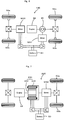
- Fig. 1 schematically illustrates the construction of a hybrid vehicle 20 with an engine misfire detection apparatus for an internal combustion engine mounted thereon in one embodiment of the invention.
- the hybrid vehicle 20 of the embodiment includes an engine 22, a three shaft-type power distribution integration mechanism 30 that is linked with a crankshaft 26 functioning as an output shaft of the engine 22 via a damper 28 functioning as a torsion element, a motor MG1 that is linked with the power distribution integration mechanism 30 and is capable of generating electric power, a reduction gear 35 that is attached to a ring gear shaft 32a functioning as a drive shaft connected with the power distribution integration mechanism 30, another motor MG2 that is linked with the reduction gear 35, and a hybrid electronic control unit 70 that controls the whole vehicle.
- the engine electronic control unit 24 for controlling the operations of the engine 22 mainly functions as the engine misfire detection apparatus for the internal combustion engine.
- the engine 22 is a six-cylinder internal combustion engine that consumes a hydrocarbon fuel, such as gasoline or light oil, to output power.
- a hydrocarbon fuel such as gasoline or light oil
- the air cleaned by an air cleaner 122 and taken in via a throttle valve 124 is mixed with the atomized gasoline injected by a fuel injection valve 126 included in every cylinder to the air-fuel mixture.
- the air-fuel mixture is introduced into a combustion chamber via an intake valve 128.
- the introduced air-fuel mixture is ignited with spark made by a spark plug 130 to be explosively combusted.
- the reciprocating motions of a piston 132 by the combustion energy are converted into rotational motions of a crankshaft 26.
- the exhaust from the engine 22 goes through a catalytic conversion unit 134 (filled with three-way catalyst) to convert toxic components included in the exhaust, that is, carbon monoxide (CO), hydrocarbons (HC), and nitrogen oxides (NOx), into harmless components, and is discharged to the outside air.
- a catalytic conversion unit 134 filled with three-way catalyst to convert toxic components included in the exhaust, that is, carbon monoxide (CO), hydrocarbons (HC), and nitrogen oxides (NOx), into harmless components, and is discharged to the outside air.
- the engine 22 is under control of an engine electronic control unit 24 (hereafter referred to as engine ECU 24).
- the engine ECU 24 is constructed as a microprocessor including a CPU 24a, a ROM 24b that stores processing programs, a RAM 24c that temporarily stores data, input and output ports (not shown), and a communication port (not shown) .
- the engine ECU 24 receives, via its input port (not shown), signals from various sensors that measure and detect the conditions of the engine 22.
- the signals input into the engine ECU 24 include a crank position from a crank position sensor 140 detected as the rotational position of the crankshaft 26, a cooling water temperature from a water temperature sensor 142 measured as the temperature of cooling water in the engine 22, a cam position from a cam position sensor 144 detected as the rotational position of a camshaft driven to open and close the intake valve 128 and an exhaust valve for gas intake and exhaust into and from the combustion chamber, a throttle valve position from a throttle valve position sensor 146 detected as the opening or position of the throttle valve 124, an air flow meter signal from an air flow meter 148 attached to an air intake conduit, an intake air temperature from a temperature sensor 149 attached to the air intake conduit, an air-fuel ratio AF from an air-fuel ratio sensor 135a and an oxygen signal from an oxygen sensor 135b.
- the engine ECU 24 outputs, via its output port (not shown), diverse control signals and driving signals to drive and control the engine 22, for example, driving signals to the fuel injection valve 126, driving signals to a throttle valve motor 136 for regulating the position of the throttle valve 124, control signals to an ignition coil 138 integrated with an igniter, and control signals to a variable valve timing mechanism 150 to vary the open and close timings of the intake valve 128.
- the engine ECU 24 communicates with the hybrid electronic control unit 70.
- the engine ECU 24 receives control signals from the hybrid electronic control unit 70 to drive and control the engine 22, while outputting data regarding the driving conditions of the engine 22 to the hybrid electronic control unit 70 according to the requirements.
- the power distribution and integration mechanism 30 has a sun gear 31 that is an external gear, a ring gear 32 that is an internal gear and is arranged concentrically with the sun gear 31, multiple pinion gears 33 that engage with the sun gear 31 and with the ring gear 32, and a carrier 34 that holds the multiple pinion gears 33 in such a manner as to allow free revolution thereof and free rotation thereof on the respective axes.
- the power distribution and integration mechanism 30 is constructed as a planetary gear mechanism that allows for differential motions of the sun gear 31, the ring gear 32, and the carrier 34 as rotational elements.
- the carrier 34, the sun gear 31, and the ring gear 32 in the power distribution and integration mechanism 30 are respectively coupled with the crankshaft 26 of the engine 22, the motor MG1, and the reduction gear 35 via ring gear shaft 32a.
- the motor MG1 functions as a generator
- the power output from the engine 22 and input through the carrier 34 is distributed into the sun gear 31 and the ring gear 32 according to the gear ratio.
- the motor MG1 functions as a motor
- the power output from the engine 22 and input through the carrier 34 is combined with the power output from the motor MG1 and input through the sun gear 31 and the composite power is output to the ring gear 32.
- the power output to the ring gear 32 is thus finally transmitted to the driving wheels 63a and 63b via the gear mechanism 60, and the differential gear 62 from ring gear shaft 32a.
- Both the motors MG1 and MG2 are known synchronous motor generators that are driven as a generator and as a motor.
- the motors MG1 and MG2 transmit electric power to and from a battery 50 via inverters 41 and 42.
- Power lines 54 that connect the inverters 41 and 42 with the battery 50 are constructed as a positive electrode bus line and a negative electrode bus line shared by the inverters 41 and 42. This arrangement enables the electric power generated by one of the motors MG1 and MG2 to be consumed by the other motor.
- the battery 50 is charged with a surplus of the electric power generated by the motor MG1 or MG2 and is discharged to supplement an insufficiency of the electric power.
- motor ECU 40 When the power balance is attained between the motors MG1 and MG2, the battery 50 is neither charged nor discharged. Operations of both the motors MG1 and MG2 are controlled by a motor electronic control unit (hereafter referred to as motor ECU) 40.
- the motor ECU 40 receives diverse signals required for controlling the operations of the motors MG1 and MG2, for example, signals from rotational position detection sensors 43 and 44 that detect the rotational positions of rotors in the motors MG1 and MG2 and phase currents applied to the motors MG1 and MG2 and measured by current sensors (not shown) .
- the motor ECU 40 outputs switching control signals to the inverters 41 and 42.
- the motor ECU 40 communicates with the hybrid electronic control unit 70 to control operations of the motors MG1 and MG2 in response to control signals transmitted from the hybrid electronic control unit 70 while outputting data relating to the operating conditions of the motors MG1 and MG2 to the hybrid electronic control unit 70 according to the requirements.
- the battery 50 is under control of a battery electronic control unit (hereafter referred to as battery ECU) 52.
- the battery ECU 52 receives diverse signals required for control of the battery 50, for example, an inter-terminal voltage measured by a voltage sensor (not shown) disposed between terminals of the battery 50, a charge-discharge current measured by a current sensor (not shown) attached to the power line 54 connected with the output terminal of the battery 50, and a battery temperature Tb measured by a temperature sensor 51 attached to the battery 50.
- the battery ECU 52 outputs data relating to the state of the battery 50 to the hybrid electronic control unit 70 via communication according to the requirements.
- the battery ECU 52 calculates a state of charge (SOC) of the battery 50, based on the accumulated charge-discharge current measured by the current sensor, for control of the battery 50.
- SOC state of charge
- the hybrid electronic control unit 70 is constructed as a microprocessor including a CPU 72, a ROM 74 that stores processing programs, a RAM 76 that temporarily stores data, and a non-illustrated input-output port, and a non-illustrated communication port.
- the hybrid electronic control unit 70 receives various inputs via the input port: an ignition signal from an ignition switch 80, a gearshift position SP from a gearshift position sensor 82 that detects the current position of a gearshift lever 81, an accelerator opening Acc from an accelerator pedal position sensor 84 that measures a step-on amount of an accelerator pedal 83, a brake pedal position BP from a brake pedal position sensor 86 that measures a step-on amount of a brake pedal 85, and a vehicle speed V from a vehicle speed sensor 88.
- the hybrid electronic control unit 70 communicates with the engine ECU 24, the motor ECU 40, and the battery ECU 52 via the communication port to transmit diverse control signals and data to and from the engine ECU 24, the motor ECU 40, and the battery ECU 52, as mentioned previously.
- the hybrid vehicle 20 of the embodiment thus constructed calculates a torque demand to be output to the ring gear shaft 32a functioning as the drive shaft, based on observed values of a vehicle speed V and an accelerator opening Acc, which corresponds to a driver's step-on amount of an accelerator pedal 83.
- the engine 22 and the motors MG1 and MG2 are subjected to operation control to output a required level of power corresponding to the calculated torque demand to the ring gear shaft 32a.
- the operation control of the engine 22 and the motors MG1 and MG2 selectively effectuates one of a torque conversion drive mode, a charge-discharge drive mode, and a motor drive mode.
- the torque conversion drive mode controls the operations of the engine 22 to output a quantity of power equivalent to the required level of power, while driving and controlling the motors MG1 and MG2 to cause all the power output from the engine 22 to be subjected to torque conversion by means of the power distribution integration mechanism 30 and the motors MG1 and MG2 and output to the ring gear shaft 32a.
- the charge-discharge drive mode controls the operations of the engine 22 to output a quantity of power equivalent to the sum of the required level of power and a quantity of electric power consumed by charging the battery 50 or supplied by discharging the battery 50, while driving and controlling the motors MG1 and MG2 to cause all or part of the power output from the engine 22 equivalent to the required level of power to be subjected to torque conversion by means of the power distribution integration mechanism 30 and the motors MG1 and MG2 and output to the ring gear shaft 32a, simultaneously with charge or discharge of the battery 50.
- the motor drive mode stops the operations of the engine 22 and drives and controls the motor MG2 to output a quantity of power equivalent to the required level of power to the ring gear shaft 32a.
- the motor MG1 performs rotation speed control to operate the engine 22 at a target rotation speed corresponding to a torque demand, while the motors MG1 and MG2 perform vibration control to reduce the potential vibration caused by the operation of the engine 22.
- the hybrid electronic control unit 70 sets a target rotation speed Ne* and a target torque Te* of the engine 22 corresponding to a torque demand, and sets a torque command Tm1* of the motor MG1 corresponding to a rotation adjustment torque Tn for operating the engine 22 at the target rotation speed Ne* and a vibration control torque Tv1 for reducing the potential vibration of the engine 22.
- the hybrid electronic control unit 70 also sets a torque command Tm2* of the motor MG2 corresponding to a drive torque Td, which depends upon a difference between a torque demand and a torque output from the engine 22 to the ring gear shaft 32a via the power distribution integration mechanism 30 with output of a torque from the motor MG1, and a vibration control torque Tv2 for reducing the potential vibration of the engine 22.
- the hybrid electronic control unit 70 then sends the settings of the target rotation speed Ne* and the target torque Te* of the engine 22 to the engine ECU 24, while sending the settings of the torque commands Tm1* and Tm2* of the motors MG1 and MG2 to the motor ECU 40.
- the engine ECU 24 receives the target rotation speed Ne* and the target torque Te* and performs fuel injection control and ignition control to drive the engine 22 at an operation point defined by the combination of the target rotation speed Ne* and the target torque Te*.
- the motor ECU 40 receives the torque commands Tm1* and Tm2* and performs switching control of switching elements included in the inverters 41 and 42 to operate the motors MG1 and MG2 with the respective torque commands Tm1* and Tm2*.
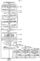
- Fig. 3 is a flowchart showing an engine misfire detection routine executed by the engine ECU 24.
- the engine misfire detection routine is performed repeatedly at preset time intervals during the operation of the engine 22.
- the description regards detection of a single engine misfire state having only one misfired cylinder among the six cylinders of the engine 22. It is assumed that the vibration control and the rotation speed control are under execution in a first cycle of this engine misfire detection routine.
- the CPU 24a of the engine ECU 24 first inputs a 30-degree rotation time T30 computed as a time period required for a 30-degree rotation of he crankshaft 26, a vibration control prohibition flag F1, and a rotation speed control prohibition flag F2 (step S100).
- the 30-degree rotation time T30 is computed according to a T30 computation routine shown in the flowchart of Fig. 4 .
- the vibration control prohibition flag F1 is set to 0 when the hybrid electronic control unit 70 gives permission for execution of the vibration control by the motors MG1 and MG2 to reduce the potential vibration caused by the operation of the engine 22.
- the vibration control prohibition flag F1 is set to 1 when the hybrid electronic control unit 70 prohibits the execution of the vibration control.
- the engine ECU 24 receives the setting of the vibration control prohibition flag F1 from the hybrid electronic control unit 70 by communication.
- the rotation speed control prohibition flag F2 is set to 0 when the hybrid electronic control unit 70 gives permission for execution of the rotation speed control by the motor MG1 to adjust the rotation speed of the engine 22.
- the rotation speed control prohibition flag F2 is set to 1 when the hybrid electronic control unit 70 prohibits the execution of the rotation speed control.
- the engine ECU 24 receives the setting of the rotation speed control prohibition flag F2 from the hybrid electronic control unit 70 by communication. Since the vibration control and the rotation speed control are being executed in the first cycle of this engine misfire detection routine, the vibration control prohibition flag F1 and the rotation speed control prohibition flag F2 input at step S100 are both equal to 0.
- the CPU 24a of the engine ECU 24 subsequently calculates a 360-degree difference ⁇ 360 of the input 30-degree rotation times T30 (step S110) and identifies the value of a single misfire tentative detection flag G (step S120) .
- the 360-degree difference ⁇ 360 is given as a difference between the currently input 30-degree rotation time T30 and a previous 30-degree rotation time T30 input 360 degrees before.
- the single misfire tentative detection flag G is set to 0 as an initial value and is set to 1 in response to tentative detection of a single misfire.
- the CPU 24a sets a threshold value A0 based on the settings of the vibration control prohibition flag F1 and the rotation speed control prohibition flag F2 (step S130) and compares the calculated 360-degree difference ⁇ 360 with the set threshold value A0 (step S140) .
- the threshold value A0 is empirically or otherwise determined as a criterion for tentative detection on the occurrence or the non-occurrence of a single misfire.
- the threshold value A0 is set to increase in the order of the combination of the vibration control prohibition flag F1 and the rotation speed control prohibition flag F2 both equal to 0, the combination of the vibration control prohibition flag F1 equal to 1 and the rotation speed control prohibition flag F2 equal to 0, and the combination of the vibration control prohibition flag F1 and the rotation speed control prohibition flag F2 both equal to 1. This is because a rotation variation of the crankshaft 26 in non-execution of the vibration control and the rotation speed control is significantly greater than that in execution of the vibration control and the rotation speed control.
- the threshold value A0 is set irrespective of execution or non-execution of the vibration control and the rotation speed control, the 360-degree difference ⁇ 360 in a normally fired cylinder may exceed the threshold value A0 in non-execution of the vibration control and the rotation speed control. Namely the fixed threshold value A0 may cause inaccurate tentative detection of an engine misfire.
- the vibration control prohibition flag F1 and the rotation speed control prohibition flag F2 are both equal to 0, the threshold value A0 is set corresponding to this combination of the vibration control prohibition flag F1 and the rotation speed control prohibition flag F2.
- the CPU 24a makes tentative detection of a single misfire and sets the single misfire tentative detection flag G to 1 (step S150), and subsequently sets a cylinder as the object of tentative detection of the single misfire to a misfired cylinder P3 (step S160) .
- the CPU 24a makes tentative detection of a single misfire and sets the single misfire tentative detection flag G to 1 (step S150), and subsequently sets a cylinder as the object of tentative detection of the single misfire to a misfired cylinder P3 (step S160) .
- explosive combustion of the air-fuel mixture takes place at the crank angle CA of every 120 degrees.
- the 360-degree difference ⁇ 360 between a large 30-degree rotation time T30 for a misfired cylinder and a small 30-degree rotation time T30 for a normally fired cylinder is greater than the 360-degree difference ⁇ 360 between 30-degree rotation times T30 for two normally fired cylinders.
- a peak of the 360-degree difference ⁇ 360 thus substantially corresponds to a misfired cylinder.
- a cylinder having a peak of the 360-degree difference ⁇ 360 is specified as the misfired cylinder P3.
- Fig. 5 shows a variation in 360-degree difference ⁇ 360 of the crank angle CA.
- a cylinder corresponding to a peak of the 360-degree difference ⁇ 360 is specified as the misfired cylinder P3.
- Cylinders explosively combusted immediately and second before the misfired cylinder P3 are respectively shown as pre-misfire cylinders P4 and P5.
- Cylinders explosively combusted immediately, second, and third after the misfired cylinder P3 are respectively shown as post-misfire cylinders P2, P1, and P0.
- the CPU 24a subsequently determines whether detection indexes Ja1, Ja2, and Ja3 used for final detection on the occurrence or the non-occurrence of a single misfire are computable (step S170) .
- the engine misfire detection routine is terminated immediately without any further processing.
- Computation of the detection indexes Ja1, Ja2, and Ja3 requires the 360-degree difference ⁇ 360 (P3) of the misfired cylinder P3 and the 360-degree differences ⁇ 360 of the post-misfire cylinders explosively combusted after the misfired cylinder P3 as described later in detail. This is the reason for the computability determination of the detection indexes Ja1, Ja2, and Ja3.
- the CPU 24a determines whether the detection indexes Ja1, Ja2, and Ja3 are computable (step S170).
- the detection index Ja1 represents a ratio ⁇ 360(P4)/ ⁇ 360(P3) of the 360-degree difference ⁇ 360(P4) of the pre-misfire cylinder P4 explosively combusted immediately before the misfired cylinder P3 to the 360-degree difference ⁇ 360(P3) of the misfired cylinder P3.
- the detection index Ja2 represents a ratio ⁇ 360(P2)/ ⁇ 360(P3) of the 360-degree difference ⁇ 360 (P2) of the post-misfire cylinder P2 explosively combusted immediately after the misfired cylinder P3 to the 360-degree difference ⁇ 360 (P3) of the misfired cylinder P3.
- the detection index Ja3 represents a ratio ⁇ 360(P0)/ ⁇ 360(P3) of the 360-degree difference ⁇ 360 (P0) of the post-misfire cylinder P0 explosively combusted third after the misfired cylinder P3 to the 360-degree difference ⁇ 360 (P3) of the misfired cylinder P3 .
- Threshold values A11, A12, A21, A22, A31, andA32 used for final detection on the occurrence or the non-occurrence of a single misfire are then set based on the settings of the vibration control prohibition flag F1 and the rotation speed control prohibition flag F2 (step S190) . It is then determined whether the computed detection indexes Ja1, Ja2, and Ja3 are respectively in a range defined by the threshold values A11 and A12, in a range defined by the threshold values A21 and A22, and in a range defined by the threshold values A31 and A32 (step S200) .
- the threshold values A11 and A12 are given respectively as a lower limit and an upper limit in a range of the ratio ⁇ 360(P4)/ ⁇ 360(P3) of the 360-degree difference ⁇ 360(P4) of the pre-misfire cylinder P4 explosively combusted immediately before the misfired cylinder P3 to the 360-degree difference ⁇ 360 (P3) of the misfired cylinder P3.
- the threshold values A21 and A22 are given respectively as a lower limit and an upper limit in a range of the ratio ⁇ 360(P2)/ ⁇ 360(P3) of the 360-degree difference ⁇ 360(P2) of the post-misfire cylinder P2 explosively combusted immediately after the misfired cylinder P3 to the 360-degree difference ⁇ 360(P3) of the misfired cylinder P3.
- the threshold values A31 and A32 are given respectively as a lower limit and an upper limit in a range of the ratio ⁇ 360(P0)/ ⁇ 360(P3) of the 360-degree difference ⁇ 360 (P0) of the post-misfire cylinder P0 explosively combusted third after the misfired cylinder P3 to the 360-degree difference ⁇ 360 (P3) of the misfired cylinder P3.
- the threshold values A11, A12, A21, A22, A31, and A32 are experimentally or otherwise determined according to the settings of the vibration control prohibition flag F1 and the rotation speed control prohibition flag F2.
- the threshold values A11, A12, A21, A22, A31, and A32 are set based on the settings of the vibration control prohibition flag F1 and the rotation speed control prohibition flag F2.
- the vibration control prohibition flag F1 and the rotation speed control prohibition flag F2 are both equal to 0
- the threshold values A11, A12, A21, A22, A31, and A32 are set corresponding to this combination of the vibration control prohibition flag F1 and the rotation speed control prohibition flag F2.
- the CPU 24a makes final detection of a single misfire (step S210) and terminates the engine misfire detection routine.
- the CPU 24a does not make final detection of a single misfire but checks the value of the vibration control prohibition flag F1 (step S220) .
- the CPU 24a sends a vibration control prohibition command to the hybrid electronic control unit 70 (step S230), sets the single misfire tentative detection flag G to 0 (step S240), and terminates the engine misfire detection routine.
- the hybrid electronic control unit 70 identifies prohibition of the execution of the vibration control in response to reception of the vibration control prohibition command, sets the vibration control prohibition flag F1 to 1, and calculates the torque commands Tm1* and Tm2* of the motors MG1 and MG2 without taking into account the vibration control torques Tv1 and Tv2.
- the threshold value A0 is set corresponding to the combination of the vibration control prohibition flag F1 set to 1 and the rotation speed control prohibition flag F2 set to 0 (step S130).
- the CPU 24a successively sets the cylinder having the 360-degree difference ⁇ 360 over the newly set threshold value A0 as the misfired cylinder P3 (steps S140 to S160), computes the detection indexes Ja1, Ja2, and Ja3 (step S180), and sets the threshold values A11, A12, A21, A22, A31, and A32 corresponding to the combination of the vibration control prohibition flag F1 set to 1 and the rotation speed control prohibition flag F2 set to 0 (step S190) .
- the CPU 24a determines whether the computed detection indexes Ja1, Ja2, and Ja3 are respectively in the range defined by the newly set threshold values A11 and A12, in the range defined by the newly set threshold values A21 and A22, and in the range defined by the newly set threshold values A31 and A32 (step S200) .
- the CPU 24a makes final detection of a single misfire (step S210) and terminates the engine misfire detection routine.
- the procedure of this embodiment makes final detection on the occurrence or the non-occurrence of a single misfire in non-execution of the vibration control when there is no final detection of a single misfire in execution of the vibration control and the rotation speed control.
- This arrangement desirably increases the detection frequency of single misfires, compared with the conventional procedure of terminating detection of a single misfire when there is no final detection of a single misfire in execution of the vibration control and the rotation speed control.
- the CPU 24a Upon determination at step S200 that any of the computed detection indexes Ja1, Ja2, and Ja3 is out of the range defined by the threshold values A11 and A12, the range defined by the threshold values A21 and A22, or the range defined by the threshold values A31 and A32, on the other hand, the CPU 24a does not make final detection of a single misfire but checks the value of the vibration control prohibition flag F1 (step S220) . In this cycle, since the vibration control prohibition flag F1 is set equal to 1, the CPU 24a subsequently checks the value of the rotation speed control prohibition flag F2 (step S250).
- the CPU 24a sends a rotation speed control prohibition command to the hybrid electronic control unit 70 (step S260), sets the single misfire tentative detection flag G to 0 (step S270), and terminates the engine misfire detection routine.
- the hybrid electronic control unit 70 identifies prohibition of the execution of the rotation speed control in response to reception of the rotation speed control prohibition command, sets the rotation speed control prohibition flag F2 to 1 with the vibration control prohibition flag F1 kept to 1, and calculates the torque command Tm1* of the motor MG1 without taking into account the vibration control torque Tv1 and the rotation adjustment torque Tn. In this case, the torque command Tm1* of the motor MG1 is set equal to 0. There is no torque output from the motor MG1, so that the power of the engine 22 is not output to the ring gear shaft 32a or the driveshaft.
- the threshold value A0 is set corresponding to the combination of the vibration control prohibition flag F1 and the rotation speed control prohibition flag F2 both set to 1 (step S130).
- the CPU 24a successively sets the cylinder having the 360-degree difference ⁇ 360 over the newly set threshold value A0 as the misfired cylinder P3 (steps S140 to S160), computes the detection indexes Ja1, Ja2, and Ja3 (step S180), and sets the threshold values A11, A12, A21, A22, A31, and A32 corresponding to the combination of the vibration control prohibition flag F1 and the rotation speed control prohibition flag F2 both set to 1 (step S190) .
- the CPU 24a determines whether the computed detection indexes Ja1, Ja2, and Ja3 are respectively in the range defined by the newly set threshold values A11 and A12, in the range defined by the newly set threshold values A21 and A22, and in the range defined by the newly set threshold values A31 and A32 (step S200) .
- the CPU 24a makes final detection of a single misfire (step S210) and terminates the engine misfire detection routine.
- the procedure of this embodiment makes final detection on the occurrence or the non-occurrence of a single misfire in non-execution of the rotation speed control when there is no final detection of a single misfire in execution of the rotation speed control.
- This arrangement desirably increases the detection frequency of single misfires, compared with the conventional procedure of terminating detection of a single misfire when there is no final detection of a single misfire in execution of the rotation speed control.
- the CPU 24a Upon determination at step S200 that any of the computed detection indexes Ja1, Ja2, and Ja3 is out of the range defined by the threshold values A11 and A12, the range defined by the threshold values A21 and A22, or the range defined by the threshold values A31 and A32, on the other hand, the CPU 24a does not make final detection of a single misfire but checks the values of the vibration control prohibition flag F1 and the rotation speed control prohibition flag F2 (steps S220 and S250) .
- the CPU 24a sends a vibration control prohibition cancel command and a rotation speed control prohibition cancel command to the hybrid electronic control unit 70 (step S280), sets the single misfire tentative detection flag G to 0 (step S290), and terminates the engine misfire detection routine.
- the hybrid electronic control unit 70 identifies permission for the execution of both the vibration control and the rotation speed control in response to reception of the vibration control prohibition cancel command and the rotation speed control prohibition cancel command, and sets the torque commands Tm1* and Tm2* of the motors MG1 and MG2 with taking into account the vibration control torques Tv1 and Tv2 and the rotation adjustment torque Tn.
- the procedure of the embodiment detects the non-occurrence of a single misfire and resumes the execution of the vibration control and the rotation speed control.
- the engine misfire detection apparatus for the internal combustion engine mounted on the hybrid vehicle 20 of the embodiment makes tentative detection on the occurrence or the non-occurrence of a single misfire based on the 360-degree difference ⁇ 360 of the 30-degree rotation time T30 computed as the time period required for every 30-degree rotation of the crankshaft 26.
- the engine misfire detection apparatus makes final detection on the occurrence or the non-occurrence of a single misfire based on the 360-degree difference ⁇ 360 of the 30-degree rotation time T30.
- the engine misfire detection apparatus When there is no final detection of a single misfire in execution of the vibration control and the rotation speed control, the engine misfire detection apparatus sends the vibration control prohibition command to the hybrid electronic control unit 70 and makes final detection on the occurrence or the non-occurrence of a single misfire in non-execution of the vibration control. When there is no final detection of a single misfire in non-execution of the vibration control, the engine misfire detection apparatus sends the rotation speed control prohibition command to the hybrid electronic control unit 70 and makes final detection on the occurrence or the non-occurrence of a single misfire in non-execution of both the vibration control and the rotation speed control.
- the engine misfire detection apparatus of the invention makes final detection on the occurrence or the non-occurrence of a single misfire again in non-execution of the vibration control or in non-execution of both the vibration control and the rotation speed control.
- This arrangement desirably increases the detection frequency of single misfires.
- the threshold value A0 and the threshold values A11, A12, A21, A22, A31, and A32, which are set depending on the execution or the non-execution of the vibration control and the rotation speed control, are used for the tentative detection and the final detection on the occurrence or the non-occurrence of a single misfire of the engine 22. This arrangement ensures the adequate detection of a single misfire.
- the above embodiment regards detection of a single misfire where only one cylinder among the six cylinders of the engine 22 is misfired.
- the engine misfire detection apparatus for the internal combustion engine mounted on the hybrid vehicle 20 is also applicable to detect engine misfires other than a single misfire, for example, consecutive misfires where two consecutive cylinders among the six cylinders of the engine 22 are misfired or intermittent misfires where two cylinders located across one fired cylinder among the six cylinders of the engine 22 are misfired.
- the engine misfire detection technique desirably increases the detection frequency of engine misfires and ensures the adequate detection of engine misfires.
- the rotation speed control prohibition command is sent to the hybrid electronic control unit 70 to make final detection on the occurrence or the non-occurrence of an engine misfire in non-execution of both the vibration control and the rotation speed control.
- One modified procedure may detect the non-occurrence of any misfire in the engine 22 without sending the rotation speed control prohibition command to the hybrid electronic control unit 70.
- the procedure of the embodiment makes tentative detection on the occurrence or the non-occurrence of a misfire of the engine 22 based on the 30-degree rotation time T30 and the threshold value A0 in non-execution of the vibration control and, in response to the tentative detection of an engine misfire, makes final detection on the occurrence or the non-occurrence of a misfire of the engine 22 based on the detection indexes Ja1, Ja2, and Ja3 and the threshold values A11, A12, A21, A22, A31, and A32.
- one modified procedure may not make tentative detection in non-execution of the vibration control or the rotation speed control but may immediately make final detection on the occurrence or the non-occurrence of a misfire of the engine 22 based on the detection indexes Ja1, Ja2, and Ja3 and the threshold values A11, A12, A21, A22, A31, and A32.
- the misfired cylinder P3 specified in response to the tentative detection of a misfire of the engine 22 in execution of the vibration control and the rotation speed control may be kept as the misfired cylinder P3, or a cylinder having a peak of the 360-degree difference ⁇ 360 may be newly specified as the misfired cylinder P3.
- the procedure of the embodiment uses the threshold value A0 set depending on the execution or the non-execution of the vibration control and the rotation speed control.
- the threshold value A0 may, however, be fixed to a constant value regardless of the execution or the non-execution of the vibration control and the rotation speed control.
- the procedure of the embodiment makes final detection of a misfire of the engine 22 when the detection indexes Ja1, Ja2, and Ja3 are respectively in the range defined by the threshold values A11 and A12, in the range defined by the threshold values A21 and A22, and in the range defined by the threshold values A31 and A32.
- An additional condition that the air-fuel ratio measured by an air-fuel ratio sensor 135a is within a specific range including a preset air-fuel ratio may be given for the final detection of a misfire of the engine 22.
- the preset air-fuel ratio may be a stoichiometric air-fuel ratio (about 14.7), and the specific range maybe experimentally or otherwise determined.
- the procedure of the embodiment makes final detection on the occurrence or the non-occurrence of a misfire of the engine 22 in non-execution of the vibration control by means of the motors MG1 and MG2.
- one modified procedure may make final detection on the occurrence or the non-occurrence of a misfire of the engine 22 in non-execution of the vibration control by one of the motors MG1 and MG2 (for example, the motor MG1) and execution of the vibration control by only the other of the motors MG1 and MG2 (for example, the motor MG2).
- the modified procedure may make final detection on the occurrence or the non-occurrence of a misfire of the engine 22 in non-execution of the vibration control by any of the motors MG1 and MG2.
- both the motors MG1 and MG2 take charge of the vibration control. Only one of the motors MG1 and MG2 may alternatively take charge of the vibration control.
- the engine misfire detection apparatus for the internal combustion engine mounted on the hybrid vehicle 20 of the embodiment makes the tentative detection and the final detection, based on the 360-degree differences ⁇ 360 calculated from the 30-degree rotation time T30.
- the 360-degree differences ⁇ 360 is, however, not essential for the tentative detection or the final detection of an engine misfire.
- a 60-degree difference ⁇ 60 given as a difference between the currently input 30-degree rotation time T30 and a previous 30-degree rotation time T30 input 60 degrees before, a 120-degree difference ⁇ 120 given as a difference between the currently input 30-degree rotation time T30 and a previous 30-degree rotation time T30 input 120 degrees before, or a 720-degree difference ⁇ 720 given as a difference between the currently input 30-degree rotation time T30 and a previous 30-degree rotation time T30 input 720 degrees before may be used for the same purpose, in addition to or in place of the 360-degree differences ⁇ 360.
- the engine misfire detection apparatus for the internal combustion engine mounted on the hybrid vehicle 20 of the embodiment performs the tentative detection and the final detection of an engine misfire based on the 360-degree difference ⁇ 360 of the 30-degree rotation time T30 computed as the time period required for every 30-degree rotation of the crankshaft 26.
- the 360-degree difference ⁇ 360 is, however, not essential, but the engine misfire detection apparatus may perform the tentative detection and the final detection of an engine misfire based on any other T30-related factor or directly based on the 30-degree rotation time T30.
- the 30-degree rotation time T30 may be replaced by a 15-degree rotation time T15 computed as a time period required for every 15-degree rotation of the crankshaft 26 or by a 60-degree rotation time T60 computed as a time period required for every 60-degree rotation of the crankshaft 26.
- the engine misfire detection apparatus mounted on the hybrid vehicle 20 of the embodiment detects a misfire of the six cylinder engine 22.
- the six cylinder engine is, however, not essential, but the engine misfire detection apparatus may be applicable to an internal combustion engine having any number of multiple cylinders, for example, a four cylinder engine or an eight cylinder engine.
- the embodiment regards the engine misfire detection apparatus for the engine 22 mounted on the hybrid vehicle 20, which is equipped with the power distribution integration mechanism 30 connected to the crankshaft 26 of the engine 22, to the rotating shaft of the motor MG1, and to the ring gear shaft 32a or the driveshaft and with the motor MG2 connected to the ring gear shaft 32a via the reduction gear 35.
- the engine misfire detection apparatus for the engine 22 may be mounted on a hybrid vehicle 120 of one modified structure shown in Fig. 6 .
- the power of the motor MG2 is connected to another axle (an axle linked with wheels 64a and 64b) that is different from the axle connecting with the ring gear shaft 32a (the axle linked with the drive wheels 63a and 63b).
- the engine misfire detection apparatus for the engine 22 may also be mounted on a hybrid vehicle 220 of another modified structure shown in Fig. 7 .
- the hybrid vehicle 220 of Fig. 7 is equipped with a pair-rotor motor 230.
- the pair-rotor motor 230 includes an inner rotor 232 connected to the crankshaft 26 of the engine 22 and an outer rotor 234 connected to a driveshaft of outputting power to the drive wheels 63a and 63b.
- the pair-rotor motor 230 transmits part of the output power of the engine 22 to the driveshaft, while converting the residual engine output power into electric power.
- the embodiment described above regards the engine misfire detection apparatus adopted in the power output apparatus including the engine 22, the power distribution integration mechanism 30, and the motors MG1 and MG2.
- the power output apparatus is not restricted to this configuration.
- the engine misfire detection apparatus may be adopted in the power output apparatus of any configuration that includes an internal combustion engine having an output shaft linked to a driveshaft and a motor enabling input and output of power from and to the output shaft of the internal combustion engine and ensures output of at least part of the output power of the internal combustion engine to the driveshaft under vibration control of controlling the motor to reduce the potential vibration of the internal combustion engine.
- the technique of the invention is preferably applied to the manufacturing industries of various equipment and apparatuses including a built-in internal combustion engine as well as automobiles equipped with an internal combustion engine.
Landscapes
- Engineering & Computer Science (AREA)
- Chemical & Material Sciences (AREA)
- Combustion & Propulsion (AREA)
- Mechanical Engineering (AREA)
- Transportation (AREA)
- General Engineering & Computer Science (AREA)
- Automation & Control Theory (AREA)
- Power Engineering (AREA)
- General Health & Medical Sciences (AREA)
- Biomedical Technology (AREA)
- Life Sciences & Earth Sciences (AREA)
- Sustainable Development (AREA)
- Sustainable Energy (AREA)
- Health & Medical Sciences (AREA)
- Physics & Mathematics (AREA)
- General Physics & Mathematics (AREA)
- Combined Controls Of Internal Combustion Engines (AREA)
- Hybrid Electric Vehicles (AREA)
- Control Of Vehicle Engines Or Engines For Specific Uses (AREA)
Claims (8)
- Appareil de détection de raté d'allumage de moteur qui permet de détecter un raté d'allumage d'un moteur à combustion interne (22) dans un appareil d'alimentation en énergie qui comprend le moteur à combustion interne qui possède un arbre de sortie (26) relié à un arbre de transmission (32a) et un moteur (MG1) qui permet l'admission et la transmission d'énergie de la part de et à l'arbre de sortie du moteur à combustion interne et qui garantit la fourniture d'au moins une partie de la puissance de sortie du moteur à combustion interne à l'arbre de transmission avec un contrôle des vibrations qui consiste à contrôler le moteur de façon à réduire une vibration provoquée par le fonctionnement du moteur à combustion interne,
dans lequel l'appareil de détection de raté d'allumage de moteur comprend :un détecteur de position de rotation (140) qui détecte une position de rotation de l'arbre de sortie du moteur à combustion interne ;un calculateur de durée de rotation à un angle précis (70) qui calcule une durée de rotation à un angle précis nécessaire à la rotation de l'arbre de sortie du moteur à combustion interne selon chaque angle de rotation prédéterminé en fonction de la position de rotation détectée ;un détecteur de rapport air/carburant (135a) qui mesure un rapport air/carburant sous forme de rapport entre le carburant et l'air fourni au moteur à combustion interne,un module de détection de tentative de raté d'allumage de moteur (70) qui effectue une détection de tentative lors de l'occurrence ou de la non-occurrence d'un raté d'allumage dans le moteur à combustion interne sur la base de la durée de rotation à un angle précis calculée ;un premier module de détection finale de raté d'allumage de moteur (70) qui, en réponse à la détection de tentative de raté d'allumage dans le moteur à combustion interne par le module de détection de tentative de raté d'allumage de moteur, effectue une détection finale lors de l'occurrence ou de la non-occurrence d'un raté d'allumage dans le moteur à combustion interne sur la base de la durée de rotation à un angle précis calculée et du rapport air/carburant mesuré, dans lequel le premier module de détection finale de raté d'allumage de moteur n'effectue aucune détection finale d'un raté d'allumage dans le moteur à combustion interne lorsque le rapport air/carburant mesuré est en-dehors d'une plage spécifique qui comprend un rapport air/carburant prédéfini ; etun second module de détection finale de raté d'allumage de moteur (70) qui, en l'absence de détection finale d'un raté d'allumage dans le moteur à combustion interne par le premier module de détection finale de raté d'allumage de moteur, interdit l'exécution du contrôle des vibrations et, après l'interdiction d'exécution du contrôle des vibrations, effectue une détection finale lors de l'occurrence ou de la non-occurrence d'un raté d'allumage dans le moteur à combustion interne sur la base de la durée de rotation à un angle précis calculée. - Appareil de détection de raté d'allumage de moteur selon la revendication 1, dans lequel le module de détection de tentative de raté d'allumage de moteur effectue une détection de tentative lors de l'occurrence ou de la non-occurrence d'un raté d'allumage dans le moteur à combustion interne sur la base de la durée de rotation à un angle précis calculée et d'une première valeur de seuil prédéfinie, et
le second module de détection finale de raté d'allumage de moteur, après l'interdiction d'exécution du contrôle des vibrations, effectue une détection de tentative lors de l'occurrence ou de la non-occurrence d'un raté d'allumage dans le moteur à combustion interne sur la base de la durée de rotation à un angle précis calculée et d'une seconde valeur de seuil prédéfinie qui est différente de la première valeur de seuil, et, en réponse à la détection de tentative d'un raté d'allumage du moteur à combustion interne, effectue une détection finale lors de l'occurrence ou de la non-occurrence d'un raté d'allumage dans le moteur à combustion interne sur la base de la durée de rotation à un angle précis calculée. - Appareil de détection de raté d'allumage de moteur selon la revendication 2, dans lequel le module de détection de tentative de raté d'allumage de moteur calcule successivement une première différence entre une durée de rotation à un angle précis actuelle calculée dans une position actuelle de l'arbre de sortie et une durée de rotation à un angle précis antérieure calculée dans une position antérieure de l'arbre de sortie qui est une première position de rotation située avant la position actuelle, et effectue une détection de tentative d'un raté d'allumage dans le moteur à combustion interne lorsqu'une quelconque des premières différences calculées successivement est supérieure à la première valeur de seuil,
le premier module de détection finale de moteur spécifie la première différence qui est supérieure à la première valeur de seuil en guise de première différence d'objet et effectue une détection finale d'un raté d'allumage dans le moteur à combustion interne lorsqu'un rapport entre une première différence choisie parmi les premières différences calculées successivement et la première différence d'objet se trouve sur une première plage prédéfinie, et
le second module de détection finale de raté d'allumage de moteur, après l'interdiction d'exécution du contrôle des vibrations, calcule successivement une seconde différence entre une durée de rotation à un angle précis actuelle calculée dans une position actuelle de l'arbre de sortie et une durée de rotation à un angle précis antérieure calculée dans une position antérieure de l'arbre de sortie qui est la première position de rotation située avant la position actuelle, effectue une détection de tentative d'un raté d'allumage dans le moteur à combustion interne lorsqu'une quelconque des secondes différences successivement calculées est supérieure à la seconde valeur de seuil, et, en réponse à la détection de tentative d'un raté d'allumage dans le moteur à combustion interne, spécifie la seconde différence qui est supérieure à la seconde valeur de seuil en guide de seconde différence d'objet et effectue une détection finale de raté d'allumage dans le moteur à combustion interne lorsqu'un rapport entre une seconde différence choisie parmi les secondes différences successivement calculées et la seconde différence d'objet se trouve sur une seconde plage prédéfinie qui est différente de la première plage. - Appareil de détection de raté d'allumage de moteur selon la revendication 1, dans lequel l'appareil d'alimentation en énergie exécute une commande de vitesse de rotation qui consiste à contrôler le moteur afin d'ajuster une vitesse de rotation du moteur à combustion interne,
dans lequel l'appareil de détection de raté d'allumage de moteur possède en outre :un troisième module de détection finale de raté d'allumage de moteur (70) qui, en cas d'absence de détection finale d'un raté d'allumage dans le moteur à combustion interne par le second module de détection finale de raté d'allumage de moteur, interdit l'exécution de la commande de vitesse de rotation et, après l'interdiction d'exécution de la commande de vitesse de rotation, effectue une détection finale lors de l'occurrence ou de la non-occurrence d'un raté d'allumage dans le moteur à combustion interne sur la base de la durée de rotation à un angle précis calculée. - Appareil de détection de raté d'allumage de moteur selon la revendication 1, dans lequel l'appareil d'alimentation en énergie exécute une commande de vitesse de rotation qui consiste à contrôler le moteur afin d'ajuster une vitesse de rotation du moteur à combustion interne,
le module de détection de tentative de raté d'allumage de moteur effectue une détection de tentative lors de l'occurrence ou de la non-occurrence d'un raté d'allumage dans le moteur à combustion interne sur la base de la durée de rotation à un angle précis calculée et d'une première valeur de seuil prédéfinie, et
le second module de détection finale de raté d'allumage de moteur, après l'interdiction d'exécution du contrôle des vibrations, effectue une détection de tentative lors de l'occurrence ou de la non-occurrence d'un raté d'allumage dans le moteur à combustion interne sur la base de la durée de rotation à un angle précis calculée et d'une seconde valeur de seuil prédéfinie qui est différente de la première valeur de seuil, et, en réponse à la détection de tentative d'un raté d'allumage du moteur à combustion interne, effectue une détection finale lors de l'occurrence ou de la non-occurrence d'un raté d'allumage dans le moteur à combustion interne sur la base de la durée de rotation à un angle précis calculée,
dans lequel l'appareil de détection de raté d'allumage de moteur possède en outre :un troisième module de détection finale de raté d'allumage de moteur (70) qui, en cas d'absence de détection finale d'un raté d'allumage dans le moteur à combustion interne par le second module de détection finale de raté d'allumage de moteur, interdit l'exécution de la commande de vitesse de rotation, effectue une détection de tentative lors de l'occurrence ou de la non-occurrence d'un raté d'allumage dans le moteur à combustion interne sur la base de la durée de rotation à un angle précis calculée et d'une troisième valeur de seuil prédéfinie qui est différente de la première valeur de seuil et de la seconde valeur de seuil après l'interdiction d'exécution de la commande de vitesse de rotation, et, en réponse à la détection de tentative d'un raté d'allumage du moteur à combustion interne, effectue une détection finale lors de l'occurrence ou de la non-occurrence d'un raté d'allumage dans le moteur à combustion interne sur la base de la durée de rotation à un angle précis calculée. - Appareil de détection de raté d'allumage de moteur selon la revendication 5, dans lequel le module de détection de tentative de raté d'allumage de moteur calcule successivement une première différence entre une durée de rotation à un angle précis actuelle calculée dans une position actuelle de l'arbre de sortie et une durée de rotation à un angle précis antérieure calculée dans une position antérieure de l'arbre de sortie qui est une première position de rotation située avant la position actuelle, et effectue une détection de tentative d'un raté d'allumage dans le moteur à combustion interne lorsqu'une quelconque des premières différences successivement calculées est supérieure à la première valeur de seuil,
le premier module de détection finale de raté d'allumage de moteur spécifie la première différence qui est supérieure à la première valeur de seuil en guise de première différence d'objet et effectue une détection finale d'un raté d'allumage dans le moteur à combustion interne lorsqu'un rapport entre une première différence choisie parmi les premières différences calculées successivement et la première différence d'objet se trouve sur une première plage prédéfinie, et
le second module de détection finale de raté d'allumage de moteur, après l'interdiction d'exécution du contrôle des vibrations, calcule successivement une seconde différence entre une durée de rotation à un angle précis actuelle calculée dans une position actuelle de l'arbre de sortie et une durée de rotation à un angle précis antérieure calculée dans une position antérieure de l'arbre de sortie qui est la première position de rotation située avant la position actuelle, effectue une détection de tentative d'un raté d'allumage dans le moteur à combustion interne lorsqu'une quelconque des secondes différences successivement calculées est supérieure à la seconde valeur de seuil, et, en réponse à la détection de tentative d'un raté d'allumage dans le moteur à combustion interne, spécifie la seconde différence qui est supérieure à la seconde valeur de seuil en guise de seconde différence d'objet et effectue une détection finale de raté d'allumage dans le moteur à combustion interne lorsqu'un rapport entre une seconde différence choisie parmi les secondes différences successivement calculées et la seconde différence d'objet se trouve sur une seconde plage prédéfinie qui est différente de la première plage, et
le troisième module de détection finale de raté d'allumage de moteur, après l'interdiction d'exécution de la commande de vitesse de rotation, calcule successivement une troisième différence entre une durée de rotation à un angle précis actuelle calculée dans une position actuelle de l'arbre de sortie et une durée de rotation à un angle précis antérieure calculée dans une position antérieure de l'arbre de sortie qui est la première position de rotation située avant la position actuelle, effectue une détection de tentative d'un raté d'allumage dans le moteur à combustion interne lorsqu'une quelconque des troisièmes différences calculées successivement est supérieure à la troisième valeur de seuil, et, en réponse à la détection de tentative d'un raté d'allumage dans le moteur à combustion interne, spécifie la troisième différence qui est supérieure à la troisième valeur de seuil en guise de troisième différence d'objet et effectue une détection finale d'un raté d'allumage dans le moteur à combustion interne lorsqu'un rapport entre une troisième différence choisie parmi les troisièmes différences successivement calculées et la troisième différence d'objet se trouve sur une troisième plage prédéfinie qui est différente de la première plage et de la seconde plage. - Appareil de détection de raté d'allumage de moteur selon la revendication 1, dans lequel l'appareil d'alimentation en énergie comprend un second moteur (MG2) qui permet l'admission et la transmission d'énergie de la part de et à l'arbre de transmission et qui contrôle le moteur et le second moteur afin d'exécuter le contrôle des vibrations, et
le second module de détection finale de raté d'allumage de moteur interdit l'exécution du contrôle des vibrations à l'aide d'un moteur situé entre le moteur et le second moteur, effectue une détection finale lors de l'occurrence ou de la non-occurrence d'un raté d'allumage dans le moteur à combustion interne sur la base de la durée de rotation à un angle précis calculée après l'interdiction d'exécution du contrôle des vibrations par le moteur, et, en cas d'absence de détection finale d'un raté d'allumage dans le moteur à combustion interne, interdit l'exécution du contrôle des vibrations par l'autre moteur situé entre le moteur et le second moteur et effectue une détection finale lors de l'occurrence ou de la non-occurrence d'un raté d'allumage dans le moteur à combustion interne sur la base de la durée de rotation à un angle précis calculée après l'interdiction d'exécution du contrôle des vibrations par l'autre moteur. - Procédé de détection de raté d'allumage de moteur qui consiste à détecter un raté d'allumage d'un moteur à combustion interne (22) dans un appareil d'alimentation en énergie qui comprend le moteur à combustion interne qui possède un arbre de sortie (26) relié à un arbre de transmission (32a) et un moteur (MG1) qui permet l'admission et la transmission d'énergie de la part de et à l'arbre de sortie du moteur à combustion interne et garantit la fourniture d'au moins une partie de la puissance de sortie du moteur à combustion interne à l'arbre de transmission avec un contrôle des vibrations qui consiste à contrôler le moteur de façon à réduire une vibration provoquée par le fonctionnement du moteur à combustion interne,
dans lequel le procédé de détection de raté d'allumage de moteur comprend :la mesure d'un rapport air/carburant sous forme de rapport entre un carburant et l'air fourni au moteur à combustion interne,(a) le calcul d'une durée de rotation à un angle précis nécessaire à la rotation de l'arbre de sortie du moteur à combustion interne selon chaque angle de rotation prédéterminé en fonction d'une position de rotation de l'arbre de sortie du moteur à combustion interne (S100) ;(b) la réalisation d'une détection de tentative lors de l'occurrence ou de la non-occurrence d'un raté d'allumage dans le moteur à combustion interne sur la base de la durée de rotation à un angle précis calculée (S150) ;(c) en réponse à la détection de tentative d'un raté d'allumage dans le moteur à combustion interne à l'étape (b), la réalisation d'une détection finale lors de l'occurrence ou de la non-occurrence d'un raté d'allumage dans le moteur à combustion interne sur la base de la durée de rotation à un angle précis calculée et du rapport air/carburant mesuré (S200), dans lequel le premier module de détection finale de raté d'allumage de moteur n'effectue aucune détection finale d'un raté d'allumage dans le moteur à combustion interne lorsque le rapport air/carburant mesuré se trouve en-dehors d'une plage spécifique qui comprend un rapport air/carburant spécifique ; et(d) en cas d'absence de détection finale d'un raté d'allumage dans le moteur à combustion interne à l'étape (c), l'interdiction d'exécution du contrôle des vibrations (S230) et, après l'interdiction d'exécution du contrôle des vibrations, la réalisation d'une détection finale lors de l'occurrence et de la non-occurrence d'un raté d'allumage dans le moteur à combustion interne sur la base de la durée de rotation à un angle précis calculée.
Applications Claiming Priority (2)
| Application Number | Priority Date | Filing Date | Title |
|---|---|---|---|
| JP2006208074A JP4007401B1 (ja) | 2006-07-31 | 2006-07-31 | 内燃機関の失火判定装置および失火判定方法 |
| PCT/JP2007/062974 WO2008015860A1 (fr) | 2006-07-31 | 2007-06-28 | Dispositif et procédé de détermination de raté d'allumage dans un moteur à combustion interne |
Publications (3)
| Publication Number | Publication Date |
|---|---|
| EP2048054A1 EP2048054A1 (fr) | 2009-04-15 |
| EP2048054A4 EP2048054A4 (fr) | 2017-12-13 |
| EP2048054B1 true EP2048054B1 (fr) | 2018-11-21 |
Family
ID=38769852
Family Applications (1)
| Application Number | Title | Priority Date | Filing Date |
|---|---|---|---|
| EP07767768.0A Active EP2048054B1 (fr) | 2006-07-31 | 2007-06-28 | Dispositif et procédé de détermination de raté d'allumage dans un moteur à combustion interne |
Country Status (4)
| Country | Link |
|---|---|
| US (1) | US8041502B2 (fr) |
| EP (1) | EP2048054B1 (fr) |
| JP (1) | JP4007401B1 (fr) |
| WO (1) | WO2008015860A1 (fr) |
Families Citing this family (18)
| Publication number | Priority date | Publication date | Assignee | Title |
|---|---|---|---|---|
| JP4492549B2 (ja) * | 2006-01-27 | 2010-06-30 | トヨタ自動車株式会社 | 失火判定装置、ハイブリッド自動車及び失火判定方法 |
| JP4222414B2 (ja) * | 2006-12-04 | 2009-02-12 | トヨタ自動車株式会社 | 動力出力装置、それを備えたハイブリッド自動車、および動力出力装置の制御方法 |
| JP2009280082A (ja) * | 2008-05-22 | 2009-12-03 | Honda Motor Co Ltd | 車両の制御装置 |
| JP5108719B2 (ja) * | 2008-10-31 | 2012-12-26 | 株式会社日本自動車部品総合研究所 | 内燃機関の失火判定装置 |
| JP5187362B2 (ja) * | 2010-08-20 | 2013-04-24 | トヨタ自動車株式会社 | 車両の制御装置 |
| EP2664509B1 (fr) * | 2011-01-12 | 2016-03-16 | Toyota Jidosha Kabushiki Kaisha | Véhicule et procédé de commande de véhicule |
| JP5705765B2 (ja) * | 2012-02-23 | 2015-04-22 | 三菱重工業株式会社 | ガスエンジンの制御装置および方法 |
| JP5962758B2 (ja) * | 2012-06-14 | 2016-08-03 | 日産自動車株式会社 | 内燃機関の制御装置 |
| DE112012007010B4 (de) * | 2012-10-12 | 2016-03-31 | Toyota Jidosha Kabushiki Kaisha | Fahrzeug mit einer Maschine und einem Motor, der ein Anlassdrehmoment erzeugen kann |
| US9242646B2 (en) | 2014-01-17 | 2016-01-26 | Ford Global Technologies, Llc | Engine torque imbalance compensation in hybrid vehicle |
| JP6414445B2 (ja) * | 2014-11-05 | 2018-10-31 | 三菱自動車工業株式会社 | 車両の制御装置 |
| JP6090291B2 (ja) * | 2014-11-27 | 2017-03-08 | トヨタ自動車株式会社 | 内燃機関の失火判定装置 |
| US10005469B2 (en) * | 2016-06-08 | 2018-06-26 | Fca Us Llc | Response amplitude modification for hybrid electric vehicle misfire detections |
| US10899355B2 (en) | 2018-09-26 | 2021-01-26 | Fca Us Llc | Crank velocity driveline filtering for consecutive misfire detection |
| JP6624324B1 (ja) | 2019-03-29 | 2019-12-25 | トヨタ自動車株式会社 | 内燃機関の失火検出装置、内燃機関の失火検出システム、データ解析装置、内燃機関の制御装置、内燃機関の失火検出方法、および受信実行装置 |
| JP6624325B1 (ja) * | 2019-03-29 | 2019-12-25 | トヨタ自動車株式会社 | 内燃機関の失火検出装置、内燃機関の失火検出システム、データ解析装置、内燃機関の制御装置、内燃機関の失火検出方法、および受信実行装置 |
| JP7322852B2 (ja) * | 2020-10-09 | 2023-08-08 | トヨタ自動車株式会社 | 内燃機関の失火検出装置 |
| JP7392672B2 (ja) * | 2021-01-29 | 2023-12-06 | トヨタ自動車株式会社 | 内燃機関の失火検出装置 |
Family Cites Families (21)
| Publication number | Priority date | Publication date | Assignee | Title |
|---|---|---|---|---|
| JPH0476250A (ja) * | 1990-07-18 | 1992-03-11 | Nippondenso Co Ltd | 内燃機関の失火検出装置 |
| JPH04262039A (ja) * | 1991-02-18 | 1992-09-17 | Mitsubishi Electric Corp | 内燃機関の失火検出装置 |
| US5440921A (en) * | 1991-10-16 | 1995-08-15 | Nissan Motor Co., Ltd. | Device for detecting misfire of internal combustion engine |
| US5544058A (en) * | 1992-10-20 | 1996-08-06 | Mitsubishi Denki Kabushiki Kaisha | Misfire detecting apparatus for a multi-cylinder internal combustion engine |
| JP3360566B2 (ja) | 1997-05-23 | 2002-12-24 | トヨタ自動車株式会社 | 多気筒内燃機関の失火検出装置 |
| US5979407A (en) * | 1998-06-01 | 1999-11-09 | Cummins Engine Company, Inc. | Passive and active misfire diagnosis for internal combustion engines |
| JP2000000252A (ja) | 1998-06-16 | 2000-01-07 | Origin Electric Co Ltd | 医科又は歯科用ワークの加工方法及び装置 |
| JP3626020B2 (ja) * | 1998-10-06 | 2005-03-02 | 本田技研工業株式会社 | 内燃機関の排気ガス浄化装置 |
| JP2000240501A (ja) | 1999-02-23 | 2000-09-05 | Denso Corp | ハイブリッド型車両の多気筒内燃機関失火検出装置 |
| JP3622576B2 (ja) | 1999-06-08 | 2005-02-23 | マツダ株式会社 | パワートレインの制御装置 |
| JP3915335B2 (ja) | 1999-08-30 | 2007-05-16 | 株式会社デンソー | ハイブリッド車両の制御装置 |
| JP3805596B2 (ja) * | 2000-03-15 | 2006-08-02 | 三菱電機株式会社 | 内燃機関の電子制御装置 |
| JP4118001B2 (ja) | 2000-05-10 | 2008-07-16 | トヨタ自動車株式会社 | 失火検出装置、および失火検出方法 |
| US6801848B1 (en) * | 2003-06-25 | 2004-10-05 | General Motors Corporation | Methods and apparatus for sensing misfire in an internal combustion engine |
| JP4165483B2 (ja) * | 2004-05-11 | 2008-10-15 | トヨタ自動車株式会社 | 動力出力装置およびこれを搭載する自動車並びに動力出力装置の制御方法 |
| JP4552687B2 (ja) * | 2005-01-11 | 2010-09-29 | トヨタ自動車株式会社 | 内燃機関の失火判定装置および失火判定方法 |
| JP2006194099A (ja) | 2005-01-11 | 2006-07-27 | Toyota Motor Corp | 内燃機関の失火判定装置および失火判定方法並びに動力出力装置 |
| JP4306616B2 (ja) * | 2005-01-12 | 2009-08-05 | トヨタ自動車株式会社 | 内燃機関の失火検出装置およびこれを搭載するハイブリッド車並びに失火検出方法 |
| JP4525538B2 (ja) * | 2005-02-24 | 2010-08-18 | トヨタ自動車株式会社 | 内燃機関の失火判定装置および失火判定方法 |
| JP4337829B2 (ja) * | 2006-02-15 | 2009-09-30 | トヨタ自動車株式会社 | 失火判定装置、ハイブリッド自動車及び失火判定方法 |
| JP4702180B2 (ja) * | 2006-05-23 | 2011-06-15 | トヨタ自動車株式会社 | 内燃機関装置および内燃機関の失火判定方法 |
-
2006
- 2006-07-31 JP JP2006208074A patent/JP4007401B1/ja active Active
-
2007
- 2007-06-28 US US11/922,995 patent/US8041502B2/en active Active
- 2007-06-28 EP EP07767768.0A patent/EP2048054B1/fr active Active
- 2007-06-28 WO PCT/JP2007/062974 patent/WO2008015860A1/fr active Application Filing
Non-Patent Citations (1)
| Title |
|---|
| None * |
Also Published As
| Publication number | Publication date |
|---|---|
| EP2048054A1 (fr) | 2009-04-15 |
| JP2008030673A (ja) | 2008-02-14 |
| EP2048054A4 (fr) | 2017-12-13 |
| US20100114460A1 (en) | 2010-05-06 |
| US8041502B2 (en) | 2011-10-18 |
| WO2008015860A1 (fr) | 2008-02-07 |
| JP4007401B1 (ja) | 2007-11-14 |
Similar Documents
| Publication | Publication Date | Title |
|---|---|---|
| EP2048054B1 (fr) | Dispositif et procédé de détermination de raté d'allumage dans un moteur à combustion interne | |
| US7543483B2 (en) | Engine misfire detection apparatus for internal combustion engine and engine misfire detection method | |
| EP2017453B1 (fr) | Dispositif a moteur a combustion interne, et procede d'evaluation de rate d'allumage pour moteur a combustion interne | |
| EP1965067B1 (fr) | Dispositif et procede permettant de determiner des rates dans un moteur thermique de vehicule | |
| US8001832B2 (en) | Misfire determination device and misfire determination method for internal combustion engine and vehicle | |
| EP1750111B1 (fr) | Dispositif et procédé pour l'identification de ratés d'allumage du moteur à combustion interne d'un véhicule hybride | |
| US8499547B2 (en) | Hybrid vehicle and control method thereof | |
| US7665558B2 (en) | Engine misfire detection apparatus, hybrid vehicle equipped with the same, and engine misfire detection method | |
| EP2072789B1 (fr) | Contrôle d'arrêt automatique dépendant du contrôle d'apprentissage du moteur à combustion interne | |
| US7971474B2 (en) | Internal combustion engine system and engine misfire detection method for internal combustion engine | |
| US8145412B2 (en) | Internal combustion engine system, vehicle having the internal combustion engine system, and engine misfire detection method for internal combustion engine | |
| EP2284377B1 (fr) | Dispositif à combustion interne, son procédé de commande et véhicule | |
| US7845333B2 (en) | Internal combustion engine apparatus, vehicle and control method of internal combustion engine apparatus | |
| US20080257323A1 (en) | Internal combustion engine system and vehicle, and ignition control method for internal combustion engine system | |
| JP2007170248A (ja) | 内燃機関装置およびこれを搭載する車両並びに内燃機関の失火判定方法 |
Legal Events
| Date | Code | Title | Description |
|---|---|---|---|
| PUAI | Public reference made under article 153(3) epc to a published international application that has entered the european phase |
Free format text: ORIGINAL CODE: 0009012 |
|
| 17P | Request for examination filed |
Effective date: 20080402 |
|
| AK | Designated contracting states |
Kind code of ref document: A1 Designated state(s): AT BE BG CH CY CZ DE DK EE ES FI FR GB GR HU IE IS IT LI LT LU LV MC MT NL PL PT RO SE SI SK TR |
|
| AX | Request for extension of the european patent |
Extension state: AL BA HR MK RS |
|
| DAX | Request for extension of the european patent (deleted) | ||
| RBV | Designated contracting states (corrected) |
Designated state(s): DE FR GB |
|
| RAP1 | Party data changed (applicant data changed or rights of an application transferred) |
Owner name: TOYOTA JIDOSHA KABUSHIKI KAISHA |
|
| RA4 | Supplementary search report drawn up and despatched (corrected) |
Effective date: 20171114 |
|
| RIC1 | Information provided on ipc code assigned before grant |
Ipc: F02D 45/00 20060101ALI20171107BHEP Ipc: B60W 10/08 20060101ALI20171107BHEP Ipc: B60K 6/448 20071001ALI20171107BHEP Ipc: F02D 29/06 20060101ALI20171107BHEP Ipc: B60K 6/445 20071001ALI20171107BHEP Ipc: B60W 10/06 20060101AFI20171107BHEP Ipc: B60W 20/00 20160101ALI20171107BHEP Ipc: F02D 29/02 20060101ALI20171107BHEP |
|
| GRAP | Despatch of communication of intention to grant a patent |
Free format text: ORIGINAL CODE: EPIDOSNIGR1 |
|
| INTG | Intention to grant announced |
Effective date: 20180612 |
|
| GRAS | Grant fee paid |
Free format text: ORIGINAL CODE: EPIDOSNIGR3 |
|
| GRAA | (expected) grant |
Free format text: ORIGINAL CODE: 0009210 |
|
| AK | Designated contracting states |
Kind code of ref document: B1 Designated state(s): DE FR GB |
|
| REG | Reference to a national code |
Ref country code: DE Ref legal event code: R096 Ref document number: 602007056903 Country of ref document: DE |
|
| REG | Reference to a national code |
Ref country code: DE Ref legal event code: R084 Ref document number: 602007056903 Country of ref document: DE |
|
| RIC2 | Information provided on ipc code assigned after grant |
Ipc: B60W 20/00 20160101ALI20171107BHEP Ipc: B60K 6/448 20071001ALI20171107BHEP Ipc: F02D 29/06 20060101ALI20171107BHEP Ipc: F02D 29/02 20060101ALI20171107BHEP Ipc: F02D 45/00 20060101ALI20171107BHEP Ipc: B60W 10/08 20060101ALI20171107BHEP Ipc: B60W 10/06 20060101AFI20171107BHEP Ipc: B60K 6/445 20071001ALI20171107BHEP |
|
| REG | Reference to a national code |
Ref country code: DE Ref legal event code: R097 Ref document number: 602007056903 Country of ref document: DE |
|
| PLBE | No opposition filed within time limit |
Free format text: ORIGINAL CODE: 0009261 |
|
| STAA | Information on the status of an ep patent application or granted ep patent |
Free format text: STATUS: NO OPPOSITION FILED WITHIN TIME LIMIT |
|
| 26N | No opposition filed |
Effective date: 20190822 |
|
| GBPC | Gb: european patent ceased through non-payment of renewal fee |
Effective date: 20190628 |
|
| PG25 | Lapsed in a contracting state [announced via postgrant information from national office to epo] |
Ref country code: GB Free format text: LAPSE BECAUSE OF NON-PAYMENT OF DUE FEES Effective date: 20190628 |
|
| PG25 | Lapsed in a contracting state [announced via postgrant information from national office to epo] |
Ref country code: FR Free format text: LAPSE BECAUSE OF NON-PAYMENT OF DUE FEES Effective date: 20190630 |
|
| P01 | Opt-out of the competence of the unified patent court (upc) registered |
Effective date: 20230517 |
|
| PGFP | Annual fee paid to national office [announced via postgrant information from national office to epo] |
Ref country code: DE Payment date: 20230502 Year of fee payment: 17 |