EP2042768B1 - Clutch control system for saddle riding type vehicle - Google Patents
Clutch control system for saddle riding type vehicle Download PDFInfo
- Publication number
- EP2042768B1 EP2042768B1 EP08161233A EP08161233A EP2042768B1 EP 2042768 B1 EP2042768 B1 EP 2042768B1 EP 08161233 A EP08161233 A EP 08161233A EP 08161233 A EP08161233 A EP 08161233A EP 2042768 B1 EP2042768 B1 EP 2042768B1
- Authority
- EP
- European Patent Office
- Prior art keywords
- clutch
- inclination angle
- detection means
- peripheral speed
- driving wheel
- Prior art date
- Legal status (The legal status is an assumption and is not a legal conclusion. Google has not performed a legal analysis and makes no representation as to the accuracy of the status listed.)
- Ceased
Links
- 238000001514 detection method Methods 0.000 claims description 35
- 230000002093 peripheral effect Effects 0.000 claims description 33
- 230000005540 biological transmission Effects 0.000 claims description 14
- 239000010720 hydraulic oil Substances 0.000 description 20
- 230000001133 acceleration Effects 0.000 description 9
- 230000007246 mechanism Effects 0.000 description 6
- 238000004891 communication Methods 0.000 description 3
- 238000010586 diagram Methods 0.000 description 2
- 239000000446 fuel Substances 0.000 description 2
- 238000002347 injection Methods 0.000 description 2
- 239000007924 injection Substances 0.000 description 2
- 239000012530 fluid Substances 0.000 description 1
- 238000000034 method Methods 0.000 description 1
Images


Classifications
-
- B—PERFORMING OPERATIONS; TRANSPORTING
- B60—VEHICLES IN GENERAL
- B60W—CONJOINT CONTROL OF VEHICLE SUB-UNITS OF DIFFERENT TYPE OR DIFFERENT FUNCTION; CONTROL SYSTEMS SPECIALLY ADAPTED FOR HYBRID VEHICLES; ROAD VEHICLE DRIVE CONTROL SYSTEMS FOR PURPOSES NOT RELATED TO THE CONTROL OF A PARTICULAR SUB-UNIT
- B60W30/00—Purposes of road vehicle drive control systems not related to the control of a particular sub-unit, e.g. of systems using conjoint control of vehicle sub-units
- B60W30/18—Propelling the vehicle
- B60W30/18172—Preventing, or responsive to skidding of wheels
-
- B—PERFORMING OPERATIONS; TRANSPORTING
- B60—VEHICLES IN GENERAL
- B60W—CONJOINT CONTROL OF VEHICLE SUB-UNITS OF DIFFERENT TYPE OR DIFFERENT FUNCTION; CONTROL SYSTEMS SPECIALLY ADAPTED FOR HYBRID VEHICLES; ROAD VEHICLE DRIVE CONTROL SYSTEMS FOR PURPOSES NOT RELATED TO THE CONTROL OF A PARTICULAR SUB-UNIT
- B60W10/00—Conjoint control of vehicle sub-units of different type or different function
- B60W10/02—Conjoint control of vehicle sub-units of different type or different function including control of driveline clutches
-
- B—PERFORMING OPERATIONS; TRANSPORTING
- B60—VEHICLES IN GENERAL
- B60W—CONJOINT CONTROL OF VEHICLE SUB-UNITS OF DIFFERENT TYPE OR DIFFERENT FUNCTION; CONTROL SYSTEMS SPECIALLY ADAPTED FOR HYBRID VEHICLES; ROAD VEHICLE DRIVE CONTROL SYSTEMS FOR PURPOSES NOT RELATED TO THE CONTROL OF A PARTICULAR SUB-UNIT
- B60W10/00—Conjoint control of vehicle sub-units of different type or different function
- B60W10/04—Conjoint control of vehicle sub-units of different type or different function including control of propulsion units
- B60W10/06—Conjoint control of vehicle sub-units of different type or different function including control of propulsion units including control of combustion engines
-
- F—MECHANICAL ENGINEERING; LIGHTING; HEATING; WEAPONS; BLASTING
- F16—ENGINEERING ELEMENTS AND UNITS; GENERAL MEASURES FOR PRODUCING AND MAINTAINING EFFECTIVE FUNCTIONING OF MACHINES OR INSTALLATIONS; THERMAL INSULATION IN GENERAL
- F16D—COUPLINGS FOR TRANSMITTING ROTATION; CLUTCHES; BRAKES
- F16D48/00—External control of clutches
- F16D48/06—Control by electric or electronic means, e.g. of fluid pressure
- F16D48/066—Control of fluid pressure, e.g. using an accumulator
-
- B—PERFORMING OPERATIONS; TRANSPORTING
- B60—VEHICLES IN GENERAL
- B60W—CONJOINT CONTROL OF VEHICLE SUB-UNITS OF DIFFERENT TYPE OR DIFFERENT FUNCTION; CONTROL SYSTEMS SPECIALLY ADAPTED FOR HYBRID VEHICLES; ROAD VEHICLE DRIVE CONTROL SYSTEMS FOR PURPOSES NOT RELATED TO THE CONTROL OF A PARTICULAR SUB-UNIT
- B60W2540/00—Input parameters relating to occupants
- B60W2540/14—Clutch pedal position
-
- B—PERFORMING OPERATIONS; TRANSPORTING
- B60—VEHICLES IN GENERAL
- B60Y—INDEXING SCHEME RELATING TO ASPECTS CROSS-CUTTING VEHICLE TECHNOLOGY
- B60Y2200/00—Type of vehicle
- B60Y2200/10—Road Vehicles
- B60Y2200/12—Motorcycles, Trikes; Quads; Scooters
-
- F—MECHANICAL ENGINEERING; LIGHTING; HEATING; WEAPONS; BLASTING
- F16—ENGINEERING ELEMENTS AND UNITS; GENERAL MEASURES FOR PRODUCING AND MAINTAINING EFFECTIVE FUNCTIONING OF MACHINES OR INSTALLATIONS; THERMAL INSULATION IN GENERAL
- F16D—COUPLINGS FOR TRANSMITTING ROTATION; CLUTCHES; BRAKES
- F16D2500/00—External control of clutches by electric or electronic means
- F16D2500/10—System to be controlled
- F16D2500/104—Clutch
- F16D2500/10406—Clutch position
- F16D2500/10412—Transmission line of a vehicle
-
- F—MECHANICAL ENGINEERING; LIGHTING; HEATING; WEAPONS; BLASTING
- F16—ENGINEERING ELEMENTS AND UNITS; GENERAL MEASURES FOR PRODUCING AND MAINTAINING EFFECTIVE FUNCTIONING OF MACHINES OR INSTALLATIONS; THERMAL INSULATION IN GENERAL
- F16D—COUPLINGS FOR TRANSMITTING ROTATION; CLUTCHES; BRAKES
- F16D2500/00—External control of clutches by electric or electronic means
- F16D2500/10—System to be controlled
- F16D2500/11—Application
- F16D2500/1107—Vehicles
- F16D2500/1117—Motorcycle
-
- F—MECHANICAL ENGINEERING; LIGHTING; HEATING; WEAPONS; BLASTING
- F16—ENGINEERING ELEMENTS AND UNITS; GENERAL MEASURES FOR PRODUCING AND MAINTAINING EFFECTIVE FUNCTIONING OF MACHINES OR INSTALLATIONS; THERMAL INSULATION IN GENERAL
- F16D—COUPLINGS FOR TRANSMITTING ROTATION; CLUTCHES; BRAKES
- F16D2500/00—External control of clutches by electric or electronic means
- F16D2500/30—Signal inputs
- F16D2500/31—Signal inputs from the vehicle
- F16D2500/3114—Vehicle wheels
- F16D2500/3115—Vehicle wheel speed
-
- F—MECHANICAL ENGINEERING; LIGHTING; HEATING; WEAPONS; BLASTING
- F16—ENGINEERING ELEMENTS AND UNITS; GENERAL MEASURES FOR PRODUCING AND MAINTAINING EFFECTIVE FUNCTIONING OF MACHINES OR INSTALLATIONS; THERMAL INSULATION IN GENERAL
- F16D—COUPLINGS FOR TRANSMITTING ROTATION; CLUTCHES; BRAKES
- F16D2500/00—External control of clutches by electric or electronic means
- F16D2500/50—Problem to be solved by the control system
- F16D2500/507—Relating the vehicle
- F16D2500/5075—Prevention or regulation of vehicle's wheel slip
Definitions
- the present invention relates to a clutch control system for a saddle riding type vehicle, the system including a clutch connecting and disconnecting a driving force from an engine relative to a driving wheel, an actuator causing the clutch to engage or disengage, and an actuator control means controlling the actuator.
- an output from an engine is transmitted to a driving wheel via a clutch.
- an engine brake is applied when sudden downshifting is carried out or in a similar occasion, resulting in a decrease in a grip force from a road surface.
- the driving wheel may at times run idle due to the reduced tire grip force.
- a known art proposes a control for engaging and disengaging the clutch (see, for example, Patent Document 1) or providing a back torque limiter.
- Patent Document 1 controls the clutch by estimating an engine brake operating condition based on a parameter indicating a vehicle operating condition.
- the vehicle operating condition can, however, be varied by application of the brake only to the driving wheel or changes in road surface conditions, other than the engine brake.
- the means of estimation using the parameter indicating the vehicle operating condition may not be able to identify correctly the tire grip condition.
- EP 1 531 279 A1 discloses a clutch system for a saddle riding type vehicle.
- the clutch is manually operated by means of a clutch lever.
- the hydraulic system comprises a slave piston being operated by displaced hydraulic oil.
- the slave piston cooperating directly with the clutch itself can furthermore be operated by a further slave piston being hydraulically operated by an automated engagement system.
- This document further discloses an operation of the clutch controlling its slip to prevent slip or jump of the rear wheel ducting a deceleration process like braking or downshifting.
- the present invention has been made to solve the foregoing problems and it is an object of the present invention to provide a clutch control system for a saddle riding type vehicle capable of maintaining a good grip force of the driving wheel by identifying actual conditions of the vehicle without relying on any estimation means.
- a clutch control system for a saddle riding type vehicle has the following aspects.
- a saddle riding type vehicle includes the clutch control system includes a clutch, an actuator, a driving wheel speed detection means, a driven wheel speed detection means, an actuator control means and a clutch lever for manually causing the clutch to engage and disengage.
- the clutch connects and disconnects a driving force from an engine relative to a driving wheel.
- the actuator causes the clutch to engage or disengage.
- the driving wheel speed detection means detects a driving wheel peripheral speed in the driving wheel.
- the driven wheel speed detection means detects a driven wheel peripheral speed in a driven wheel.
- the actuator control means controls the actuator based on the driving wheel peripheral speed obtained from the driving wheel speed detection means and the driven wheel peripheral speed obtained from the driven wheel speed detection means. Further, the actuator control means reduces a transmission force of the clutch when the driving wheel peripheral speed is lower than the driven wheel peripheral speed and an absolute value of a difference between the driving wheel peripheral speed and the driven wheel peripheral speed is greater than a first threshold value.
- the clutch control system further includes a lever operation amount detection means.
- the clutch lever manually causes the clutch to engage and disengage.
- the lever operation amount detection means detects an operation amount of the clutch lever.
- the actuator control means suspends or does not start processing for reducing the transmission force of the clutch when the operation amount obtained from the lever operation amount detection means is greater than a third threshold value.
- the decision made based on the driving wheel peripheral speed and the driven wheel peripheral speed allows an actual condition of the saddle riding type vehicle to be identified. This enables clutch control with appropriate in a timely manner, so that a grip force of the driving wheel can be appropriately maintained.
- the clutch control system further includes an engine control means.
- the engine control means reduces an output of the engine when the driving wheel peripheral speed is higher than the driven wheel peripheral speed and an absolute value of a difference between the driving wheel peripheral speed and the driven wheel peripheral speed is greater than a second threshold value.
- the driving wheel peripheral speed is greater than the driven wheel peripheral speed by a predetermined degree or more, it can be determined that a driving force of the driving wheel is not sufficiently transmitted to a road surface (e.g., the driving wheel runs idle). The output of the engine is then reduced so as to recover the grip force of the driving wheel.
- the clutch control system further includes an inclination angle detection means.
- the inclination angle detection means detects an inclination angle of the saddle riding type vehicle to the left or right.
- the actuator control means controls the transmission force of the clutch based on the inclination angle obtained from the inclination angle detection means.
- the clutch control system further includes an inclination angle detection means.
- the inclination angle detection means detects an inclination angle of the saddle riding type vehicle to the left or right.
- the engine control means controls the output of the engine based on the inclination angle obtained from the inclination angle detection means.
- the output of the engine is controlled appropriately according to the turning and the grip force of the driving wheel can be maintained even more appropriately.
- the decision made based on the driving wheel peripheral speed and the driven wheel peripheral speed identifies the actual condition of the saddle riding type vehicle and controls the clutch in a timely manner to maintain the grip force of the driving wheel appropriately.
- a clutch control system for a saddle riding type vehicle according to a specific embodiment to which the present invention is applied will be described below with reference to the accompanying Figs. 1 through 7 .
- a clutch control system 10 according to the embodiment of the present invention is mounted on a motorcycle 11. The motorcycle 11 will first be described below.
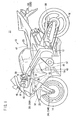
- the embodiment of the present invention will be illustrated as being applied to a full cowling type motorcycle 11 (saddle riding type vehicle) as shown in Fig. 1 .
- the embodiment is nonetheless only illustrative and is applicable to a saddle riding type vehicle of a different type (for example, a scooter, a buggy, or the like).
- a pair of left and right mechanisms or elements symmetrically disposed on a body of the motorcycle 11 will be identified by reference numerals appended with "L” for the left one and "R” for the right one.
- "right” refers to the right-hand side of the vehicle body as viewed from a rider of the motorcycle 11
- “left” refers to the left-hand side of the vehicle body as viewed from the rider.
- the motorcycle 11 includes a vehicle body frame 12, a front wheel 14, a rear wheel 16, a handlebar 18, and a seat 20.
- the vehicle body frame 12 is a cradle type constituting a vehicle body.
- the front wheel 14 is a steered wheel and a driven wheel.
- the rear wheel 16 is a driving wheel.
- the handlebar 18 steers the front wheel 14.
- the seat 20 is where a rider is seated.
- a top bridge 26 is connected to the handlebar 18 at the front of the vehicle body.
- Front forks 24L, 24R are connected to left and right ends of the top bridge 26.
- the front forks 24L, 24R penetrate through a bottom bridge 28 to journal the front wheel 14 rotatably.
- the rider sitting in the seat 20 turns the handlebar 18 to the left or right to rotate the handlebar 18, the top bridge 26, the front forks 24L, 24R, the bottom bridge 28, and the front wheel 14 integrally to the left or right around a head pipe 22.
- a front fender 25 covering the front wheel 14 from an upward direction is mounted on the front forks 24L, 24R.
- Winkers 30L, 30R are disposed at a forward side of a cowl 38 in the motorcycle 11 and winkers 32L, 32R are disposed at a rear portion side of the motorcycle 11.
- the rear wheel 16 is driven via a transmission 42 from an engine 40.
- a clutch 44 (see Fig. 5 ), which connects or disconnects a driving force from the engine 40 relative to the rear wheel 16, is disposed in juxtaposition with the transmission 42.
- An actuator unit 45 automatically causing the clutch 44 to engage or disengage is disposed near the clutch 44.
- a controller 47 performing electric control of the motorcycle 11 is disposed downwardly of the seat 20.
- the left hand side of the handlebar 18 includes a clutch lever 46 and a clutch lever sensor (lever operation amount detection means) 48 disposed thereon.
- the clutch lever 46 manually engages or disengages the clutch 44.
- the clutch lever sensor 48 detects an operation amount C of the clutch lever 46.
- the clutch lever sensor 48 may be a switch (lever operation amount detection means) like a brake switch disposed on a brake lever for lighting up a brake lamp.
- a steering angle sensor (steering angle detection means) 50 is disposed at a center of the bottom bridge 28.
- the steering angle sensor 50 detects a steering angle ⁇ of the handlebar 18 of the motorcycle 11.
- An inclination angle sensor (inclination angle detection means) 52 and an acceleration sensor 54 are disposed inside the cowl 38.
- the inclination angle sensor 52 detects an inclination angle ⁇ of the motorcycle 11 to the left or right (specifically, a bank angle).
- the acceleration sensor 54 detects an acceleration G in a longitudinal direction of the motorcycle 11.
- a rear wheel speed sensor (driving wheel speed detection means) 56 is disposed near the rear wheel 16.
- the rear wheel speed sensor 56 detects a rear wheel speed Pr.
- a front wheel speed sensor (driven wheel speed detection means) 58 detecting a front wheel speed Pf is disposed near the front wheel 14.
- the rear wheel speed sensor 56 and the front wheel speed sensor 58 are also used in an ABS (anti-lock brake system) not shown.
- the rear wheel speed Pr and the front wheel speed Pf are actually used by being multiplied by a constant in the controller 47 such that each represents a peripheral speed (a speed of the wheel in contact with a road surface) of the rear wheel 16 and the front wheel 14, respectively (driving wheel speed detection means, driven wheel speed detection means).
- the peripheral speeds are simply referred to as the rear wheel speed Pr and the front wheel speed Pf.
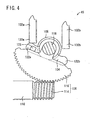
- the actuator unit 45 includes a first master cylinder 100a, a second slave cylinder 100b, a cam body 104, a gear mechanism 106, a potentiometer 108, and a control motor (actuator) 110.
- the first master cylinder 100a is connected to a first duct 60a.
- the second slave cylinder 100b is connected to a second duct 60b.
- the cam body 104 presses to drive lower ends of a first master piston 102a of the first master cylinder 100a and a second slave piston 102b.
- the gear mechanism 106 tiltably drives the cam body 104.
- the potentiometer 108 detects a tilted angle of the cam body 104.
- the control motor 110 rotatably drives the gear mechanism 106.
- the gear mechanism 106 is housed in a case 112.
- the first master cylinder 100a and the second slave cylinder 100b protrude upwardly from the case 112, being disposed in juxtaposition with each other.
- the control motor 110 protrudes sideways from a lower portion of the case 112.
- the potentiometer 108 and the control motor 110 are connected to the controller 47.
- the gear mechanism 106 includes a worm gear 114, a sector wheel gear 116, and a gear shaft 118.
- the worm gear 114 is integrally formed with a rotation shaft of the control motor 110.
- the wheel gear 116 meshes with the worm gear 114.
- the gear shaft 118 serves as a rotation shaft of the wheel gear 116.
- the cam body 104 is a symmetrically shaped cam rotatably journaled on the gear shaft 118.
- the cam body 104 includes a first cam 122a and a second cam 122b.
- the first cam 122a is disposed at a leading end of an arm extending along a first end (on the side of the first cam 122a) of the gear shaft 118.
- the second cam 122b is disposed at a leading end of an arm extending along a second end of the gear shaft 118.
- the first cam 122a and the second cam 122b may be a roller body.
- the arm extending along the first end of the cam body 104 includes a protrusion 123 disposed on a side surface thereof.
- the wheel gear 116 meshes with teeth on an upper surface side of the worm gear 114 to make a tiltable rotation in a perpendicular plane. Rotating in a clockwise direction in Fig. 2 , the wheel gear 116 brings an end thereof into abutment on the protrusion 123 of the cam body 104, thus rotating the cam body 104 in the clockwise direction.
- the first master cylinder 100a includes the first master piston 102a, a cylinder tube 124a, a first port 126a, a spring 127a, and two hydraulic oil replenishment ports 128a.
- the first master piston 102a advances into, and retracts from, the cylinder tube 124a.
- the first port 126a is disposed at an upper leading end of the first master cylinder 100a.
- the spring 127a is disposed inside the cylinder tube 124a.
- the hydraulic oil replenishment ports 128a are connected to a reservoir tank 129 (see Fig. 9) .
- the first master piston 102a includes a rod 130a, an upper primary flange 132a, and a lower secondary flange 134a. Specifically, the rod 130a protrudes into the case 112 to be in contact with, or spaced away from, the first cam 122a. The primary flange 132a and the secondary flange 134a slide along an inner peripheral surface of the cylinder tube 124a. The first master piston 102a is pushed up by the first cam 122a to displace the hydraulic oil in the first duct 60a. A pressure sensor 130 is connected sideways relative to the cylinder tube 124a.
- the two hydraulic oil replenishment ports 128a are disposed at vertical positions near the primary flange 132a in a reference position (at a bottom dead center position) in a side surface of the cylinder tube 124a.
- the hydraulic oil replenishment ports 128a are connected to the reservoir tank 129. This arrangement allows the hydraulic oil to be supplied from the reservoir tank 129 or recovered as necessary to cope with changing amounts of hydraulic oil supplied in accordance with changes in the volume of the hydraulic oil caused by changes in temperature or the like.
- the hydraulic oil replenishment ports 128a are plugged by a primary cup 136a. This leaves the first duct 60a and the reservoir tank 129 out of fluid communication from each other. Thereafter, the hydraulic oil is pressurized and displaced into the first duct 60a.
- the second slave cylinder 100b is a 90° elbow having a second port 126b connected to the second duct 60b.
- the second slave piston 102b has no portion that corresponds to the secondary flange 134a in the first master piston 102a.
- the second slave piston 102b can advance downwardly to push down the second cam 122b.
- a primary flange 132b has a bottom surface supported by a spring 127b.
- the second slave piston 102b maintains an adequate height in an initial state thereof.
- the first duct 60a can be supplied with the hydraulic oil by supplying the hydraulic oil from the second duct 60b or rotating the control motor 110.
- the clutch control system 10 includes the clutch 44, the actuator unit 45, the clutch lever 46, and the controller 47.
- the first duct 60a having communication with the first port 126a of the actuator unit 45 is connected to a first slave cylinder 140.
- the second duct 60b having communication with the second port 126b of the actuator unit 45 is connected to a cylinder chamber (second master cylinder) 46a of the clutch lever 46.
- the first slave cylinder 140 being supplied with the hydraulic oil from the first duct 60a, is capable of performing engagement and disengagement operations of the clutch 44 via a push rod 142. Specifically, the first slave cylinder 140 advances the push rod 142 to disengage the clutch 44 and retracts the push rod 142 to engage the clutch 44.
- the controller 47 drives the control motor 110 by referring to a signal from the potentiometer 108.
- the controller 47 is connected to the clutch lever sensor 48, the steering angle sensor 50, the inclination angle sensor 52, the acceleration sensor 54, the front wheel speed sensor 58, the rear wheel speed sensor 56, the potentiometer 108, and the pressure sensor 130, so that the controller 47 can receive detection signals from the foregoing elements.
- the controller 47 includes an actuator control portion 150 and an engine control portion 152.
- the actuator control portion 150 controls the control motor 110 based on the signal obtained from each of the foregoing sensors.
- the engine control portion 152 controls an output of the engine 40 based on the signal obtained from each of the foregoing sensors. In controlling the output of the engine 40, the engine control portion 152 adjusts ignition timing, a fuel injection amount, fuel injection timing, and the like, while taking into consideration signals indicating a throttle opening, an engine speed, a throttle duct vacuum, and the like.
- Fig. 7 Operations of the clutch control system 10 of the motorcycle 11 having the arrangements as described heretofore will be described with reference to Fig. 7 .
- the operations shown in Fig. 7 are realized by the controller 47 when a computer therein reads and executes a program, repeatedly executed at every brief period of time.
- step S1 of Fig. 7 signals are read from the sensors.
- step S2 it is determined whether the motorcycle 11 is in a running state or not. If it is determined that the motorcycle 11 is in the running state, the operation proceeds to step S3. If it is determined that the motorcycle 11 is in a stationary state, the current operation shown in Fig. 7 is terminated. It may be determined whether the motorcycle 11 is in the running state or not based on the front wheel speed Pf and the rear wheel speed Pr.
- step S3 it is determined whether the following conditions are met; specifically, that the rear wheel speed Pr is lower than the front wheel speed Pf (the rear wheel speed Pr is smaller than the front wheel speed Pf) and that an absolute value of a difference between the rear wheel speed Pr and the front wheel speed Pf is greater than a threshold value (a first threshold value) P1. More specifically, it is determined whether the inequality of Pr ⁇ Pf and P1 ⁇
- step S4 the operation amount C of the clutch 44 obtained from the clutch lever sensor 48 and a threshold value (a third threshold value) C1 are referred to. If C ⁇ C1, then the operation proceeds to step S5. If C ⁇ C1, then the operation proceeds to step S6.
- step S5 the control motor 110 is driven to displace an adequate amount of hydraulic oil into the first duct 60a.
- a transmission force of the clutch 44 is thereby weakened to make the clutch 44 partially engaged or disengaged, so that a driving force transmitted from the clutch 44 to the rear wheel 16 is reduced.
- the pressure sensor 130 monitors pressure in the first duct 60a.
- the decision made based on the rear wheel speed Pr and the front wheel speed Pf allows the actual condition of the motorcycle 11 to be identified, not through estimation processing. This enables clutch control in a timely manner, so that the grip force of the rear wheel 16 can be appropriately maintained.
- step S5 the transmission force of the clutch 44 may, instead, be controlled based on the inclination angle ⁇ obtained from the inclination angle sensor 52 (e.g., a degree of partial clutch engagement is adjusted). If the inclination angle ⁇ of the motorcycle 11 is fairly large, it can be determined that the motorcycle 11 is turning. Then, the clutch 44 is controlled appropriately according to the turning and the grip force of the rear wheel 16 can be maintained even more appropriately.
- Control of the transmission force of the clutch 44 based on the inclination angle ⁇ obtained from the inclination angle sensor 52 may not have to be performed with timing of step S5 (when P1 > Pr - Pf and C ⁇ C1 are true).
- the control may, instead, be performed under a predetermined condition (e.g., a condition based on the acceleration G).
- step S6 the control motor 110 is driven to bring the wheel gear 116 back to the reference position (the condition shown in Fig. 2 ), thereby terminating the operation of reducing the transmission force of the clutch 44 (specifically, the operation of step S5). If the operation of reducing the transmission force of the clutch 44 is yet to be performed, the operation is not to be started as long as the condition of step S4 is not met even with the condition of step S3 met thereafter.
- steps S4 and S6 may be omitted depending on design requirements involved and the operation of step S5 may be executed when the conditions of step S3 are met.
- step S7 it is determined whether the following conditions are met; specifically, that the rear wheel speed Pr is higher than the front wheel speed Pf (the rear wheel speed Pr is greater than the front wheel speed Pf) and that the absolute value of the difference between the rear wheel speed Pr and the front wheel speed Pf is greater than a threshold value (a second threshold value) P2. More specifically, it is determined whether the inequality of Pr > Pf and P2 ⁇
- step S8 the engine control portion 152 reduces the output of the engine 40 down to an appropriate amount.
- the rear wheel speed Pr is greater than the front wheel speed Pf by a predetermined degree or more, it can be determined that the driving force of the rear wheel 16 is not sufficiently transmitted to the road surface (e.g., the rear wheel 16 runs idle). The output of the engine 40 is then reduced so as to recover the grip force of the rear wheel 16.
- the degree of reduction in the output of the engine 40 may be adjusted based on the inclination angle ⁇ obtained from the inclination angle sensor 52. As such, when the inclination angle ⁇ of the motorcycle 11 is fairly large, it can be determined that the motorcycle 11 is turning. Then, the output of the engine 40 is controlled appropriately according to the turning and the grip force of the rear wheel 16 can be maintained even more appropriately.
- Control to adjust the degree of reduction in the output of the engine 40 based on the inclination angle ⁇ obtained from the inclination angle sensor 52 may not have to be performed with timing of step S8 (when P2 ⁇ Pr - Pf is true).
- the control may, instead, be performed under a predetermined condition (e.g., a condition based on the acceleration G).
- the inclination angle ⁇ may not have to be obtained from the inclination angle sensor 52. Rather, the clutch control system 10 may include a lateral direction acceleration sensor, or the inclination angle ⁇ may be obtained through calculation using the running speed, the steering angle ⁇ , and the like (inclination angle detection means).
- the decision made based on the rear wheel speed Pr and the front wheel speed Pf identifies the actual condition of the motorcycle 11 and controls the clutch 44 in a timely manner to maintain the grip force of the rear wheel 16 appropriately.
Landscapes
- Engineering & Computer Science (AREA)
- Mechanical Engineering (AREA)
- Chemical & Material Sciences (AREA)
- Combustion & Propulsion (AREA)
- Transportation (AREA)
- Physics & Mathematics (AREA)
- Fluid Mechanics (AREA)
- General Engineering & Computer Science (AREA)
- Automation & Control Theory (AREA)
- Hydraulic Clutches, Magnetic Clutches, Fluid Clutches, And Fluid Joints (AREA)
- One-Way And Automatic Clutches, And Combinations Of Different Clutches (AREA)
- Control Of Vehicle Engines Or Engines For Specific Uses (AREA)
Applications Claiming Priority (1)
| Application Number | Priority Date | Filing Date | Title |
|---|---|---|---|
| JP2007251325A JP5189337B2 (ja) | 2007-09-27 | 2007-09-27 | 鞍乗型車両のクラッチ制御システム |
Publications (2)
| Publication Number | Publication Date |
|---|---|
| EP2042768A1 EP2042768A1 (en) | 2009-04-01 |
| EP2042768B1 true EP2042768B1 (en) | 2010-10-13 |
Family
ID=39869684
Family Applications (1)
| Application Number | Title | Priority Date | Filing Date |
|---|---|---|---|
| EP08161233A Ceased EP2042768B1 (en) | 2007-09-27 | 2008-07-28 | Clutch control system for saddle riding type vehicle |
Country Status (5)
| Country | Link |
|---|---|
| US (1) | US8147381B2 (enExample) |
| EP (1) | EP2042768B1 (enExample) |
| JP (1) | JP5189337B2 (enExample) |
| CN (1) | CN101398045B (enExample) |
| DE (1) | DE602008002979D1 (enExample) |
Families Citing this family (18)
| Publication number | Priority date | Publication date | Assignee | Title |
|---|---|---|---|---|
| JP5200272B2 (ja) * | 2008-05-27 | 2013-06-05 | 本田技研工業株式会社 | クラッチ制御装置 |
| JP5620671B2 (ja) * | 2009-11-24 | 2014-11-05 | ヤマハ発動機株式会社 | 変速装置 |
| US9346510B2 (en) | 2011-07-28 | 2016-05-24 | Yamaha Hatsudoki Kabushiki Kaisha | Attitude controller and saddle riding type vehicle having the same |
| JP2014034964A (ja) * | 2012-08-10 | 2014-02-24 | Yamaha Motor Co Ltd | 車両 |
| JP6140569B2 (ja) * | 2013-08-08 | 2017-05-31 | 本田技研工業株式会社 | 鞍乗り型車両 |
| DE102013220164A1 (de) * | 2013-10-07 | 2015-04-23 | Robert Bosch Gmbh | Optional elektrisch betätigbares Kupplungssystem für ein Kraftfahrzeug |
| US10545048B2 (en) | 2015-07-23 | 2020-01-28 | Cardinal Health Commercial Technologies, Llc | Medication dispensing device and methods |
| WO2017082239A1 (ja) * | 2015-11-09 | 2017-05-18 | ヤマハ発動機株式会社 | リーン車両 |
| US10723334B2 (en) | 2017-03-28 | 2020-07-28 | Polaris Industries Inc. | Anti-lock brake system for all-terrain vehicle |
| MX2020005177A (es) | 2017-11-22 | 2020-08-20 | Polaris Inc | Sistema antibloqueo de frenado conmutable para vehiculo utilitario. |
| JP7064874B2 (ja) * | 2017-12-28 | 2022-05-11 | 本田技研工業株式会社 | クラッチ制御装置およびクラッチ制御システム |
| JP2019120964A (ja) | 2017-12-28 | 2019-07-22 | 本田技研工業株式会社 | レバー装置 |
| US11618422B2 (en) | 2018-11-14 | 2023-04-04 | Polaris Industries Inc. | Operating modes using a braking system for an all terrain vehicle |
| CA3098862C (en) | 2018-05-02 | 2025-10-07 | Polaris Industries Inc. | OPERATING MODES USING A BRAKING SYSTEM FOR AN ALL-TERRAIN VEHICLE |
| DE112019003302T5 (de) * | 2018-06-29 | 2021-03-18 | Honda Motor Co., Ltd. | Kupplungssteuervorrichtung für ein Fahrzeug des Sattelsitztyps |
| JP6738400B2 (ja) * | 2018-12-12 | 2020-08-12 | ブリヂストンサイクル株式会社 | 電動機付自転車 |
| TWI865481B (zh) * | 2019-01-30 | 2024-12-11 | 日商京洛股份有限公司 | 成型裝置、以及成型品的製造系統 |
| CN119084482A (zh) * | 2024-10-15 | 2024-12-06 | 上海科拉骑科技有限公司 | 跨骑式摩托车的手动多片式离合系统 |
Family Cites Families (20)
| Publication number | Priority date | Publication date | Assignee | Title |
|---|---|---|---|---|
| JPS59202963A (ja) * | 1983-04-30 | 1984-11-16 | Nec Home Electronics Ltd | スキツドコントロ−ル装置 |
| DE3528389C2 (de) * | 1985-08-07 | 2002-08-14 | Zf Sachs Ag | Anordnung zur Regelung des Antriebsschlupfs eines Kraftfahrzeugs |
| US4984161A (en) * | 1987-03-24 | 1991-01-08 | Honda Giken Kogyo Kabushiki Kaisha | Method for controlling automatic transmissions |
| JP2851277B2 (ja) * | 1987-12-11 | 1999-01-27 | 本田技研工業株式会社 | 車輌用無段変速機の制御方法 |
| US5020622A (en) * | 1988-08-17 | 1991-06-04 | Ford Motor Company | Multiple feedback loop control method and system for controlling wheel slip |
| JP3116185B2 (ja) * | 1992-01-07 | 2000-12-11 | 本田技研工業株式会社 | クラッチ操作装置 |
| DE4427040C2 (de) * | 1994-07-29 | 1998-05-20 | Steyr Daimler Puch Ag | Verfahren zur Steuerung einer als Differentialsperre wirkenden Sperrkupplung |
| DE19635809A1 (de) * | 1996-09-04 | 1998-03-05 | Bayerische Motoren Werke Ag | Verfahren und Vorrichtung zur Verbesserung der Fahrstabilität im Schubbetrieb |
| DE10236292A1 (de) * | 2001-08-16 | 2003-02-27 | Luk Lamellen & Kupplungsbau | Verfahren zum Regeln einer automatisierten Kupplung eines Kraftfahrzeuges |
| JP2003294062A (ja) * | 2002-04-03 | 2003-10-15 | Yamaha Motor Co Ltd | 自動二輪車のエンジンブレーキ制御装置 |
| EP1531279A1 (de) | 2003-11-11 | 2005-05-18 | Uwe Eisenbeis | Vorrichtung zur definierten Schlupferzeugung an Motorradschaltkupplungen |
| DE102005006556A1 (de) * | 2004-02-17 | 2005-09-08 | Volkswagen Ag | Verfahren zur Betätigung mindestens zweier parallel im Antriebsstrang eines Kraftfahrzeugs drehmomentübertragenden Kupplungen und Getriebesteuerung |
| JP4381246B2 (ja) * | 2004-07-21 | 2009-12-09 | 本田技研工業株式会社 | 車載内燃機関の制御装置 |
| DE102005035882A1 (de) | 2004-08-19 | 2006-02-23 | Luk Lamellen Und Kupplungsbau Beteiligungs Kg | Verfahren und Vorrichtung zum Regeln der Fahrstabilität eines Kraftfahrzeugs |
| DE102005003981B4 (de) * | 2005-01-28 | 2012-03-29 | Bayerische Motoren Werke Aktiengesellschaft | Verfahren zur Antriebsmomentregelung bei einem einspurigen Kraftfahrzeug |
| DE102005012775B4 (de) * | 2005-03-19 | 2016-02-25 | Bayerische Motoren Werke Aktiengesellschaft | Vorrichtung zur Erhöhung der Fahrsicherheit bei einem einspurigen Kraftfahrzeug |
| JP2006274869A (ja) * | 2005-03-29 | 2006-10-12 | Yamaha Motor Co Ltd | 鞍乗り型輸送機器用操縦制御装置 |
| RU2400383C2 (ru) * | 2005-09-08 | 2010-09-27 | Вольво Ластвагнар Аб | Избирательная антиблокировочная тормозная система |
| JP4693790B2 (ja) * | 2007-01-09 | 2011-06-01 | ヤマハ発動機株式会社 | 自動二輪車、その制御装置および制御方法、並びに自動二輪車のスリップ量検出装置およびスリップ量検出方法 |
| DE102007051064B4 (de) * | 2007-10-17 | 2010-02-11 | Getrag Getriebe- Und Zahnradfabrik Hermann Hagenmeyer Gmbh & Cie Kg | Fehlererkennungsverfahren für automatisierte Kraftfahrzeuggetriebe |
-
2007
- 2007-09-27 JP JP2007251325A patent/JP5189337B2/ja active Active
-
2008
- 2008-07-28 DE DE602008002979T patent/DE602008002979D1/de active Active
- 2008-07-28 EP EP08161233A patent/EP2042768B1/en not_active Ceased
- 2008-09-03 CN CN2008102148493A patent/CN101398045B/zh not_active Expired - Fee Related
- 2008-09-25 US US12/238,231 patent/US8147381B2/en not_active Expired - Fee Related
Also Published As
| Publication number | Publication date |
|---|---|
| JP5189337B2 (ja) | 2013-04-24 |
| EP2042768A1 (en) | 2009-04-01 |
| US20090088298A1 (en) | 2009-04-02 |
| US8147381B2 (en) | 2012-04-03 |
| CN101398045B (zh) | 2011-10-05 |
| JP2009079749A (ja) | 2009-04-16 |
| CN101398045A (zh) | 2009-04-01 |
| DE602008002979D1 (de) | 2010-11-25 |
Similar Documents
| Publication | Publication Date | Title |
|---|---|---|
| EP2042768B1 (en) | Clutch control system for saddle riding type vehicle | |
| US9181917B2 (en) | Start control system and vehicle | |
| JP5730636B2 (ja) | トラクション制御装置 | |
| JP5121159B2 (ja) | 自動変速制御装置および車両 | |
| US12577989B2 (en) | Clutch control apparatus | |
| US11994180B1 (en) | Clutch control device | |
| JP5247313B2 (ja) | 制御システムおよび車両 | |
| JP4873542B2 (ja) | 自動変速制御装置および車両 | |
| JP7112594B2 (ja) | クラッチ制御装置 | |
| JP5107184B2 (ja) | 制御システムおよび車両 | |
| US20240313673A1 (en) | Clutch control apparatus | |
| WO2022209634A1 (ja) | クラッチ制御装置 | |
| EP2048401B1 (en) | Gear change process for an automated manual transmission unit and automated transmission for a vehicle | |
| JP4478006B2 (ja) | エンジンの制御装置、エンジンの制御方法及び鞍乗型車両 | |
| EP1826087B1 (en) | Automatic gear shift device and method for a vehicle | |
| EP1826442B1 (en) | Automatic transmission control method and automatic transmission controller | |
| CN121079516A (zh) | 离合器控制装置 | |
| CN115891960A (zh) | 离合器控制装置 | |
| JP4873543B2 (ja) | 自動変速制御装置および車両 | |
| US12179735B2 (en) | Clutch control device | |
| JP4911995B2 (ja) | 自動二輪車 | |
| EP4160041A1 (en) | Clutch control device |
Legal Events
| Date | Code | Title | Description |
|---|---|---|---|
| PUAI | Public reference made under article 153(3) epc to a published international application that has entered the european phase |
Free format text: ORIGINAL CODE: 0009012 |
|
| 17P | Request for examination filed |
Effective date: 20080728 |
|
| AK | Designated contracting states |
Kind code of ref document: A1 Designated state(s): AT BE BG CH CY CZ DE DK EE ES FI FR GB GR HR HU IE IS IT LI LT LU LV MC MT NL NO PL PT RO SE SI SK TR |
|
| AX | Request for extension of the european patent |
Extension state: AL BA MK RS |
|
| AKX | Designation fees paid |
Designated state(s): DE FR IT |
|
| GRAP | Despatch of communication of intention to grant a patent |
Free format text: ORIGINAL CODE: EPIDOSNIGR1 |
|
| GRAS | Grant fee paid |
Free format text: ORIGINAL CODE: EPIDOSNIGR3 |
|
| GRAA | (expected) grant |
Free format text: ORIGINAL CODE: 0009210 |
|
| AK | Designated contracting states |
Kind code of ref document: B1 Designated state(s): DE FR IT |
|
| REF | Corresponds to: |
Ref document number: 602008002979 Country of ref document: DE Date of ref document: 20101125 Kind code of ref document: P |
|
| PLBE | No opposition filed within time limit |
Free format text: ORIGINAL CODE: 0009261 |
|
| STAA | Information on the status of an ep patent application or granted ep patent |
Free format text: STATUS: NO OPPOSITION FILED WITHIN TIME LIMIT |
|
| 26N | No opposition filed |
Effective date: 20110714 |
|
| REG | Reference to a national code |
Ref country code: DE Ref legal event code: R097 Ref document number: 602008002979 Country of ref document: DE Effective date: 20110714 |
|
| REG | Reference to a national code |
Ref country code: DE Ref legal event code: R084 Ref document number: 602008002979 Country of ref document: DE Effective date: 20140430 |
|
| REG | Reference to a national code |
Ref country code: FR Ref legal event code: PLFP Year of fee payment: 9 |
|
| REG | Reference to a national code |
Ref country code: FR Ref legal event code: PLFP Year of fee payment: 10 |
|
| REG | Reference to a national code |
Ref country code: FR Ref legal event code: PLFP Year of fee payment: 11 |
|
| PGFP | Annual fee paid to national office [announced via postgrant information from national office to epo] |
Ref country code: FR Payment date: 20180612 Year of fee payment: 11 |
|
| PG25 | Lapsed in a contracting state [announced via postgrant information from national office to epo] |
Ref country code: FR Free format text: LAPSE BECAUSE OF NON-PAYMENT OF DUE FEES Effective date: 20190731 |
|
| PGFP | Annual fee paid to national office [announced via postgrant information from national office to epo] |
Ref country code: IT Payment date: 20210610 Year of fee payment: 14 |
|
| PGFP | Annual fee paid to national office [announced via postgrant information from national office to epo] |
Ref country code: DE Payment date: 20210629 Year of fee payment: 14 |
|
| REG | Reference to a national code |
Ref country code: DE Ref legal event code: R119 Ref document number: 602008002979 Country of ref document: DE |
|
| PG25 | Lapsed in a contracting state [announced via postgrant information from national office to epo] |
Ref country code: DE Free format text: LAPSE BECAUSE OF NON-PAYMENT OF DUE FEES Effective date: 20230201 |
|
| PG25 | Lapsed in a contracting state [announced via postgrant information from national office to epo] |
Ref country code: IT Free format text: LAPSE BECAUSE OF NON-PAYMENT OF DUE FEES Effective date: 20220728 |