EP2037992B1 - Vorrichtung zur dosierten abgabe von versprühbaren stoffen - Google Patents
Vorrichtung zur dosierten abgabe von versprühbaren stoffen Download PDFInfo
- Publication number
- EP2037992B1 EP2037992B1 EP07785941A EP07785941A EP2037992B1 EP 2037992 B1 EP2037992 B1 EP 2037992B1 EP 07785941 A EP07785941 A EP 07785941A EP 07785941 A EP07785941 A EP 07785941A EP 2037992 B1 EP2037992 B1 EP 2037992B1
- Authority
- EP
- European Patent Office
- Prior art keywords
- housing part
- valve
- switch
- container
- sprayable
- Prior art date
- Legal status (The legal status is an assumption and is not a legal conclusion. Google has not performed a legal analysis and makes no representation as to the accuracy of the status listed.)
- Not-in-force
Links
- 239000000126 substance Substances 0.000 title claims abstract description 59
- 239000000443 aerosol Substances 0.000 claims abstract description 5
- 239000003814 drug Substances 0.000 claims description 11
- 230000003287 optical effect Effects 0.000 claims description 4
- 238000013500 data storage Methods 0.000 claims 1
- 238000012384 transportation and delivery Methods 0.000 description 14
- 239000007921 spray Substances 0.000 description 5
- 238000004140 cleaning Methods 0.000 description 4
- 229940079593 drug Drugs 0.000 description 4
- 201000010099 disease Diseases 0.000 description 3
- 208000037265 diseases, disorders, signs and symptoms Diseases 0.000 description 3
- 239000007788 liquid Substances 0.000 description 3
- 239000000203 mixture Substances 0.000 description 3
- 229920003023 plastic Polymers 0.000 description 3
- 230000000007 visual effect Effects 0.000 description 3
- 230000006870 function Effects 0.000 description 2
- 239000012780 transparent material Substances 0.000 description 2
- 206010020751 Hypersensitivity Diseases 0.000 description 1
- 239000013543 active substance Substances 0.000 description 1
- 230000007815 allergy Effects 0.000 description 1
- 208000006673 asthma Diseases 0.000 description 1
- 230000005540 biological transmission Effects 0.000 description 1
- 238000001514 detection method Methods 0.000 description 1
- 238000005553 drilling Methods 0.000 description 1
- 238000002347 injection Methods 0.000 description 1
- 239000007924 injection Substances 0.000 description 1
- 239000002184 metal Substances 0.000 description 1
- 239000000843 powder Substances 0.000 description 1
- 210000002345 respiratory system Anatomy 0.000 description 1
- 239000007787 solid Substances 0.000 description 1
- 239000000243 solution Substances 0.000 description 1
- XLYOFNOQVPJJNP-UHFFFAOYSA-N water Substances O XLYOFNOQVPJJNP-UHFFFAOYSA-N 0.000 description 1
Images


Classifications
-
- A—HUMAN NECESSITIES
- A61—MEDICAL OR VETERINARY SCIENCE; HYGIENE
- A61M—DEVICES FOR INTRODUCING MEDIA INTO, OR ONTO, THE BODY; DEVICES FOR TRANSDUCING BODY MEDIA OR FOR TAKING MEDIA FROM THE BODY; DEVICES FOR PRODUCING OR ENDING SLEEP OR STUPOR
- A61M15/00—Inhalators
- A61M15/009—Inhalators using medicine packages with incorporated spraying means, e.g. aerosol cans
-
- A—HUMAN NECESSITIES
- A61—MEDICAL OR VETERINARY SCIENCE; HYGIENE
- A61M—DEVICES FOR INTRODUCING MEDIA INTO, OR ONTO, THE BODY; DEVICES FOR TRANSDUCING BODY MEDIA OR FOR TAKING MEDIA FROM THE BODY; DEVICES FOR PRODUCING OR ENDING SLEEP OR STUPOR
- A61M15/00—Inhalators
- A61M15/0065—Inhalators with dosage or measuring devices
- A61M15/0068—Indicating or counting the number of dispensed doses or of remaining doses
- A61M15/008—Electronic counters
-
- A—HUMAN NECESSITIES
- A61—MEDICAL OR VETERINARY SCIENCE; HYGIENE
- A61M—DEVICES FOR INTRODUCING MEDIA INTO, OR ONTO, THE BODY; DEVICES FOR TRANSDUCING BODY MEDIA OR FOR TAKING MEDIA FROM THE BODY; DEVICES FOR PRODUCING OR ENDING SLEEP OR STUPOR
- A61M2205/00—General characteristics of the apparatus
- A61M2205/58—Means for facilitating use, e.g. by people with impaired vision
- A61M2205/581—Means for facilitating use, e.g. by people with impaired vision by audible feedback
Definitions
- the present invention relates to a device for the metered dispensing of sprayable substances, in particular of aerosols, with an electronic device for detecting the charges, and with a first housing part, which forms a receptacle for a container containing the sprayable substance containing a valve.
- Such devices for metered delivery of sprayable substances can be designed in particular as inhalers and used in medicine for the treatment of diseases.
- inhalers are suitable for example for the treatment of asthma, allergies or other diseases and are used in particular for the metered administration of a medicament which is absorbed via the mouth or nose.
- metered aerosols In this context, one speaks of so-called metered aerosols.
- Devices for the metered delivery of medicaments are known in different embodiments. That's how it shows EP 0 448 204 B1
- a device with a one-piece housing, in which a receptacle for a sprayable substance receiving container is provided.
- the housing has a hollow mouthpiece arranged at an angle to the container longitudinal axis, via which the sprayable substance can be dispensed and inhaled upon actuation of a valve provided on the container.
- the dispensing of the sprayable substance takes place in that the container moves towards the housing and thereby the valve provided on the container is actuated.
- the known device is provided with an electronic device having a switch which bears directly on the container and is actuated by the latter.
- Another inhaler is in the EP 0 775 499 B1 described.
- a device is arranged on the upper end of the housing, which should indicate the number of dispensed metered quantities.
- the number of discharges is determined by a sensor that measures the pressure surge in the connecting channel of the mouthpiece.
- the US 5,411,173 describes an electronic counting device for a spray device with which the number of deliveries is detected and can be displayed on a display.
- the previously known device can be attached by means of a clip on the side wall of the sprayer housing.
- the counter is actuated by a handle, which is kept movable.
- a foot portion may be provided, which rests against the underside of the container receiving the liquid.
- the invention has the object to provide a device which is easy to use and reliably determines the number and / or duration of deliveries of the sprayable substance.
- the device according to the invention is advantageous.
- the detection of the delivery of the sprayable substance is independent of the container, since the switch is actuated by the relative movement of the first and second housing part. Therefore, the device can also function independently of the exact shape and / or size of the particular container used, so that one and the same device can be used in conjunction with various containers. In this case, the delivery of the sprayable medium can always be reliably detected.
- the sprayable substance may preferably be present as a liquid or a powder.
- the sprayable substance may also comprise a solution and / or a mixture of different substances.
- the sprayable substance may be a therapeutically active composition, such as a drug.
- first and the second housing part are connected in particular via a bayonet closure such that the first and second housing part can occupy each other a working position and a release position, wherein in the working position, the first and second housing part relative to each other in the axial direction movable are and wherein in the release position, the second housing part of the first housing part is removable.
- the two housing parts in the working position, can be moved towards each other to actuate the valve of the container.
- the second housing part may e.g. be removed for cleaning.
- the switch is a mechanical switch, a proximity switch, a magnetic switch, and / or an optical switch.
- an electrical signal is generated, which makes it possible to detect the delivery of the sprayable medium.
- a mechanical switch which opens and closes an electrical contact, is particularly inexpensive to produce and is particularly suitable for a disposable product.
- a further improvement is achieved in that the switch is not designed to rest on the container. The operation of the switch is then completely independent of the container, in particular its size or shape.
- the invention can further be provided that in the receptacle of the container, which has a container body and a container head with the valve for the metered delivery of the sprayable substance, at least partially receivable.
- the first one can do this Housing part have a hollow shaft in which the container body is wholly or partially receivable.
- the second housing part has a first section for receiving the container head and a hollow second section extending in particular at an angle to the first section. It has proven useful if the hollow second section is designed as a mouthpiece and / or nosepiece.
- the cleaning of the device is facilitated if the second housing part is removable. Then it is possible to remove this housing part after removal, e.g. separately under running water to clean.
- the number and / or the duration of the charges are recorded by the electronic device for recording the charges. If the container is one with a metering valve which emits a constant amount of the substance with each actuation, the remaining quantity remaining in the container can already be deduced from the number of actuations.
- the electronic means for detecting the charges has an electronic processing unit and an electronic data memory
- the charges detected by the switch can be counted particularly easily. From this, then the device can easily determine the remaining amount remaining in the container, if previously information about the maximum number of duties was stored.
- the electronic device for detecting the charges has a visual display, through which information about the number of charges paid and / or the number of remaining charges can be displayed.
- a visual display through which information about the number of charges paid and / or the number of remaining charges can be displayed.
- a low-cost LCD display or other display can be used.
- a further improvement is achieved in that the electronic device for detecting the charges has an acoustic signal generator.
- the user can e.g. be informed of a wrong operation. It is also conceivable to use such a signal generator to remind the user of the next time to take the substance.
- the electronic device for detecting the charges is arranged with the switch on or in the first or second housing part and the switch is actuated by a provided on the respective other housing part actuating element in a relative movement of the first and second housing part.
- the electronic device is arranged on or in the first housing part, since then the second housing part can be easily cleaned, without this affecting the electronic device.
- the device is designed as an inhalation device, in particular for a medicament.
- the sprayable substance preferably a drug or other therapeutically active composition.
- the delivery of the sprayable substance is particularly easy when the substance is taken under pressure in the container.
- the dosage is then simple and accurate when the valve of the container is designed as a metering valve which emits a constant amount of the sprayable substance in particular jerky with each actuation.
- the figures show a device for the metered delivery of sprayable substances, which is designed as an inhaler.
- liquid or solid substances can be administered in particular as aerosols via the respiratory tract.
- medicaments or other therapeutically active substances can be delivered by the device as sprayable substances.
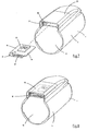
- the device shown in the figures has a first housing part 1 and second housing part 2.
- a container 3 is accommodated, which contains the sprayable substance.
- FIGS. 3 to 6a let recognize that the container 3 has a provided with a valve 5 not shown container head 6 and a container body 7.
- the container 3 is designed as a pressure vessel made of metal, in which the sprayable substance is added under pressure. Due to this overpressure, the sprayable substance can be dispensed automatically upon actuation of the valve 5.
- the valve 5 is designed as a metering valve, which delivers a constant amount of the sprayable substance as a spray when actuated. In this way, the user can simply spray the substance by or dose the valve 5 several times.
- the valve 5 has a projecting hollow valve pin 11, through which the valve 5 can be actuated. In this case, the valve 5 is held by a spring, not shown, in the closed position and can be moved by pressure on the movable valve pin 11 in the open position.
- the first housing part 1 forms a receptacle 13 for the container body 7 and has for this purpose an elongated hollow shaft 4.
- FIG. 3 indicates that the entire container body 7 is received in the cylindrical receptacle 13. In this case, the container body 7 bears against the first housing part 1.
- the first housing part 1 has at its one end a bottom portion 24 which forms with its outside a first handle portion 25. At the opposite end of the first housing part 1 is open.
- the second housing part 2 has a first section 8 for receiving the container head 6 and is movable relative to the first housing part 1 in the longitudinal direction of the valve pin 11.
- an actuating portion 12 is formed for the valve 5.
- the actuating portion 12 abuts against the valve pin 11 and receives the free end of the valve pin 11.
- a second section 9 of the second housing part 2 is hollow and aligned at an angle to the first section 8.
- the hollow second portion 9 forms a mouthpiece in the illustrated embodiment.
- the second portion 9 may be formed, for example, as a nose piece, if the delivery of the sprayable substance is to take place in the nose.
- the hollow second portion 9 is protected when not in use by a removable cap 10, such as Figures 3 and 4 can be removed.
- the second housing part 2 also has the first handle portion 25 of the first housing part 1 opposite a second, curved handle portion 26.
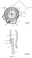
- the second housing part 2 can be removed from the first housing part 1. While the FIGS. 1 . 3 and 12 the first and second housing part 1, 2 show in their working position is in the Figures 10 and 13 a release position shown. First and second housing part 1, 2 can be rotated against each other and thereby moved from the working position to the release position. For this purpose, the first and second housing part 1, 2 are connected via a bayonet closure, which makes it possible to remove the second housing part 2 in the release position of the first housing part 1. This is especially good in the FIGS. 10 to 13 to recognize, where FIG. 12 the working position and Figures 10 and 13 represent the release position.
- first and second housing part 1, 2 can be moved in the axial direction to each other and thus the valve 5 are actuated. In the release position, this is not possible, since the housing parts stops 14, 14 ', which an axial movement towards each other only in allow the working position. As a result, unintentional triggering during assembly can be avoided.
- FIG. 12a shows an enlarged detail (section along the line EE FIG. 12 ) of the bayonet lock.
- projections 15, 15 'of the bayonet closure in the working position prevent the second housing part 2 from being removed from the first housing part 1.
- the first and second housing parts 1, 2 are designed in such a way that they can be moved towards one another for actuation of the valve 5.
- FIG. 13a illustrates how in the release position, when the first and second housing parts are rotated relative to each other as shown, the projections 15, 15 'of the bayonet lock are disengaged and allow a decrease of the second housing part 2.
- the apparatus shown in the figures comprises an electronic device 16 for detecting the discharges of the sprayable substance.
- the electronic device 16 is accommodated in a holder formed on the first housing part 1, which in the illustrated embodiment is formed by a chamber 18 with a substantially slot-shaped form.
- the chamber 18 protects the electronic device 16 from damage and tampering.
- the electronic device 16 in this case has a plate 19, which is designed as a printed circuit board or board to receive the necessary components and electrically conductive to connect with each other. Also, the switch 17 is disposed on the plate 19 and has an electrical contact, which is opened or closed upon actuation of the switch.
- the plate 19 is reliably held in the illustrated embodiment by latching means 21 in the chamber 18 (see. Fig. 9 ). The assembly is easy because the plate 19 can be prefabricated and then only has to be inserted into the chamber 18. Alternatively, the plate 19 may be poured into the chamber 18.
- the in the FIGS. 5 to 6a schematically illustrated switch 17 is actuated by an actuating portion 20 which is arranged on the second housing part 2.
- the switch 17 is arranged on the second housing part 2 facing the end portion of the first housing part 1.
- the switch 17 is not applied to the container 3. Rather, the switch 17 is arranged in the chamber 18 of the first housing part, that the switch 17 is protected and can not be operated by mistake. An abusive triggering of the switch 17 is made more difficult because the switch 17 can not be reached with a finger.
- the projecting operation portion 20 is arranged on the second housing part 2 so as to extend into the chamber 18 when the first and second housing parts 1, 2 are moved towards each other for actuating the valve 5. This position is in the Figures 6 and 6a shown while the FIGS. 5, 5a show the unactuated position.
- the electronic device 16 detects the number of discharges or actuations of the valve 5.
- the electronic device 16 on the plate 19 has a computing unit, a data memory and an energy source in the form of a battery (not shown in detail). , so that the detected by the switch 17 levies, each with a electrical contact is closed, can be counted. If the maximum number of actuations of the valve 5 (corresponding to the respective filling quantity of the container 3) is deposited in advance in the electronic device 16, the remaining quantity remaining or the remaining number of possible deliveries of the sprayable substance can be determined directly. The respective maximum number of actuations can be entered by storing the corresponding values by way of programming or by means of a coding switch or the like.
- the determined information is displayed via a small optical display 22, which is designed as an LCD display. This is visible from the outside. Accordingly, the cover 23 of the chamber 18 is made of a transparent material, in particular plastic. Alternatively or in addition to the visual display, an unillustrated acoustic signal generator can be provided.
- the electronic device 16 has a clock, further functions are possible. In this case, e.g. the user visually and / or acoustically be reminded of the next intake of his drug. Furthermore, the expiry date of the expiration date could be displayed to the user or a corresponding warning message given. A warning is also practical, as soon as a certain residual quantity of the sprayable substance is exceeded. In addition, the intake times and the respective dosages or the number of delivered sprays can be stored.
- the electronic device 16 such that the stored information can be read out via an interface. In this case, for example, can be checked when and in what dosage the respective drug was taken.
- 16 contacts 27 are provided on the device.
- a wireless data transmission can be provided.
- valve 5 is formed as a metering valve, it is not necessary to detect the duration of the actuation of the valve 5, since with each spray a respective amount of the sprayable substance is discharged.
- the device can also be designed so that it detects the duration of the dispensing of the sprayable substance and thus allows a determination of the amount dispensed in this case.
- First and second housing part 1, 2 are made of plastic as an injection molded part.
- the first housing part 1 is made of transparent plastic, so that not only the visual display 22 but also information mounted on the container 3 are visible.
- the device shown has a small number of components and is inexpensive to produce. It is therefore also suitable for single use. Single use in this sense is when the device is renewed simultaneously with the respective container. Of course, a multiple use would be possible. In this case, care must be taken, for example via a reset switch, that when the container is renewed, the electronic device 16 is reset to its original state.
Landscapes
- Health & Medical Sciences (AREA)
- Engineering & Computer Science (AREA)
- Life Sciences & Earth Sciences (AREA)
- Heart & Thoracic Surgery (AREA)
- Bioinformatics & Cheminformatics (AREA)
- Pulmonology (AREA)
- Anesthesiology (AREA)
- Biomedical Technology (AREA)
- Hematology (AREA)
- Animal Behavior & Ethology (AREA)
- General Health & Medical Sciences (AREA)
- Public Health (AREA)
- Veterinary Medicine (AREA)
- Biophysics (AREA)
- Containers And Packaging Bodies Having A Special Means To Remove Contents (AREA)
- Nozzles (AREA)
Applications Claiming Priority (2)
| Application Number | Priority Date | Filing Date | Title |
|---|---|---|---|
| DE102006032293A DE102006032293A1 (de) | 2006-07-11 | 2006-07-11 | Vorrichtung zur dosierten Abgabe von versprühbaren Stoffen |
| PCT/EP2007/006052 WO2008006527A1 (de) | 2006-07-11 | 2007-07-09 | Vorrichtung zur dosierten abgabe von versprühbaren stoffen |
Publications (2)
| Publication Number | Publication Date |
|---|---|
| EP2037992A1 EP2037992A1 (de) | 2009-03-25 |
| EP2037992B1 true EP2037992B1 (de) | 2012-01-11 |
Family
ID=38577661
Family Applications (1)
| Application Number | Title | Priority Date | Filing Date |
|---|---|---|---|
| EP07785941A Not-in-force EP2037992B1 (de) | 2006-07-11 | 2007-07-09 | Vorrichtung zur dosierten abgabe von versprühbaren stoffen |
Country Status (6)
Families Citing this family (10)
| Publication number | Priority date | Publication date | Assignee | Title |
|---|---|---|---|---|
| GB2469068B (en) * | 2009-03-31 | 2011-03-09 | Naseem Bari | Usage indicator |
| DE102010024912B4 (de) * | 2010-06-15 | 2013-02-28 | Aptar Radolfzell Gmbh | Inhalationsvorrichtung |
| NZ595367A (en) * | 2011-09-23 | 2012-02-24 | Nexus6 Ltd | A dose counting mechanism adapted to enclose a medicament delivery device |
| CN105163784B (zh) * | 2013-03-21 | 2019-07-26 | 皇家飞利浦有限公司 | 用于监控呼吸药物输送装置使用的系统和方法 |
| US10722666B2 (en) * | 2014-05-07 | 2020-07-28 | Boehringer Ingelheim International Gmbh | Nebulizer with axially movable and lockable container and indicator |
| WO2016033421A1 (en) | 2014-08-28 | 2016-03-03 | Microdose Therapeutx, Inc. | Compliance monitoring module for an inhaler |
| CN108136144B (zh) | 2015-07-20 | 2020-10-30 | 珍珠治疗公司 | 气雾剂输送系统 |
| AU201613322S (en) * | 2015-12-23 | 2016-07-12 | Adherium Nz Ltd | A Compliance Monitor for a Medicament Inhaler |
| USD882064S1 (en) * | 2016-06-23 | 2020-04-21 | Adherium (Nz) Limited | Compliance monitor for a medicament inhaler |
| EP3485930B1 (en) * | 2017-11-20 | 2021-04-14 | Presspart Gmbh & Co. Kg | Inhalation system |
Family Cites Families (30)
| Publication number | Priority date | Publication date | Assignee | Title |
|---|---|---|---|---|
| US3006340A (en) * | 1958-03-03 | 1961-10-31 | Meshberg Philip | Dispensing package |
| US3306252A (en) * | 1963-12-03 | 1967-02-28 | Johnson & Johnson | Shielded aerosol medicament dispenser |
| US3422996A (en) * | 1966-11-25 | 1969-01-21 | Valve Corp Of America | Safety actuator cap for hand-held dispensers |
| US3610480A (en) * | 1969-07-31 | 1971-10-05 | Geigy Chem Corp | Aerosol dispensing apparatus |
| US4159067A (en) * | 1977-06-06 | 1979-06-26 | Akers Edward G | Dispensing pump for container |
| NO146343C (no) * | 1979-11-07 | 1982-09-15 | Sterwin Ag | Doseindikator for anvendelse ved inhalasjon |
| FR2605606B1 (fr) * | 1986-10-23 | 1989-06-09 | Valois | Dispositif de securite et d'inviolabilite pour pulverisateur du type nasal |
| US5020527A (en) | 1990-02-20 | 1991-06-04 | Texax-Glynn Corporation | Inhaler device with counter/timer means |
| DE4027672A1 (de) * | 1990-08-31 | 1992-03-05 | Pfeiffer Erich Gmbh & Co Kg | Austragvorrichtung fuer medien |
| GB9026025D0 (en) * | 1990-11-29 | 1991-01-16 | Boehringer Ingelheim Kg | Inhalation device |
| US5450336A (en) * | 1991-03-05 | 1995-09-12 | Aradigm Corporation | Method for correcting the drift offset of a transducer |
| BR9407608A (pt) * | 1993-09-22 | 1997-01-14 | Senetics Inc | Dispositivo indicador e dispositivo para indicar a liberação de medicamento em aerossol |
| US5411173A (en) * | 1993-12-17 | 1995-05-02 | Weinstein; Albert | Counter attachment for product dispensers |
| US5564414A (en) * | 1994-05-26 | 1996-10-15 | Walker; William F. | Pressurized and metered medication dose counter on removable sleeve |
| US5622163A (en) | 1994-11-29 | 1997-04-22 | Iep Group, Inc. | Counter for fluid dispensers |
| US5676129A (en) | 1996-03-14 | 1997-10-14 | Oneida Research Services, Inc. | Dosage counter for metered dose inhaler (MDI) systems using a miniature pressure sensor |
| GB2316451B (en) * | 1996-08-15 | 2000-09-13 | Tenax Corp | Dispensing device |
| US7799337B2 (en) * | 1997-07-21 | 2010-09-21 | Levin Bruce H | Method for directed intranasal administration of a composition |
| US6113008A (en) * | 1998-08-20 | 2000-09-05 | 3M Innovative Properties Company | Actuator system for spraying a formulation onto a host |
| US6202642B1 (en) * | 1999-04-23 | 2001-03-20 | Medtrac Technologies, Inc. | Electronic monitoring medication apparatus and method |
| AR026914A1 (es) * | 1999-12-11 | 2003-03-05 | Glaxo Group Ltd | Distribuidor de medicamento |
| DE10109671C1 (de) * | 2001-02-28 | 2002-05-02 | Draeger Medical Ag | Vorrichtung zur Abgabe eines Gases an ein Beatmungsgerät |
| SE517513C2 (sv) * | 2000-09-25 | 2002-06-11 | Microdrug Ag | Gränssnittsarragemang för att säkerställa korrekt dosering samt säker funktion och hantering vid en inhalator för torrt pulver. |
| GB0026646D0 (en) * | 2000-10-31 | 2000-12-13 | Glaxo Group Ltd | Medicament dispenser |
| US6651844B2 (en) * | 2002-02-22 | 2003-11-25 | Schering Corporation | Spray dispenser counter |
| GB0204829D0 (en) * | 2002-03-01 | 2002-04-17 | Glaxo Group Ltd | A fluid dispensing device |
| JP3696184B2 (ja) * | 2002-06-24 | 2005-09-14 | 榮製機株式会社 | 再充填可能なスプレー容器 |
| DE102004006450B4 (de) * | 2004-02-05 | 2012-09-27 | Ing. Erich Pfeiffer Gmbh | Dosiervorrichtung |
| JP2007522902A (ja) * | 2004-02-24 | 2007-08-16 | ベーリンガー インゲルハイム インターナショナル ゲゼルシャフト ミット ベシュレンクテル ハフツング | ネブライザ |
| SE0401786D0 (sv) * | 2004-07-05 | 2004-07-05 | Astrazeneca Ab | Inhaler device |
-
2006
- 2006-07-11 DE DE102006032293A patent/DE102006032293A1/de not_active Withdrawn
-
2007
- 2007-07-09 JP JP2009518771A patent/JP4997287B2/ja not_active Expired - Fee Related
- 2007-07-09 WO PCT/EP2007/006052 patent/WO2008006527A1/de active Application Filing
- 2007-07-09 AT AT07785941T patent/ATE540716T1/de active
- 2007-07-09 EP EP07785941A patent/EP2037992B1/de not_active Not-in-force
-
2009
- 2009-01-08 US US12/319,656 patent/US9004062B2/en not_active Expired - Fee Related
Also Published As
| Publication number | Publication date |
|---|---|
| EP2037992A1 (de) | 2009-03-25 |
| US20090151723A1 (en) | 2009-06-18 |
| ATE540716T1 (de) | 2012-01-15 |
| JP2009542382A (ja) | 2009-12-03 |
| US9004062B2 (en) | 2015-04-14 |
| JP4997287B2 (ja) | 2012-08-08 |
| DE102006032293A1 (de) | 2008-01-24 |
| WO2008006527A1 (de) | 2008-01-17 |
Similar Documents
| Publication | Publication Date | Title |
|---|---|---|
| EP2037992B1 (de) | Vorrichtung zur dosierten abgabe von versprühbaren stoffen | |
| EP1216720B1 (de) | Vorrichtung zum Erfassen der Betätigung eines Spenders | |
| DE69826039T2 (de) | Aerosolbehälter und Spender mit Dosiereinheitenzähler | |
| EP1720662B1 (de) | Zerstuber mit einer berwachungseinrichtung zur zählung von betätigungen des zerstäubers | |
| DE69503499T2 (de) | Pulverinhalator | |
| EP0334349B1 (de) | Vorrichtung zur dosierten Verabreichung eines flüssigen Arzneimittels | |
| DE60318475T2 (de) | Abgabevorrichtung | |
| DE60121195T2 (de) | Dosierspender | |
| DE60030421T2 (de) | Abgabevorrichtung mit einer dosierzähleinrichtung | |
| DE60020715T2 (de) | Inhaliervorrichtung | |
| DE60123646T2 (de) | Sicheres verteilungsgerät | |
| DE102011007008B4 (de) | Medienspender | |
| EP0998316B1 (de) | Dosierknopfsicherung an einer vorrichtung zur dosierten verabreichung eines injizierbaren produkts | |
| DE3535561C2 (de) | Vorrichtung zum Inhalieren einer pulverförmigen medizinischen Substanz | |
| DE60115480T2 (de) | Inhalationsgerät | |
| EP1512119B1 (de) | Zahlwerk zum zahlen dosierter abgaben flüssiger, pastöser oder fester produkte sowie einrichtung zum dosierten abgeben solcher produkte | |
| DE8590143U1 (de) | Medizinische Sprühvorrichtung | |
| DE202017101591U1 (de) | Vorrichtung zur oralen oder intranasalen Verabreichung einer pharmazeutisch wirksamen Medikation | |
| EP0753293B1 (de) | Vorrichtung zur Verabreichung von Substanzen, insbesondere Inhalationspräparate | |
| EP0373237A1 (de) | Inhalationsgerät, insbesondere Taschen-Inhalationsgerät | |
| DE602004008110T2 (de) | Inhalatorkappen-gurt | |
| DE202016003139U1 (de) | Nasenapplikator | |
| DE69621149T2 (de) | Pulverinhalator | |
| DE202018002848U1 (de) | Elektronischer Inhalator | |
| WO1991002508A1 (de) | Tragbare datenerfassungsvorrichtung therapierelevanter ereignisse |
Legal Events
| Date | Code | Title | Description |
|---|---|---|---|
| PUAI | Public reference made under article 153(3) epc to a published international application that has entered the european phase |
Free format text: ORIGINAL CODE: 0009012 |
|
| 17P | Request for examination filed |
Effective date: 20090130 |
|
| AK | Designated contracting states |
Kind code of ref document: A1 Designated state(s): AT BE BG CH CY CZ DE DK EE ES FI FR GB GR HU IE IS IT LI LT LU LV MC MT NL PL PT RO SE SI SK TR |
|
| AX | Request for extension of the european patent |
Extension state: AL BA HR MK RS |
|
| RTI1 | Title (correction) |
Free format text: DEVICE FOR DOSED ADMINISTRATION OF SPRAYABLE SUBSTANCES |
|
| GRAP | Despatch of communication of intention to grant a patent |
Free format text: ORIGINAL CODE: EPIDOSNIGR1 |
|
| DAX | Request for extension of the european patent (deleted) | ||
| GRAS | Grant fee paid |
Free format text: ORIGINAL CODE: EPIDOSNIGR3 |
|
| GRAA | (expected) grant |
Free format text: ORIGINAL CODE: 0009210 |
|
| RTI1 | Title (correction) |
Free format text: DEVICE FOR DOSED ADMINISTRATION OF SPRAYABLE SUBSTANCES |
|
| AK | Designated contracting states |
Kind code of ref document: B1 Designated state(s): AT BE BG CH CY CZ DE DK EE ES FI FR GB GR HU IE IS IT LI LT LU LV MC MT NL PL PT RO SE SI SK TR |
|
| REG | Reference to a national code |
Ref country code: GB Ref legal event code: FG4D Free format text: NOT ENGLISH |
|
| REG | Reference to a national code |
Ref country code: CH Ref legal event code: EP |
|
| REG | Reference to a national code |
Ref country code: AT Ref legal event code: REF Ref document number: 540716 Country of ref document: AT Kind code of ref document: T Effective date: 20120115 |
|
| REG | Reference to a national code |
Ref country code: IE Ref legal event code: FG4D |
|
| REG | Reference to a national code |
Ref country code: DE Ref legal event code: R096 Ref document number: 502007009070 Country of ref document: DE Effective date: 20120308 |
|
| REG | Reference to a national code |
Ref country code: RO Ref legal event code: EPE |
|
| REG | Reference to a national code |
Ref country code: NL Ref legal event code: VDEP Effective date: 20120111 |
|
| RAP2 | Party data changed (patent owner data changed or rights of a patent transferred) |
Owner name: SANNER GMBH |
|
| REG | Reference to a national code |
Ref country code: DE Ref legal event code: R082 Ref document number: 502007009070 Country of ref document: DE Representative=s name: REISER & PARTNER PATENTANWAELTE, DE Effective date: 20120403 Ref country code: DE Ref legal event code: R082 Ref document number: 502007009070 Country of ref document: DE Representative=s name: TONIO REISER, DE Effective date: 20120403 Ref country code: DE Ref legal event code: R081 Ref document number: 502007009070 Country of ref document: DE Owner name: SANNER GMBH, DE Free format text: FORMER OWNER: FRIEDRICH SANNER GMBH & CO. KG, 64625 BENSHEIM, DE Effective date: 20120321 Ref country code: DE Ref legal event code: R082 Ref document number: 502007009070 Country of ref document: DE Representative=s name: REISER & PARTNER PATENTANWAELTE MBB, DE Effective date: 20120403 |
|
| PG25 | Lapsed in a contracting state [announced via postgrant information from national office to epo] |
Ref country code: SI Free format text: LAPSE BECAUSE OF FAILURE TO SUBMIT A TRANSLATION OF THE DESCRIPTION OR TO PAY THE FEE WITHIN THE PRESCRIBED TIME-LIMIT Effective date: 20120111 |
|
| LTIE | Lt: invalidation of european patent or patent extension |
Effective date: 20120111 |
|
| PG25 | Lapsed in a contracting state [announced via postgrant information from national office to epo] |
Ref country code: NL Free format text: LAPSE BECAUSE OF FAILURE TO SUBMIT A TRANSLATION OF THE DESCRIPTION OR TO PAY THE FEE WITHIN THE PRESCRIBED TIME-LIMIT Effective date: 20120111 Ref country code: IS Free format text: LAPSE BECAUSE OF FAILURE TO SUBMIT A TRANSLATION OF THE DESCRIPTION OR TO PAY THE FEE WITHIN THE PRESCRIBED TIME-LIMIT Effective date: 20120511 Ref country code: LT Free format text: LAPSE BECAUSE OF FAILURE TO SUBMIT A TRANSLATION OF THE DESCRIPTION OR TO PAY THE FEE WITHIN THE PRESCRIBED TIME-LIMIT Effective date: 20120111 Ref country code: BG Free format text: LAPSE BECAUSE OF FAILURE TO SUBMIT A TRANSLATION OF THE DESCRIPTION OR TO PAY THE FEE WITHIN THE PRESCRIBED TIME-LIMIT Effective date: 20120411 |
|
| PG25 | Lapsed in a contracting state [announced via postgrant information from national office to epo] |
Ref country code: GR Free format text: LAPSE BECAUSE OF FAILURE TO SUBMIT A TRANSLATION OF THE DESCRIPTION OR TO PAY THE FEE WITHIN THE PRESCRIBED TIME-LIMIT Effective date: 20120412 Ref country code: PL Free format text: LAPSE BECAUSE OF FAILURE TO SUBMIT A TRANSLATION OF THE DESCRIPTION OR TO PAY THE FEE WITHIN THE PRESCRIBED TIME-LIMIT Effective date: 20120111 Ref country code: LV Free format text: LAPSE BECAUSE OF FAILURE TO SUBMIT A TRANSLATION OF THE DESCRIPTION OR TO PAY THE FEE WITHIN THE PRESCRIBED TIME-LIMIT Effective date: 20120111 Ref country code: PT Free format text: LAPSE BECAUSE OF FAILURE TO SUBMIT A TRANSLATION OF THE DESCRIPTION OR TO PAY THE FEE WITHIN THE PRESCRIBED TIME-LIMIT Effective date: 20120511 |
|
| PG25 | Lapsed in a contracting state [announced via postgrant information from national office to epo] |
Ref country code: CY Free format text: LAPSE BECAUSE OF FAILURE TO SUBMIT A TRANSLATION OF THE DESCRIPTION OR TO PAY THE FEE WITHIN THE PRESCRIBED TIME-LIMIT Effective date: 20120111 |
|
| REG | Reference to a national code |
Ref country code: DE Ref legal event code: R082 Ref document number: 502007009070 Country of ref document: DE Representative=s name: REISER & PARTNER PATENTANWAELTE, DE Ref country code: DE Ref legal event code: R082 Ref document number: 502007009070 Country of ref document: DE Representative=s name: REISER & PARTNER PATENTANWAELTE MBB, DE |
|
| PG25 | Lapsed in a contracting state [announced via postgrant information from national office to epo] |
Ref country code: EE Free format text: LAPSE BECAUSE OF FAILURE TO SUBMIT A TRANSLATION OF THE DESCRIPTION OR TO PAY THE FEE WITHIN THE PRESCRIBED TIME-LIMIT Effective date: 20120111 Ref country code: SE Free format text: LAPSE BECAUSE OF FAILURE TO SUBMIT A TRANSLATION OF THE DESCRIPTION OR TO PAY THE FEE WITHIN THE PRESCRIBED TIME-LIMIT Effective date: 20120111 Ref country code: CZ Free format text: LAPSE BECAUSE OF FAILURE TO SUBMIT A TRANSLATION OF THE DESCRIPTION OR TO PAY THE FEE WITHIN THE PRESCRIBED TIME-LIMIT Effective date: 20120111 Ref country code: DK Free format text: LAPSE BECAUSE OF FAILURE TO SUBMIT A TRANSLATION OF THE DESCRIPTION OR TO PAY THE FEE WITHIN THE PRESCRIBED TIME-LIMIT Effective date: 20120111 |
|
| PGFP | Annual fee paid to national office [announced via postgrant information from national office to epo] |
Ref country code: FI Payment date: 20120720 Year of fee payment: 6 Ref country code: RO Payment date: 20120706 Year of fee payment: 6 |
|
| PLBE | No opposition filed within time limit |
Free format text: ORIGINAL CODE: 0009261 |
|
| STAA | Information on the status of an ep patent application or granted ep patent |
Free format text: STATUS: NO OPPOSITION FILED WITHIN TIME LIMIT |
|
| PG25 | Lapsed in a contracting state [announced via postgrant information from national office to epo] |
Ref country code: SK Free format text: LAPSE BECAUSE OF FAILURE TO SUBMIT A TRANSLATION OF THE DESCRIPTION OR TO PAY THE FEE WITHIN THE PRESCRIBED TIME-LIMIT Effective date: 20120111 |
|
| 26N | No opposition filed |
Effective date: 20121012 |
|
| BERE | Be: lapsed |
Owner name: FRIEDRICH SANNER G.M.B.H. & CO. KG Effective date: 20120731 |
|
| REG | Reference to a national code |
Ref country code: DE Ref legal event code: R097 Ref document number: 502007009070 Country of ref document: DE Effective date: 20121012 |
|
| PG25 | Lapsed in a contracting state [announced via postgrant information from national office to epo] |
Ref country code: MC Free format text: LAPSE BECAUSE OF NON-PAYMENT OF DUE FEES Effective date: 20120731 |
|
| REG | Reference to a national code |
Ref country code: CH Ref legal event code: PL |
|
| PG25 | Lapsed in a contracting state [announced via postgrant information from national office to epo] |
Ref country code: LI Free format text: LAPSE BECAUSE OF NON-PAYMENT OF DUE FEES Effective date: 20120731 Ref country code: ES Free format text: LAPSE BECAUSE OF FAILURE TO SUBMIT A TRANSLATION OF THE DESCRIPTION OR TO PAY THE FEE WITHIN THE PRESCRIBED TIME-LIMIT Effective date: 20120422 Ref country code: CH Free format text: LAPSE BECAUSE OF NON-PAYMENT OF DUE FEES Effective date: 20120731 |
|
| PG25 | Lapsed in a contracting state [announced via postgrant information from national office to epo] |
Ref country code: BE Free format text: LAPSE BECAUSE OF NON-PAYMENT OF DUE FEES Effective date: 20120731 |
|
| PG25 | Lapsed in a contracting state [announced via postgrant information from national office to epo] |
Ref country code: MT Free format text: LAPSE BECAUSE OF FAILURE TO SUBMIT A TRANSLATION OF THE DESCRIPTION OR TO PAY THE FEE WITHIN THE PRESCRIBED TIME-LIMIT Effective date: 20120111 |
|
| REG | Reference to a national code |
Ref country code: AT Ref legal event code: MM01 Ref document number: 540716 Country of ref document: AT Kind code of ref document: T Effective date: 20120731 |
|
| PG25 | Lapsed in a contracting state [announced via postgrant information from national office to epo] |
Ref country code: AT Free format text: LAPSE BECAUSE OF NON-PAYMENT OF DUE FEES Effective date: 20120731 |
|
| PG25 | Lapsed in a contracting state [announced via postgrant information from national office to epo] |
Ref country code: RO Free format text: LAPSE BECAUSE OF NON-PAYMENT OF DUE FEES Effective date: 20130709 Ref country code: TR Free format text: LAPSE BECAUSE OF FAILURE TO SUBMIT A TRANSLATION OF THE DESCRIPTION OR TO PAY THE FEE WITHIN THE PRESCRIBED TIME-LIMIT Effective date: 20120111 Ref country code: FI Free format text: LAPSE BECAUSE OF NON-PAYMENT OF DUE FEES Effective date: 20130709 |
|
| PG25 | Lapsed in a contracting state [announced via postgrant information from national office to epo] |
Ref country code: LU Free format text: LAPSE BECAUSE OF NON-PAYMENT OF DUE FEES Effective date: 20120709 |
|
| PG25 | Lapsed in a contracting state [announced via postgrant information from national office to epo] |
Ref country code: HU Free format text: LAPSE BECAUSE OF FAILURE TO SUBMIT A TRANSLATION OF THE DESCRIPTION OR TO PAY THE FEE WITHIN THE PRESCRIBED TIME-LIMIT Effective date: 20070709 |
|
| REG | Reference to a national code |
Ref country code: FR Ref legal event code: PLFP Year of fee payment: 9 |
|
| REG | Reference to a national code |
Ref country code: FR Ref legal event code: PLFP Year of fee payment: 10 |
|
| REG | Reference to a national code |
Ref country code: FR Ref legal event code: PLFP Year of fee payment: 11 |
|
| PGFP | Annual fee paid to national office [announced via postgrant information from national office to epo] |
Ref country code: IT Payment date: 20170721 Year of fee payment: 11 Ref country code: GB Payment date: 20170724 Year of fee payment: 11 Ref country code: DE Payment date: 20170724 Year of fee payment: 11 Ref country code: FR Payment date: 20170720 Year of fee payment: 11 |
|
| PGFP | Annual fee paid to national office [announced via postgrant information from national office to epo] |
Ref country code: IE Payment date: 20170724 Year of fee payment: 11 |
|
| REG | Reference to a national code |
Ref country code: DE Ref legal event code: R119 Ref document number: 502007009070 Country of ref document: DE |
|
| GBPC | Gb: european patent ceased through non-payment of renewal fee |
Effective date: 20180709 |
|
| REG | Reference to a national code |
Ref country code: IE Ref legal event code: MM4A |
|
| PG25 | Lapsed in a contracting state [announced via postgrant information from national office to epo] |
Ref country code: GB Free format text: LAPSE BECAUSE OF NON-PAYMENT OF DUE FEES Effective date: 20180709 Ref country code: DE Free format text: LAPSE BECAUSE OF NON-PAYMENT OF DUE FEES Effective date: 20190201 Ref country code: FR Free format text: LAPSE BECAUSE OF NON-PAYMENT OF DUE FEES Effective date: 20180731 Ref country code: IE Free format text: LAPSE BECAUSE OF NON-PAYMENT OF DUE FEES Effective date: 20180709 |
|
| PG25 | Lapsed in a contracting state [announced via postgrant information from national office to epo] |
Ref country code: IT Free format text: LAPSE BECAUSE OF NON-PAYMENT OF DUE FEES Effective date: 20180709 |