EP2034657B1 - GE-PON communication device - Google Patents
GE-PON communication device Download PDFInfo
- Publication number
- EP2034657B1 EP2034657B1 EP06767359.0A EP06767359A EP2034657B1 EP 2034657 B1 EP2034657 B1 EP 2034657B1 EP 06767359 A EP06767359 A EP 06767359A EP 2034657 B1 EP2034657 B1 EP 2034657B1
- Authority
- EP
- European Patent Office
- Prior art keywords
- fec
- frame
- code
- pattern
- boundary
- Prior art date
- Legal status (The legal status is an assumption and is not a legal conclusion. Google has not performed a legal analysis and makes no representation as to the accuracy of the status listed.)
- Ceased
Links
- 238000004891 communication Methods 0.000 title claims description 29
- 238000001514 detection method Methods 0.000 claims description 78
- 230000005540 biological transmission Effects 0.000 claims description 7
- 238000012937 correction Methods 0.000 claims description 7
- 238000010586 diagram Methods 0.000 description 20
- 238000000034 method Methods 0.000 description 10
- 230000000694 effects Effects 0.000 description 3
- 230000003287 optical effect Effects 0.000 description 3
- 230000003111 delayed effect Effects 0.000 description 2
- 238000006243 chemical reaction Methods 0.000 description 1
- 230000001934 delay Effects 0.000 description 1
- 238000005516 engineering process Methods 0.000 description 1
- 230000001360 synchronised effect Effects 0.000 description 1
Images


Classifications
-
- C—CHEMISTRY; METALLURGY
- C08—ORGANIC MACROMOLECULAR COMPOUNDS; THEIR PREPARATION OR CHEMICAL WORKING-UP; COMPOSITIONS BASED THEREON
- C08L—COMPOSITIONS OF MACROMOLECULAR COMPOUNDS
- C08L79/00—Compositions of macromolecular compounds obtained by reactions forming in the main chain of the macromolecule a linkage containing nitrogen with or without oxygen or carbon only, not provided for in groups C08L61/00 - C08L77/00
- C08L79/04—Polycondensates having nitrogen-containing heterocyclic rings in the main chain; Polyhydrazides; Polyamide acids or similar polyimide precursors
- C08L79/08—Polyimides; Polyester-imides; Polyamide-imides; Polyamide acids or similar polyimide precursors
-
- C—CHEMISTRY; METALLURGY
- C08—ORGANIC MACROMOLECULAR COMPOUNDS; THEIR PREPARATION OR CHEMICAL WORKING-UP; COMPOSITIONS BASED THEREON
- C08J—WORKING-UP; GENERAL PROCESSES OF COMPOUNDING; AFTER-TREATMENT NOT COVERED BY SUBCLASSES C08B, C08C, C08F, C08G or C08H
- C08J3/00—Processes of treating or compounding macromolecular substances
- C08J3/20—Compounding polymers with additives, e.g. colouring
- C08J3/205—Compounding polymers with additives, e.g. colouring in the presence of a continuous liquid phase
- C08J3/21—Compounding polymers with additives, e.g. colouring in the presence of a continuous liquid phase the polymer being premixed with a liquid phase
- C08J3/215—Compounding polymers with additives, e.g. colouring in the presence of a continuous liquid phase the polymer being premixed with a liquid phase at least one additive being also premixed with a liquid phase
-
- C—CHEMISTRY; METALLURGY
- C08—ORGANIC MACROMOLECULAR COMPOUNDS; THEIR PREPARATION OR CHEMICAL WORKING-UP; COMPOSITIONS BASED THEREON
- C08L—COMPOSITIONS OF MACROMOLECULAR COMPOUNDS
- C08L77/00—Compositions of polyamides obtained by reactions forming a carboxylic amide link in the main chain; Compositions of derivatives of such polymers
-
- H—ELECTRICITY
- H01—ELECTRIC ELEMENTS
- H01L—SEMICONDUCTOR DEVICES NOT COVERED BY CLASS H10
- H01L23/00—Details of semiconductor or other solid state devices
- H01L23/28—Encapsulations, e.g. encapsulating layers, coatings, e.g. for protection
- H01L23/29—Encapsulations, e.g. encapsulating layers, coatings, e.g. for protection characterised by the material, e.g. carbon
- H01L23/293—Organic, e.g. plastic
-
- H—ELECTRICITY
- H04—ELECTRIC COMMUNICATION TECHNIQUE
- H04L—TRANSMISSION OF DIGITAL INFORMATION, e.g. TELEGRAPHIC COMMUNICATION
- H04L1/00—Arrangements for detecting or preventing errors in the information received
- H04L1/004—Arrangements for detecting or preventing errors in the information received by using forward error control
- H04L1/0045—Arrangements at the receiver end
- H04L1/0047—Decoding adapted to other signal detection operation
-
- H—ELECTRICITY
- H04—ELECTRIC COMMUNICATION TECHNIQUE
- H04L—TRANSMISSION OF DIGITAL INFORMATION, e.g. TELEGRAPHIC COMMUNICATION
- H04L7/00—Arrangements for synchronising receiver with transmitter
- H04L7/04—Speed or phase control by synchronisation signals
- H04L7/048—Speed or phase control by synchronisation signals using the properties of error detecting or error correcting codes, e.g. parity as synchronisation signal
-
- C—CHEMISTRY; METALLURGY
- C08—ORGANIC MACROMOLECULAR COMPOUNDS; THEIR PREPARATION OR CHEMICAL WORKING-UP; COMPOSITIONS BASED THEREON
- C08L—COMPOSITIONS OF MACROMOLECULAR COMPOUNDS
- C08L2201/00—Properties
- C08L2201/02—Flame or fire retardant/resistant
-
- C—CHEMISTRY; METALLURGY
- C08—ORGANIC MACROMOLECULAR COMPOUNDS; THEIR PREPARATION OR CHEMICAL WORKING-UP; COMPOSITIONS BASED THEREON
- C08L—COMPOSITIONS OF MACROMOLECULAR COMPOUNDS
- C08L2205/00—Polymer mixtures characterised by other features
- C08L2205/02—Polymer mixtures characterised by other features containing two or more polymers of the same C08L -group
-
- C—CHEMISTRY; METALLURGY
- C08—ORGANIC MACROMOLECULAR COMPOUNDS; THEIR PREPARATION OR CHEMICAL WORKING-UP; COMPOSITIONS BASED THEREON
- C08L—COMPOSITIONS OF MACROMOLECULAR COMPOUNDS
- C08L2666/00—Composition of polymers characterized by a further compound in the blend, being organic macromolecular compounds, natural resins, waxes or and bituminous materials, non-macromolecular organic substances, inorganic substances or characterized by their function in the composition
- C08L2666/02—Organic macromolecular compounds, natural resins, waxes or and bituminous materials
- C08L2666/14—Macromolecular compounds according to C08L59/00 - C08L87/00; Derivatives thereof
- C08L2666/20—Macromolecular compounds having nitrogen in the main chain according to C08L75/00 - C08L79/00; Derivatives thereof
Definitions
- the present invention relates to a communication apparatus adaptable in an optical network of GE-PON (Gigabit Ethernet (registered trademark) Passive Optical Network) system.
- the present invention relates more particularly to a communication apparatus that can prevent frame mis-synchronization that occurs at a certain frequency when an FEC (forward error correction) function according to the IEEE802.3ah standard is realized.
- FEC forward error correction
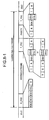
- the FEC system defined in the conventional GE-PON system (IEEE802.3ah (see Non-Patent Document 1)), as shown in Figs. 8-1 and 8-2 , newly defines an S_FEC and a T_FEC.
- the S_FEC is a code for identification of a frame start.
- the T_FEC is a code for identification of a boundary between an IEEE802.3 frame (hereinafter, "frame”) and an FEC parity (hereinafter, "parity”) and for identification of a parity end.
- the S_FEC (/K28.5/D6.4/K28.5/D6.4/K27.7/: Dxx.x indicates a 10-bit data code in the 8B/10B code system) is obtained by extending /S/ (/K27.7/: Kxx.x indicates a 10-bit special code in the 8B/10B code system), which is a frame start identification code in the case of a non-FEC frame.
- the T_FEC (/T/R/K28.5/D29.5(or /D10.1/)/T/R/ or /T/R/R/K28.5/D16.2(or /D5.6/)/T/R/) is obtained by extending an EPD (/T/R or /T/R/R:/T/ indicates /K29.7/ and /R/ indicates /K23.7/), which is a frame end identification code in the case of the non-FEC frame.
- These code patterns for frame boundary identification are added in front of and behind a frame and a parity during frame transmission and outputted to a communication partner apparatus.
- the receiving unit of the communication partner apparatus establishes frame synchronization (detection of a boundary between the frame and the parity) by detecting these code patterns for frame boundary identification.
- frame synchronization detection of a boundary between the frame and the parity
- IEEE802.3ah a certain degree of error (in IEEE802.3ah, smaller than 5 bits) is allowed for these code patterns for the frame boundary identification during frame reception to protect code patterns for frame boundary identification not protected by the FEC function and prevent frame synchronization from being overlooked even when a frame propagates on a transmission channel with a high error rate.
- Non-Patent Document 1 IEEE802.3ah, section 65.2.3
- a process of occurrence of misdetection is shown with a T_FEC of 6 bytes (/T/R/K28.5/D29.5(or /D10.1)/T/R/) as an example. Misdetection of T_FEC also occurs when a T_FEC is a code of 7 bytes (/T/R/R/K28.5/D16.2(or /D5.6/)/T/R/).
- the present invention has been devised in view of the above. It is an object of the present invention to provide a communication apparatus that can reduce the probability of occurrence of misdetection of a T_FEC, which is located between a frame and a parity, without changing the allowable number of errors of a code pattern for frame boundary identification.
- FEC in EPON Technical Proposal refers to the problem of misdetection, and discloses a communication apparatus that performs frame boundary detection using the T_FEC pattern of an IEEE802.3 frame in a frame defined in IEEE802.3ah.
- US 6452991B1 also refers to the problem of misdetection in mobile transmission systems, and suggests to provide code detection with overlapping windows.
- a communication apparatus realizes an FEC function and includes a T_FEC-pattern comparing unit that executes, for each of a plurality of detection windows provided at staggered times, processing for comparing an FEC frame defined in IEEE802.3ah as a reception frame and a T_FEC pattern as a pattern for boundary identification added during transmission and calculates code distances between patterns in the detection windows and the T_FEC pattern one after another; a code-distance comparing unit that compares the code distances calculated for each of the detection windows and detects, based on a result of the comparison, a code for boundary identification T_FEC between an IEEE802.3 frame and an FEC parity; and a boundary-signal generating unit that generates, based on a result of the detection, a T_FEC boundary signal as a signal indicating a detection position (a boundary) of the T_FEC in the FEC frame.
- Fig. 1 is a diagram of a structure of a T_FEC-between-frame-and-parity detecting unit 1 according to a first embodiment of the communication apparatus according to the present invention.
- the T_FEC-between-frame-and-parity detecting unit 1 includes T_FEC-pattern detecting units 11 and 12, a T_FEC-code-distance comparing unit 14, a T_FEC-boundary-signal generating unit 15, and delay elements 16 and 17.
- the T_FEC-pattern detecting units 11 and 12 shown in Fig. 1 compare an FEC frame, which is inputted to the T_FEC-between-frame-and-parity detecting unit 1, and a T_FEC pattern.
- the input FEC frame is delayed by the delay element 16 and the delayed FEC frame is inputted to the T_FEC-pattern detecting unit 12.
- the T_FEC-pattern detecting units 11 and 12 output respective code distances, which is obtained as a result of comparison of the input FEC frame and the T_FEC pattern, to the T_FEC-code-distance comparing unit 14 one after another.
- the T_FEC-code-distance comparing unit 14 compares the code distances received respectively from the T_FEC-pattern detecting units 11 and 12.
- the T_FEC-code-distance comparing unit 14 notifies the T_FEC-boundary-signal generating unit 15 that a pattern detected by the T_FEC-pattern detecting unit 12 is a T_FEC.
- the T_FEC-boundary-signal generating unit 15 generates and outputs a T_FEC boundary signal based on the information notified from the T_FEC-code-distance comparing unit 14. Specifically, the T_FEC boundary signal indicates a position (a boundary) of a T_FEC corresponding to the FEC frame that has passed the delay element 17.
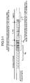
- Figs. 2-1 to 2-3 are diagrams for explaining a T_FEC-between-frame-and-parity detecting method according to the first embodiment. Specifically, states in which code patterns of a frame inputted to a receiving unit are inputted to the T_FEC-pattern detecting units 11 and 12 in order are shown in time series in Figs. 2-1 to 2-3 . 11a and 12a in Figs. 2-1 to 2-3 indicate detection windows employed in the T_FEC-pattern detecting unit 11 and the T_FEC-pattern detecting unit 12, respectively. These detection windows partially overlap each other.
- FIG. 2-1 A state in which 4 bytes at a frame end and 2 bytes at a T_FEC front are in the detection window 11a of the T_FEC-pattern detecting unit 11 is shown in Fig. 2-1 .
- the 4 bytes at the frame end is a pattern that coincides with 4 bytes at a T_FEC front (/T/R/K28.5/D29.5/) within a code distance of 4 bits.
- 4 bytes at a parity front is a pattern that coincides with 4 bytes at a T_FEC end (/K28.5/D29.5/T/R/) within a code distance 4 bits. It is assumed that the original T_FEC has no error.
- Fig. 2-1 A state in which 4 bytes at a frame end and 2 bytes at a T_FEC front are in the detection window 11a of the T_FEC-pattern detecting unit 11 is shown in Fig. 2-1 .
- the 4 bytes at the frame end is a pattern that
- the T_FEC-code-distance comparing unit 14 detects the pattern to a T_FEC pattern.
- the code pattern in the T_FEC detection window 12a is a normal data code and the code distance between the code pattern and the T_FEC pattern is always equal to or larger than 5 bits. Therefore, in the T_FEC detection window 12a, the T_FEC-code-distance comparing unit 14 judges that the code pattern is not a T_FEC and performs nothing.
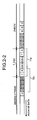
- FIG. 2-2 A state in which the pattern that was in the T_FEC detection window 11a in Fig. 2-1 has now entered into the T_FEC detection window 12a and the T_FEC has entered into the T_FEC detection window 11a is shown in Fig. 2-2 .
- Fig. 2-2 A state in which the pattern that was in the T_FEC detection window 11a in Fig. 2-1 has now entered into the T_FEC detection window 12a and the T_FEC has entered into the T_FEC detection window 11a is shown in Fig. 2-2 .
- Fig. 2-2 In the example shown in Fig.
- the T_FEC-code-distance comparing unit 14 judges that a pattern detected by the T_FEC-pattern detecting unit 12 is a T_FEC and notifies detection of T_FEC to the T_FEC-boundary-signal generating unit 15.
- the T_FEC-code-distance comparing unit 14 performs nothing as in the case shown in Fig. 2-1 .
- the pattern in the T_FEC detection window 11a obviously has a smaller code distance, so that, in this case either, the T_FEC-code-distance comparing unit 14 does not notify the T_FEC-boundary-signal generating unit 15 of the detection of a T_FEC.
- FIG. 2-3 A state in which the T_FEC that was in the T_FEC detection window 11a in Fig. 2-2 has now entered into the T_FEC detection window 12a and the 4 bytes at the parity front enter has entered into the T_FEC detection window 11a is shown in Fig. 2-3 .
- the pattern in the T_FEC detection window 12a has a smaller code distance than the pattern including the 4 bytes at the front of the parity in the T_FEC detection window 11a. Therefore, the T_FEC-code-distance comparing unit 14 notifies detection of the T_FEC to the T_FEC-boundary-signal generating unit 15.
- a position of the T_FEC is judged after checking a T_FEC in an FEC frame and the patterns in front and behind the T_FEC.
- misdetection of the T_FEC will not occur if no error is included in the original T_FEC.
- misdetection of the T_FEC can occur only in a rare situation.
- misdetection of the T_FEC can occur only when the pattern obtained by combining the 4 bytes at the frame end and the 2 bytes at the T_FEC front and the T_FEC pattern coincide with each other at a code distance of 4 bits.
- T_FEC 6 bytes (/T/R/K28.5/D29.5/T/R/) as an example; however, the same effect can be obtained even if the T_FEC is 6 bytes (/T/R/K28.5/D10.1/T/R/) or 7 bytes (/T/R/R/K28.5/D16.2(or /D5.6/)/T/R/).
- Fig. 3 is a diagram of a structure of a T_FEC-between-frame-and-parity detecting unit 1 according to a second embodiment of the communication apparatus according to the present invention.
- a T_FEC-pattern detecting unit 13 and a delay element 18 are newly added and the T_FEC-code-distance comparing unit 14 is replaced with a T_FEC-code-distance comparing unit 19.
- the T_FEC-code-distance comparing unit 19 uses different judgment conditions than those used in the T_FEC-code-distance comparing unit 14.
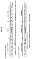
- Fig. 4 is a diagram for explaining a T_FEC-between-frame-and-parity detecting method according to the second embodiment.
- 11a, 12a, and 13a in Fig. 4 correspond to detection windows employed by the T_FEC-pattern detecting units 11, 12, and 13, respectively. Each of the detection windows partially overlaps with the adjacent detection window. Operations of the T_FEC-code-distance comparing unit 19 different from the processing according to the first embodiment are explained below.
- the T_FEC-code-distance comparing unit 19 does not notify detection of a T_FEC to the T_FEC-boundary-signal generating unit 15.
- the T_FEC-code-distance comparing unit 19 does not notify detection of a T_FEC to the T_FEC-boundary-signal generating unit 15.
- the T_FEC-code-distance comparing unit 19 judges that a pattern detected in the T_FEC detection window 13a is a T_FEC and notifies detection of the T_FEC to the T_FEC-boundary-signal generating unit 15.
- the T_FEC-code-distance comparing unit 19 compares the code distance inputted from the T_FEC-pattern detecting unit 12 and the code distance inputted from the T_FEC-pattern detecting unit 13. When the code distance inputted from the T_FEC-pattern detecting unit 13 is smaller, the T_FEC-code-distance comparing unit 19 judges that a pattern detected in the T_FEC detection window 13a is a T_FEC and notifies detection of the T_FEC to the T_FEC-boundary-signal generating unit 15.
- the T_FEC-code-distance comparing unit 19 judges that a pattern detected in the T_FEC detection window 12a is a T_FEC and notifies detection of the T_FEC to the T_FEC-boundary-signal generating unit 15.
- the T_FEC-code-distance comparing unit 19 judges that a pattern detected in the T_FEC detection window 12a is a T_FEC and notifies detection of the T_FEC to the T_FEC-boundary-signal generating unit 15.
- the probability of misdetection of a T_FEC is reduced by using a plurality of T_FEC detection windows.
- misdetection of a T_FEC is prevented by using the relation between the frame length and the parity length.
- Fig. 5 is a diagram of a structure of a frame-boundary detecting unit 2 according to a third embodiment of the communication apparatus according to the present invention.
- the frame-boundary detecting unit 2 includes an S_FEC-pattern detecting unit 21, a T_FEC-pattern detecting unit 22, parity-length checking units 23-1 to 23-n, a frame-boundary-signal generating unit 24, and a delay element 25.
- S_FEC-pattern detecting unit 21 a T_FEC-pattern detecting unit 22
- parity-length checking units 23-1 to 23-n a frame-boundary-signal generating unit 24.
- a delay element 25 In this example, not only a boundary signal of a T_FEC, which is located between a frame and a parity, but also a boundary signal between the frame and the parity are collectively generated.
- the frame-boundary detecting unit 2 shown in Fig. 5 detects an S_FEC and a T_FEC in the inputted FEC frame and generates a boundary signal between a frame and a parity.
- the inputted FEC frame is inputted to each of the S_FEC-pattern detecting unit 21, the T_FEC-pattern detecting unit 22, the parity-length checking units 23-1 to 23-n, and the delay element 25.
- the delay element 25 is an element for synchronizing an FEC frame, which is output, and an FEC frame boundary signal generated by the frame-boundary-signal generating unit 24.
- the S_FEC-pattern detecting unit 21 performs detection of coincidence of the FEC frame with an S_FEC pattern and, when a pattern having a code distance to the FEC frame equal to or smaller than the allowable number of errors (in IEEE8023ah, equal to or smaller than 4 bits) is detected, notifies detection of S_FEC to the frame-boundary-signal generating unit 24.
- the T_FEC-pattern detecting unit 22 performs detection of coincidence of the FEC frame with a T_FEC pattern and, when a pattern having a code distance to the FEC frame equal to or smaller than the allowable number of errors (in IEEE802.3ah, equal to or smaller than 4 bits) is detected, notifies detection of T_FEC to the frame-boundary-signal generating unit 24.
- the frame-boundary-signal generating unit 24 counts a frame length of an IEEE802.3 frame (a frame) from a S_FEC detection signal output from the S_FEC-pattern detecting unit 21 and a T_FEC detection signal output from the T_FEC-pattern detecting unit 22, and outputs the result of the counting, i.e., the frame length, to each of the parity-length checking units 23-1 to 23-n.
- the frame-boundary-signal generating unit 24 counts frame lengths of each of the n T_FECs and outputs result of the counting to a corresponding one of the n parity-length checking units 23-1 to 23-n in order.
- Each of the parity-length checking units 23-1 to 23-n calculates a parity length by using Equation (1) below based on the frame length inputted from the frame-boundary-signal generating unit 24.
- Each of the parity-length checking units 23-1 to 23-n checks whether a pattern having a code distance equal to or smaller than the allowable number of errors (in IEEE802.3ah, equal to or smaller than 4 bits) is present behind the parity. For example, when a unit from among the parity-length checking units 23-1 to 23-n detects such a pattern, that unit notifies the frame-boundary-signal generating unit 24 "yes" and, when such a pattern is not detected, notify the frame-boundary-signal generating unit 24 "no".
- Parity length frame length / 239 ] ⁇ 16 unit : byte
- the frame-boundary-signal generating unit 24 judges that the frame lengths that are outputted by the parity-length checking units from which "yes" is received, i.e., positions of the S_FEC and the T_FEC between the frame and the parity, are correct and outputs an FEC frame boundary signal to a circuit at a post stage.
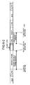
- Figs. 6-1 and 6-2 are diagrams for explaining a T_FEC-between-frame-and-parity detecting method according to this example. Specifically, in Fig. 6-1 , a T_FEC between a frame and a parity is detected normally, i.e., a signal indicating "yes" is returned from one of the parity-length checking units to the frame-boundary-signal generating unit 24. In Fig. 6-2 , a T_FEC between a frame and a parity is not detected normally, i.e., a signal indicating "no" is returned from one of the parity-length checking units to the frame-boundary-signal generating unit 24.
- the frame-boundary-signal generating unit 24 starts counting of a frame length.
- the frame-boundary-signal generating unit 24 stops the counting of the frame length and outputs a result of the counting of the frame length to, for example, the parity-length checking unit 23-1.
- the parity-length checking unit 23-1 performs checking of a parity length based on the result of the counting of a frame length from the frame-boundary-signal generating unit 24 by using Equation (1), and, based on such a checking detects a T_FEC behind the parity, the parity-length checking unit 23-1 notifies the frame-boundary-signal generating unit 24 "yes".
- Fig. 6-2 when the S_FEC-pattern detecting unit 21 detects an S_FEC and the detection of the S_FEC is notified to the frame-boundary-signal generating unit 24, the frame-boundary-signal generating unit 24 starts counting of a frame length.
- the frame-boundary-signal generating unit 24 stops the counting of a frame length, and outputs a result of the counting of a frame length to, for example, the parity-length checking unit 23-2.
- the parity-length checking unit 23-2 performs check of a parity length based on the result of the counting of the frame length from the frame-boundary-signal generating unit 24. However, because a T_FEC is not detected behind the parity, the parity-length checking unit 23-2 notifies the frame-boundary-signal generating unit 24 "no".
- misdetection occurs of a T_FEC, which is located between a frame and a parity, it means that a plurality of T_FECs are detected in one FEC frame. Therefore, when misdetection of a T_FEC occurs, the processing in Fig. 6-1 and the processing in Fig. 6-2 are performed in parallel.
- the relation between a frame length and a parity length is checked to judge a position of a T_FEC.
- a T_FEC that should be correct has a specified code distance to a T_FEC pattern larger than that of a false T_FEC, which cannot be prevented in the first and the second embodiments, it is possible to prevent misdetection of the T_FEC. This makes it possible to reduce the probability of misdetection of a T_FEC more than the first and the second embodiments.
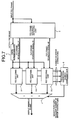
- Fig. 7 is a diagram of a structure according to the further example of the communication apparatus.
- the communication apparatus includes an FEC-frame-boundary detecting unit 3, a 10B/8B converting unit 4, FEC decoding units 5-1 to 5-3, an FEC-error-correction-number comparing unit 6, and a selector 7.
- the FEC-frame-boundary detecting unit 3 shown in Fig. 7 detects an S_FEC and a T_FEC from the inputted FEC frame and generates all possible FEC frame boundary signals.
- the T_FEC detection processing described in the first and the second embodiment can be employed.
- Misdetection of a T_FEC between a frame and a parity is often performed in 4 bytes (or 5 bytes) at the end of the frame and 2 bytes at the front of the T_FEC or performed in 2 bytes at the end of the T_FEC and 4 bytes (or 5 bytes) of the parity.
- a probability of detection of the T_FEC in the middle of the frame is not zero. However, in that case, because the frame has a pattern closer to the T_FEC from the beginning and an error needs to be added in a direction in which a code distance to the T_FEC is smaller on a transmission channel, the probability of occurrence is extremely small.
- maximum three kinds of FEC frame boundary signals are outputted from the FEC-frame-boundary detecting unit 3 to the FEC decoding units 5-1 to 5-3, respectively.
- the number of FEC decoding units can be increased to cope with four or more FEC frame boundary signals.
- the FEC-frame-boundary detecting unit 3 delays the inputted FEC frame by a certain time so that the inputted frame is synchronized with FEC frame boundary signals #1 to #3 and outputs the FEC frame.
- the 10B/8B converting unit 4 converts the FEC frame inputted with a 10B code into a 8B code and outputs the result of the conversion to the FEC decoding units 5-1 to 5-3.
- the FEC decoding units 5-1 to 5-3 separate the frame and the parity based on the FEC frame boundary signals, respectively, and outputs the numbers of error corrections obtained by this processing to the FEC-error-correction-number comparing unit 6.
- the FEC-error-correction-number comparing unit 6 compares the numbers of error corrections outputted from the respective FEC decoding units and switches the selector 7 to output an output of the FEC decoding unit having the smallest number of error corrections to a circuit at a post stage.
- the EC decoding processing is executed based on all the possible FEC frame boundary signals, and the result of the FEC decoding processing with the smallest number of error corrections is outputted to the circuit at the post stage.
- the possibility of misdetection of the T_FEC is eliminated by the use of the combination of the 4 bytes (or 5 bytes) at the end of the frame and the 2 bytes at the front of the T_FEC and the combination of the 2 bytes at the end of the T_FEC and the 4 bytes (or 5 bytes) at the front of the parity.
- the communication apparatus according to the present invention is useful for an optical network of the GE-PON system and, in particular, suitable as a communication apparatus in realizing an FEC function according to the standard of IEEE802.3ah.
Landscapes
- Engineering & Computer Science (AREA)
- Chemical & Material Sciences (AREA)
- Computer Networks & Wireless Communication (AREA)
- Signal Processing (AREA)
- Organic Chemistry (AREA)
- Chemical Kinetics & Catalysis (AREA)
- Medicinal Chemistry (AREA)
- Polymers & Plastics (AREA)
- Health & Medical Sciences (AREA)
- General Physics & Mathematics (AREA)
- Condensed Matter Physics & Semiconductors (AREA)
- Physics & Mathematics (AREA)
- Computer Hardware Design (AREA)
- Microelectronics & Electronic Packaging (AREA)
- Power Engineering (AREA)
- Detection And Prevention Of Errors In Transmission (AREA)
- Synchronisation In Digital Transmission Systems (AREA)
- Compositions Of Macromolecular Compounds (AREA)
- Paints Or Removers (AREA)
Applications Claiming Priority (1)
| Application Number | Priority Date | Filing Date | Title |
|---|---|---|---|
| PCT/JP2006/312742 WO2008001419A1 (fr) | 2006-06-26 | 2006-06-26 | Dispositif de communication |
Publications (3)
| Publication Number | Publication Date |
|---|---|
| EP2034657A1 EP2034657A1 (en) | 2009-03-11 |
| EP2034657A4 EP2034657A4 (en) | 2011-03-02 |
| EP2034657B1 true EP2034657B1 (en) | 2014-01-15 |
Family
ID=38845197
Family Applications (1)
| Application Number | Title | Priority Date | Filing Date |
|---|---|---|---|
| EP06767359.0A Ceased EP2034657B1 (en) | 2006-06-26 | 2006-06-26 | GE-PON communication device |
Country Status (6)
| Country | Link |
|---|---|
| US (1) | US8719674B2 (zh) |
| EP (1) | EP2034657B1 (zh) |
| JP (1) | JP4322946B2 (zh) |
| KR (2) | KR100936857B1 (zh) |
| CN (1) | CN101233715B (zh) |
| WO (1) | WO2008001419A1 (zh) |
Families Citing this family (8)
| Publication number | Priority date | Publication date | Assignee | Title |
|---|---|---|---|---|
| CN101997628B (zh) * | 2009-08-28 | 2013-08-14 | 国际商业机器公司 | 以太网前向纠错层接收的数据流的帧边界检测方法和系统 |
| CN102185677A (zh) * | 2011-04-26 | 2011-09-14 | 中兴通讯股份有限公司 | 模式匹配认证码的生成方法、自动配置方法、设备和系统 |
| ES2625528T3 (es) * | 2011-10-31 | 2017-07-19 | Huawei Technologies Co., Ltd. | Dispositivo de envío de datos, dispositivo de recepción de datos y método de sincronización de tramas |
| JP5960586B2 (ja) * | 2012-12-17 | 2016-08-02 | 日本電信電話株式会社 | フレーム処理回路および方法 |
| JP5712995B2 (ja) * | 2012-12-20 | 2015-05-07 | トヨタ自動車株式会社 | 通信システム、通信装置及び通信方法 |
| CN110784283B (zh) * | 2014-07-22 | 2022-01-14 | 华为技术有限公司 | 确定前向纠错帧边界的方法、装置和解码系统 |
| DE102020114547B4 (de) * | 2020-05-29 | 2023-12-28 | Infineon Technologies Ag | Vorrichtung und verfahren zum abwickeln eines eingehenden kommunikations-datenrahmens |
| CN111901217B (zh) * | 2020-06-05 | 2021-11-02 | 吉林大学 | 一种基于微振感知的重点区域陆空一体警戒系统 |
Family Cites Families (22)
| Publication number | Priority date | Publication date | Assignee | Title |
|---|---|---|---|---|
| US5037862A (en) | 1987-06-11 | 1991-08-06 | Hitachi Chemical Company, Ltd. | Polyamide-imide resin pastes |
| JP2697215B2 (ja) * | 1988-12-29 | 1998-01-14 | 日立化成工業株式会社 | 耐熱樹脂ペーストおよびこれを用いたic |
| EP0626771A3 (de) * | 1993-05-26 | 1998-04-29 | Ascom Tech Ag | Verfahren und Vorrichtung zum Ermitteln einer jeweiligen Abtastphase und zum nachfolgenden Abtasten der Bits eines Datenpakets |
| JPH10117190A (ja) * | 1996-10-08 | 1998-05-06 | Oki Electric Ind Co Ltd | バースト信号再生回路 |
| JP3318243B2 (ja) * | 1997-09-30 | 2002-08-26 | 株式会社日立国際電気 | フレーム同期回路及びそれを用いた受信機 |
| JPH11298467A (ja) * | 1998-04-07 | 1999-10-29 | Toshiba Corp | フレーム同期方式 |
| US6452991B1 (en) * | 1998-12-30 | 2002-09-17 | Ericsson Inc. | Systems and methods for acquiring channel synchronization in time division multiple access communications systems using dual detection thresholds |
| JP3395967B2 (ja) * | 2000-01-14 | 2003-04-14 | 日本電気株式会社 | ユニークワード検出窓補正装置 |
| GB2371952A (en) | 2001-01-31 | 2002-08-07 | Inmarsat Ltd | Frame synchronisation in a communication system |
| JP2005524281A (ja) | 2002-04-25 | 2005-08-11 | パッセイヴ リミテッド | イーサネット(登録商標)ネットワークにおける前方誤り訂正コーディング |
| JP4244568B2 (ja) * | 2002-06-12 | 2009-03-25 | 日本ビクター株式会社 | 再生装置、再生方法及びプログラム |
| US6782325B2 (en) * | 2002-09-30 | 2004-08-24 | Micro Motion, Inc. | Programmable coriolis flow meter electronics for outputting information over a single output port |
| KR20040035288A (ko) * | 2002-10-19 | 2004-04-29 | 삼성전자주식회사 | 수신성능을 향상시키는 다중 반송파 송신 시스템 및 그의신호처리방법 |
| AU2003288498A1 (en) * | 2002-12-16 | 2004-07-09 | Passave Ltd. | Method of ethernet frame forward error correction initialization and auto-negotiation |
| GB2402307A (en) * | 2003-05-30 | 2004-12-01 | Nokia Corp | Encapsulating irregular burst transmissions with overhead information specifying the timing interval to the next burst |
| KR100547828B1 (ko) * | 2003-12-18 | 2006-01-31 | 삼성전자주식회사 | 데이터를 안전하게 전송하기 위해 데이터의 오류를 보다정확하게 검출할 수 있는 기가비트 이더넷 기반의 수동광가입자망 및 그 방법 |
| US7581155B2 (en) * | 2003-12-18 | 2009-08-25 | Electronics And Telecommunications Research Institute | Apparatus for FEC supporting transmission of variable-length frames in TDMA system and method of using the same |
| US7600171B2 (en) * | 2003-12-18 | 2009-10-06 | Electronics And Telecommunications Research Institute | Method of controlling FEC in EPON |
| US7152199B2 (en) * | 2004-06-02 | 2006-12-19 | Teknovus, Inc. | Method and apparatus for delineating data in an FEC-coded Ethernet frame |
| JP2006164490A (ja) * | 2004-11-10 | 2006-06-22 | Victor Co Of Japan Ltd | 同期信号検出装置、同期信号検出方法、及び同期信号検出プログラム |
| US20070104225A1 (en) * | 2005-11-10 | 2007-05-10 | Mitsubishi Denki Kabushiki Kaisha | Communication apparatus, transmitter, receiver, and error correction optical communication system |
| US7890840B2 (en) * | 2006-03-03 | 2011-02-15 | Pmc-Sierra Israel Ltd. | Enhancing the Ethernet FEC state machine to strengthen correlator performance |
-
2004
- 2004-09-28 KR KR1020077005208A patent/KR100936857B1/ko not_active IP Right Cessation
-
2006
- 2006-06-26 KR KR1020077022269A patent/KR100936829B1/ko not_active IP Right Cessation
- 2006-06-26 US US11/817,907 patent/US8719674B2/en not_active Expired - Fee Related
- 2006-06-26 CN CN2006800102155A patent/CN101233715B/zh not_active Expired - Fee Related
- 2006-06-26 WO PCT/JP2006/312742 patent/WO2008001419A1/ja active Application Filing
- 2006-06-26 EP EP06767359.0A patent/EP2034657B1/en not_active Ceased
- 2006-06-26 JP JP2007505299A patent/JP4322946B2/ja active Active
Also Published As
| Publication number | Publication date |
|---|---|
| CN101233715A (zh) | 2008-07-30 |
| US8719674B2 (en) | 2014-05-06 |
| EP2034657A4 (en) | 2011-03-02 |
| US20090254793A1 (en) | 2009-10-08 |
| KR100936829B1 (ko) | 2010-01-14 |
| CN101233715B (zh) | 2012-09-12 |
| JPWO2008001419A1 (ja) | 2009-11-19 |
| EP2034657A1 (en) | 2009-03-11 |
| JP4322946B2 (ja) | 2009-09-02 |
| KR100936857B1 (ko) | 2010-01-14 |
| KR20080026083A (ko) | 2008-03-24 |
| WO2008001419A1 (fr) | 2008-01-03 |
| KR20070040834A (ko) | 2007-04-17 |
Similar Documents
| Publication | Publication Date | Title |
|---|---|---|
| EP2034657B1 (en) | GE-PON communication device | |
| EP1805636B1 (en) | Slave bus subscriber for a serial data bus | |
| JP4855157B2 (ja) | ビット速度判定装置 | |
| US7474723B2 (en) | DSRC communication circuit and communication method | |
| US8538257B2 (en) | Apparatus and method for performing line analysis of continuous data signals | |
| CN101072078A (zh) | 解码aes-3数字音频数据流的两相解码器 | |
| EP0563936B1 (en) | Frame synchronization circuit for digital communication system | |
| JP2861932B2 (ja) | バーストフレーム位相同期回路 | |
| US20020150118A1 (en) | Communication system, method and signal for time-slot-coded data transmission | |
| US5533039A (en) | Fault tolerant fiber optic protocol for determining beginning of data | |
| KR20030075140A (ko) | 데이터의 위치 정보 탐색을 통한 데이터 복원 방법 및상기 알고리즘을 적용한 직렬 데이터 수신기 | |
| CN102737208A (zh) | 一种超高频电子标签译码mmc型数据的方法 | |
| CN107925513B (zh) | 错误监视设备、方法和记录介质 | |
| CN100578970C (zh) | 延时固定的级联网络及其节点绑定方法 | |
| EP3731231B1 (en) | Slip detection on high speed data links | |
| JP2768303B2 (ja) | 誤り訂正回路 | |
| JP4984054B2 (ja) | フレーム同期装置およびフレーム同期方法 | |
| US20030103529A1 (en) | Deframer | |
| JPH0818611A (ja) | 光伝送装置 | |
| KR100212051B1 (ko) | 데이타 수신 장치 및 방법 | |
| JP5960586B2 (ja) | フレーム処理回路および方法 | |
| JPH0629964A (ja) | フレームパルス検出回路 | |
| JPH0456500B2 (zh) | ||
| JPS60192440A (ja) | 回線品質監視回路 | |
| JPH06350589A (ja) | フレーム同期検出回路 |
Legal Events
| Date | Code | Title | Description |
|---|---|---|---|
| PUAI | Public reference made under article 153(3) epc to a published international application that has entered the european phase |
Free format text: ORIGINAL CODE: 0009012 |
|
| 17P | Request for examination filed |
Effective date: 20070904 |
|
| AK | Designated contracting states |
Kind code of ref document: A1 Designated state(s): AT BE BG CH CY CZ DE DK EE ES FI FR GB GR HU IE IS IT LI LT LU LV MC NL PL PT RO SE SI SK TR |
|
| AX | Request for extension of the european patent |
Extension state: AL BA HR MK RS |
|
| DAX | Request for extension of the european patent (deleted) | ||
| RBV | Designated contracting states (corrected) |
Designated state(s): DE FR GB |
|
| RIC1 | Information provided on ipc code assigned before grant |
Ipc: H04L 12/44 20060101ALI20110120BHEP Ipc: H04L 7/08 20060101ALI20110120BHEP Ipc: H04L 7/04 20060101AFI20110120BHEP |
|
| A4 | Supplementary search report drawn up and despatched |
Effective date: 20110128 |
|
| REG | Reference to a national code |
Ref country code: DE Ref legal event code: R079 Ref document number: 602006040088 Country of ref document: DE Free format text: PREVIOUS MAIN CLASS: H04L0007080000 Ipc: H04L0007040000 |
|
| GRAJ | Information related to disapproval of communication of intention to grant by the applicant or resumption of examination proceedings by the epo deleted |
Free format text: ORIGINAL CODE: EPIDOSDIGR1 |
|
| GRAP | Despatch of communication of intention to grant a patent |
Free format text: ORIGINAL CODE: EPIDOSNIGR1 |
|
| RIC1 | Information provided on ipc code assigned before grant |
Ipc: H04L 12/44 20060101ALI20130710BHEP Ipc: H04L 7/04 20060101AFI20130710BHEP Ipc: H04B 10/272 20130101ALN20130710BHEP |
|
| INTG | Intention to grant announced |
Effective date: 20130723 |
|
| GRAS | Grant fee paid |
Free format text: ORIGINAL CODE: EPIDOSNIGR3 |
|
| GRAA | (expected) grant |
Free format text: ORIGINAL CODE: 0009210 |
|
| AK | Designated contracting states |
Kind code of ref document: B1 Designated state(s): DE FR GB |
|
| REG | Reference to a national code |
Ref country code: GB Ref legal event code: FG4D |
|
| REG | Reference to a national code |
Ref country code: DE Ref legal event code: R096 Ref document number: 602006040088 Country of ref document: DE Effective date: 20140220 |
|
| REG | Reference to a national code |
Ref country code: DE Ref legal event code: R097 Ref document number: 602006040088 Country of ref document: DE |
|
| PLBE | No opposition filed within time limit |
Free format text: ORIGINAL CODE: 0009261 |
|
| STAA | Information on the status of an ep patent application or granted ep patent |
Free format text: STATUS: NO OPPOSITION FILED WITHIN TIME LIMIT |
|
| 26N | No opposition filed |
Effective date: 20141016 |
|
| REG | Reference to a national code |
Ref country code: DE Ref legal event code: R097 Ref document number: 602006040088 Country of ref document: DE Effective date: 20141016 |
|
| REG | Reference to a national code |
Ref country code: FR Ref legal event code: PLFP Year of fee payment: 11 |
|
| REG | Reference to a national code |
Ref country code: DE Ref legal event code: R084 Ref document number: 602006040088 Country of ref document: DE |
|
| REG | Reference to a national code |
Ref country code: GB Ref legal event code: 746 Effective date: 20160519 |
|
| REG | Reference to a national code |
Ref country code: FR Ref legal event code: PLFP Year of fee payment: 12 |
|
| PGFP | Annual fee paid to national office [announced via postgrant information from national office to epo] |
Ref country code: GB Payment date: 20170621 Year of fee payment: 12 Ref country code: FR Payment date: 20170511 Year of fee payment: 12 |
|
| PGFP | Annual fee paid to national office [announced via postgrant information from national office to epo] |
Ref country code: DE Payment date: 20170621 Year of fee payment: 12 |
|
| REG | Reference to a national code |
Ref country code: DE Ref legal event code: R119 Ref document number: 602006040088 Country of ref document: DE |
|
| GBPC | Gb: european patent ceased through non-payment of renewal fee |
Effective date: 20180626 |
|
| PG25 | Lapsed in a contracting state [announced via postgrant information from national office to epo] |
Ref country code: DE Free format text: LAPSE BECAUSE OF NON-PAYMENT OF DUE FEES Effective date: 20190101 Ref country code: FR Free format text: LAPSE BECAUSE OF NON-PAYMENT OF DUE FEES Effective date: 20180630 Ref country code: GB Free format text: LAPSE BECAUSE OF NON-PAYMENT OF DUE FEES Effective date: 20180626 |