EP2031319A1 - Mauerkasten mit motorisch betätigter Klappe - Google Patents
Mauerkasten mit motorisch betätigter Klappe Download PDFInfo
- Publication number
- EP2031319A1 EP2031319A1 EP08001188A EP08001188A EP2031319A1 EP 2031319 A1 EP2031319 A1 EP 2031319A1 EP 08001188 A EP08001188 A EP 08001188A EP 08001188 A EP08001188 A EP 08001188A EP 2031319 A1 EP2031319 A1 EP 2031319A1
- Authority
- EP
- European Patent Office
- Prior art keywords
- wall box
- cover
- lid
- frame part
- drive
- Prior art date
- Legal status (The legal status is an assumption and is not a legal conclusion. Google has not performed a legal analysis and makes no representation as to the accuracy of the status listed.)
- Granted
Links
- 239000011810 insulating material Substances 0.000 claims description 3
- 238000005259 measurement Methods 0.000 claims description 3
- 238000007789 sealing Methods 0.000 claims 1
- 238000009434 installation Methods 0.000 description 6
- 238000013461 design Methods 0.000 description 4
- XLYOFNOQVPJJNP-UHFFFAOYSA-N water Substances O XLYOFNOQVPJJNP-UHFFFAOYSA-N 0.000 description 3
- 230000001419 dependent effect Effects 0.000 description 2
- 238000005286 illumination Methods 0.000 description 2
- 238000012986 modification Methods 0.000 description 2
- 230000004048 modification Effects 0.000 description 2
- 230000002093 peripheral effect Effects 0.000 description 2
- 229920003023 plastic Polymers 0.000 description 2
- 239000004033 plastic Substances 0.000 description 2
- 229920005830 Polyurethane Foam Polymers 0.000 description 1
- 230000006978 adaptation Effects 0.000 description 1
- 229910052782 aluminium Inorganic materials 0.000 description 1
- XAGFODPZIPBFFR-UHFFFAOYSA-N aluminium Chemical compound [Al] XAGFODPZIPBFFR-UHFFFAOYSA-N 0.000 description 1
- 238000005452 bending Methods 0.000 description 1
- 230000002950 deficient Effects 0.000 description 1
- 238000006073 displacement reaction Methods 0.000 description 1
- 230000010354 integration Effects 0.000 description 1
- 238000012423 maintenance Methods 0.000 description 1
- 229910052751 metal Inorganic materials 0.000 description 1
- 239000002184 metal Substances 0.000 description 1
- 238000000034 method Methods 0.000 description 1
- 239000011496 polyurethane foam Substances 0.000 description 1
Images


Classifications
-
- F—MECHANICAL ENGINEERING; LIGHTING; HEATING; WEAPONS; BLASTING
- F24—HEATING; RANGES; VENTILATING
- F24F—AIR-CONDITIONING; AIR-HUMIDIFICATION; VENTILATION; USE OF AIR CURRENTS FOR SCREENING
- F24F7/00—Ventilation
- F24F7/007—Ventilation with forced flow
- F24F7/013—Ventilation with forced flow using wall or window fans, displacing air through the wall or window
-
- F—MECHANICAL ENGINEERING; LIGHTING; HEATING; WEAPONS; BLASTING
- F24—HEATING; RANGES; VENTILATING
- F24F—AIR-CONDITIONING; AIR-HUMIDIFICATION; VENTILATION; USE OF AIR CURRENTS FOR SCREENING
- F24F11/00—Control or safety arrangements
- F24F11/70—Control systems characterised by their outputs; Constructional details thereof
- F24F11/72—Control systems characterised by their outputs; Constructional details thereof for controlling the supply of treated air, e.g. its pressure
- F24F11/74—Control systems characterised by their outputs; Constructional details thereof for controlling the supply of treated air, e.g. its pressure for controlling air flow rate or air velocity
-
- F—MECHANICAL ENGINEERING; LIGHTING; HEATING; WEAPONS; BLASTING
- F24—HEATING; RANGES; VENTILATING
- F24C—DOMESTIC STOVES OR RANGES ; DETAILS OF DOMESTIC STOVES OR RANGES, OF GENERAL APPLICATION
- F24C15/00—Details
- F24C15/20—Removing cooking fumes
- F24C15/2021—Arrangement or mounting of control or safety systems
-
- F—MECHANICAL ENGINEERING; LIGHTING; HEATING; WEAPONS; BLASTING
- F24—HEATING; RANGES; VENTILATING
- F24F—AIR-CONDITIONING; AIR-HUMIDIFICATION; VENTILATION; USE OF AIR CURRENTS FOR SCREENING
- F24F11/00—Control or safety arrangements
- F24F11/0001—Control or safety arrangements for ventilation
-
- F—MECHANICAL ENGINEERING; LIGHTING; HEATING; WEAPONS; BLASTING
- F24—HEATING; RANGES; VENTILATING
- F24F—AIR-CONDITIONING; AIR-HUMIDIFICATION; VENTILATION; USE OF AIR CURRENTS FOR SCREENING
- F24F11/00—Control or safety arrangements
- F24F11/30—Control or safety arrangements for purposes related to the operation of the system, e.g. for safety or monitoring
-
- F—MECHANICAL ENGINEERING; LIGHTING; HEATING; WEAPONS; BLASTING
- F24—HEATING; RANGES; VENTILATING
- F24F—AIR-CONDITIONING; AIR-HUMIDIFICATION; VENTILATION; USE OF AIR CURRENTS FOR SCREENING
- F24F13/00—Details common to, or for air-conditioning, air-humidification, ventilation or use of air currents for screening
- F24F13/08—Air-flow control members, e.g. louvres, grilles, flaps or guide plates
- F24F13/10—Air-flow control members, e.g. louvres, grilles, flaps or guide plates movable, e.g. dampers
- F24F13/14—Air-flow control members, e.g. louvres, grilles, flaps or guide plates movable, e.g. dampers built up of tilting members, e.g. louvre
- F24F13/1426—Air-flow control members, e.g. louvres, grilles, flaps or guide plates movable, e.g. dampers built up of tilting members, e.g. louvre characterised by actuating means
-
- F—MECHANICAL ENGINEERING; LIGHTING; HEATING; WEAPONS; BLASTING
- F24—HEATING; RANGES; VENTILATING
- F24F—AIR-CONDITIONING; AIR-HUMIDIFICATION; VENTILATION; USE OF AIR CURRENTS FOR SCREENING
- F24F7/00—Ventilation
- F24F2007/001—Ventilation with exhausting air ducts
-
- F—MECHANICAL ENGINEERING; LIGHTING; HEATING; WEAPONS; BLASTING
- F24—HEATING; RANGES; VENTILATING
- F24F—AIR-CONDITIONING; AIR-HUMIDIFICATION; VENTILATION; USE OF AIR CURRENTS FOR SCREENING
- F24F7/00—Ventilation
- F24F2007/0025—Ventilation using vent ports in a wall
-
- F—MECHANICAL ENGINEERING; LIGHTING; HEATING; WEAPONS; BLASTING
- F24—HEATING; RANGES; VENTILATING
- F24F—AIR-CONDITIONING; AIR-HUMIDIFICATION; VENTILATION; USE OF AIR CURRENTS FOR SCREENING
- F24F13/00—Details common to, or for air-conditioning, air-humidification, ventilation or use of air currents for screening
- F24F13/08—Air-flow control members, e.g. louvres, grilles, flaps or guide plates
- F24F13/10—Air-flow control members, e.g. louvres, grilles, flaps or guide plates movable, e.g. dampers
- F24F13/14—Air-flow control members, e.g. louvres, grilles, flaps or guide plates movable, e.g. dampers built up of tilting members, e.g. louvre
- F24F13/1426—Air-flow control members, e.g. louvres, grilles, flaps or guide plates movable, e.g. dampers built up of tilting members, e.g. louvre characterised by actuating means
- F24F2013/1433—Air-flow control members, e.g. louvres, grilles, flaps or guide plates movable, e.g. dampers built up of tilting members, e.g. louvre characterised by actuating means with electric motors
-
- F—MECHANICAL ENGINEERING; LIGHTING; HEATING; WEAPONS; BLASTING
- F24—HEATING; RANGES; VENTILATING
- F24F—AIR-CONDITIONING; AIR-HUMIDIFICATION; VENTILATION; USE OF AIR CURRENTS FOR SCREENING
- F24F2110/00—Control inputs relating to air properties
-
- F—MECHANICAL ENGINEERING; LIGHTING; HEATING; WEAPONS; BLASTING
- F24—HEATING; RANGES; VENTILATING
- F24F—AIR-CONDITIONING; AIR-HUMIDIFICATION; VENTILATION; USE OF AIR CURRENTS FOR SCREENING
- F24F2140/00—Control inputs relating to system states
- F24F2140/60—Energy consumption
Definitions
- the present invention relates to a wall box with a movable by means of a motor drive between an open and a closed position lid.
- the object is achieved for a generic wall box by the lid is rotatable about an axis of rotation which is transverse to the passage direction of the air flowing through the wall box, and the lid by means of a rotational movement about the axis of rotation between the open and closed positions back and forth is.
- the lid By the rotation of the lid about a transverse to the passage direction of the air flowing through the wall box air only a short rotational movement of Dekekels is to be carried out.
- the lid When rotated by only 90 °, the lid can be moved from a closed to a fully open position.
- the axis of rotation passes through the central region of the cover, during the pivoting movement the upper and lower parts of the cover are pivoted in opposite directions, one part in the direction of the fan tube and the other part towards the outside.
- the cover may also only touch or pass through an edge region of the cover, but then it is not readily possible to at least partially immerse the cover in an open position in the ventilator tube.
- the drive motor can be easily arranged in the cover, in the fan tube or outside the fan tube.
- the installation is simple, and since the drive motor no longer has to be mounted in the air flow, it does not so easily pollute. Also, the adjusting mechanism is no longer exposed to the air flow with a possible dirt load, could be blocked by the mechanics.
- the lid is provided with one or more Hohlkammem that can be filled with a heat-insulating material such as polyurethane foam or even air, so that hardly heat losses occur through the wall box in a closed position of the lid.
- a heat-insulating material such as polyurethane foam or even air
- the lid is then somewhat thicker, in the open position still remains a sufficiently large cross-section to allow enough air to flow through.
- the tightness of the joints in the closed position against wind and water between the cover and the frame part can be increased by one or more seals. It is advantageous to design the seal as an abutment seal, since this can then not be worn out by a large number of opening and closing cycles.
- the peripheral shape of the lid should be chosen so that the lid covers in the closed position with its outwardly facing surface more than two-thirds of the inner cross-sectional area of the fan tube. If possible, the surface of the lid of the inner cross-sectional area should even correspond at least approximately, since then the theoretical throughput capacity of the fan tube is not limited by a too small sized lid.
- the peripheral shape of the lid should be designed so that the air flowing through the wall box air can pass through the lid as possible unhindered and no unnecessary deflections of the air flow occur. So it is advantageous to make the lid round, although the fan tube is round, but also oval or angular designs are possible.
- the installation of the wall box in a wall can be accomplished in a simple manner by the fan tube inserted into the prepared wall recess and the frame part is inserted together with the lid held therein in the fan tube from the outside.
- the parts can be made to fit so that the assembly is completed.
- the lid and the frame part can be delivered ready pre-assembled.
- the frame part so that it can be pushed from the inside to the mounting position.
- a design is particularly interesting when the wall box is to be installed in a poorly accessible height in a building, for example, in a higher floor of a high-rise building.
- the fan tube can first be inserted in particular from the inside into a prepared recess in the building wall and fixed in position there. Thereafter, the frame part is also inserted in particular from the inside into the fan tube, brought into the final mounting position and fixed in position there.
- the position fixing can be done for example by a latching connection of the frame part with the fan tube.
- One or more latching lugs which are fastened to a flexible lug, engage on reaching a desired position in a recess located in the inner surface of the fan duct.
- the latching connection can be repealed by bending back the tab, for example with a screwdriver, in particular from the inside of the building, so that the frame part can then be pulled out of the ventilator tube inwardly together with the lid and the motor located therein. In this way it is possible to get the cover and the motor even after the installation of the wall box in a building wall for maintenance or repair work from the fan pipe into the building, without having to get from the outside of the fan tube.
- the motor drive is designed as a pivot bearing for the lid.
- the motor drive protrudes at least partially into the lid, and the contact area between the housing of the motor drive and the lid can then be configured as a pivot bearing.
- the lid thus turns around the motor drive.
- expensive structures for supporting the lid on the one hand and for transmitting the driving force of the motor from a remote location to the lid are avoided, because the motor drive and the lid are so in immediate vicinity.
- the output shaft of the motor is arranged concentrically to the axis of rotation of the lid, only a frictional connection between the output shaft and the surrounding lid must be made to convert the rotational movement of the motor into a rotational movement of the lid.
- the drive motor in the cover of the drive motor can be designed as a sleeve inserted into a recess provided in the lid.
- the sleeve can be rotatably inserted into a fan tube or frame part-sided fixed bearing. Then, on the fixed bearing side of the sleeve connecting elements for connection to a power supply may be present without rotary feedthroughs or the like would be required.
- this sensor signal can be used to turn on the drive motor to thereby open the cover of the wall box. If the sensor reports that the blower has been switched off because there is no more current flowing to the blower, this sensor signal can be used by the control to activate the drive motor to close the cover again. In this way, the opening and closing of the lid of the wall box can be made dependent on the operating condition of a fan, without it being necessary to provide the fan with a separate interface for the connection of the wall box. It is sufficient to place the sensor for power measurement near a live cable of the blower. Thus, the control of the wall box can be connected to any fan of any manufacturer.
- the lid with the controller not, partially or completely open. For example, it may be undesirable to open the lid when only the lighting is switched on at an extractor hood. In this case, the lid remains closed, as long as the illumination is consumed only for example, a power of 30W.
- the self-learning feature allows the controller to adapt to different blowers during installation without the need for special adaptation work by the installation personnel.
- Fig. 1 is a view of a wall box 2 seen from the, in which the lid 4 is in a closed position.
- the lid 4 On the outside of the wall box 2, the lid 4 is framed by the frame part 6, with which the outwardly facing end face of the fan tube 12 and the adjoining edges of the wall opening are covered.
- the wall box 2 is only slightly outward over the wall before, in the closed position of the lid 4 results in a smooth, closed surface, the water, wind and vandalism little attack surface offers.
- the cover 4 and the frame part 6 may be made of plastic or a metal, for example aluminum, or the components made of plastic are provided with a metallic cover, which may be additionally painted.
- the cover 4 In order to move from the closed position into an open position, the cover 4 is rotated about the axis of rotation 10 indicated by a dashed line.
- the axis of rotation 10 runs not only through the central region of the lid 4, but exactly through the symmetry axis of the lid 4th
- Fig. 2 shows a sectional view taken along the line AA in Fig. 1 with closed cover 4 along the length of a wall box 2.
- the passage direction of the air through the wall box is indicated by the double arrow, depending on whether air is to be transported from outside to inside or in the opposite direction.
- the fan tube 12 is formed in several parts in the illustrated embodiment, so that it can be adapted to different wall thicknesses by inserting or removing a pipe section.
- the frame part 6 is placed with the lid 4 on the front side of the fan tube 12.
- the cover 4 in the upper and lower region has hollow chambers 14, which may be filled with a heat-insulating material.
- the lid 4 is designed so that it would theoretically be pivotable in two directions. However, it is also possible to make the cross-sectional contour of the cover 4 differing from the embodiment so that there are attacks by which the rotation is blocked in one direction.
- the gap 8 between the lid 4 and the frame part 6 may also be designed in a staircase to create a labyrinth through which water and wind in a closed position of the lid 4 can pass through heavier.
- a stop 18 is shown on the inside of the frame part 6, by the pivoting movement of the lid 4 is limited to a 90 ° angle.
- the frame part 6 has an inner collar 20, with which the frame part 6 is inserted into the fan tube 12. With the inner collar 20, the frame part 6 together with the built-in cover 4 is easy to install.
- the outwardly facing end of the fan tube 12 has an outer collar 22 which is covered by the frame part 6 after its assembly.
- Fig. 3 is a sectional view taken along the line BB in FIG Fig. 2 shown with closed lid. Opposite the in Fig. 2 shown sectional view is rotated by the 90 ° rotated cutting plane in Fig. 3 the integration of the drive 16 in the lid 4 recognizable.
- the drive 16 is rotatably supported in the frame part 6 with its the wall of the fan tube 12 facing the end.
- the output shaft 24 is rotatably supported concentrically to the axis of rotation 10 and on the opposite end of the drive 16 of the wall of the fan tube 12. With a fixed connection of the output shaft 24 with the cover 4 and a pivotal mounting of the cover 4 on the drive 16 results in a rotational movement of the lid 4 to the drive 16 around when the drive 16 is actuated.
- Fig. 4 is a sectional view taken along the line AA in Fig. 1 shown with lid 4 open.
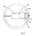
- Fig. 6 the motor 26 and the planetary gear 28 are formed, which together form the drive 16.
- the planetary gear 28 it is possible to reduce the higher speeds of a commercial electric motor to a speed level that fits the specific application. So an opening time of 1 s to 5 s would be completely sufficient.
- the planetary gear 28 in the drive 16 can be dispensed with.
- the drive 16 is installed in a sleeve 30, which can be easily inserted into a recess 32 provided for receiving the sleeve 30. As a result, the assembly is simplified, and even in case of repair, it is easy to replace a defective drive for a spare part.
- Fig. 6 It can be seen that the lid 4 is rotatably supported on the drive 16 via a movable bearing 34.
- the drive 16 is connected on its fan tube wall facing the end in a fixed bearing 36 with the frame part 6. Due to the fixed arrangement of the wall-side end of the drive 16 can be provided there with drawing not shown connecting elements for a power supply of the drive 16 such as sockets.
- the invention is not limited to the above embodiment.
- the person skilled in the art is capable of adapting the principle of the invention in a manner which seems suitable to him by means of modifications to a specific application.
Abstract
Description
- Die vorliegende Erfindung bezieht sich auf einen Mauerkasten mit einem mittels eines motorischen Antriebs zwischen einer Offen- und einer Schließstellung verlagerbaren Deckel.
- Aus der Schrift
DE 20 2005 010 912 ist ein gattungsgemäßer Mauerkasten bekannt. Der Deckel kann mittels eines motorischen Antriebs in axialer Richtung des Lüfterrohrs zwischen einer Offen- und Schließstellung hin und her verfahren werden. Es hat sich allerdings herausgestellt, dass der Antrieb zu aufwendig ist in der Montage. Zudem muss der Antriebsmotor eine vergleichsweise hohe Antriebsleistung aufweisen, um den Deckel nahe der Schließstellung über die anliegenden Dichtungen ziehen oder schieben zu können, wodurch sich der Antrieb nochmals verteuert. Zudem kann der Antriebsmotor leicht verschmutzen, weil er mitten im Luftstrom des Lüfterrohres angeordnet ist. - Demgemäß ist es die Aufgabe der vorliegenden Erfindung, einen Mauerkasten zu schaffen, bei dem der Antrieb zur Verlagerung des Deckels von einer Offen- in eine Schließstellung und umgekehrt einfacher gestaltet werden kann.
- Die Aufgabe wird für einen gattungsgemäßen Mauerkasten gelöst, indem der Deckel um eine Drehachse drehbar ist, die quer zur Durchtrittsrichtung der durch den Mauerkasten strömenden Luft liegt, und der Deckel mittels einer Drehbewegung um die Drehachse zwischen der Offen- und der Schließstellung hin und her verlagerbar ist.
- Durch die Drehung des Deckels um eine quer zur Durchtrittsrichtung der durch den Mauerkasten strömenden Luft ist nur noch eine kurze Rotationsbewegung des Dekkels auszuführen. Bei einer Drehung um nur 90° kann der Deckel aus einer geschlossenen in eine voll geöffnete Stellung verlagert werden. Durchläuft die Drehachse dem mittleren Bereich des Deckels, werden bei der Schwenkbewegung der obere und der untere Teil des Deckels gegensinnig verschwenkt, und zwar ein Teil in Richtung des Lüfterrohrs und der andere Teil nach außen hin. Die Drehachse kann nach einer anderen Ausgestaltung der Erfindung den Deckel auch nur tangieren oder einen Randbereich des Deckels durchlaufen, allerdings ist es dann nicht ohne weiteres möglich, den Deckel in einer Offenstellung zumindest teilweise in das Lüfterrohr eintauchen zu lassen. Für die Drehbewegung ist kein großer Kraftaufwand erforderlich, demgemäß reicht ein kleiner kostengünstiger Antriebsmotor aus. Der Antriebsmotor kann leicht im Deckel, im Lüfterrohr oder außerhalb des Lüfterrohrs angeordnet werden. Die Montage ist einfach, und da der Antriebsmotor nicht mehr im Luftstrom angebracht sein muss, verschmutzt dieser nicht mehr so leicht. Auch die Stellmechanik ist nicht mehr dem Luftstrom mit einer eventuellen Schmutzfracht ausgesetzt, durch die Mechanik blockiert werden könnte.
- Nach einer Ausgestaltung der Erfindung ist der Deckel mit einer oder mehreren Hohlkammem versehen, die mit einer wärmedämmenden Masse wie beispielsweise PU-Schaum oder auch nur Luft ausgefüllt sein können, so dass durch den Mauerkasten in einer geschlossenen Stellung des Deckels kaum Wärmeverluste auftreten. Zwar ist der Deckel dann etwas dicker, in der Offenstellung verbleibt aber noch ein ausreichend großer Querschnitt, um genügend Luft hindurchströmen zu lassen. Die Dichtigkeit der Fugen in der Schließstellung gegen Wind und Wasser zwischen dem Deckel und dem Rahmenteil kann durch eine oder mehrere Dichtungen erhöht werden. Vorteilhaft ist es, die Dichtung als Anschlagdichtung auszubilden, da diese dann nicht durch eine Vielzahl von Öffnungs- und Schließzyklen verschlissen werden kann.
- Die Umfangsgestalt des Deckels sollte so gewählt werden, dass der Deckel in der Schließstellung mit seiner nach außen weisenden Oberfläche mehr als zwei Drittel der Innen-Querschnittsfläche des Lüfterrohres abdeckt. Nach Möglichkeit sollte die Oberfläche des Deckels der Innen-Querschnittsfläche sogar zumindest in etwa entsprechen, da dann die theoretische Durchsatzkapazität des Lüfterrohres nicht durch einen zu klein dimensionierten Deckel beschränkt wird. Auch die Umfangsform des Deckels sollte so gestaltet sein, dass die durch den Mauerkasten strömende Luft den Deckel möglichst ungehindert passieren kann und keine unnötigen Umlenkungen des Luftstroms auftreten. So ist es vorteilhaft, den Deckel rund zu gestalten, wenn auch das Lüfterrohr rund ist, aber auch ovale oder eckige Gestaltungen sind möglich.
- Die Montage des Mauerkastens in einer Wand kann auf einfache Weise bewerkstelligt werden, indem das Lüfterrohr in die vorbereitete Wandausnehmung eingeschoben und das Rahmenteil zusammen mit dem darin gehaltenen Deckel in das Lüfterrohr von außen eingeschoben wird. Die Teile können so passgenau hergestellt werden, dass damit die Montage beendet ist. Der Deckel und das Rahmenteil können fertig vormontiert angeliefert werden.
- Je nach Gestaltung der Form und der Maße des Lüfterrohres und des Rahmenteils ist es auch möglich, das Rahmenteil so zu gestalten, dass es von innen in die Montageposition schiebbar ist. Eine solche Gestaltung ist insbesondere dann interessant, wenn der Mauerkasten in einer schlecht erreichbaren Höhe in ein Gebäude eingebaut werden soll, beispielsweise in einem höheren Stockwerk eines Hochhauses. Wenn die Form und die Maße des Lüfterrohres und des Rahmenteils entsprechend aufeinander abgestimmt sind, kann zunächst das Lüfterrohr insbesondere auch von innen in eine vorbereitete Ausnehmung in der Gebäudewand eingeschoben und dort lagefixiert werden. Danach wird das Rahmenteil ebenfalls insbesondere von innen in das Lüfterrohr eingeschoben, in die endgültige Montageposition gebracht und dort lagefixiert. Die Lagefixierung kann beispielsweise durch eine Rastverbindung des Rahmenteils mit dem Lüfterrohr erfolgen. Eine oder mehrere Rastnasen, die an einer flexiblen Lasche befestigt sind, rasten bei Erreichen einer Sollposition in eine in der Innenoberfläche des Lüfterrohres befindliche Ausnehmung ein. Die Rastverbindung kann durch Zurückbiegen der Lasche, beispielsweise mit einem Schraubenzieher, insbesondere von innen des Gebäudes, aufgehoben werden, so dass das Rahmenteil dann zusammen mit dem daran befestigten Deckel und dem darin befindlichen Motor wieder nach innen hin aus dem Lüfterrohr herausgezogen werden kann. Auf diese Weise ist es möglich, den Deckel und den Motor auch nach der Montage des Mauerkastens in einer Gebäudewand für Wartungs- oder Reparaturarbeiten aus dem Lüfterrohr in das Gebäude hinein zu holen, ohne dass man von außen an das Lüfterrohr gelangen müsste.
- Nach einer Ausgestaltung der Erfindung ist der motorische Antrieb als Drehlager für den Deckel gestaltet. Der motorische Antrieb ragt dabei zumindest teilweise bis in den Deckel hinein, und der Kontaktbereich zwischen dem Gehäuse des motorischen Antriebs und des Deckels kann dann als Drehlager ausgestaltet werden. Der Deckel dreht sich also um den motorischen Antrieb herum. Dadurch werden aufwendige Konstruktionen zur Lagerung des Deckels einerseits und zur Übertragung der Antriebskraft des Motors von einer entfernteren Stelle zum Deckel hin vermieden, weil der motorische Antrieb und der Deckel so in unmittelbarer Nachbarschaft liegen. Wenn die Abtriebswelle des Motors konzentrisch zur Drehachse des Deckels angeordnet ist, muss nur noch ein Kraftschluss zwischen der Abtriebswelle und dem umgebenden Deckel hergestellt werden, um die Drehbewegung des Motors in eine Drehbewegung des Deckel umzuwandeln. Für eine einfache Montage des Antriebsmotors im Deckel kann der Antriebsmotor als Hülse in eine dafür vorgesehene Ausnehmung im Deckel einsteckbar gestaltet sein. Die Hülse kann drehfest in ein lüfterrohr- oder rahmenteilseitiges Festlager einsteckbar sein. Dann können auf der Festlagerseite der Hülse Verbindungselemente zum Anschluß an eine Stromversorgung vorhanden sein, ohne dass Drehdurchführungen oder dergleichen erforderlich würden. Natürlich ist es prinzipiell aber auch möglich, den Antriebsmotor fest mit dem beweglichen Deckel zu verbinden und die Bewegung des Motors gegen das abstützende Rahmenteil auszuführen.
- Es ist möglich, das Ein- und Ausschalten des Antriebsmotors sowie dessen Drehrichtung und damit die Schließstellung des Deckels des Mauerkastens zu automatisieren, indem die Steuerung Sensorsignale verarbeitet, die von einem an den Mauerkasten angeschlossenen Gebläse wie beispielsweise einer Dunstabzugshaube abgenommen werden. Diese technische Lösung ist in einer Anwendung mit dem Mauerkasten gemäß der hier vorgeschlagenen Erfindung möglich, diese technische Lösung kann aber auch mit Mauerkästen anderer Bauart kombiniert werden, die über einen Stellmotor geöffnet und geschlossen werden, gleichgültig, ob der Verschluß drehbar oder translatorisch bewegbar ist, oder ob es sich um einen einteiligen Deckel als Verschluß oder um einen mehrteiligen Verschluß wie beispielsweise mit Lamellen oder dergleichen handelt. Als Sensorsignal kommt beispielsweise der aktuelle Wert für die Leistungsaufnahme des Gebläses in Betracht, insbesondere eine elektrische Leistungsaufnahme, weil diese leicht messbar ist. Ermittelt ein Sensor, der die Leistungsaufnahme des Gebläses misst, dass das Gebläse eingeschaltet ist, weil das Gebläse Strom verbraucht, so kann dieses Sensorsignal dazu genutzt werden, um den Antriebsmotor einzuschalten, um dadurch den Deckel des Mauerkastens zu öffnen. Meldet der Sensor, dass das Gebläse abgeschaltet wurde, weil kein Strom mehr zum Gebläse fließt, kann dieses Sensorsignal von der Steuerung genutzt werden, um den Antriebsmotor in Gang zu setzen, um den Deckel wieder zu schließen. Auf diese Weise kann das Öffnen und Schließen des Deckels des Mauerkastens vom Betriebszustand eines Gebläses abhängig gemacht werden, ohne dass es dazu erforderlich ist, an dem Gebläse eine gesonderte Schnittstelle für den Anschluß des Mauerkastens zu schaffen. Es genügt, den Sensor zur Leistungsmessung in der Nähe eines stromführendes Kabels des Gebläses zu platzieren. Damit kann die Steuerung des Mauerkastens an jedes beliebige Gebläse eines beliebigen Herstellers angeschlossen werden. Es ist möglich, je nach Stärke der vom Gebläse aufgenommenen und vom Sensor erfassten Leistung den Deckel mit der Steuerung nicht, teilweise oder ganz zu öffnen. So kann es beispielsweise unerwünscht sein, den Deckel schon dann zu öffnen, wenn an einer Dunstabzugshaube nur die Beleuchtung eingeschaltet wird. In diesem Fall bleibt der Deckel geschlossen, solange für die Beleuchtung nur beispielsweise eine Leistung von 30 W verbraucht wird. Um den Einfluss der Beleuchtung aus der Leistungsmessung zu eliminieren, ist es auch möglich, mit dem Sensor nur das Zuleitungskabel zum Gebläse mit dem Sensor zu überwachen. Genauso kann es sinnvoll sein, bei einem Betrieb des Gebläses auf einer niedrigen Stufe den Deckel nur teilweise zu öffnen. Es wird vorgeschlagen, in die Steuerung eine Selbstlernfunktion zu integrieren, die bei einem Anschluß der Steuerung mittels eines damit verbundenen Sensors an ein Gebläse unterschiedlichen Sensormesswerten unterschiedliche Stellbefehle an den Antriebsmotor zuordnet. Durch die Selbstlernfunktion kann sich die Steuerung an unterschiedliche Gebläse bei der Installation anpassen, ohne dass es dazu noch besonderer Anpassungsarbeiten durch das Einbaupersonal bedürfen würde.
- Weitere vorteilhafte Abwandlungen und Ausgestaltungen der Erfindung lassen sich der nachfolgenden gegenständlichen Beschreibung, den Zeichnungen und den Merkmalen der Unteransprüche entnehmen.
- Die Erfindung soll nun anhand eines Ausführungsbeispiels näher erläutert werden.
Es zeigen: - Fig. 1:
- eine Ansicht auf einen Mauerkasten von vom,
- Fig. 2:
- eine Schnittansicht entlang der Linie A-A in
Fig. 1 mit geschlossenem Deckel, - Fig. 3:
- eine Schnittansicht entlang der Linie B-B in
Fig. 2 mit geschlossenem Deckel, - Fig. 4:
- eine Schnittansicht entlang der Linie A-A in
Fig. 1 mit geöffnetem Dekkel, - Fig. 5:
- eine Schnittansicht entlang der Linie B-B in
Fig. 2 mit geöffnetem Dekkel, und - Fig.6:
- eine genauere Darstellung der Einbausituation des motorischen Antriebs.
- In
Fig. 1 ist eine Ansicht auf einen Mauerkasten 2 von vom zu sehen, bei der sich der Deckel 4 in einer Schließstellung befindet. Auf der Außenseite des Mauerkastens 2 wird der Deckel 4 umrahmt vom Rahmenteil 6, mit dem das nach außen weisende stirnseitige Ende des Lüfterrohrs 12 sowie die daran angrenzenden Ränder der Maueröffnung abgedeckt werden. Nach außen hin ergibt sich eine ansprechende Optik des Mauerkastens 2. Der Mauerkasten 2 steht nur wenig nach außen hin über die Wand vor, in der Schließstellung des Deckels 4 ergibt sich eine glatte, geschlossene Oberfläche, die Wasser, Wind und Vandalismus wenig Angriffsfläche bietet. Der Deckel 4 und das Rahmenteil 6 können aus Kunststoff oder einem Metall, beispielsweise Aluminium gefertigt sein, oder die aus Kunststoff hergestellten Bauteile sind mit einer metallischen Abdeckung versehen, die zusätzlich lackiert sein kann. Um von der Schließstellung in eine Offenstellung zu gelangen, wird der Deckel 4 um die durch eine gestrichelte Linie angedeutete Drehachse 10 gedreht. Im dargestellten Ausführungsbeispiel läuft die Drehachse 10 nicht nur durch den mittleren Bereich des Deckels 4, sondern genau durch die Symmetrieachse des Deckels 4. -
Fig. 2 zeigt eine Schnittansicht entlang der Linie A-A inFig. 1 mit geschlossenem Deckel 4 entlang der Länge eines Mauerkastens 2. Die Durchtrittsrichtung der Luft durch den Mauerkasten ist durch den Doppelpfeil angedeutet, je nachdem, ob Luft von außen nach innen oder in umgekehrter Richtung befördert werden soll. Das Lüfterrohr 12 ist im abgebildeten Ausführungsbeispiel mehrteilig ausgebildet, so dass dieses durch ein- oder ausziehen eines Rohrabschnitts an unterschiedliche Wandstärken anpassbar ist. Zur Außenseite der Wand hin ist auf die Stirnseite des Lüfterrohrs 12 das Rahmenteil 6 mit dem Deckel 4 aufgesetzt. In der Schnittansicht ist erkennbar, dass der Deckel 4 im oberen und unteren Bereich Hohlkammern 14 aufweist, die mit einem wärmedämmenden Material gefüllt sein können. Im Ausführungsbeispiel ist der Deckel 4 so gestaltet, dass er theoretisch in zwei Richtungen schwenkbar wäre. Es ist jedoch auch möglich, die Querschnittskontur des Deckels 4 abweichend vom Ausführungsbeispiel so zu gestalten, dass sich Anschläge ergeben, durch die die Drehbarkeit in eine Richtung blockiert wird. Der Spalt 8 zwischen Deckel 4 und Rahmenteil 6 kann auch treppenförmig gestaltet sein, um ein Labyrinth zu schaffen, durch das Wasser und Wind in einer Schließstellung des Deckels 4 schwerer hindurch treten können. InFig. 2 ist jedoch auf der Innenseite des Rahmenteils 6 ein Anschlag 18 abgebildet, durch den eine Aufschwenkbewegung des Deckels 4 auf einen 90°-Winkel beschränkt wird. - Konzentrisch zur Drehachse 10 ist der motorische Antrieb 16 im Deckel 4 angeordnet. Da der Deckel 4 flacher ist als der Durchmesser des Antriebs 4, ist die Außengestalt des Deckels 4 im Bereich des Antriebs 16 leicht ausgewölbt,
- In der Ansicht in
Fig. 2 ist auch gut erkennbar, dass der Deckel 4 mit seinem Durchmesser dem Durchmesser des Lüfterrohres 12 nahezu identisch entspricht. Durch diese Gestaltung des Deckels 4 ergeben sich in der Offenstellung des Dekkels 4 kaum Drosselverluste wegen einer zu gering gewählten Fläche des Deckels 4. In der Offenstellung des Deckels 4 kann vielmehr eine Öffnungsgröße des Mauerkastens 2 erreicht werden, bei der kaum Effizienzverluste für das den Luftstrom bewegende nachgeordnete Gebläse auftreten. - In der Schnittansicht in
Fig. 2 ist erkennbar, dass das Rahmenteil 6 einen Innenkragen 20 aufweist, mit dem das Rahmenteil 6 in das Lüfterrohr 12 eingeschoben ist. Mit dem Innenkragen 20 ist das Rahmenteil 6 zusammen mit dem darin eingebauten Deckel 4 leicht montierbar. Das nach außen weisende Ende des Lüfterrohres 12 weist einen Außenkragen 22 auf, der vom Rahmenteil 6 nach dessen Montage überdeckt wird. - In
Fig. 3 ist eine Schnittansicht entlang der Linie B-B inFig. 2 mit geschlossenem Deckel abgebildet. Gegenüber der inFig. 2 dargestellten Schnittansicht wird durch die um 90° gedrehte Schnittebene inFig. 3 die Integration des Antriebs 16 in den Deckel 4 erkennbar. Der Antrieb 16 ist mit seinem der Wandung des Lüfterrohrs 12 zugewandten Ende drehfest im Rahmenteil 6 abgestützt. Die Abtriebswelle 24 ist konzentrisch zur Drehachse 10 und auf dem dem Antrieb 16 gegenüberliegenden Ende der Wandung des Lüfterrohrs 12 drehbar abgestützt. Bei einer festen Verbindung der Abtriebswelle 24 mit dem Deckel 4 und einer Drehlagerung des Deckels 4 auf dem Antrieb 16 ergibt sich eine Drehbewegung des Deckels 4 um den Antrieb 16 herum, wenn der Antrieb 16 betätigt wird. - In
Fig. 4 ist eine Schnittansicht entlang der Linie A-A inFig. 1 mit geöffnetem Deckel 4 gezeigt. Durch die Aufschwenkbewegung des Deckels 4 um 90 ° haben sich im oberen und unteren Bereich Durchlassöffnungen ergeben, durch die Luft hindurchströmen kann. - Aus der Schnittansicht in
Fig. 5 ist erkennbar, dass ein Teil des Deckels 4 in den Innenraum des Lüfterrohrs 12 hineingeschwenkt ist und ein anderer Teil nach außen hin vorsteht. - In
Fig. 6 ist der Motor 26 und das Planetengetriebe 28 angebildet, die zusammen den Antrieb 16 bilden. Mit dem Planetengetriebe 28 ist es möglich, die höheren Drehzahlen eines handelsüblichen Elektromotors auf ein Drehzahlniveau zu reduzieren, das zu dem konkreten Anwendungsfall passt. So würde eine Öffnungszeit von 1 s bis 5 s vollkommen genügen. Wird ein Motor 26 benutzt, der gleich die benötigten niedrigen Drehzahlen realisiert, kann auf das Planetengetriebe 28 im Antrieb 16 verzichtet werden. Der Antrieb 16 ist in eine Hülse 30 eingebaut, die einfach in eine zur Aufnahme der Hülse 30 vorgesehene Ausnehmung 32 eingesteckt werden kann. Dadurch wird die Montage vereinfacht, und auch im Reparaturfall ist es leicht, einen defekten Antrieb gegen ein Ersatzteil auszutauschen. - In
Fig. 6 ist erkennbar, dass der Deckel 4 über ein Loslager 34 drehbar auf dem Antrieb 16 abgestützt ist. Der Antrieb 16 ist auf seinem der Lüfterrohrwandung zugewandten Ende in einem Festlager 36 mit dem Rahmenteil 6 verbunden. Durch die feste Anordnung des wandungsseitigen Endes kann der Antrieb 16 dort mit zeichnerisch nicht näher dargestellten Verbindungselementen für eine Stromversorgung des Antriebs 16 wie beispielsweise Steckerbuchsen versehen sein. - Die Erfindung ist nicht auf das vorstehende Ausführungsbeispiel beschränkt. Der Fachmann ist dazu in der Lage, das Erfindungsprinzip auf eine ihm als geeignet erscheinende Weise durch Abwandlungen an einen konkreten Anwendungsfall anzupassen.
Claims (17)
- Mauerkasten (2) mit einem mittels eines motorischen Antriebs zwischen einer Offen- und einer Schließstellung verlagerbaren Deckel (4), dadurch gekennzeichnet, dass der Deckel (4) um eine Drehachse (10) drehbar ist, die quer zur Durchtrittsrichtung der durch den Mauerkasten (2) strömenden Luft liegt, und der Deckel (4) mittels einer Drehbewegung um die Drehachse (10) zwischen der Offen- und der Schließstellung hin und her verlagerbar ist.
- Mauerkasten (2) nach Anspruch 1, dadurch gekennzeichnet, dass der Deckel (4) von einem Rahmenteil (6) gehalten ist und das Rahmenteil (6) und/oder der Dekkel (4) zumindest ein Dichtungselement aufweist, durch das in der Schließstellung des Deckels (4) ein Spalt (8) zwischen dem Rahmenteil (6) und dem Deckel (4) abgedichtet ist.
- Mauerkasten (2) nach Anspruch 1 oder 2, dadurch gekennzeichnet, dass der Deckel (4) um bis zu 90° um die Drehachse (10) drehbar ist.
- Mauerkasten (2) nach einem der vorhergehenden Ansprüche, dadurch gekennzeichnet, dass der Deckel (4) in der Schließstellung mit seiner nach außen weisenden Oberfläche mehr als zwei Drittel der Innen-Querschnittsfläche des Lüfterrohres abdeckt.
- Mauerkasten (2) nach einem der vorhergehenden Ansprüche, dadurch gekennzeichnet, dass das Rahmenteil (6) zusammen mit dem darin gehaltenen Deckel (4) in das Lüfterrohr (12) einschiebbar ist.
- Mauerkasten (2) nach einem der vorhergehenden Ansprüche, dadurch gekennzeichnet, dass der Deckel (4) eine oder mehrere Hohlkammern (14) aufweist, die insbesondere mit einem wärmedämmenden Material ausgefüllt sind.
- Mauerkasten (2) nach einem der vorhergehenden Ansprüche, dadurch gekennzeichnet, dass der motorische Antrieb (16) als Drehlager für den Deckel (4) gestaltet ist.
- Mauerkasten (2) nach einem der vorhergehenden Ansprüche, dadurch gekennzeichnet, dass die Drehachse (10) den Deckel (4) in seinem mittleren Bereich durchläuft.
- Mauerkasten (2) nach einem der vorhergehenden Ansprüche, dadurch gekennzeichnet, dass die Abtriebswelle (24) des Antriebs (16) konzentrisch zur Drehachse (10) des Deckels (4) angeordnet ist.
- Mauerkasten (2) nach einem der vorhergehenden Ansprüche, dadurch gekennzeichnet, dass dem Motor (26) des Antriebs (16) ein Planetengetriebe (28) nachgeschaltet ist.
- Mauerkasten (2) nach einem der vorhergehenden Ansprüche, dadurch gekennzeichnet, dass der Antrieb (16) als Hülse (30) in eine dafür vorgesehene Ausnehmung (32) im Deckel (4) einsteckbar ist.
- Mauerkasten (2) nach Anspruch 11, dadurch gekennzeichnet, dass die Hülse (30) oder der Antrieb (16) drehfest in ein lüfterrohr- oder rahmenteilseitiges Festlager (36) einsteckbar ist und auf der Festlagerseite der Hülse (30) Verbindungselemente zum Anschluß an eine Stromversorgung vorhanden sind.
- Mauerkasten (2) nach einem der vorhergehenden Ansprüche, dadurch gekennzeichnet, dass die Form und die Maße des Lüfterrohres (12) und des Rahmenteils (6) so aufeinander abgestimmt sind, dass das Rahmenteil (6) von innen in die Montageposition schiebbar ist.
- Mauerkasten (2) nach Anspruch 13, dadurch gekennzeichnet, dass das Rahmenteil (6) und das Lüfterrohr (12) in der Montageposition des Rahmenteils (6) durch eine von innen lösbare Rastverbindung miteinander verbunden sind.
- Mauerkasten (2) nach einem der vorhergehenden Ansprüche, dadurch gekennzeichnet, dass die Steuerung des Antriebsmotors durch Sensorsignale erfolgt, die von einem an den Mauerkasten angeschlossenen Gebläse abgenommen werden.
- Mauerkasten (2) nach Anspruch 15, dadurch gekennzeichnet, dass als Sensorsignale Leistungsmessungssignale des Gebläses nutzbar sind.
- Mauerkasten (2) nach Anspruch 14 oder 15, dadurch gekennzeichnet, dass in die Steuerung eine Selbstlernfunktion integriert ist, die bei einem Anschluß der Steuerung mittels eines damit verbundenen Sensors an ein Gebläse unterschiedlichen Sensormesswerten unterschiedliche Stellbefehle an den Antriebsmotor zuordnet.
Priority Applications (4)
| Application Number | Priority Date | Filing Date | Title |
|---|---|---|---|
| PL08001188T PL2031319T3 (pl) | 2007-08-27 | 2008-01-23 | Skrzynia murowa z klapą uruchamianą silnikiem |
| ES08016497T ES2393254T3 (es) | 2007-08-27 | 2008-09-18 | Dispositivo y procedimiento para la conexión y desconexión controladas por la corriente de un motor de trampilla |
| PL08016497T PL2096368T3 (pl) | 2007-08-27 | 2008-09-18 | Urządzenie i sposób sterowania włączeniem i wyłączeniem silnika klapy zależnie od wielkości prądu |
| EP08016497A EP2096368B1 (de) | 2007-08-27 | 2008-09-18 | Vorrichtung und Verfahren zum stromgesteuerten Ein- und Ausschalten eines Klappenmotors |
Applications Claiming Priority (1)
| Application Number | Priority Date | Filing Date | Title |
|---|---|---|---|
| DE102007040632A DE102007040632A1 (de) | 2007-08-27 | 2007-08-27 | Mauerkasten |
Publications (2)
| Publication Number | Publication Date |
|---|---|
| EP2031319A1 true EP2031319A1 (de) | 2009-03-04 |
| EP2031319B1 EP2031319B1 (de) | 2010-12-01 |
Family
ID=40083559
Family Applications (2)
| Application Number | Title | Priority Date | Filing Date |
|---|---|---|---|
| EP08001188A Active EP2031319B1 (de) | 2007-08-27 | 2008-01-23 | Mauerkasten mit motorisch betätigter Klappe |
| EP08016497A Active EP2096368B1 (de) | 2007-08-27 | 2008-09-18 | Vorrichtung und Verfahren zum stromgesteuerten Ein- und Ausschalten eines Klappenmotors |
Family Applications After (1)
| Application Number | Title | Priority Date | Filing Date |
|---|---|---|---|
| EP08016497A Active EP2096368B1 (de) | 2007-08-27 | 2008-09-18 | Vorrichtung und Verfahren zum stromgesteuerten Ein- und Ausschalten eines Klappenmotors |
Country Status (5)
| Country | Link |
|---|---|
| EP (2) | EP2031319B1 (de) |
| AT (1) | ATE490442T1 (de) |
| DE (2) | DE102007040632A1 (de) |
| ES (2) | ES2356580T3 (de) |
| PL (2) | PL2031319T3 (de) |
Cited By (4)
| Publication number | Priority date | Publication date | Assignee | Title |
|---|---|---|---|---|
| WO2011032863A1 (de) * | 2009-09-17 | 2011-03-24 | Matthias Weibel | Absperrvorrichtung für eine lüftungsdurchbrechung in einer gebäudewand |
| FR2952113A1 (fr) * | 2009-11-04 | 2011-05-06 | Aldes Aeraulique | Dispositif de fermeture d'un volet dispose dans un circuit aeraulique |
| GB2497356A (en) * | 2011-12-09 | 2013-06-12 | Greenwood Air Man Ltd | Fan with multi-position grille |
| EP2489914A3 (de) * | 2011-02-18 | 2014-08-20 | CB-tec GmbH | Zuluft-Wanddurchführung |
Families Citing this family (3)
| Publication number | Priority date | Publication date | Assignee | Title |
|---|---|---|---|---|
| DE102014113615B4 (de) | 2014-09-22 | 2018-09-20 | Hanon Systems | Klappe für ein Klimagerät |
| CN107152763B (zh) * | 2017-05-27 | 2019-10-01 | 青岛海尔空调器有限总公司 | 带有净化功能的空调器及其控制方法 |
| DE102021115775A1 (de) | 2021-06-18 | 2022-12-22 | Matthias Weibel | Steuereinrichtung für eine Absperrvorrichtung |
Citations (7)
| Publication number | Priority date | Publication date | Assignee | Title |
|---|---|---|---|---|
| US4372197A (en) | 1980-11-14 | 1983-02-08 | Acme Engineering & Manufacturing Corporation | Cold weather inlet for ventilating systems |
| DE19719991A1 (de) * | 1997-05-13 | 1998-11-19 | Mannesmann Vdo Ag | Lastverstelleinrichtung |
| DE10024691A1 (de) * | 2000-05-18 | 2001-11-22 | Behr Gmbh & Co | Klappe für einen Luftführungskanal |
| DE10024692A1 (de) | 2000-05-18 | 2001-11-29 | Behr Gmbh & Co | Steuereinrichtung für Gasströme |
| EP1223386A2 (de) * | 2001-01-16 | 2002-07-17 | BSH Bosch und Siemens Hausgeräte GmbH | Verfahren und Vorrichtung zum Betrieb einer steuer- bzw. regelbaren Dunstabzugshaube |
| EP1366316A1 (de) * | 2001-03-03 | 2003-12-03 | Oechsler Aktiengesellschaft | Motorisch betätigbare klappe |
| DE202005010912U1 (de) | 2005-07-12 | 2005-11-10 | Berbel Ablufttechnik Gmbh | Luftführungskasten |
Family Cites Families (8)
| Publication number | Priority date | Publication date | Assignee | Title |
|---|---|---|---|---|
| US4432272A (en) * | 1982-11-29 | 1984-02-21 | Ruskin Manufacturing Company | Motor operated fire damper |
| DE3332908A1 (de) * | 1983-09-13 | 1985-03-21 | Bernd Dipl.-Ing. Dr. 4410 Warendorf Heiland | Sklaven-schalter |
| DE4411935C1 (de) * | 1994-04-07 | 1995-04-20 | Daimler Benz Ag | Stellantriebseinrichtung |
| US7033268B2 (en) * | 2003-04-17 | 2006-04-25 | Siemens Building Technologies, Inc. | Multi-mode damper actuator |
| JP2006189234A (ja) * | 2005-01-05 | 2006-07-20 | Howa:Kk | 自然換気装置 |
| KR100518762B1 (ko) * | 2005-02-17 | 2005-09-30 | 주식회사 제일테크 | 공동주택용 건식 에어덕트의 배기조절차단판 개폐장치 |
| DE202006006327U1 (de) | 2006-04-19 | 2006-08-24 | Berbel Ablufttechnik Gmbh | Mauerkasten |
| DE102006053280A1 (de) * | 2006-11-02 | 2008-05-08 | PEARL Buisness Connect Import/Export Geschäftskontakte GmbH | Mehrfachsteckdose |
-
2007
- 2007-08-27 DE DE102007040632A patent/DE102007040632A1/de not_active Withdrawn
-
2008
- 2008-01-23 PL PL08001188T patent/PL2031319T3/pl unknown
- 2008-01-23 DE DE502008001925T patent/DE502008001925D1/de active Active
- 2008-01-23 ES ES08001188T patent/ES2356580T3/es active Active
- 2008-01-23 AT AT08001188T patent/ATE490442T1/de active
- 2008-01-23 EP EP08001188A patent/EP2031319B1/de active Active
- 2008-09-18 ES ES08016497T patent/ES2393254T3/es active Active
- 2008-09-18 EP EP08016497A patent/EP2096368B1/de active Active
- 2008-09-18 PL PL08016497T patent/PL2096368T3/pl unknown
Patent Citations (7)
| Publication number | Priority date | Publication date | Assignee | Title |
|---|---|---|---|---|
| US4372197A (en) | 1980-11-14 | 1983-02-08 | Acme Engineering & Manufacturing Corporation | Cold weather inlet for ventilating systems |
| DE19719991A1 (de) * | 1997-05-13 | 1998-11-19 | Mannesmann Vdo Ag | Lastverstelleinrichtung |
| DE10024691A1 (de) * | 2000-05-18 | 2001-11-22 | Behr Gmbh & Co | Klappe für einen Luftführungskanal |
| DE10024692A1 (de) | 2000-05-18 | 2001-11-29 | Behr Gmbh & Co | Steuereinrichtung für Gasströme |
| EP1223386A2 (de) * | 2001-01-16 | 2002-07-17 | BSH Bosch und Siemens Hausgeräte GmbH | Verfahren und Vorrichtung zum Betrieb einer steuer- bzw. regelbaren Dunstabzugshaube |
| EP1366316A1 (de) * | 2001-03-03 | 2003-12-03 | Oechsler Aktiengesellschaft | Motorisch betätigbare klappe |
| DE202005010912U1 (de) | 2005-07-12 | 2005-11-10 | Berbel Ablufttechnik Gmbh | Luftführungskasten |
Cited By (7)
| Publication number | Priority date | Publication date | Assignee | Title |
|---|---|---|---|---|
| WO2011032863A1 (de) * | 2009-09-17 | 2011-03-24 | Matthias Weibel | Absperrvorrichtung für eine lüftungsdurchbrechung in einer gebäudewand |
| DE112010003695B4 (de) * | 2009-09-17 | 2020-12-10 | Matthias Weibel | Absperrvorrichtung für eine lüftungsdurchbrechung in einer gebäudewand |
| FR2952113A1 (fr) * | 2009-11-04 | 2011-05-06 | Aldes Aeraulique | Dispositif de fermeture d'un volet dispose dans un circuit aeraulique |
| EP2320153A1 (de) | 2009-11-04 | 2011-05-11 | Aldes Aeraulique | Vorrichtung zum Verriegeln einer Klappe, die sich in einem Luftkreislauf befindet |
| EP2489914A3 (de) * | 2011-02-18 | 2014-08-20 | CB-tec GmbH | Zuluft-Wanddurchführung |
| GB2497356A (en) * | 2011-12-09 | 2013-06-12 | Greenwood Air Man Ltd | Fan with multi-position grille |
| GB2497356B (en) * | 2011-12-09 | 2016-06-01 | Greenwood Air Man Ltd | Fan with multi-position grille |
Also Published As
| Publication number | Publication date |
|---|---|
| EP2096368A1 (de) | 2009-09-02 |
| PL2096368T3 (pl) | 2012-12-31 |
| ES2393254T3 (es) | 2012-12-19 |
| DE102007040632A1 (de) | 2009-03-05 |
| DE502008001925D1 (de) | 2011-01-13 |
| PL2031319T3 (pl) | 2011-04-29 |
| EP2096368B1 (de) | 2012-08-15 |
| ES2356580T3 (es) | 2011-04-11 |
| ATE490442T1 (de) | 2010-12-15 |
| EP2031319B1 (de) | 2010-12-01 |
Similar Documents
| Publication | Publication Date | Title |
|---|---|---|
| EP2031319B1 (de) | Mauerkasten mit motorisch betätigter Klappe | |
| EP1902258B1 (de) | Luftführungskasten | |
| EP1921394A1 (de) | Mauerkasten mit Klappenöffnung durch Luftdruckdifferenz | |
| DE102012101175B4 (de) | Drosseleinrichtung für den Luftdurchsatz durch einen Lufteinlass | |
| EP1255932B1 (de) | Windkraftanlage für dächer zur energiegewinnung | |
| EP2290298B1 (de) | Dunstabzugshaube mit einer Umleiteinrichtung zum Umleiten eines Luftstroms | |
| DE3602120C2 (de) | ||
| DE2232482C2 (de) | Lüftungsanlage | |
| DE112010003695B4 (de) | Absperrvorrichtung für eine lüftungsdurchbrechung in einer gebäudewand | |
| EP2789921B1 (de) | Dunstabzugshaube | |
| EP1832450B1 (de) | Klappenanordnung, insbesondere für ein Kraftfahrzeug | |
| DE19733052A1 (de) | Lufteintritt für eine Heizungs- oder Klimaanlage eines Kraftfahrzeuges | |
| DE19728713C2 (de) | Spritzwassergeschützter elektromotorischer Beschlag | |
| DE10145785A1 (de) | Drehzahlregelung einer ummantelten Windkraftturbine | |
| DE102010047489A1 (de) | Wandeinbaugebläse | |
| DE3003930A1 (de) | Ausgangsweiche einer dunstabzugshaube | |
| DE2615724A1 (de) | Klappenverschluss fuer luefter oder dergleichen | |
| DE202006018971U1 (de) | Vorrichtung zum Klimatisieren von Gebäuden | |
| DE10013689A1 (de) | Lüftungsvorrichtung | |
| CH699248A2 (de) | Jalousie für Kraftfahrzeuge. | |
| EP1101896B1 (de) | Lamellenfenster | |
| AT403956B (de) | Luftregelklappe für lüftungsgeräte | |
| AT392694B (de) | Waermetauschersystem mit einem querstromluefter | |
| DE1454593A1 (de) | Zwangslueftungsvorrichtung fuer Raeume,insbesondere fuer Wohn- und Arbeitsraeume | |
| DE19700691A1 (de) | Falttor |
Legal Events
| Date | Code | Title | Description |
|---|---|---|---|
| PUAI | Public reference made under article 153(3) epc to a published international application that has entered the european phase |
Free format text: ORIGINAL CODE: 0009012 |
|
| AK | Designated contracting states |
Kind code of ref document: A1 Designated state(s): AT BE BG CH CY CZ DE DK EE ES FI FR GB GR HR HU IE IS IT LI LT LU LV MC MT NL NO PL PT RO SE SI SK TR |
|
| AX | Request for extension of the european patent |
Extension state: AL BA MK RS |
|
| 17Q | First examination report despatched |
Effective date: 20090930 |
|
| 17P | Request for examination filed |
Effective date: 20090901 |
|
| AKX | Designation fees paid |
Designated state(s): AT BE BG CH CY CZ DE DK EE ES FI FR GB GR HR HU IE IS IT LI LT LU LV MC MT NL NO PL PT RO SE SI SK TR |
|
| GRAP | Despatch of communication of intention to grant a patent |
Free format text: ORIGINAL CODE: EPIDOSNIGR1 |
|
| GRAS | Grant fee paid |
Free format text: ORIGINAL CODE: EPIDOSNIGR3 |
|
| GRAA | (expected) grant |
Free format text: ORIGINAL CODE: 0009210 |
|
| AK | Designated contracting states |
Kind code of ref document: B1 Designated state(s): AT BE BG CH CY CZ DE DK EE ES FI FR GB GR HR HU IE IS IT LI LT LU LV MC MT NL NO PL PT RO SE SI SK TR |
|
| REG | Reference to a national code |
Ref country code: GB Ref legal event code: FG4D Free format text: NOT ENGLISH |
|
| REG | Reference to a national code |
Ref country code: CH Ref legal event code: EP |
|
| REG | Reference to a national code |
Ref country code: IE Ref legal event code: FG4D |
|
| REF | Corresponds to: |
Ref document number: 502008001925 Country of ref document: DE Date of ref document: 20110113 Kind code of ref document: P |
|
| REG | Reference to a national code |
Ref country code: CH Ref legal event code: NV Representative=s name: ISLER & PEDRAZZINI AG |
|
| REG | Reference to a national code |
Ref country code: NL Ref legal event code: T3 |
|
| REG | Reference to a national code |
Ref country code: ES Ref legal event code: FG2A Ref document number: 2356580 Country of ref document: ES Kind code of ref document: T3 Effective date: 20110411 |
|
| PG25 | Lapsed in a contracting state [announced via postgrant information from national office to epo] |
Ref country code: NO Free format text: LAPSE BECAUSE OF FAILURE TO SUBMIT A TRANSLATION OF THE DESCRIPTION OR TO PAY THE FEE WITHIN THE PRESCRIBED TIME-LIMIT Effective date: 20110301 Ref country code: LT Free format text: LAPSE BECAUSE OF FAILURE TO SUBMIT A TRANSLATION OF THE DESCRIPTION OR TO PAY THE FEE WITHIN THE PRESCRIBED TIME-LIMIT Effective date: 20101201 |
|
| REG | Reference to a national code |
Ref country code: PL Ref legal event code: T3 |
|
| REG | Reference to a national code |
Ref country code: SK Ref legal event code: T3 Ref document number: E 8841 Country of ref document: SK |
|
| LTIE | Lt: invalidation of european patent or patent extension |
Effective date: 20101201 |
|
| PG25 | Lapsed in a contracting state [announced via postgrant information from national office to epo] |
Ref country code: SI Free format text: LAPSE BECAUSE OF FAILURE TO SUBMIT A TRANSLATION OF THE DESCRIPTION OR TO PAY THE FEE WITHIN THE PRESCRIBED TIME-LIMIT Effective date: 20101201 Ref country code: CY Free format text: LAPSE BECAUSE OF FAILURE TO SUBMIT A TRANSLATION OF THE DESCRIPTION OR TO PAY THE FEE WITHIN THE PRESCRIBED TIME-LIMIT Effective date: 20101201 Ref country code: LV Free format text: LAPSE BECAUSE OF FAILURE TO SUBMIT A TRANSLATION OF THE DESCRIPTION OR TO PAY THE FEE WITHIN THE PRESCRIBED TIME-LIMIT Effective date: 20101201 Ref country code: HR Free format text: LAPSE BECAUSE OF FAILURE TO SUBMIT A TRANSLATION OF THE DESCRIPTION OR TO PAY THE FEE WITHIN THE PRESCRIBED TIME-LIMIT Effective date: 20101201 Ref country code: FI Free format text: LAPSE BECAUSE OF FAILURE TO SUBMIT A TRANSLATION OF THE DESCRIPTION OR TO PAY THE FEE WITHIN THE PRESCRIBED TIME-LIMIT Effective date: 20101201 Ref country code: SE Free format text: LAPSE BECAUSE OF FAILURE TO SUBMIT A TRANSLATION OF THE DESCRIPTION OR TO PAY THE FEE WITHIN THE PRESCRIBED TIME-LIMIT Effective date: 20101201 Ref country code: BG Free format text: LAPSE BECAUSE OF FAILURE TO SUBMIT A TRANSLATION OF THE DESCRIPTION OR TO PAY THE FEE WITHIN THE PRESCRIBED TIME-LIMIT Effective date: 20110301 |
|
| REG | Reference to a national code |
Ref country code: IE Ref legal event code: FD4D |
|
| PG25 | Lapsed in a contracting state [announced via postgrant information from national office to epo] |
Ref country code: GR Free format text: LAPSE BECAUSE OF FAILURE TO SUBMIT A TRANSLATION OF THE DESCRIPTION OR TO PAY THE FEE WITHIN THE PRESCRIBED TIME-LIMIT Effective date: 20110302 |
|
| REG | Reference to a national code |
Ref country code: HU Ref legal event code: AG4A Ref document number: E010517 Country of ref document: HU |
|
| PG25 | Lapsed in a contracting state [announced via postgrant information from national office to epo] |
Ref country code: EE Free format text: LAPSE BECAUSE OF FAILURE TO SUBMIT A TRANSLATION OF THE DESCRIPTION OR TO PAY THE FEE WITHIN THE PRESCRIBED TIME-LIMIT Effective date: 20101201 Ref country code: IE Free format text: LAPSE BECAUSE OF FAILURE TO SUBMIT A TRANSLATION OF THE DESCRIPTION OR TO PAY THE FEE WITHIN THE PRESCRIBED TIME-LIMIT Effective date: 20101201 Ref country code: IS Free format text: LAPSE BECAUSE OF FAILURE TO SUBMIT A TRANSLATION OF THE DESCRIPTION OR TO PAY THE FEE WITHIN THE PRESCRIBED TIME-LIMIT Effective date: 20110401 Ref country code: PT Free format text: LAPSE BECAUSE OF FAILURE TO SUBMIT A TRANSLATION OF THE DESCRIPTION OR TO PAY THE FEE WITHIN THE PRESCRIBED TIME-LIMIT Effective date: 20110401 |
|
| BERE | Be: lapsed |
Owner name: OZPOLAT, ILGAZ Effective date: 20110131 |
|
| PG25 | Lapsed in a contracting state [announced via postgrant information from national office to epo] |
Ref country code: MC Free format text: LAPSE BECAUSE OF NON-PAYMENT OF DUE FEES Effective date: 20110131 Ref country code: RO Free format text: LAPSE BECAUSE OF FAILURE TO SUBMIT A TRANSLATION OF THE DESCRIPTION OR TO PAY THE FEE WITHIN THE PRESCRIBED TIME-LIMIT Effective date: 20101201 |
|
| PLBE | No opposition filed within time limit |
Free format text: ORIGINAL CODE: 0009261 |
|
| STAA | Information on the status of an ep patent application or granted ep patent |
Free format text: STATUS: NO OPPOSITION FILED WITHIN TIME LIMIT |
|
| REG | Reference to a national code |
Ref country code: FR Ref legal event code: ST Effective date: 20110930 |
|
| PG25 | Lapsed in a contracting state [announced via postgrant information from national office to epo] |
Ref country code: FR Free format text: LAPSE BECAUSE OF NON-PAYMENT OF DUE FEES Effective date: 20110201 Ref country code: DK Free format text: LAPSE BECAUSE OF FAILURE TO SUBMIT A TRANSLATION OF THE DESCRIPTION OR TO PAY THE FEE WITHIN THE PRESCRIBED TIME-LIMIT Effective date: 20101201 |
|
| 26N | No opposition filed |
Effective date: 20110902 |
|
| PG25 | Lapsed in a contracting state [announced via postgrant information from national office to epo] |
Ref country code: BE Free format text: LAPSE BECAUSE OF NON-PAYMENT OF DUE FEES Effective date: 20110131 |
|
| REG | Reference to a national code |
Ref country code: DE Ref legal event code: R097 Ref document number: 502008001925 Country of ref document: DE Effective date: 20110902 |
|
| PG25 | Lapsed in a contracting state [announced via postgrant information from national office to epo] |
Ref country code: MT Free format text: LAPSE BECAUSE OF FAILURE TO SUBMIT A TRANSLATION OF THE DESCRIPTION OR TO PAY THE FEE WITHIN THE PRESCRIBED TIME-LIMIT Effective date: 20101201 |
|
| PG25 | Lapsed in a contracting state [announced via postgrant information from national office to epo] |
Ref country code: LU Free format text: LAPSE BECAUSE OF NON-PAYMENT OF DUE FEES Effective date: 20110123 |
|
| PGFP | Annual fee paid to national office [announced via postgrant information from national office to epo] |
Ref country code: ES Payment date: 20230330 Year of fee payment: 16 Ref country code: CZ Payment date: 20230117 Year of fee payment: 16 Ref country code: CH Payment date: 20230119 Year of fee payment: 16 Ref country code: AT Payment date: 20230120 Year of fee payment: 16 |
|
| PGFP | Annual fee paid to national office [announced via postgrant information from national office to epo] |
Ref country code: TR Payment date: 20230123 Year of fee payment: 16 Ref country code: IT Payment date: 20230120 Year of fee payment: 16 |
|
| PGFP | Annual fee paid to national office [announced via postgrant information from national office to epo] |
Ref country code: PL Payment date: 20231220 Year of fee payment: 17 Ref country code: NL Payment date: 20240119 Year of fee payment: 17 |
|
| PGFP | Annual fee paid to national office [announced via postgrant information from national office to epo] |
Ref country code: ES Payment date: 20240223 Year of fee payment: 17 |
|
| PGFP | Annual fee paid to national office [announced via postgrant information from national office to epo] |
Ref country code: AT Payment date: 20240122 Year of fee payment: 17 |
|
| PGFP | Annual fee paid to national office [announced via postgrant information from national office to epo] |
Ref country code: HU Payment date: 20240123 Year of fee payment: 17 Ref country code: DE Payment date: 20240115 Year of fee payment: 17 Ref country code: CZ Payment date: 20240115 Year of fee payment: 17 Ref country code: GB Payment date: 20240119 Year of fee payment: 17 Ref country code: CH Payment date: 20240202 Year of fee payment: 17 Ref country code: SK Payment date: 20240115 Year of fee payment: 17 |