EP2031319A1 - Boîtier mural avec clapet motorisé - Google Patents
Boîtier mural avec clapet motorisé Download PDFInfo
- Publication number
- EP2031319A1 EP2031319A1 EP08001188A EP08001188A EP2031319A1 EP 2031319 A1 EP2031319 A1 EP 2031319A1 EP 08001188 A EP08001188 A EP 08001188A EP 08001188 A EP08001188 A EP 08001188A EP 2031319 A1 EP2031319 A1 EP 2031319A1
- Authority
- EP
- European Patent Office
- Prior art keywords
- wall box
- cover
- lid
- frame part
- drive
- Prior art date
- Legal status (The legal status is an assumption and is not a legal conclusion. Google has not performed a legal analysis and makes no representation as to the accuracy of the status listed.)
- Granted
Links
- 239000011810 insulating material Substances 0.000 claims description 3
- 238000005259 measurement Methods 0.000 claims description 3
- 238000007789 sealing Methods 0.000 claims 1
- 238000009434 installation Methods 0.000 description 6
- 238000013461 design Methods 0.000 description 4
- XLYOFNOQVPJJNP-UHFFFAOYSA-N water Substances O XLYOFNOQVPJJNP-UHFFFAOYSA-N 0.000 description 3
- 230000001419 dependent effect Effects 0.000 description 2
- 238000005286 illumination Methods 0.000 description 2
- 238000012986 modification Methods 0.000 description 2
- 230000004048 modification Effects 0.000 description 2
- 230000002093 peripheral effect Effects 0.000 description 2
- 229920003023 plastic Polymers 0.000 description 2
- 239000004033 plastic Substances 0.000 description 2
- 229920005830 Polyurethane Foam Polymers 0.000 description 1
- 230000006978 adaptation Effects 0.000 description 1
- 229910052782 aluminium Inorganic materials 0.000 description 1
- XAGFODPZIPBFFR-UHFFFAOYSA-N aluminium Chemical compound [Al] XAGFODPZIPBFFR-UHFFFAOYSA-N 0.000 description 1
- 238000005452 bending Methods 0.000 description 1
- 230000002950 deficient Effects 0.000 description 1
- 238000006073 displacement reaction Methods 0.000 description 1
- 230000010354 integration Effects 0.000 description 1
- 238000012423 maintenance Methods 0.000 description 1
- 229910052751 metal Inorganic materials 0.000 description 1
- 239000002184 metal Substances 0.000 description 1
- 238000000034 method Methods 0.000 description 1
- 239000011496 polyurethane foam Substances 0.000 description 1
Images


Classifications
-
- F—MECHANICAL ENGINEERING; LIGHTING; HEATING; WEAPONS; BLASTING
- F24—HEATING; RANGES; VENTILATING
- F24F—AIR-CONDITIONING; AIR-HUMIDIFICATION; VENTILATION; USE OF AIR CURRENTS FOR SCREENING
- F24F7/00—Ventilation
- F24F7/007—Ventilation with forced flow
- F24F7/013—Ventilation with forced flow using wall or window fans, displacing air through the wall or window
-
- F—MECHANICAL ENGINEERING; LIGHTING; HEATING; WEAPONS; BLASTING
- F24—HEATING; RANGES; VENTILATING
- F24F—AIR-CONDITIONING; AIR-HUMIDIFICATION; VENTILATION; USE OF AIR CURRENTS FOR SCREENING
- F24F11/00—Control or safety arrangements
- F24F11/70—Control systems characterised by their outputs; Constructional details thereof
- F24F11/72—Control systems characterised by their outputs; Constructional details thereof for controlling the supply of treated air, e.g. its pressure
- F24F11/74—Control systems characterised by their outputs; Constructional details thereof for controlling the supply of treated air, e.g. its pressure for controlling air flow rate or air velocity
-
- F—MECHANICAL ENGINEERING; LIGHTING; HEATING; WEAPONS; BLASTING
- F24—HEATING; RANGES; VENTILATING
- F24C—DOMESTIC STOVES OR RANGES ; DETAILS OF DOMESTIC STOVES OR RANGES, OF GENERAL APPLICATION
- F24C15/00—Details
- F24C15/20—Removing cooking fumes
- F24C15/2021—Arrangement or mounting of control or safety systems
-
- F—MECHANICAL ENGINEERING; LIGHTING; HEATING; WEAPONS; BLASTING
- F24—HEATING; RANGES; VENTILATING
- F24F—AIR-CONDITIONING; AIR-HUMIDIFICATION; VENTILATION; USE OF AIR CURRENTS FOR SCREENING
- F24F11/00—Control or safety arrangements
- F24F11/0001—Control or safety arrangements for ventilation
-
- F—MECHANICAL ENGINEERING; LIGHTING; HEATING; WEAPONS; BLASTING
- F24—HEATING; RANGES; VENTILATING
- F24F—AIR-CONDITIONING; AIR-HUMIDIFICATION; VENTILATION; USE OF AIR CURRENTS FOR SCREENING
- F24F11/00—Control or safety arrangements
- F24F11/30—Control or safety arrangements for purposes related to the operation of the system, e.g. for safety or monitoring
-
- F—MECHANICAL ENGINEERING; LIGHTING; HEATING; WEAPONS; BLASTING
- F24—HEATING; RANGES; VENTILATING
- F24F—AIR-CONDITIONING; AIR-HUMIDIFICATION; VENTILATION; USE OF AIR CURRENTS FOR SCREENING
- F24F13/00—Details common to, or for air-conditioning, air-humidification, ventilation or use of air currents for screening
- F24F13/08—Air-flow control members, e.g. louvres, grilles, flaps or guide plates
- F24F13/10—Air-flow control members, e.g. louvres, grilles, flaps or guide plates movable, e.g. dampers
- F24F13/14—Air-flow control members, e.g. louvres, grilles, flaps or guide plates movable, e.g. dampers built up of tilting members, e.g. louvre
- F24F13/1426—Air-flow control members, e.g. louvres, grilles, flaps or guide plates movable, e.g. dampers built up of tilting members, e.g. louvre characterised by actuating means
-
- F—MECHANICAL ENGINEERING; LIGHTING; HEATING; WEAPONS; BLASTING
- F24—HEATING; RANGES; VENTILATING
- F24F—AIR-CONDITIONING; AIR-HUMIDIFICATION; VENTILATION; USE OF AIR CURRENTS FOR SCREENING
- F24F7/00—Ventilation
- F24F2007/001—Ventilation with exhausting air ducts
-
- F—MECHANICAL ENGINEERING; LIGHTING; HEATING; WEAPONS; BLASTING
- F24—HEATING; RANGES; VENTILATING
- F24F—AIR-CONDITIONING; AIR-HUMIDIFICATION; VENTILATION; USE OF AIR CURRENTS FOR SCREENING
- F24F7/00—Ventilation
- F24F2007/0025—Ventilation using vent ports in a wall
-
- F—MECHANICAL ENGINEERING; LIGHTING; HEATING; WEAPONS; BLASTING
- F24—HEATING; RANGES; VENTILATING
- F24F—AIR-CONDITIONING; AIR-HUMIDIFICATION; VENTILATION; USE OF AIR CURRENTS FOR SCREENING
- F24F13/00—Details common to, or for air-conditioning, air-humidification, ventilation or use of air currents for screening
- F24F13/08—Air-flow control members, e.g. louvres, grilles, flaps or guide plates
- F24F13/10—Air-flow control members, e.g. louvres, grilles, flaps or guide plates movable, e.g. dampers
- F24F13/14—Air-flow control members, e.g. louvres, grilles, flaps or guide plates movable, e.g. dampers built up of tilting members, e.g. louvre
- F24F13/1426—Air-flow control members, e.g. louvres, grilles, flaps or guide plates movable, e.g. dampers built up of tilting members, e.g. louvre characterised by actuating means
- F24F2013/1433—Air-flow control members, e.g. louvres, grilles, flaps or guide plates movable, e.g. dampers built up of tilting members, e.g. louvre characterised by actuating means with electric motors
-
- F—MECHANICAL ENGINEERING; LIGHTING; HEATING; WEAPONS; BLASTING
- F24—HEATING; RANGES; VENTILATING
- F24F—AIR-CONDITIONING; AIR-HUMIDIFICATION; VENTILATION; USE OF AIR CURRENTS FOR SCREENING
- F24F2110/00—Control inputs relating to air properties
-
- F—MECHANICAL ENGINEERING; LIGHTING; HEATING; WEAPONS; BLASTING
- F24—HEATING; RANGES; VENTILATING
- F24F—AIR-CONDITIONING; AIR-HUMIDIFICATION; VENTILATION; USE OF AIR CURRENTS FOR SCREENING
- F24F2140/00—Control inputs relating to system states
- F24F2140/60—Energy consumption
Definitions
- the present invention relates to a wall box with a movable by means of a motor drive between an open and a closed position lid.
- the object is achieved for a generic wall box by the lid is rotatable about an axis of rotation which is transverse to the passage direction of the air flowing through the wall box, and the lid by means of a rotational movement about the axis of rotation between the open and closed positions back and forth is.
- the lid By the rotation of the lid about a transverse to the passage direction of the air flowing through the wall box air only a short rotational movement of Dekekels is to be carried out.
- the lid When rotated by only 90 °, the lid can be moved from a closed to a fully open position.
- the axis of rotation passes through the central region of the cover, during the pivoting movement the upper and lower parts of the cover are pivoted in opposite directions, one part in the direction of the fan tube and the other part towards the outside.
- the cover may also only touch or pass through an edge region of the cover, but then it is not readily possible to at least partially immerse the cover in an open position in the ventilator tube.
- the drive motor can be easily arranged in the cover, in the fan tube or outside the fan tube.
- the installation is simple, and since the drive motor no longer has to be mounted in the air flow, it does not so easily pollute. Also, the adjusting mechanism is no longer exposed to the air flow with a possible dirt load, could be blocked by the mechanics.
- the lid is provided with one or more Hohlkammem that can be filled with a heat-insulating material such as polyurethane foam or even air, so that hardly heat losses occur through the wall box in a closed position of the lid.
- a heat-insulating material such as polyurethane foam or even air
- the lid is then somewhat thicker, in the open position still remains a sufficiently large cross-section to allow enough air to flow through.
- the tightness of the joints in the closed position against wind and water between the cover and the frame part can be increased by one or more seals. It is advantageous to design the seal as an abutment seal, since this can then not be worn out by a large number of opening and closing cycles.
- the peripheral shape of the lid should be chosen so that the lid covers in the closed position with its outwardly facing surface more than two-thirds of the inner cross-sectional area of the fan tube. If possible, the surface of the lid of the inner cross-sectional area should even correspond at least approximately, since then the theoretical throughput capacity of the fan tube is not limited by a too small sized lid.
- the peripheral shape of the lid should be designed so that the air flowing through the wall box air can pass through the lid as possible unhindered and no unnecessary deflections of the air flow occur. So it is advantageous to make the lid round, although the fan tube is round, but also oval or angular designs are possible.
- the installation of the wall box in a wall can be accomplished in a simple manner by the fan tube inserted into the prepared wall recess and the frame part is inserted together with the lid held therein in the fan tube from the outside.
- the parts can be made to fit so that the assembly is completed.
- the lid and the frame part can be delivered ready pre-assembled.
- the frame part so that it can be pushed from the inside to the mounting position.
- a design is particularly interesting when the wall box is to be installed in a poorly accessible height in a building, for example, in a higher floor of a high-rise building.
- the fan tube can first be inserted in particular from the inside into a prepared recess in the building wall and fixed in position there. Thereafter, the frame part is also inserted in particular from the inside into the fan tube, brought into the final mounting position and fixed in position there.
- the position fixing can be done for example by a latching connection of the frame part with the fan tube.
- One or more latching lugs which are fastened to a flexible lug, engage on reaching a desired position in a recess located in the inner surface of the fan duct.
- the latching connection can be repealed by bending back the tab, for example with a screwdriver, in particular from the inside of the building, so that the frame part can then be pulled out of the ventilator tube inwardly together with the lid and the motor located therein. In this way it is possible to get the cover and the motor even after the installation of the wall box in a building wall for maintenance or repair work from the fan pipe into the building, without having to get from the outside of the fan tube.
- the motor drive is designed as a pivot bearing for the lid.
- the motor drive protrudes at least partially into the lid, and the contact area between the housing of the motor drive and the lid can then be configured as a pivot bearing.
- the lid thus turns around the motor drive.
- expensive structures for supporting the lid on the one hand and for transmitting the driving force of the motor from a remote location to the lid are avoided, because the motor drive and the lid are so in immediate vicinity.
- the output shaft of the motor is arranged concentrically to the axis of rotation of the lid, only a frictional connection between the output shaft and the surrounding lid must be made to convert the rotational movement of the motor into a rotational movement of the lid.
- the drive motor in the cover of the drive motor can be designed as a sleeve inserted into a recess provided in the lid.
- the sleeve can be rotatably inserted into a fan tube or frame part-sided fixed bearing. Then, on the fixed bearing side of the sleeve connecting elements for connection to a power supply may be present without rotary feedthroughs or the like would be required.
- this sensor signal can be used to turn on the drive motor to thereby open the cover of the wall box. If the sensor reports that the blower has been switched off because there is no more current flowing to the blower, this sensor signal can be used by the control to activate the drive motor to close the cover again. In this way, the opening and closing of the lid of the wall box can be made dependent on the operating condition of a fan, without it being necessary to provide the fan with a separate interface for the connection of the wall box. It is sufficient to place the sensor for power measurement near a live cable of the blower. Thus, the control of the wall box can be connected to any fan of any manufacturer.
- the lid with the controller not, partially or completely open. For example, it may be undesirable to open the lid when only the lighting is switched on at an extractor hood. In this case, the lid remains closed, as long as the illumination is consumed only for example, a power of 30W.
- the self-learning feature allows the controller to adapt to different blowers during installation without the need for special adaptation work by the installation personnel.
- Fig. 1 is a view of a wall box 2 seen from the, in which the lid 4 is in a closed position.
- the lid 4 On the outside of the wall box 2, the lid 4 is framed by the frame part 6, with which the outwardly facing end face of the fan tube 12 and the adjoining edges of the wall opening are covered.
- the wall box 2 is only slightly outward over the wall before, in the closed position of the lid 4 results in a smooth, closed surface, the water, wind and vandalism little attack surface offers.
- the cover 4 and the frame part 6 may be made of plastic or a metal, for example aluminum, or the components made of plastic are provided with a metallic cover, which may be additionally painted.
- the cover 4 In order to move from the closed position into an open position, the cover 4 is rotated about the axis of rotation 10 indicated by a dashed line.
- the axis of rotation 10 runs not only through the central region of the lid 4, but exactly through the symmetry axis of the lid 4th
- Fig. 2 shows a sectional view taken along the line AA in Fig. 1 with closed cover 4 along the length of a wall box 2.
- the passage direction of the air through the wall box is indicated by the double arrow, depending on whether air is to be transported from outside to inside or in the opposite direction.
- the fan tube 12 is formed in several parts in the illustrated embodiment, so that it can be adapted to different wall thicknesses by inserting or removing a pipe section.
- the frame part 6 is placed with the lid 4 on the front side of the fan tube 12.
- the cover 4 in the upper and lower region has hollow chambers 14, which may be filled with a heat-insulating material.
- the lid 4 is designed so that it would theoretically be pivotable in two directions. However, it is also possible to make the cross-sectional contour of the cover 4 differing from the embodiment so that there are attacks by which the rotation is blocked in one direction.
- the gap 8 between the lid 4 and the frame part 6 may also be designed in a staircase to create a labyrinth through which water and wind in a closed position of the lid 4 can pass through heavier.
- a stop 18 is shown on the inside of the frame part 6, by the pivoting movement of the lid 4 is limited to a 90 ° angle.
- the frame part 6 has an inner collar 20, with which the frame part 6 is inserted into the fan tube 12. With the inner collar 20, the frame part 6 together with the built-in cover 4 is easy to install.
- the outwardly facing end of the fan tube 12 has an outer collar 22 which is covered by the frame part 6 after its assembly.
- Fig. 3 is a sectional view taken along the line BB in FIG Fig. 2 shown with closed lid. Opposite the in Fig. 2 shown sectional view is rotated by the 90 ° rotated cutting plane in Fig. 3 the integration of the drive 16 in the lid 4 recognizable.
- the drive 16 is rotatably supported in the frame part 6 with its the wall of the fan tube 12 facing the end.
- the output shaft 24 is rotatably supported concentrically to the axis of rotation 10 and on the opposite end of the drive 16 of the wall of the fan tube 12. With a fixed connection of the output shaft 24 with the cover 4 and a pivotal mounting of the cover 4 on the drive 16 results in a rotational movement of the lid 4 to the drive 16 around when the drive 16 is actuated.
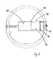
- Fig. 4 is a sectional view taken along the line AA in Fig. 1 shown with lid 4 open.
- Fig. 6 the motor 26 and the planetary gear 28 are formed, which together form the drive 16.
- the planetary gear 28 it is possible to reduce the higher speeds of a commercial electric motor to a speed level that fits the specific application. So an opening time of 1 s to 5 s would be completely sufficient.
- the planetary gear 28 in the drive 16 can be dispensed with.
- the drive 16 is installed in a sleeve 30, which can be easily inserted into a recess 32 provided for receiving the sleeve 30. As a result, the assembly is simplified, and even in case of repair, it is easy to replace a defective drive for a spare part.
- Fig. 6 It can be seen that the lid 4 is rotatably supported on the drive 16 via a movable bearing 34.
- the drive 16 is connected on its fan tube wall facing the end in a fixed bearing 36 with the frame part 6. Due to the fixed arrangement of the wall-side end of the drive 16 can be provided there with drawing not shown connecting elements for a power supply of the drive 16 such as sockets.
- the invention is not limited to the above embodiment.
- the person skilled in the art is capable of adapting the principle of the invention in a manner which seems suitable to him by means of modifications to a specific application.
Landscapes
- Engineering & Computer Science (AREA)
- Chemical & Material Sciences (AREA)
- Combustion & Propulsion (AREA)
- Mechanical Engineering (AREA)
- General Engineering & Computer Science (AREA)
- Fluid Mechanics (AREA)
- Physics & Mathematics (AREA)
- Structures Of Non-Positive Displacement Pumps (AREA)
- Ventilation (AREA)
- Apparatus Associated With Microorganisms And Enzymes (AREA)
- Crushing And Grinding (AREA)
- Air-Flow Control Members (AREA)
- Closing Of Containers (AREA)
- Power-Operated Mechanisms For Wings (AREA)
- Lining Or Joining Of Plastics Or The Like (AREA)
- Refuse Collection And Transfer (AREA)
Priority Applications (4)
| Application Number | Priority Date | Filing Date | Title |
|---|---|---|---|
| PL08001188T PL2031319T3 (pl) | 2007-08-27 | 2008-01-23 | Skrzynia murowa z klapą uruchamianą silnikiem |
| PL08016497T PL2096368T3 (pl) | 2007-08-27 | 2008-09-18 | Urządzenie i sposób sterowania włączeniem i wyłączeniem silnika klapy zależnie od wielkości prądu |
| EP08016497A EP2096368B1 (fr) | 2007-08-27 | 2008-09-18 | Dispositif et procédé d'allumage et d'arrêt d'un moteur à clapets à base d'un capteur de courant |
| ES08016497T ES2393254T3 (es) | 2007-08-27 | 2008-09-18 | Dispositivo y procedimiento para la conexión y desconexión controladas por la corriente de un motor de trampilla |
Applications Claiming Priority (1)
| Application Number | Priority Date | Filing Date | Title |
|---|---|---|---|
| DE102007040632A DE102007040632A1 (de) | 2007-08-27 | 2007-08-27 | Mauerkasten |
Publications (2)
| Publication Number | Publication Date |
|---|---|
| EP2031319A1 true EP2031319A1 (fr) | 2009-03-04 |
| EP2031319B1 EP2031319B1 (fr) | 2010-12-01 |
Family
ID=40083559
Family Applications (2)
| Application Number | Title | Priority Date | Filing Date |
|---|---|---|---|
| EP08001188A Active EP2031319B1 (fr) | 2007-08-27 | 2008-01-23 | Boîtier mural avec clapet motorisé |
| EP08016497A Active EP2096368B1 (fr) | 2007-08-27 | 2008-09-18 | Dispositif et procédé d'allumage et d'arrêt d'un moteur à clapets à base d'un capteur de courant |
Family Applications After (1)
| Application Number | Title | Priority Date | Filing Date |
|---|---|---|---|
| EP08016497A Active EP2096368B1 (fr) | 2007-08-27 | 2008-09-18 | Dispositif et procédé d'allumage et d'arrêt d'un moteur à clapets à base d'un capteur de courant |
Country Status (5)
| Country | Link |
|---|---|
| EP (2) | EP2031319B1 (fr) |
| AT (1) | ATE490442T1 (fr) |
| DE (2) | DE102007040632A1 (fr) |
| ES (2) | ES2356580T3 (fr) |
| PL (2) | PL2031319T3 (fr) |
Cited By (4)
| Publication number | Priority date | Publication date | Assignee | Title |
|---|---|---|---|---|
| WO2011032863A1 (fr) * | 2009-09-17 | 2011-03-24 | Matthias Weibel | Dispositif de verrouillage pour un passage de ventilation dans une paroi d'immeuble |
| FR2952113A1 (fr) * | 2009-11-04 | 2011-05-06 | Aldes Aeraulique | Dispositif de fermeture d'un volet dispose dans un circuit aeraulique |
| GB2497356A (en) * | 2011-12-09 | 2013-06-12 | Greenwood Air Man Ltd | Fan with multi-position grille |
| EP2489914A3 (fr) * | 2011-02-18 | 2014-08-20 | CB-tec GmbH | Traversée de mur pour arrivée d'air |
Families Citing this family (3)
| Publication number | Priority date | Publication date | Assignee | Title |
|---|---|---|---|---|
| DE102014113615B4 (de) | 2014-09-22 | 2018-09-20 | Hanon Systems | Klappe für ein Klimagerät |
| CN107152763B (zh) * | 2017-05-27 | 2019-10-01 | 青岛海尔空调器有限总公司 | 带有净化功能的空调器及其控制方法 |
| DE102021115775A1 (de) | 2021-06-18 | 2022-12-22 | Matthias Weibel | Steuereinrichtung für eine Absperrvorrichtung |
Citations (7)
| Publication number | Priority date | Publication date | Assignee | Title |
|---|---|---|---|---|
| US4372197A (en) | 1980-11-14 | 1983-02-08 | Acme Engineering & Manufacturing Corporation | Cold weather inlet for ventilating systems |
| DE19719991A1 (de) * | 1997-05-13 | 1998-11-19 | Mannesmann Vdo Ag | Lastverstelleinrichtung |
| DE10024691A1 (de) * | 2000-05-18 | 2001-11-22 | Behr Gmbh & Co | Klappe für einen Luftführungskanal |
| DE10024692A1 (de) | 2000-05-18 | 2001-11-29 | Behr Gmbh & Co | Steuereinrichtung für Gasströme |
| EP1223386A2 (fr) * | 2001-01-16 | 2002-07-17 | BSH Bosch und Siemens Hausgeräte GmbH | Procédé et dispositif de commande et/ou de régulation d'une hotte aspirante. |
| EP1366316A1 (fr) * | 2001-03-03 | 2003-12-03 | Oechsler Aktiengesellschaft | Clapet actionne par un moteur |
| DE202005010912U1 (de) | 2005-07-12 | 2005-11-10 | Berbel Ablufttechnik Gmbh | Luftführungskasten |
Family Cites Families (8)
| Publication number | Priority date | Publication date | Assignee | Title |
|---|---|---|---|---|
| US4432272A (en) * | 1982-11-29 | 1984-02-21 | Ruskin Manufacturing Company | Motor operated fire damper |
| DE3332908A1 (de) * | 1983-09-13 | 1985-03-21 | Bernd Dipl.-Ing. Dr. 4410 Warendorf Heiland | Sklaven-schalter |
| DE4411935C1 (de) * | 1994-04-07 | 1995-04-20 | Daimler Benz Ag | Stellantriebseinrichtung |
| US7033268B2 (en) * | 2003-04-17 | 2006-04-25 | Siemens Building Technologies, Inc. | Multi-mode damper actuator |
| JP2006189234A (ja) * | 2005-01-05 | 2006-07-20 | Howa:Kk | 自然換気装置 |
| KR100518762B1 (ko) * | 2005-02-17 | 2005-09-30 | 주식회사 제일테크 | 공동주택용 건식 에어덕트의 배기조절차단판 개폐장치 |
| DE202006006327U1 (de) | 2006-04-19 | 2006-08-24 | Berbel Ablufttechnik Gmbh | Mauerkasten |
| DE102006053280A1 (de) * | 2006-11-02 | 2008-05-08 | PEARL Buisness Connect Import/Export Geschäftskontakte GmbH | Mehrfachsteckdose |
-
2007
- 2007-08-27 DE DE102007040632A patent/DE102007040632A1/de not_active Withdrawn
-
2008
- 2008-01-23 EP EP08001188A patent/EP2031319B1/fr active Active
- 2008-01-23 AT AT08001188T patent/ATE490442T1/de active
- 2008-01-23 PL PL08001188T patent/PL2031319T3/pl unknown
- 2008-01-23 DE DE502008001925T patent/DE502008001925D1/de active Active
- 2008-01-23 ES ES08001188T patent/ES2356580T3/es active Active
- 2008-09-18 ES ES08016497T patent/ES2393254T3/es active Active
- 2008-09-18 EP EP08016497A patent/EP2096368B1/fr active Active
- 2008-09-18 PL PL08016497T patent/PL2096368T3/pl unknown
Patent Citations (7)
| Publication number | Priority date | Publication date | Assignee | Title |
|---|---|---|---|---|
| US4372197A (en) | 1980-11-14 | 1983-02-08 | Acme Engineering & Manufacturing Corporation | Cold weather inlet for ventilating systems |
| DE19719991A1 (de) * | 1997-05-13 | 1998-11-19 | Mannesmann Vdo Ag | Lastverstelleinrichtung |
| DE10024691A1 (de) * | 2000-05-18 | 2001-11-22 | Behr Gmbh & Co | Klappe für einen Luftführungskanal |
| DE10024692A1 (de) | 2000-05-18 | 2001-11-29 | Behr Gmbh & Co | Steuereinrichtung für Gasströme |
| EP1223386A2 (fr) * | 2001-01-16 | 2002-07-17 | BSH Bosch und Siemens Hausgeräte GmbH | Procédé et dispositif de commande et/ou de régulation d'une hotte aspirante. |
| EP1366316A1 (fr) * | 2001-03-03 | 2003-12-03 | Oechsler Aktiengesellschaft | Clapet actionne par un moteur |
| DE202005010912U1 (de) | 2005-07-12 | 2005-11-10 | Berbel Ablufttechnik Gmbh | Luftführungskasten |
Cited By (7)
| Publication number | Priority date | Publication date | Assignee | Title |
|---|---|---|---|---|
| WO2011032863A1 (fr) * | 2009-09-17 | 2011-03-24 | Matthias Weibel | Dispositif de verrouillage pour un passage de ventilation dans une paroi d'immeuble |
| DE112010003695B4 (de) * | 2009-09-17 | 2020-12-10 | Matthias Weibel | Absperrvorrichtung für eine lüftungsdurchbrechung in einer gebäudewand |
| FR2952113A1 (fr) * | 2009-11-04 | 2011-05-06 | Aldes Aeraulique | Dispositif de fermeture d'un volet dispose dans un circuit aeraulique |
| EP2320153A1 (fr) | 2009-11-04 | 2011-05-11 | Aldes Aeraulique | Dispositif de fermeture d'un volet disposé dans un circuit aéraulique |
| EP2489914A3 (fr) * | 2011-02-18 | 2014-08-20 | CB-tec GmbH | Traversée de mur pour arrivée d'air |
| GB2497356A (en) * | 2011-12-09 | 2013-06-12 | Greenwood Air Man Ltd | Fan with multi-position grille |
| GB2497356B (en) * | 2011-12-09 | 2016-06-01 | Greenwood Air Man Ltd | Fan with multi-position grille |
Also Published As
| Publication number | Publication date |
|---|---|
| EP2096368B1 (fr) | 2012-08-15 |
| PL2096368T3 (pl) | 2012-12-31 |
| EP2031319B1 (fr) | 2010-12-01 |
| ES2393254T3 (es) | 2012-12-19 |
| DE502008001925D1 (de) | 2011-01-13 |
| ES2356580T3 (es) | 2011-04-11 |
| ATE490442T1 (de) | 2010-12-15 |
| EP2096368A1 (fr) | 2009-09-02 |
| PL2031319T3 (pl) | 2011-04-29 |
| DE102007040632A1 (de) | 2009-03-05 |
Similar Documents
| Publication | Publication Date | Title |
|---|---|---|
| EP2031319B1 (fr) | Boîtier mural avec clapet motorisé | |
| EP1902258B1 (fr) | Caisson de guidage d'air | |
| EP1921394A1 (fr) | Boîtier mural avec ouverture du clapet à l'aide de pression différentielle d'air | |
| DE102012101175B4 (de) | Drosseleinrichtung für den Luftdurchsatz durch einen Lufteinlass | |
| EP1255932B1 (fr) | Convertisseur d'energie eolienne sur toitures, pour la production d'energie | |
| EP2290298B1 (fr) | hotte d'aspiration avec dispositif de déviation d'un flux d'air | |
| DE3602120C2 (fr) | ||
| DE2232482C2 (de) | Lüftungsanlage | |
| DE112010003695B4 (de) | Absperrvorrichtung für eine lüftungsdurchbrechung in einer gebäudewand | |
| EP2789921B1 (fr) | Hotte aspirante | |
| EP1832450B1 (fr) | Agencement de clapets, notamment pour véhicule automobile | |
| DE19733052A1 (de) | Lufteintritt für eine Heizungs- oder Klimaanlage eines Kraftfahrzeuges | |
| DE19728713C2 (de) | Spritzwassergeschützter elektromotorischer Beschlag | |
| DE10145785A1 (de) | Drehzahlregelung einer ummantelten Windkraftturbine | |
| DE102010047489A1 (de) | Wandeinbaugebläse | |
| DE3003930A1 (de) | Ausgangsweiche einer dunstabzugshaube | |
| DE2615724A1 (de) | Klappenverschluss fuer luefter oder dergleichen | |
| DE202006018971U1 (de) | Vorrichtung zum Klimatisieren von Gebäuden | |
| DE10013689A1 (de) | Lüftungsvorrichtung | |
| CH699248A2 (de) | Jalousie für Kraftfahrzeuge. | |
| EP1101896B1 (fr) | Fenêtre à lamelles | |
| AT403956B (de) | Luftregelklappe für lüftungsgeräte | |
| AT392694B (de) | Waermetauschersystem mit einem querstromluefter | |
| DE1454593A1 (de) | Zwangslueftungsvorrichtung fuer Raeume,insbesondere fuer Wohn- und Arbeitsraeume | |
| DE19700691A1 (de) | Falttor |
Legal Events
| Date | Code | Title | Description |
|---|---|---|---|
| PUAI | Public reference made under article 153(3) epc to a published international application that has entered the european phase |
Free format text: ORIGINAL CODE: 0009012 |
|
| AK | Designated contracting states |
Kind code of ref document: A1 Designated state(s): AT BE BG CH CY CZ DE DK EE ES FI FR GB GR HR HU IE IS IT LI LT LU LV MC MT NL NO PL PT RO SE SI SK TR |
|
| AX | Request for extension of the european patent |
Extension state: AL BA MK RS |
|
| 17Q | First examination report despatched |
Effective date: 20090930 |
|
| 17P | Request for examination filed |
Effective date: 20090901 |
|
| AKX | Designation fees paid |
Designated state(s): AT BE BG CH CY CZ DE DK EE ES FI FR GB GR HR HU IE IS IT LI LT LU LV MC MT NL NO PL PT RO SE SI SK TR |
|
| GRAP | Despatch of communication of intention to grant a patent |
Free format text: ORIGINAL CODE: EPIDOSNIGR1 |
|
| GRAS | Grant fee paid |
Free format text: ORIGINAL CODE: EPIDOSNIGR3 |
|
| GRAA | (expected) grant |
Free format text: ORIGINAL CODE: 0009210 |
|
| AK | Designated contracting states |
Kind code of ref document: B1 Designated state(s): AT BE BG CH CY CZ DE DK EE ES FI FR GB GR HR HU IE IS IT LI LT LU LV MC MT NL NO PL PT RO SE SI SK TR |
|
| REG | Reference to a national code |
Ref country code: GB Ref legal event code: FG4D Free format text: NOT ENGLISH |
|
| REG | Reference to a national code |
Ref country code: CH Ref legal event code: EP |
|
| REG | Reference to a national code |
Ref country code: IE Ref legal event code: FG4D |
|
| REF | Corresponds to: |
Ref document number: 502008001925 Country of ref document: DE Date of ref document: 20110113 Kind code of ref document: P |
|
| REG | Reference to a national code |
Ref country code: CH Ref legal event code: NV Representative=s name: ISLER & PEDRAZZINI AG |
|
| REG | Reference to a national code |
Ref country code: NL Ref legal event code: T3 |
|
| REG | Reference to a national code |
Ref country code: ES Ref legal event code: FG2A Ref document number: 2356580 Country of ref document: ES Kind code of ref document: T3 Effective date: 20110411 |
|
| PG25 | Lapsed in a contracting state [announced via postgrant information from national office to epo] |
Ref country code: NO Free format text: LAPSE BECAUSE OF FAILURE TO SUBMIT A TRANSLATION OF THE DESCRIPTION OR TO PAY THE FEE WITHIN THE PRESCRIBED TIME-LIMIT Effective date: 20110301 Ref country code: LT Free format text: LAPSE BECAUSE OF FAILURE TO SUBMIT A TRANSLATION OF THE DESCRIPTION OR TO PAY THE FEE WITHIN THE PRESCRIBED TIME-LIMIT Effective date: 20101201 |
|
| REG | Reference to a national code |
Ref country code: PL Ref legal event code: T3 |
|
| REG | Reference to a national code |
Ref country code: SK Ref legal event code: T3 Ref document number: E 8841 Country of ref document: SK |
|
| LTIE | Lt: invalidation of european patent or patent extension |
Effective date: 20101201 |
|
| PG25 | Lapsed in a contracting state [announced via postgrant information from national office to epo] |
Ref country code: SI Free format text: LAPSE BECAUSE OF FAILURE TO SUBMIT A TRANSLATION OF THE DESCRIPTION OR TO PAY THE FEE WITHIN THE PRESCRIBED TIME-LIMIT Effective date: 20101201 Ref country code: CY Free format text: LAPSE BECAUSE OF FAILURE TO SUBMIT A TRANSLATION OF THE DESCRIPTION OR TO PAY THE FEE WITHIN THE PRESCRIBED TIME-LIMIT Effective date: 20101201 Ref country code: LV Free format text: LAPSE BECAUSE OF FAILURE TO SUBMIT A TRANSLATION OF THE DESCRIPTION OR TO PAY THE FEE WITHIN THE PRESCRIBED TIME-LIMIT Effective date: 20101201 Ref country code: HR Free format text: LAPSE BECAUSE OF FAILURE TO SUBMIT A TRANSLATION OF THE DESCRIPTION OR TO PAY THE FEE WITHIN THE PRESCRIBED TIME-LIMIT Effective date: 20101201 Ref country code: FI Free format text: LAPSE BECAUSE OF FAILURE TO SUBMIT A TRANSLATION OF THE DESCRIPTION OR TO PAY THE FEE WITHIN THE PRESCRIBED TIME-LIMIT Effective date: 20101201 Ref country code: SE Free format text: LAPSE BECAUSE OF FAILURE TO SUBMIT A TRANSLATION OF THE DESCRIPTION OR TO PAY THE FEE WITHIN THE PRESCRIBED TIME-LIMIT Effective date: 20101201 Ref country code: BG Free format text: LAPSE BECAUSE OF FAILURE TO SUBMIT A TRANSLATION OF THE DESCRIPTION OR TO PAY THE FEE WITHIN THE PRESCRIBED TIME-LIMIT Effective date: 20110301 |
|
| REG | Reference to a national code |
Ref country code: IE Ref legal event code: FD4D |
|
| PG25 | Lapsed in a contracting state [announced via postgrant information from national office to epo] |
Ref country code: GR Free format text: LAPSE BECAUSE OF FAILURE TO SUBMIT A TRANSLATION OF THE DESCRIPTION OR TO PAY THE FEE WITHIN THE PRESCRIBED TIME-LIMIT Effective date: 20110302 |
|
| REG | Reference to a national code |
Ref country code: HU Ref legal event code: AG4A Ref document number: E010517 Country of ref document: HU |
|
| PG25 | Lapsed in a contracting state [announced via postgrant information from national office to epo] |
Ref country code: EE Free format text: LAPSE BECAUSE OF FAILURE TO SUBMIT A TRANSLATION OF THE DESCRIPTION OR TO PAY THE FEE WITHIN THE PRESCRIBED TIME-LIMIT Effective date: 20101201 Ref country code: IE Free format text: LAPSE BECAUSE OF FAILURE TO SUBMIT A TRANSLATION OF THE DESCRIPTION OR TO PAY THE FEE WITHIN THE PRESCRIBED TIME-LIMIT Effective date: 20101201 Ref country code: IS Free format text: LAPSE BECAUSE OF FAILURE TO SUBMIT A TRANSLATION OF THE DESCRIPTION OR TO PAY THE FEE WITHIN THE PRESCRIBED TIME-LIMIT Effective date: 20110401 Ref country code: PT Free format text: LAPSE BECAUSE OF FAILURE TO SUBMIT A TRANSLATION OF THE DESCRIPTION OR TO PAY THE FEE WITHIN THE PRESCRIBED TIME-LIMIT Effective date: 20110401 |
|
| BERE | Be: lapsed |
Owner name: OZPOLAT, ILGAZ Effective date: 20110131 |
|
| PG25 | Lapsed in a contracting state [announced via postgrant information from national office to epo] |
Ref country code: MC Free format text: LAPSE BECAUSE OF NON-PAYMENT OF DUE FEES Effective date: 20110131 Ref country code: RO Free format text: LAPSE BECAUSE OF FAILURE TO SUBMIT A TRANSLATION OF THE DESCRIPTION OR TO PAY THE FEE WITHIN THE PRESCRIBED TIME-LIMIT Effective date: 20101201 |
|
| PLBE | No opposition filed within time limit |
Free format text: ORIGINAL CODE: 0009261 |
|
| STAA | Information on the status of an ep patent application or granted ep patent |
Free format text: STATUS: NO OPPOSITION FILED WITHIN TIME LIMIT |
|
| REG | Reference to a national code |
Ref country code: FR Ref legal event code: ST Effective date: 20110930 |
|
| PG25 | Lapsed in a contracting state [announced via postgrant information from national office to epo] |
Ref country code: FR Free format text: LAPSE BECAUSE OF NON-PAYMENT OF DUE FEES Effective date: 20110201 Ref country code: DK Free format text: LAPSE BECAUSE OF FAILURE TO SUBMIT A TRANSLATION OF THE DESCRIPTION OR TO PAY THE FEE WITHIN THE PRESCRIBED TIME-LIMIT Effective date: 20101201 |
|
| 26N | No opposition filed |
Effective date: 20110902 |
|
| PG25 | Lapsed in a contracting state [announced via postgrant information from national office to epo] |
Ref country code: BE Free format text: LAPSE BECAUSE OF NON-PAYMENT OF DUE FEES Effective date: 20110131 |
|
| REG | Reference to a national code |
Ref country code: DE Ref legal event code: R097 Ref document number: 502008001925 Country of ref document: DE Effective date: 20110902 |
|
| PG25 | Lapsed in a contracting state [announced via postgrant information from national office to epo] |
Ref country code: MT Free format text: LAPSE BECAUSE OF FAILURE TO SUBMIT A TRANSLATION OF THE DESCRIPTION OR TO PAY THE FEE WITHIN THE PRESCRIBED TIME-LIMIT Effective date: 20101201 |
|
| PG25 | Lapsed in a contracting state [announced via postgrant information from national office to epo] |
Ref country code: LU Free format text: LAPSE BECAUSE OF NON-PAYMENT OF DUE FEES Effective date: 20110123 |
|
| PGFP | Annual fee paid to national office [announced via postgrant information from national office to epo] |
Ref country code: TR Payment date: 20230123 Year of fee payment: 16 Ref country code: IT Payment date: 20230120 Year of fee payment: 16 |
|
| PGFP | Annual fee paid to national office [announced via postgrant information from national office to epo] |
Ref country code: PL Payment date: 20231220 Year of fee payment: 17 Ref country code: NL Payment date: 20240119 Year of fee payment: 17 |
|
| PGFP | Annual fee paid to national office [announced via postgrant information from national office to epo] |
Ref country code: ES Payment date: 20240223 Year of fee payment: 17 |
|
| PGFP | Annual fee paid to national office [announced via postgrant information from national office to epo] |
Ref country code: AT Payment date: 20240122 Year of fee payment: 17 |
|
| PGFP | Annual fee paid to national office [announced via postgrant information from national office to epo] |
Ref country code: HU Payment date: 20240123 Year of fee payment: 17 Ref country code: DE Payment date: 20240115 Year of fee payment: 17 Ref country code: CZ Payment date: 20240115 Year of fee payment: 17 Ref country code: GB Payment date: 20240119 Year of fee payment: 17 Ref country code: CH Payment date: 20240202 Year of fee payment: 17 Ref country code: SK Payment date: 20240115 Year of fee payment: 17 |