EP1832450B1 - Agencement de clapets, notamment pour véhicule automobile - Google Patents
Agencement de clapets, notamment pour véhicule automobile Download PDFInfo
- Publication number
- EP1832450B1 EP1832450B1 EP20060290390 EP06290390A EP1832450B1 EP 1832450 B1 EP1832450 B1 EP 1832450B1 EP 20060290390 EP20060290390 EP 20060290390 EP 06290390 A EP06290390 A EP 06290390A EP 1832450 B1 EP1832450 B1 EP 1832450B1
- Authority
- EP
- European Patent Office
- Prior art keywords
- flap
- assembly according
- valve
- valve flap
- flaps
- Prior art date
- Legal status (The legal status is an assumption and is not a legal conclusion. Google has not performed a legal analysis and makes no representation as to the accuracy of the status listed.)
- Expired - Fee Related
Links
Images

Classifications
-
- F—MECHANICAL ENGINEERING; LIGHTING; HEATING; WEAPONS; BLASTING
- F16—ENGINEERING ELEMENTS AND UNITS; GENERAL MEASURES FOR PRODUCING AND MAINTAINING EFFECTIVE FUNCTIONING OF MACHINES OR INSTALLATIONS; THERMAL INSULATION IN GENERAL
- F16K—VALVES; TAPS; COCKS; ACTUATING-FLOATS; DEVICES FOR VENTING OR AERATING
- F16K1/00—Lift valves or globe valves, i.e. cut-off apparatus with closure members having at least a component of their opening and closing motion perpendicular to the closing faces
- F16K1/16—Lift valves or globe valves, i.e. cut-off apparatus with closure members having at least a component of their opening and closing motion perpendicular to the closing faces with pivoted closure-members
- F16K1/18—Lift valves or globe valves, i.e. cut-off apparatus with closure members having at least a component of their opening and closing motion perpendicular to the closing faces with pivoted closure-members with pivoted discs or flaps
- F16K1/22—Lift valves or globe valves, i.e. cut-off apparatus with closure members having at least a component of their opening and closing motion perpendicular to the closing faces with pivoted closure-members with pivoted discs or flaps with axis of rotation crossing the valve member, e.g. butterfly valves
- F16K1/223—Lift valves or globe valves, i.e. cut-off apparatus with closure members having at least a component of their opening and closing motion perpendicular to the closing faces with pivoted closure-members with pivoted discs or flaps with axis of rotation crossing the valve member, e.g. butterfly valves with a plurality of valve members
-
- B—PERFORMING OPERATIONS; TRANSPORTING
- B60—VEHICLES IN GENERAL
- B60H—ARRANGEMENTS OF HEATING, COOLING, VENTILATING OR OTHER AIR-TREATING DEVICES SPECIALLY ADAPTED FOR PASSENGER OR GOODS SPACES OF VEHICLES
- B60H1/00—Heating, cooling or ventilating [HVAC] devices
- B60H1/00642—Control systems or circuits; Control members or indication devices for heating, cooling or ventilating devices
- B60H1/00664—Construction or arrangement of damper doors
- B60H1/00671—Damper doors moved by rotation; Grilles
- B60H1/00678—Damper doors moved by rotation; Grilles the axis of rotation being in the door plane, e.g. butterfly doors
-
- B—PERFORMING OPERATIONS; TRANSPORTING
- B60—VEHICLES IN GENERAL
- B60H—ARRANGEMENTS OF HEATING, COOLING, VENTILATING OR OTHER AIR-TREATING DEVICES SPECIALLY ADAPTED FOR PASSENGER OR GOODS SPACES OF VEHICLES
- B60H1/00—Heating, cooling or ventilating [HVAC] devices
- B60H1/00642—Control systems or circuits; Control members or indication devices for heating, cooling or ventilating devices
- B60H1/00814—Control systems or circuits characterised by their output, for controlling particular components of the heating, cooling or ventilating installation
- B60H1/00821—Control systems or circuits characterised by their output, for controlling particular components of the heating, cooling or ventilating installation the components being ventilating, air admitting or air distributing devices
- B60H1/00835—Damper doors, e.g. position control
- B60H1/00842—Damper doors, e.g. position control the system comprising a plurality of damper doors; Air distribution between several outlets
Definitions
- the invention relates to a flap arrangement, in particular for a motor vehicle, according to the preamble of claim 1.
- Flaps such as in particular butterfly flaps or flaps with a laterally arranged pivot axis usually have a certain spring travel in the direction of rotation, which is proportional to the distance from the pivot axis and the flap rotation. Such a flap leaves nothing to be desired.
- a double flap assembly of an air conditioning system of a motor vehicle which has a main flap with an opening that can be covered by a smaller flap. Both the main flap and the inner flap are arranged coaxially on a rotation axis.
- a flap arrangement in particular for a motor vehicle, the flap arrangement, in particular for a Motor vehicle, comprising at least two operable in response to flaps, provided, wherein the two flaps are arranged concentrically with each other with a common pivot axis, the second flap having an opening in the region of the pivot axis, and the first flap all or at least with a substantial part of its flap surface Within or within the opening of the second, outer flap is arranged. Overlapping of the two flaps can be provided in the edge regions. The overlaps serve in particular the sealing of the two flaps against each other in the closed flap position.
- the flap arrangement preferably regulates the passage of air, but in principle it can also be used for other media, possibly also liquids.
- the two flaps on a single drive shaft by an actuator, such as. A stepper motor, operated. As a result of the present fixed coupling of the two flaps begin and end the actuating movements of the two flaps simultaneously.
- Such a flap arrangement offers particular advantages, also with regard to a good air flow, when the entry plane is offset with respect to the exit plane.
- the inner flap In the closed position of the inner flap is preferably the inner flap on the outer flap, for which preferably contact areas or contact surfaces on at least one of the two flaps are designed accordingly to ensure adequate sealing of the flaps against each other.
- the sealing effect is achieved by a circumferential Edge, possibly made of a softer, elastic material, supported.
- the outer flap is preferably in its closed position to a housing, wherein the housing is preferably part of the flap assembly, so that the pre-assembly of the flaps is simplified and only the housing must be installed in another housing or attached to another housing.
- the outer flap is mounted directly on the shaft of the inner flap, whereby a very compact design is possible.
- the inner flap preferably undergoes a faster pivoting movement than the outer flap, i. the adjusting movement takes place with a larger swinging speed, but the adjusting movements preferably begin and end simultaneously.
- the inner flap has a larger swing angle than the outer flap.
- the inner flap is preferably a butterfly flap, with the wing lengths of the two sides preferably being equal. Particularly preferred is a point-symmetrical configuration with respect to the pivot axis.
- the outer flap is preferably a butterfly flap with an opening in the inner area. Particularly preferred is a point-symmetrical configuration with respect to the pivot axis.
- the opening in the outer flap preferably has a rectangular shape, wherein the opening is preferably slightly smaller than the inner flap, so that a sufficient coverage for tight installation is ensured.
- a gear arrangement with two gears is provided.
- the transmissions are preferably gear transmissions.
- the two gears are drive side, i. motor side, rigidly coupled together. This can be done for example by the formation of two gears on the motor shaft.
- the two gears preferably have different ratios, whereby the different actuating movements are effected.
- the ratio of the transmission of the inner flap is preferably greater than the ratio of the transmission of the outer flap.
- the adjusting movements of the two flaps are preferably in a linear relationship to each other. Particularly preferred are ratios of the adjusting movement of the inner flap for adjusting the outer flap of 1.5: 1 to 5: 1, in particular from 2: 1 to 4: 1 and most preferably from about 3: 1.
- the adjusting movement of the inner flap is preferably a maximum of 80 ° to 100 °, a maximum of 85 ° to 95 °, and particularly preferably a maximum of 90 °.
- the adjusting movement of the outer flap is preferably a maximum of 20 ° to 40 °, a maximum of 25 ° to 35 ° and particularly preferably a maximum of 30 °.
- the flap arrangement according to the invention is arranged in an air duct area which has an S-shaped offset, wherein the maximum opening angle of the outer flap in its orientation corresponds to the mean course of the air duct in the oblique area, and the maximum opening angle of the inner flap in its orientation corresponds to the mean course of the air duct in the inlet and / or outlet area.
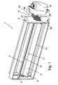
- a flap assembly 1 is disposed in an air passage of a motor vehicle ventilation system.
- the flap assembly 1 has a housing 2 with a continuous, the corresponding part of the air channel forming opening with a substantially constant flow cross-section, two with respect to their pivotal area concentrically arranged flaps 3 and 4 with a pivot axis 5 and a gear assembly 6.
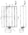
- the course of the opening forming the corresponding region of the air duct is formed approximately S-shaped according to the present exemplary embodiment, ie the air flow is additionally deflected in the area of the flap arrangement 1, the width of the air duct being over the entire length the opening is constant.
- the height of the air duct increases slightly in the flow direction, with, as, out Fig. 5 can be seen, the entry level E1 is on average above the means of the exit plane E2 and the two planes are arranged parallel to each other.
- the pivot axis 5 of the two flaps 3 and 4 is parallel to the two previously mentioned planes E1, E2, wherein it is arranged centrally with respect to the height of the air duct forming opening in the corresponding cross section which is parallel to the two planes E1, E2.
- inner flap 3 Trained as a plastic injection molded part, inner flap 3 has a shaft 7, which extends over the entire width of the opening of the air duct and end is mounted by means of a respective pin 8 in corresponding bearings in the housing 2. Integral with the shaft 7, the approximately butterfly-shaped flap surface 9 is formed, wherein the two substantially flat-shaped wing sides are slightly offset in the opening direction to each other. Here, the flap surface 9 in the direction of the pivot axis 5 is smaller than the total width of the opening of the air duct. At each of the flap surfaces 9 a pointing in the closing direction edge 10 is formed. It can be made according to a variant of the embodiment in the two-component injection molding process and consist of a softer, elastic plastic, so that a better seal against the outer flap 4 is possible.
- the pivoting angle of the inner flap 3 is 90 ° according to the present embodiment.
- outer flap 4 is mounted on the shaft 7, in the present case in the region of the pin 8, and thus pivotable relative to the inner flap 3.
- the outer flap 4 has a rectangular, schmetterllngsförmige shape, wherein in the central region an opening 11 is provided, which is slightly smaller than the Flap area 9 of the inner flap 3 is.
- the flap surface 12 extends in its schwenkachsen ingredienten area approximately in a plane, then curves slightly in the opening direction and at the outer end back.
- the flap surface 12 each has a pointing in the closing direction edge 13, wherein at the radially outer end of the edge 13 of both wings approximately in a plane E3 (see Fig.
- This edge 13 serves to seal against the housing 2.
- On the outer sides of the opening 11 is provided on both sides of a relatively narrow web, which has a bearing 14 on the pin 8 of the shaft 7 in the pivot axis. For strength and manufacturing reasons, this area is presently made of a different material (see. Fig. 6 ).
- the edge 13 may also be made in accordance with the variant of the embodiment described above in two-component injection molding and consist of a softer, elastic plastic, so that a better seal against the housing 2 is possible.
- the swivel angle of the outer flap 4 is 30 °, ie it is significantly smaller than the swivel angle of the inner flap 3.
- the maximum open state of the outer flap 4 approximately corresponds in its orientation to the course of the air channel in the oblique part (see FIG Fig. 4b ), while the maximum open state of the inner flap 3 in the present case corresponds horizontally and in its orientation approximately to the course of the air duct before or after the inflow or outflow.
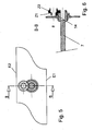
- the gear assembly 6 is formed such that on a motor shaft 16 coming from a motor 15 two gears Z1 and Z2 are formed, which in the present eleven or nineteen teeth and have a different diameter.
- the motor side arranged, larger gear Z2 meshes with a smaller gear Z3, which has approximately the same outer diameter as the gear Z1, and eleven teeth.
- the end, arranged smaller gear Z1 meshes with a larger gear Z4, which has approximately the same outer diameter as the gear Z2, and nineteen teeth.
- the gear Z3 is connected to the inner flap 3, wherein the gear Z3 is formed on the end end of the shaft 7, and the gear Z4 is connected to the outer flap 4, wherein it is arranged on the outside of the bearing 14 (see. Fig. 6 ).
Claims (18)
- Agencement de volets servant à la régulation de l'écoulement de milieux, en particulier pour un véhicule automobile, présentant au moins deux volets (3, 4) pouvant être actionnés indépendamment l'un de l'autre, où les deux volets (3 et 4) comportant un axe de pivotement commun (5) sont disposés de façon concentrique l'un par rapport à l'autre, le deuxième volet (5) présentant une ouverture (11) dans la zone de l'axe de pivotement (5), et le premier volet (3) est disposé, en totalité ou au moins par une partie importante de sa surface de volet (9), à l'intérieur ou principalement à l'intérieur de l'ouverture (11) du deuxième volet extérieur (4),
caractérisé en ce qu'il est prévu un agencement d'engrenages (6) à deux engrenages, pour la transmission des mouvements de réglage d'un actionneur (15), où les deux engrenages sont couplés l'un à l'autre de façon rigide, côté entraînement c'est-à-dire côté moteur. - Agencement de volets selon la revendication 1, caractérisé en ce que le volet intérieur (3), en position fermée, est en appui sur le volet extérieur (4).
- Agencement de volets selon la revendication 1 ou 2, caractérisé en ce que le volet extérieur (4), en position fermée, est en appui sur un carter (2).
- Agencement de volets selon l'une quelconque des revendications précédentes, caractérisé en ce que le volet extérieur (4) est monté sur l'arbre (7) du volet intérieur (3).
- Agencement de volets selon l'une quelconque des revendications précédentes, caractérisé en ce que le volet intérieur (3) effectue un mouvement pivotant plus rapide que le volet extérieur (4).
- Agencement de volets selon l'une quelconque des revendications précédentes, caractérisé en ce que le volet intérieur (3) a un angle de pivotement plus grand que celui du volet extérieur (4).
- Agencement de volets selon l'une quelconque des revendications précédentes, caractérisé en ce que le volet intérieur (3) est un volet papillon.
- Agencement de volets selon l'une quelconque des revendications précédentes, caractérisé en ce que le volet extérieur (4) est un volet papillon comportant une ouverture (11) dans la zone intérieure.
- Agencement de volets selon la revendication 8, caractérisé en ce que l'ouverture (11) présente une forme rectangulaire.
- Agencement de volets selon la revendication 8 ou 9, caractérisé en ce que l'ouverture (11) est un peu plus petite que les dimensions extérieures du volet intérieur (3).
- Agencement de volets selon l'une quelconque des revendications précédentes, caractérisé en ce que chaque engrenage est formé par deux roues dentées (Z1 - Z4 et Z2 - Z3), où l'une des roues dentées (Z1 et Z2) est disposée fixement sur un arbre d'entraînement (16), l'autre roue dentée (Z4 ou Z3) étant disposée fixement sur l'arbre respectif (7) ou sur une zone - montée de façon pivotante - du volet intérieur (3) ou du volet extérieur (4).
- Agencement de volets selon la revendication 11, caractérisé en ce que les roues dentées (Z1 et Z2) sont assemblées fixement l'une à l'autre, sur l'arbre d'entraînement (16), configurées en particulier en formant une seule et même pièce l'une avec l'autre.
- Agencement de volets selon l'une quelconque des revendications précédentes, caractérisé en ce que les deux engrenages présentent des rapports de transmission différents, où le rapport de transmission de l'engrenage du volet intérieur (3) est supérieur au rapport de transmission de l'engrenage du volet extérieur (4).
- Agencement de volets selon l'une quelconque des revendications précédentes, caractérisé en ce que les mouvements de réglage des deux volets (3 et 4) sont dans un rapport linéaire, l'un par rapport à l'autre.
- Agencement de volets selon l'une quelconque des revendications précédentes, caractérisé en ce que les mouvements de réglage des deux volets (3 et 4) sont, l'un par rapport à l'autre, dans un rapport de 1,5 : 1 à 5 : 1, en particulier de 2 : 1 à 4 : 1.
- Agencement de volets selon l'une quelconque des revendications précédentes, caractérisé en ce que le mouvement de réglage du volet intérieur (3) est au maximum de 80° à 100°, en particulier au maximum de 90°.
- Agencement de volets selon l'une quelconque des revendications précédentes, caractérisé en ce que le mouvement de réglage du volet extérieur (4) est au maximum de 20° à 40°, en particulier au maximum de 30°.
- Agencement comprenant un conduit d'air et un agencement de volets selon l'une quelconque des revendications précédentes, caractérisé en ce que l'agencement de volets (1) est disposé dans une zone de conduit d'air qui présente un décalage configuré en forme de S, où l'angle d'ouverture maximum du volet extérieur (4) correspond, dans son orientation, au profil central du conduit d'air dans la zone inclinée, et l'angle d'ouverture maximum du volet intérieur (3) correspond, dans son orientation, au profil central du conduit d'air dans la zone d'entrée et / ou de sortie.
Priority Applications (2)
| Application Number | Priority Date | Filing Date | Title |
|---|---|---|---|
| DE200650006232 DE502006006232D1 (de) | 2006-03-08 | 2006-03-08 | Klappenanordnung, insbesondere für ein Kraftfahrzeug |
| EP20060290390 EP1832450B1 (fr) | 2006-03-08 | 2006-03-08 | Agencement de clapets, notamment pour véhicule automobile |
Applications Claiming Priority (1)
| Application Number | Priority Date | Filing Date | Title |
|---|---|---|---|
| EP20060290390 EP1832450B1 (fr) | 2006-03-08 | 2006-03-08 | Agencement de clapets, notamment pour véhicule automobile |
Publications (2)
| Publication Number | Publication Date |
|---|---|
| EP1832450A1 EP1832450A1 (fr) | 2007-09-12 |
| EP1832450B1 true EP1832450B1 (fr) | 2010-02-24 |
Family
ID=36717000
Family Applications (1)
| Application Number | Title | Priority Date | Filing Date |
|---|---|---|---|
| EP20060290390 Expired - Fee Related EP1832450B1 (fr) | 2006-03-08 | 2006-03-08 | Agencement de clapets, notamment pour véhicule automobile |
Country Status (2)
| Country | Link |
|---|---|
| EP (1) | EP1832450B1 (fr) |
| DE (1) | DE502006006232D1 (fr) |
Families Citing this family (3)
| Publication number | Priority date | Publication date | Assignee | Title |
|---|---|---|---|---|
| KR100935074B1 (ko) | 2008-04-17 | 2009-12-31 | 모딘코리아 유한회사 | 차량용 공기조화장치 |
| DE102008040338B3 (de) | 2008-07-10 | 2010-04-15 | Visteon Global Technologies, Inc., Van Buren Township | Fahrzeugklimaanlage |
| DE102009024255A1 (de) | 2009-06-05 | 2010-12-09 | Behr Gmbh & Co. Kg | Klappenanordnung |
Family Cites Families (4)
| Publication number | Priority date | Publication date | Assignee | Title |
|---|---|---|---|---|
| IT1238134B (it) * | 1989-10-20 | 1993-07-09 | Borletti Climatizzazione | Distributore per impianti di climatizzazione di autoveicoli. |
| US5220944A (en) * | 1992-07-14 | 1993-06-22 | Ford Motor Company | Dual blend door assembly |
| DE19603944C1 (de) * | 1996-02-05 | 1997-02-27 | Daimler Benz Ag | Heizungs- oder Klimaanlage für Fahrzeuginnenräume |
| DE19805883C2 (de) * | 1998-02-13 | 2001-05-10 | Audi Ag | Heiz- bzw. Klimaanlage für Kraftfahrzeuge |
-
2006
- 2006-03-08 DE DE200650006232 patent/DE502006006232D1/de active Active
- 2006-03-08 EP EP20060290390 patent/EP1832450B1/fr not_active Expired - Fee Related
Also Published As
| Publication number | Publication date |
|---|---|
| DE502006006232D1 (de) | 2010-04-08 |
| EP1832450A1 (fr) | 2007-09-12 |
Similar Documents
| Publication | Publication Date | Title |
|---|---|---|
| DE102011113227B4 (de) | Verstopfungsresistente Luftklappe | |
| EP1800918B1 (fr) | Buse d'air à écoulement tourbillonnant | |
| DE102009041532B4 (de) | Dralleinrichtung für einen Luftausströmer | |
| DE102006054041B3 (de) | Regelvorrichtung für eine Verbrennungskraftmaschine | |
| DE102006043647A1 (de) | Klappenventilanordnung mit verbesserter Strömungscharakteristik | |
| EP1577131B1 (fr) | Régulateur de flux servant à réguler le débit de fluide à travers un conduit | |
| DE102013206410A1 (de) | Luftklappenanordnung mit gesondertem Anschlagbauteil | |
| DE102006031028A1 (de) | Betätigungseinrichtung eines Ventils, insbesondere eines Abasrückführventil | |
| WO2012110203A1 (fr) | Agencement de volets d'aération | |
| DE102010060253A1 (de) | Vorrichtung zur Einstellung einer Kühlluftzuströmung | |
| EP3231647A1 (fr) | Dispositif d'écoulement d'air | |
| EP1270286B1 (fr) | Dispositif pour diriger l'air, notamment pour un véhicule | |
| EP1520738B1 (fr) | Aerateur à lamelles, en particulier pour climatisation de véhicule | |
| EP1532011B1 (fr) | Dispositif de commande muni d'un coffret a bande enroulee | |
| EP1832450B1 (fr) | Agencement de clapets, notamment pour véhicule automobile | |
| DE102008057128A1 (de) | Ventileinrichtung zur Steuerung eines von einer Brennkraftmaschine zurückgeführten und zugeführten Abgasstromes | |
| EP1911616B1 (fr) | Tuyère d'air destinée à l'aération d'un espace intérieur de véhicule | |
| WO2011032863A1 (fr) | Dispositif de verrouillage pour un passage de ventilation dans une paroi d'immeuble | |
| EP2233729B1 (fr) | Dispositif de clapets pour un moteur à combustion interne | |
| DE19834575A1 (de) | Drehschieberventil | |
| DE19512874B4 (de) | Drosselklappenstutzen | |
| DE19939212C1 (de) | Heizungs- oder Klimaanlage für Fahrzeuge | |
| WO2007124874A1 (fr) | Fenetre levable | |
| DE102007016184A1 (de) | Klappenanordnung, insbesondere für ein Kraftfahrzeug-Belüftungssystem | |
| EP1516758B1 (fr) | Agencement de clapets d'air |
Legal Events
| Date | Code | Title | Description |
|---|---|---|---|
| PUAI | Public reference made under article 153(3) epc to a published international application that has entered the european phase |
Free format text: ORIGINAL CODE: 0009012 |
|
| AK | Designated contracting states |
Kind code of ref document: A1 Designated state(s): AT BE BG CH CY CZ DE DK EE ES FI FR GB GR HU IE IS IT LI LT LU LV MC NL PL PT RO SE SI SK TR |
|
| AX | Request for extension of the european patent |
Extension state: AL BA HR MK YU |
|
| 17P | Request for examination filed |
Effective date: 20080312 |
|
| 17Q | First examination report despatched |
Effective date: 20080416 |
|
| AKX | Designation fees paid |
Designated state(s): DE FR |
|
| GRAP | Despatch of communication of intention to grant a patent |
Free format text: ORIGINAL CODE: EPIDOSNIGR1 |
|
| GRAS | Grant fee paid |
Free format text: ORIGINAL CODE: EPIDOSNIGR3 |
|
| GRAA | (expected) grant |
Free format text: ORIGINAL CODE: 0009210 |
|
| AK | Designated contracting states |
Kind code of ref document: B1 Designated state(s): DE FR |
|
| REF | Corresponds to: |
Ref document number: 502006006232 Country of ref document: DE Date of ref document: 20100408 Kind code of ref document: P |
|
| PLBE | No opposition filed within time limit |
Free format text: ORIGINAL CODE: 0009261 |
|
| STAA | Information on the status of an ep patent application or granted ep patent |
Free format text: STATUS: NO OPPOSITION FILED WITHIN TIME LIMIT |
|
| 26N | No opposition filed |
Effective date: 20101125 |
|
| REG | Reference to a national code |
Ref country code: DE Ref legal event code: R082 Ref document number: 502006006232 Country of ref document: DE Representative=s name: GRAUEL, ANDREAS, DIPL.-PHYS. DR. RER. NAT., DE Ref country code: DE Ref legal event code: R081 Ref document number: 502006006232 Country of ref document: DE Owner name: MAHLE INTERNATIONAL GMBH, DE Free format text: FORMER OWNER: BEHR FRANCE ROUFFACH S.A.S., ROUFFACH, FR |
|
| REG | Reference to a national code |
Ref country code: FR Ref legal event code: PLFP Year of fee payment: 11 |
|
| REG | Reference to a national code |
Ref country code: FR Ref legal event code: PLFP Year of fee payment: 12 |
|
| REG | Reference to a national code |
Ref country code: FR Ref legal event code: PLFP Year of fee payment: 13 |
|
| PGFP | Annual fee paid to national office [announced via postgrant information from national office to epo] |
Ref country code: DE Payment date: 20190404 Year of fee payment: 14 |
|
| PGFP | Annual fee paid to national office [announced via postgrant information from national office to epo] |
Ref country code: FR Payment date: 20200401 Year of fee payment: 15 |
|
| REG | Reference to a national code |
Ref country code: DE Ref legal event code: R119 Ref document number: 502006006232 Country of ref document: DE |
|
| PG25 | Lapsed in a contracting state [announced via postgrant information from national office to epo] |
Ref country code: DE Free format text: LAPSE BECAUSE OF NON-PAYMENT OF DUE FEES Effective date: 20201001 |
|
| PG25 | Lapsed in a contracting state [announced via postgrant information from national office to epo] |
Ref country code: FR Free format text: LAPSE BECAUSE OF NON-PAYMENT OF DUE FEES Effective date: 20210331 |