EP2027386B1 - Einspritzinjektor für brennkraftmaschinen - Google Patents
Einspritzinjektor für brennkraftmaschinen Download PDFInfo
- Publication number
- EP2027386B1 EP2027386B1 EP07764607A EP07764607A EP2027386B1 EP 2027386 B1 EP2027386 B1 EP 2027386B1 EP 07764607 A EP07764607 A EP 07764607A EP 07764607 A EP07764607 A EP 07764607A EP 2027386 B1 EP2027386 B1 EP 2027386B1
- Authority
- EP
- European Patent Office
- Prior art keywords
- injector according
- filter
- support sleeve
- sleeve
- injector
- Prior art date
- Legal status (The legal status is an assumption and is not a legal conclusion. Google has not performed a legal analysis and makes no representation as to the accuracy of the status listed.)
- Active
Links
Images
Classifications
-
- F—MECHANICAL ENGINEERING; LIGHTING; HEATING; WEAPONS; BLASTING
- F02—COMBUSTION ENGINES; HOT-GAS OR COMBUSTION-PRODUCT ENGINE PLANTS
- F02M—SUPPLYING COMBUSTION ENGINES IN GENERAL WITH COMBUSTIBLE MIXTURES OR CONSTITUENTS THEREOF
- F02M61/00—Fuel-injectors not provided for in groups F02M39/00 - F02M57/00 or F02M67/00
- F02M61/16—Details not provided for in, or of interest apart from, the apparatus of groups F02M61/02 - F02M61/14
- F02M61/165—Filtering elements specially adapted in fuel inlets to injector
-
- F—MECHANICAL ENGINEERING; LIGHTING; HEATING; WEAPONS; BLASTING
- F02—COMBUSTION ENGINES; HOT-GAS OR COMBUSTION-PRODUCT ENGINE PLANTS
- F02M—SUPPLYING COMBUSTION ENGINES IN GENERAL WITH COMBUSTIBLE MIXTURES OR CONSTITUENTS THEREOF
- F02M47/00—Fuel-injection apparatus operated cyclically with fuel-injection valves actuated by fluid pressure
- F02M47/02—Fuel-injection apparatus operated cyclically with fuel-injection valves actuated by fluid pressure of accumulator-injector type, i.e. having fuel pressure of accumulator tending to open, and fuel pressure in other chamber tending to close, injection valves and having means for periodically releasing that closing pressure
- F02M47/027—Electrically actuated valves draining the chamber to release the closing pressure
-
- F—MECHANICAL ENGINEERING; LIGHTING; HEATING; WEAPONS; BLASTING
- F02—COMBUSTION ENGINES; HOT-GAS OR COMBUSTION-PRODUCT ENGINE PLANTS
- F02M—SUPPLYING COMBUSTION ENGINES IN GENERAL WITH COMBUSTIBLE MIXTURES OR CONSTITUENTS THEREOF
- F02M2200/00—Details of fuel-injection apparatus, not otherwise provided for
- F02M2200/18—Fuel-injection apparatus having means for maintaining safety not otherwise provided for
-
- F—MECHANICAL ENGINEERING; LIGHTING; HEATING; WEAPONS; BLASTING
- F02—COMBUSTION ENGINES; HOT-GAS OR COMBUSTION-PRODUCT ENGINE PLANTS
- F02M—SUPPLYING COMBUSTION ENGINES IN GENERAL WITH COMBUSTIBLE MIXTURES OR CONSTITUENTS THEREOF
- F02M2200/00—Details of fuel-injection apparatus, not otherwise provided for
- F02M2200/40—Fuel-injection apparatus with fuel accumulators, e.g. a fuel injector having an integrated fuel accumulator
-
- F—MECHANICAL ENGINEERING; LIGHTING; HEATING; WEAPONS; BLASTING
- F02—COMBUSTION ENGINES; HOT-GAS OR COMBUSTION-PRODUCT ENGINE PLANTS
- F02M—SUPPLYING COMBUSTION ENGINES IN GENERAL WITH COMBUSTIBLE MIXTURES OR CONSTITUENTS THEREOF
- F02M2200/00—Details of fuel-injection apparatus, not otherwise provided for
- F02M2200/90—Selection of particular materials
- F02M2200/9053—Metals
-
- F—MECHANICAL ENGINEERING; LIGHTING; HEATING; WEAPONS; BLASTING
- F02—COMBUSTION ENGINES; HOT-GAS OR COMBUSTION-PRODUCT ENGINE PLANTS
- F02M—SUPPLYING COMBUSTION ENGINES IN GENERAL WITH COMBUSTIBLE MIXTURES OR CONSTITUENTS THEREOF
- F02M63/00—Other fuel-injection apparatus having pertinent characteristics not provided for in groups F02M39/00 - F02M57/00 or F02M67/00; Details, component parts, or accessories of fuel-injection apparatus, not provided for in, or of interest apart from, the apparatus of groups F02M39/00 - F02M61/00 or F02M67/00; Combination of fuel pump with other devices, e.g. lubricating oil pump
- F02M63/0012—Valves
- F02M63/0031—Valves characterized by the type of valves, e.g. special valve member details, valve seat details, valve housing details
- F02M63/004—Sliding valves, e.g. spool valves, i.e. whereby the closing member has a sliding movement along a seat for opening and closing
-
- F—MECHANICAL ENGINEERING; LIGHTING; HEATING; WEAPONS; BLASTING
- F02—COMBUSTION ENGINES; HOT-GAS OR COMBUSTION-PRODUCT ENGINE PLANTS
- F02M—SUPPLYING COMBUSTION ENGINES IN GENERAL WITH COMBUSTIBLE MIXTURES OR CONSTITUENTS THEREOF
- F02M63/00—Other fuel-injection apparatus having pertinent characteristics not provided for in groups F02M39/00 - F02M57/00 or F02M67/00; Details, component parts, or accessories of fuel-injection apparatus, not provided for in, or of interest apart from, the apparatus of groups F02M39/00 - F02M61/00 or F02M67/00; Combination of fuel pump with other devices, e.g. lubricating oil pump
- F02M63/0012—Valves
- F02M63/0031—Valves characterized by the type of valves, e.g. special valve member details, valve seat details, valve housing details
- F02M63/0043—Two-way valves
Definitions
- the invention relates to an injection injector for internal combustion engines according to the preamble of claim 1.
- At one of the DE 102 12 002 C1 known injection injector of the type mentioned is the use of a prefabricated, to be inserted in a housing bore mounting unit. This is made up of a bushing with a central bore, which is guided via bearing sleeves receives a valve rod and axially opposite to the valve rod acting actuator is provided with a fitted seat of a pilot valve. About the pilot valve of the high-pressure-loaded, back to the valve needle of the injector provided control chamber of the pilot valve to open against the low pressure side.
- the seat is surface-sealingly supported against a plate-shaped transition element as a module of the axially modular and clamped injector housing.
- the support takes place via a support sleeve which lies between a shoulder of the bushing and a shoulder of the housing receiving the housing bore and, based on the axially clamped injector housing, to the area of their material squish limit tolerance tolerance compensated.
- DE 196 47 304 C1 is an injection injector for internal combustion engines with built into the injector mass flow limiting valve known.
- the nozzle needle passes through the locking piston with its shaft and is guided in the back of the housing and supported against a control piston, which is part of the delimitation of the control chamber.
- This control chamber, and the rear side lying to the locking piston and limited in the direction of the control chamber through the housing-side guide of the nozzle needle shaft space are subjected to high pressure.
- the control chamber Via a control valve, the control chamber is to be connected to the low-pressure side in order to lift the nozzle needle in a pressure-dependent manner into its open position and to permit injection.
- the maximum possible injection quantity for an injection is predetermined by the volume enclosed between the nozzle needle seat and the locking piston in its spring-loaded, stop position of the nozzle needle corresponding stop-limited starting position. Opens the nozzle needle, this volume is reduced according to the injected quantity and the locking piston moves pressurized against the spring load in the direction of its blocking the flow to the nozzle needle seat locking position. However, this is not achieved in normal operation, but only when more fuel - as intended for undisturbed control operation - spills over the nozzle openings.
- a flow control valve and a filter are arranged for the filter arrangement options both on and downstream of the flow control valve, and wherein the flow control valve works with a locking piston which is spring loaded to its initial position and the opposite of the spring load is displaceable in a blocking position when the volume of fuel flowing out in a respective injection process is greater than the volume displaced by the blocking piston during the displacement from its initial position to its blocking position.
- the filter lying in the fuel passage is preferably designed as an elongated gap filter.
- the support sleeve is designed as a fuel filter with the sleeve wall associated filter surface.
- the sleeve thus also assumes a filter function, wherein this filter function can be realized within the scope of the invention without additional components, if the sleeve wall is perforated at least partially correspondingly fine-pored, for example, by means of laser bores introduced.
- the bores can be distributed arbitrarily over the sleeve wall or else in bore patterns, so that the sleeve wall has, for example, filter strips extending in the longitudinal direction and / or extending in the circumferential direction.
- the arrangement of filter zones for example in the form of filter strips over the circumference of the sleeve wall can also be used within the scope of the invention to influence the squeeze limit of the sleeve in the desired manner, which can also be influenced by the cross-sectional shape of the holes.
- the sleeve in the context of the invention it is furthermore also possible to produce the sleeve as a whole, or else only in the region of its filter zones of foam-like porous materials, for example open-pore metal foams, so that the corresponding filter function can be additionally achieved by the choice of material.
- foam-like porous materials for example open-pore metal foams
- the support sleeve as a whole, or even their filter surfaces forming areas as filter zones, even porous sintered, especially metallic materials in question, so that in terms of on the dual function - supports and filters - required formation of the sleeve possibly without additional processing effort to produce the porous filter structure is possible.
- the sleeve wall with openings, which allow an unfiltered fuel passage and assign the sleeve wall outside and / or inside a filtering pad.
- a filtering pad may be formed for example by a sintered filter layer, or by one of the support sleeve outside or inside of the sleeve wall associated filter insert.
- Such a filter insert can again be designed as a filter sleeve in the manner described above, in particular of filtering materials such as porous foams.
- Such a filter insert may be formed, for example, by a tubular filter element inserted into the support sleeve, or a tubular filter element enclosing the filter sleeve, wherein the filter structure as such is substantially supported on the sleeve wall, and thus partially, in particular in the case of a filter arrangement provided in the direction of flow on the sleeve wall may be designed to run offset to the sleeve wall.
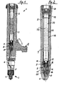
- the injection injector 1 for internal combustion engines shown in the figures has a housing 2 and is shown here schematically as a structural unit which terminates in an injection nozzle 3.
- a high pressure line 6, which emanates from a housing bore 7, in the upstream of the connection of the high-pressure line 6, as arranged in the housing bore 7 insert 8 a quantity limiting valve 9 is arranged is.
- the insert 8 designed as a quantity limiting valve 9 in turn comprises a sleeve-shaped valve housing 10, which is clamped in the housing bore 7 axially in the direction of the connection of the high-pressure line 6, and its central bore 11 forms part of the flow connection from the high-pressure-side connection 12 of the injection injector to the injection nozzle 3 forms and runs on the delimited by the valve housing 10 space part 13 of the housing bore 7, from the leading to the injection nozzle 3 high pressure line 6 goes out.
- the bore 11 of the sleeve-shaped valve housing 10 forms the guide for a cup-shaped piston 14 of the flow limiting valve 8, which is loaded on a top in the drawing, the flow direction of the counter-directed stop position over an axially against the valve housing 10 supported spring 15.
- the piston 14 is against the force of the spring 15 wegbeappel pressure-dependent adjustable, wherein the travel is limited by a re-entrant heel 16 in the bore 14. If the piston 14 is supported with its jacket on this shoulder 16, then the high-pressure-side flow connection from the connection 12 to the injection nozzle 3 is interrupted.
- the illustrated upper abutment position for the piston 14 is determined by a ring insert 17, which in turn is axially between the sleeve-shaped valve housing 10 and a support sleeve 18 which is supported opposite to the ring insert 17 against a sealing plug 19, which seals the housing bore 7 and the above a screwed against the housing 2 pressure screw 20 is braced in its support sleeve 18 supporting position.
- the housing bore 7 forms a high-pressure side storage space, the inflow starting from the connection 12 on the circumferential side to the support sleeve 18 and the fuel supplied via the connection 12 via zones of the support sleeve 18 formed as filter surfaces according to the invention on their Interior 22 transgresses, which opens on the flow control valve 9.
- the operation of the flow control valve 9 is such that only results in a displacement in the direction of the re-entrant shoulder-shaped shoulder 16 of the valve housing 10 for the piston 14 at maximum injection quantity in the regulated, clocked operation of the injection injector 1, but no Annex to paragraph 16, on the the flow path would be shut off in the direction of the injection nozzle 3. Further, in the undisturbed working operation, the timing also such that a respective injection quantity corresponding fuel volume flows over the piston 14, so that the piston 14 can be reset in turn in its illustrated upper starting position due to the given spring load.
- the quantity-limiting valve forming the insert 8 is preferably supported by the support sleeve 18 in a relatively wide range of tolerance-independent manner in that the support sleeve can be braced, in particular braced, up to the area of its squeeze limit.
- the support sleeve 18 is formed as a filter, which is indicated schematically in the figures, characterized in that the support sleeve 18 is provided with fine holes 23, which can be introduced, for example, as laser bores with little effort.
- holes 23 slots can also be provided be, which extend in the longitudinal or transverse direction in the sleeve 18.
- perforations of a different type or of another shape can also be provided, wherein the arrangement of the openings, as well as their size, can also be selected with regard to the influence of the squeezing limit.
- the holes 23, as well as openings of another type in size can be sized so that already a corresponding filter effect is achieved.
- a filter cartridge or a filter sleeve can be provided in-side to the support sleeve.
- the support sleeve 18 itself from a material having filter properties, be it entirely or partially made of an open-pored foam or of a sintered material which has corresponding filter properties.
- filter materials such as open-pore foams or sintered materials may also be provided as deposits to areas of the support sleeve forming cutouts for the support sleeve, wherein the support sleeve may also have a lattice-like structure, for example, similarly expanded metal.
Landscapes
- Engineering & Computer Science (AREA)
- Chemical & Material Sciences (AREA)
- Combustion & Propulsion (AREA)
- Mechanical Engineering (AREA)
- General Engineering & Computer Science (AREA)
- Physics & Mathematics (AREA)
- Fluid Mechanics (AREA)
- Fuel-Injection Apparatus (AREA)
Applications Claiming Priority (2)
| Application Number | Priority Date | Filing Date | Title |
|---|---|---|---|
| DE102006027614A DE102006027614B4 (de) | 2006-06-13 | 2006-06-13 | Einspritzinjektor für Brennkraftmaschinen |
| PCT/EP2007/005121 WO2007144122A1 (de) | 2006-06-13 | 2007-06-11 | Einspritzinjektor für brennkraftmaschinen |
Publications (2)
| Publication Number | Publication Date |
|---|---|
| EP2027386A1 EP2027386A1 (de) | 2009-02-25 |
| EP2027386B1 true EP2027386B1 (de) | 2010-08-25 |
Family
ID=38537578
Family Applications (1)
| Application Number | Title | Priority Date | Filing Date |
|---|---|---|---|
| EP07764607A Active EP2027386B1 (de) | 2006-06-13 | 2007-06-11 | Einspritzinjektor für brennkraftmaschinen |
Country Status (6)
| Country | Link |
|---|---|
| EP (1) | EP2027386B1 (OSRAM) |
| JP (1) | JP5189087B2 (OSRAM) |
| KR (1) | KR101390951B1 (OSRAM) |
| AT (1) | ATE479019T1 (OSRAM) |
| DE (1) | DE102006027614B4 (OSRAM) |
| WO (1) | WO2007144122A1 (OSRAM) |
Families Citing this family (7)
| Publication number | Priority date | Publication date | Assignee | Title |
|---|---|---|---|---|
| JP5176947B2 (ja) * | 2008-12-26 | 2013-04-03 | 株式会社デンソー | 高圧ポンプ |
| JP2010156256A (ja) * | 2008-12-26 | 2010-07-15 | Denso Corp | 高圧ポンプ |
| EP2354531A1 (en) * | 2010-01-19 | 2011-08-10 | Continental Automotive GmbH | Valve assembly for an injection valve and injection valve |
| CH702496B1 (de) * | 2010-05-07 | 2011-07-15 | Liebherr Machines Bulle Sa | Hochdruckinjektor. |
| AT512437B1 (de) | 2012-01-26 | 2014-03-15 | Bosch Gmbh Robert | Vorrichtung zum einspritzen von kraftstoff in den brennraum einer brennkraftmaschine |
| US20150345448A1 (en) * | 2014-05-29 | 2015-12-03 | Caterpillar Inc. | Flow limiter and filter assembly for a fuel system of an engine |
| KR101695092B1 (ko) | 2015-06-04 | 2017-01-10 | 주식회사 현대케피코 | 니들 흔들림 방지구조를 가지는 인젝터 |
Family Cites Families (23)
| Publication number | Priority date | Publication date | Assignee | Title |
|---|---|---|---|---|
| GB429405A (en) * | 1934-05-01 | 1935-05-29 | Vickers Armstrongs Ltd | Improvements in or relating to fuel sprayers for internal combustion engines |
| US2376292A (en) * | 1941-09-26 | 1945-05-15 | Reconstruction Finance Corp | Fuel injection nozzle |
| DE3122883A1 (de) * | 1981-06-10 | 1983-01-05 | Volkswagenwerk Ag, 3180 Wolfsburg | "kraftstoffeinspritzanlage fuer eine brennkraftmaschine" |
| DE69020283T2 (de) * | 1989-09-29 | 1995-10-26 | Ortech Corp | Durchflussregelsystem. |
| DE4421881A1 (de) * | 1994-06-23 | 1996-01-04 | Bosch Gmbh Robert | Ventilnadel |
| JPH08218974A (ja) * | 1995-02-17 | 1996-08-27 | Keihin Seiki Mfg Co Ltd | 電磁式燃料噴射弁 |
| DE19638201B4 (de) * | 1996-09-19 | 2005-05-04 | Robert Bosch Gmbh | Brennstoffeinspritzventil |
| DE19647304C1 (de) * | 1996-11-15 | 1998-01-22 | Daimler Benz Ag | Kraftstoffeinspritzanlage für eine Brennkraftmaschine |
| JPH1172014A (ja) * | 1997-06-24 | 1999-03-16 | Unisia Jecs Corp | 燃料加圧用ポンプ |
| DE19752834A1 (de) * | 1997-11-28 | 1999-06-02 | Bosch Gmbh Robert | Kraftstoffeinspritzeinrichtung für Brennkraftmaschinen |
| DE19860476A1 (de) * | 1998-12-28 | 2000-07-06 | Bosch Gmbh Robert | Kraftstoffeinspritzanlage |
| CZ293517B6 (cs) * | 1999-06-22 | 2004-05-12 | Škodaáautoźáa@Ás | Spojovací šroub pro opakované utahování přes mez kluzu |
| JP2001280222A (ja) * | 2000-03-30 | 2001-10-10 | Iseki & Co Ltd | ディーゼルエンジンのインジェクションポンプケーシング |
| US6446885B1 (en) * | 2001-01-16 | 2002-09-10 | Robert Bosch Corporation | Secondary filter assembly for fuel injector |
| DE10109410A1 (de) * | 2001-02-28 | 2002-09-05 | Bosch Gmbh Robert | Brennstoffeinspritzventil |
| DE10114216B4 (de) * | 2001-03-23 | 2006-11-30 | Robert Bosch Gmbh | Streckgrenzengesteuerte Schraubverbindung |
| DE10151711A1 (de) * | 2001-10-19 | 2003-04-30 | Bosch Gmbh Robert | Vorrichtung zur Abdichtung hochdruckbeaufschlagter Bauteile |
| WO2003042526A1 (en) * | 2001-11-16 | 2003-05-22 | Hitachi, Ltd. | Fuel injection valve |
| DE10212002C1 (de) * | 2002-03-18 | 2003-08-21 | Orange Gmbh | Einspritzinjektor für Brennkraftmaschinen |
| DE10334785A1 (de) * | 2003-07-30 | 2005-02-24 | Robert Bosch Gmbh | Brennstoffeinspritzventil und Verfahren zu dessen Montage |
| DE10355309A1 (de) * | 2003-11-27 | 2005-06-30 | Siemens Ag | Kraftstofffördereinheit |
| JP2005351144A (ja) * | 2004-06-09 | 2005-12-22 | Honda Motor Co Ltd | エンジンの燃料供給装置 |
| TR200402049A1 (tr) * | 2004-08-18 | 2006-03-21 | Robert Bosch Gmbh | Entegre filtreli enjektör. |
-
2006
- 2006-06-13 DE DE102006027614A patent/DE102006027614B4/de active Active
-
2007
- 2007-06-11 WO PCT/EP2007/005121 patent/WO2007144122A1/de not_active Ceased
- 2007-06-11 JP JP2009514687A patent/JP5189087B2/ja active Active
- 2007-06-11 AT AT07764607T patent/ATE479019T1/de active
- 2007-06-11 EP EP07764607A patent/EP2027386B1/de active Active
-
2008
- 2008-12-02 KR KR1020087029488A patent/KR101390951B1/ko active Active
Also Published As
| Publication number | Publication date |
|---|---|
| EP2027386A1 (de) | 2009-02-25 |
| JP2009540203A (ja) | 2009-11-19 |
| DE102006027614A1 (de) | 2007-12-27 |
| JP5189087B2 (ja) | 2013-04-24 |
| WO2007144122A1 (de) | 2007-12-21 |
| ATE479019T1 (de) | 2010-09-15 |
| DE102006027614B4 (de) | 2009-02-05 |
| KR101390951B1 (ko) | 2014-05-02 |
| KR20090018929A (ko) | 2009-02-24 |
Similar Documents
| Publication | Publication Date | Title |
|---|---|---|
| EP2027386B1 (de) | Einspritzinjektor für brennkraftmaschinen | |
| DE102014225167A1 (de) | Kraftstoffzumessventil für eine Brennkraftmaschine und Verfahren zum Betreiben desselben | |
| DE102005035347B3 (de) | Kraftstoffinjektor | |
| DE102008041730A1 (de) | Injektor mit einem vor der Zulaufdrossel angeordneten Partikelfilter | |
| DE10002273A1 (de) | Einspritzeinrichtung und Verfahren zum Einspritzen von Fluid | |
| EP1507082A1 (de) | Kraftstoffeinspritzeinrichtung für Brennkraftmaschinen | |
| DE102004017305A1 (de) | Kraftstoffeinspritzeinrichtung für Brennkraftmaschinen mit direkt ansteuerbaren Düsennadeln | |
| EP0064146A1 (de) | Einspritzsystem zum Einspritzen zweier Brennstoffe durch eine Einspritzdüse | |
| WO1998009069A1 (de) | Kraftstoffeinspritzventil für brennkraftmaschinen | |
| DE10247958A1 (de) | Kraftstoff-Einspritzvorrichtung für eine Brennkraftmaschine | |
| EP1311755A1 (de) | Kraftstoffeinspritzeinrichtung | |
| DE3145877A1 (de) | Kraftstoffeinspritzduese | |
| DE602004008630T2 (de) | Einspritzdüse | |
| DE10207189A1 (de) | Schaltbare Einspritzeinrichtung zur Einspritzung unterschiedlicher Kraftstoffmengen | |
| DE102005030220A1 (de) | Injektor mit zuschaltbarem Druckübersetzer | |
| EP0610584B1 (de) | Kraftstoffeinspritzvorrichtung für eine Vor- und Hauptspritzung unterschiedlicher Kraftstoffe über ein Einnadel-Einspritzventil | |
| DE102018200565A1 (de) | Injektor zur Dosierung von gasförmigem Kraftstoff, Gaseinblassystem mit einem solchen Injektor und Verfahren zum Betreiben dieses Injektors | |
| DE102011007106A1 (de) | Brennstoffeinspritzventil | |
| DE102008041167A1 (de) | Kraftstoffinjektor | |
| EP1397591B1 (de) | Kraftstoffeinspritzeinrichtung mit druckverstärker | |
| DE10115166C2 (de) | Druckbegrenzungsventil für Kraftstoff-Einspritzeinrichtungen | |
| DE19812011A1 (de) | Verfahren zur Einspritzung von Kraftstoff in den Brennraum einer Brennkraftmaschine und Kraftstoffeinspritzsystem | |
| EP1322866A2 (de) | Ventil zum steuern von flüssigkeiten | |
| DE102006050033A1 (de) | Injektor, insbesondere Common-Rail-Injektor | |
| EP1751423A1 (de) | Kraftstoffeinspritzsystem |
Legal Events
| Date | Code | Title | Description |
|---|---|---|---|
| PUAI | Public reference made under article 153(3) epc to a published international application that has entered the european phase |
Free format text: ORIGINAL CODE: 0009012 |
|
| 17P | Request for examination filed |
Effective date: 20081112 |
|
| AK | Designated contracting states |
Kind code of ref document: A1 Designated state(s): AT BE BG CH CY CZ DE DK EE ES FI FR GB GR HU IE IS IT LI LT LU LV MC MT NL PL PT RO SE SI SK TR |
|
| AX | Request for extension of the european patent |
Extension state: AL BA HR MK RS |
|
| GRAP | Despatch of communication of intention to grant a patent |
Free format text: ORIGINAL CODE: EPIDOSNIGR1 |
|
| DAX | Request for extension of the european patent (deleted) | ||
| RBV | Designated contracting states (corrected) |
Designated state(s): AT BE BG CH CY CZ DK EE ES FI FR GB GR HU IE IS IT LI LT LU LV MC MT NL PL PT RO SE SI SK TR |
|
| REG | Reference to a national code |
Ref country code: DE Ref legal event code: 8566 |
|
| GRAS | Grant fee paid |
Free format text: ORIGINAL CODE: EPIDOSNIGR3 |
|
| GRAA | (expected) grant |
Free format text: ORIGINAL CODE: 0009210 |
|
| AK | Designated contracting states |
Kind code of ref document: B1 Designated state(s): AT BE BG CH CY CZ DK EE ES FI FR GB GR HU IE IS IT LI LT LU LV MC MT NL PL PT RO SE SI SK TR |
|
| REG | Reference to a national code |
Ref country code: GB Ref legal event code: FG4D Free format text: NOT ENGLISH |
|
| REG | Reference to a national code |
Ref country code: CH Ref legal event code: EP |
|
| REG | Reference to a national code |
Ref country code: IE Ref legal event code: FG4D Free format text: LANGUAGE OF EP DOCUMENT: GERMAN |
|
| REG | Reference to a national code |
Ref country code: NL Ref legal event code: VDEP Effective date: 20100825 |
|
| LTIE | Lt: invalidation of european patent or patent extension |
Effective date: 20100825 |
|
| PG25 | Lapsed in a contracting state [announced via postgrant information from national office to epo] |
Ref country code: LT Free format text: LAPSE BECAUSE OF FAILURE TO SUBMIT A TRANSLATION OF THE DESCRIPTION OR TO PAY THE FEE WITHIN THE PRESCRIBED TIME-LIMIT Effective date: 20100825 |
|
| PG25 | Lapsed in a contracting state [announced via postgrant information from national office to epo] |
Ref country code: SI Free format text: LAPSE BECAUSE OF FAILURE TO SUBMIT A TRANSLATION OF THE DESCRIPTION OR TO PAY THE FEE WITHIN THE PRESCRIBED TIME-LIMIT Effective date: 20100825 Ref country code: PT Free format text: LAPSE BECAUSE OF FAILURE TO SUBMIT A TRANSLATION OF THE DESCRIPTION OR TO PAY THE FEE WITHIN THE PRESCRIBED TIME-LIMIT Effective date: 20101227 Ref country code: CY Free format text: LAPSE BECAUSE OF FAILURE TO SUBMIT A TRANSLATION OF THE DESCRIPTION OR TO PAY THE FEE WITHIN THE PRESCRIBED TIME-LIMIT Effective date: 20100825 Ref country code: BG Free format text: LAPSE BECAUSE OF FAILURE TO SUBMIT A TRANSLATION OF THE DESCRIPTION OR TO PAY THE FEE WITHIN THE PRESCRIBED TIME-LIMIT Effective date: 20101125 Ref country code: PL Free format text: LAPSE BECAUSE OF FAILURE TO SUBMIT A TRANSLATION OF THE DESCRIPTION OR TO PAY THE FEE WITHIN THE PRESCRIBED TIME-LIMIT Effective date: 20100825 Ref country code: IS Free format text: LAPSE BECAUSE OF FAILURE TO SUBMIT A TRANSLATION OF THE DESCRIPTION OR TO PAY THE FEE WITHIN THE PRESCRIBED TIME-LIMIT Effective date: 20101225 |
|
| REG | Reference to a national code |
Ref country code: IE Ref legal event code: FD4D |
|
| PG25 | Lapsed in a contracting state [announced via postgrant information from national office to epo] |
Ref country code: NL Free format text: LAPSE BECAUSE OF FAILURE TO SUBMIT A TRANSLATION OF THE DESCRIPTION OR TO PAY THE FEE WITHIN THE PRESCRIBED TIME-LIMIT Effective date: 20100825 Ref country code: SE Free format text: LAPSE BECAUSE OF FAILURE TO SUBMIT A TRANSLATION OF THE DESCRIPTION OR TO PAY THE FEE WITHIN THE PRESCRIBED TIME-LIMIT Effective date: 20100825 Ref country code: LV Free format text: LAPSE BECAUSE OF FAILURE TO SUBMIT A TRANSLATION OF THE DESCRIPTION OR TO PAY THE FEE WITHIN THE PRESCRIBED TIME-LIMIT Effective date: 20100825 Ref country code: GR Free format text: LAPSE BECAUSE OF FAILURE TO SUBMIT A TRANSLATION OF THE DESCRIPTION OR TO PAY THE FEE WITHIN THE PRESCRIBED TIME-LIMIT Effective date: 20101126 |
|
| PG25 | Lapsed in a contracting state [announced via postgrant information from national office to epo] |
Ref country code: DK Free format text: LAPSE BECAUSE OF FAILURE TO SUBMIT A TRANSLATION OF THE DESCRIPTION OR TO PAY THE FEE WITHIN THE PRESCRIBED TIME-LIMIT Effective date: 20100825 Ref country code: IE Free format text: LAPSE BECAUSE OF FAILURE TO SUBMIT A TRANSLATION OF THE DESCRIPTION OR TO PAY THE FEE WITHIN THE PRESCRIBED TIME-LIMIT Effective date: 20100825 |
|
| PG25 | Lapsed in a contracting state [announced via postgrant information from national office to epo] |
Ref country code: EE Free format text: LAPSE BECAUSE OF FAILURE TO SUBMIT A TRANSLATION OF THE DESCRIPTION OR TO PAY THE FEE WITHIN THE PRESCRIBED TIME-LIMIT Effective date: 20100825 Ref country code: RO Free format text: LAPSE BECAUSE OF FAILURE TO SUBMIT A TRANSLATION OF THE DESCRIPTION OR TO PAY THE FEE WITHIN THE PRESCRIBED TIME-LIMIT Effective date: 20100825 Ref country code: SK Free format text: LAPSE BECAUSE OF FAILURE TO SUBMIT A TRANSLATION OF THE DESCRIPTION OR TO PAY THE FEE WITHIN THE PRESCRIBED TIME-LIMIT Effective date: 20100825 Ref country code: CZ Free format text: LAPSE BECAUSE OF FAILURE TO SUBMIT A TRANSLATION OF THE DESCRIPTION OR TO PAY THE FEE WITHIN THE PRESCRIBED TIME-LIMIT Effective date: 20100825 |
|
| PG25 | Lapsed in a contracting state [announced via postgrant information from national office to epo] |
Ref country code: ES Free format text: LAPSE BECAUSE OF FAILURE TO SUBMIT A TRANSLATION OF THE DESCRIPTION OR TO PAY THE FEE WITHIN THE PRESCRIBED TIME-LIMIT Effective date: 20101206 |
|
| PLBE | No opposition filed within time limit |
Free format text: ORIGINAL CODE: 0009261 |
|
| STAA | Information on the status of an ep patent application or granted ep patent |
Free format text: STATUS: NO OPPOSITION FILED WITHIN TIME LIMIT |
|
| 26N | No opposition filed |
Effective date: 20110526 |
|
| PG25 | Lapsed in a contracting state [announced via postgrant information from national office to epo] |
Ref country code: MT Free format text: LAPSE BECAUSE OF FAILURE TO SUBMIT A TRANSLATION OF THE DESCRIPTION OR TO PAY THE FEE WITHIN THE PRESCRIBED TIME-LIMIT Effective date: 20100825 |
|
| BERE | Be: lapsed |
Owner name: L'ORANGE G.M.B.H. Effective date: 20110630 |
|
| REG | Reference to a national code |
Ref country code: FR Ref legal event code: ST Effective date: 20120229 |
|
| PG25 | Lapsed in a contracting state [announced via postgrant information from national office to epo] |
Ref country code: BE Free format text: LAPSE BECAUSE OF NON-PAYMENT OF DUE FEES Effective date: 20110630 |
|
| PG25 | Lapsed in a contracting state [announced via postgrant information from national office to epo] |
Ref country code: FR Free format text: LAPSE BECAUSE OF NON-PAYMENT OF DUE FEES Effective date: 20110630 |
|
| PG25 | Lapsed in a contracting state [announced via postgrant information from national office to epo] |
Ref country code: MC Free format text: LAPSE BECAUSE OF NON-PAYMENT OF DUE FEES Effective date: 20110630 |
|
| PG25 | Lapsed in a contracting state [announced via postgrant information from national office to epo] |
Ref country code: LU Free format text: LAPSE BECAUSE OF NON-PAYMENT OF DUE FEES Effective date: 20110611 |
|
| PG25 | Lapsed in a contracting state [announced via postgrant information from national office to epo] |
Ref country code: TR Free format text: LAPSE BECAUSE OF FAILURE TO SUBMIT A TRANSLATION OF THE DESCRIPTION OR TO PAY THE FEE WITHIN THE PRESCRIBED TIME-LIMIT Effective date: 20100825 |
|
| PG25 | Lapsed in a contracting state [announced via postgrant information from national office to epo] |
Ref country code: HU Free format text: LAPSE BECAUSE OF FAILURE TO SUBMIT A TRANSLATION OF THE DESCRIPTION OR TO PAY THE FEE WITHIN THE PRESCRIBED TIME-LIMIT Effective date: 20100825 |
|
| PGFP | Annual fee paid to national office [announced via postgrant information from national office to epo] |
Ref country code: FI Payment date: 20250625 Year of fee payment: 19 |
|
| PGFP | Annual fee paid to national office [announced via postgrant information from national office to epo] |
Ref country code: GB Payment date: 20250627 Year of fee payment: 19 |
|
| PGFP | Annual fee paid to national office [announced via postgrant information from national office to epo] |
Ref country code: AT Payment date: 20250521 Year of fee payment: 19 |
|
| PGFP | Annual fee paid to national office [announced via postgrant information from national office to epo] |
Ref country code: IT Payment date: 20250619 Year of fee payment: 19 |
|
| PGFP | Annual fee paid to national office [announced via postgrant information from national office to epo] |
Ref country code: CH Payment date: 20250701 Year of fee payment: 19 |