EP2021641B1 - Cage pour roulement a billes - Google Patents
Cage pour roulement a billes Download PDFInfo
- Publication number
- EP2021641B1 EP2021641B1 EP07788939A EP07788939A EP2021641B1 EP 2021641 B1 EP2021641 B1 EP 2021641B1 EP 07788939 A EP07788939 A EP 07788939A EP 07788939 A EP07788939 A EP 07788939A EP 2021641 B1 EP2021641 B1 EP 2021641B1
- Authority
- EP
- European Patent Office
- Prior art keywords
- cage
- heel
- axial portion
- substantially axial
- diameter
- Prior art date
- Legal status (The legal status is an assumption and is not a legal conclusion. Google has not performed a legal analysis and makes no representation as to the accuracy of the status listed.)
- Active
Links
Images


Classifications
-
- F—MECHANICAL ENGINEERING; LIGHTING; HEATING; WEAPONS; BLASTING
- F16—ENGINEERING ELEMENTS AND UNITS; GENERAL MEASURES FOR PRODUCING AND MAINTAINING EFFECTIVE FUNCTIONING OF MACHINES OR INSTALLATIONS; THERMAL INSULATION IN GENERAL
- F16C—SHAFTS; FLEXIBLE SHAFTS; ELEMENTS OR CRANKSHAFT MECHANISMS; ROTARY BODIES OTHER THAN GEARING ELEMENTS; BEARINGS
- F16C33/00—Parts of bearings; Special methods for making bearings or parts thereof
- F16C33/30—Parts of ball or roller bearings
- F16C33/66—Special parts or details in view of lubrication
- F16C33/6603—Special parts or details in view of lubrication with grease as lubricant
- F16C33/6607—Retaining the grease in or near the bearing
- F16C33/6614—Retaining the grease in or near the bearing in recesses or cavities provided in retainers, races or rolling elements
-
- F—MECHANICAL ENGINEERING; LIGHTING; HEATING; WEAPONS; BLASTING
- F16—ENGINEERING ELEMENTS AND UNITS; GENERAL MEASURES FOR PRODUCING AND MAINTAINING EFFECTIVE FUNCTIONING OF MACHINES OR INSTALLATIONS; THERMAL INSULATION IN GENERAL
- F16C—SHAFTS; FLEXIBLE SHAFTS; ELEMENTS OR CRANKSHAFT MECHANISMS; ROTARY BODIES OTHER THAN GEARING ELEMENTS; BEARINGS
- F16C33/00—Parts of bearings; Special methods for making bearings or parts thereof
- F16C33/30—Parts of ball or roller bearings
- F16C33/38—Ball cages
- F16C33/41—Ball cages comb-shaped
- F16C33/418—Details of individual pockets, e.g. shape or ball retaining means
-
- F—MECHANICAL ENGINEERING; LIGHTING; HEATING; WEAPONS; BLASTING
- F16—ENGINEERING ELEMENTS AND UNITS; GENERAL MEASURES FOR PRODUCING AND MAINTAINING EFFECTIVE FUNCTIONING OF MACHINES OR INSTALLATIONS; THERMAL INSULATION IN GENERAL
- F16C—SHAFTS; FLEXIBLE SHAFTS; ELEMENTS OR CRANKSHAFT MECHANISMS; ROTARY BODIES OTHER THAN GEARING ELEMENTS; BEARINGS
- F16C19/00—Bearings with rolling contact, for exclusively rotary movement
- F16C19/02—Bearings with rolling contact, for exclusively rotary movement with bearing balls essentially of the same size in one or more circular rows
- F16C19/04—Bearings with rolling contact, for exclusively rotary movement with bearing balls essentially of the same size in one or more circular rows for radial load mainly
- F16C19/06—Bearings with rolling contact, for exclusively rotary movement with bearing balls essentially of the same size in one or more circular rows for radial load mainly with a single row or balls
Definitions
- the present invention relates to the field of rolling cages, in particular the cages of synthetic material used in deep groove ball bearings in order to ensure the proper circumferential spacing between the balls.
- the invention also relates to cages for rings bearing thin sheet metal.
- Such types of cages have a generally annular shape with spherical cells in which the balls are partially housed.
- the balls are held in the cells by claws arranged in pairs opposite the heel of the cage.
- the spherical cells have a diameter slightly greater than that of the balls, so that a certain functional clearance between beads and cells exists.
- the present invention aims to overcome these disadvantages.
- the present invention aims to reduce the radial deformations of the end of the cage opposite the heel while relieving said cage.
- the ball bearing cage comprises an annular bead and a substantially axial portion provided with claws defining cells for balls and connected to the bead.
- the substantially axial portion extends axially over a length greater than or equal to half the diameter of the cells.
- the substantially axial portion has an outer diameter less than the outer diameter of the heel. The outer diameter of the substantially axial portion is between the pitch diameter of the cage decreased by half the radial thickness of the bead and the pitch diameter of the cage increased by half the radial thickness of the bead as described in FIG. document JP-A-2003-329045 (NSK Ltd.)
- pitch diameter of the cage means the diameter of the imaginary circle passing through the center of the fictitious spheres defining the cells.
- the pitch diameter of the cage is substantially equal to the pitch diameter of the bearing, that is to say the diameter of the fictitious circle joining the centers of the balls.
- This provides a lightening of the substantially axial portion of the cage whose radial thickness is reduced relative to that of the heel, resulting in a reduction in the cost of the raw material of the cage, mass and inertia of the cage.
- the substantially axial portion having a significant length, the lightening is important. With this lightening, the cage is deformed less at high speed, resulting in a reduction in the wear of the cage and the balls.
- the substantially axial portion has at least a portion of its length a draft angle less than 6 °, for example of the order of 4 °. This facilitates demolding of the substantially axial portion made of molded synthetic material.
- the substantially axial portion extends axially over a length at least equal to 60% of the diameter of the cells.
- the substantially axial portion may have an outer diameter less than or equal to 95% of the outer diameter of the heel.
- the outer diameter of the substantially axial portion is between the pitch diameter of the cage decreased by one third of the radial thickness of the heel and the pitch diameter of the cage increased by one third of the radial thickness of the heel.
- the cage comprises a connection between the heel and the radial portion.
- the connection extends axially over a length less than that of the axial portion. This gives a high radial rigidity of the axial portion.
- the connection may extend over a length less than one third of the length of the axial portion.
- the substantially axial portion and the connection may extend axially over at least half the diameter of the cells.
- openings are formed in the heel, the openings opening on at least two faces of the heel.
- the openings may be arranged angularly at equidistance between two cells. This provides a significant relief of the heel.
- hollow areas are formed from the outer face of the axial portion.
- the hollow zones can be arranged angularly at equidistance between two cells. We are lightening thus the axial portion, resulting in a gain in material and a decrease in the deformation due to the speed,
- the openings and the hollow areas being in communication.
- the substantially axial portion comprises a plurality of inter-alveolar protuberances.
- a protuberance comprises two branches defining the cells and connecting to the heel, a rib connecting the branches away from the heel and away from the free ends of the branches, and a partition disposed between the branches, the rib and the heel.
- the partition may have a radial thickness less than the radial thickness of the branches.
- the cage comprises polyamide filled with glass fibers.
- the cage comprises polyether-ether-ketone.
- the invention also relates to a rolling bearing comprising rolling elements arranged between two rolling tracks and mounted in the cells of a cage.
- the cage comprises an annular heel and a substantially axial portion provided with claws defining said cells and being connected to the heel.
- the substantially axial portion extends axially over a portion of the length of the rolling elements.
- the substantially axial portion has an outer diameter less than the outer diameter of the heel. The outer diameter of the substantially axial portion is between the pitch diameter of the cage decreased by half the radial thickness of the bead and the pitch diameter of the cage increased by half the radial thickness of the bead.
- the weight gain of a cage can be of the order of 20 to 30%, for example 25%, while the radial deformation can be reduced by about 30 to 40%, for example 35%.
- a bearing can be used at a speed of rotation that is 17% greater than a bearing equipped with a conventional cage, for example 700 000 ndm instead of 600 000 ndm, the ndm being a speed factor resulting from the produces rotational speed in rpm by the pitch diameter of the bearing in mm.
- the ndm is representative of the linear speed of movement of the balls.
- the cage also allows, for a given speed, use with higher operating temperatures than in the case of a conventional cage, and this thanks to the reduction of the deformation and the increase of the space available for the lubricant.
- the operating temperature limit can be extended from 120 ° C to 150 ° C.
- reducing the amount of material forming the cage has a significant effect of reducing the cost of raw material.
- the rolling bearing comprises an outer ring 1, an inner ring 2, a row of rolling elements 3, here balls, a cage 4 for maintaining the circumferential spacing of the rolling elements 3 and sealing flanges 5 and 6.
- the outer ring 1 and inner 2 are deep groove type, for example obtained by machining a portion of tube.
- the outer ring 1 comprises a cylindrical axial outer surface 1a, opposite radial end surfaces 1b and 1c, and a bore from which is formed a raceway 1d for the rolling elements 3.
- the inner ring 2 comprises a cylindrical bore 2a, two opposite radial frontal surfaces 2b and 2c and a surface outside of which is formed a rolling track 2d for the rolling elements 3.
- the outer ring 1 is provided with two symmetrical grooves, in which the sealing flanges 5 and 6 are respectively fitted on the side of the radial surface 1b and of the radial surface 1c.
- the sealing flanges 5 and 6 form a narrow passage with a cylindrical bearing surface of the inner ring 2 located between the rolling track 2d and the respective front radial surfaces 2b and 2c.
- the cage 4 is better visible on the figure 2 and comprises an annular heel 7 and an axial portion 8 defining a plurality of cells for the rolling elements 3.
- the cells 9 are of spherical or quasi-spherical shape.
- the heel 7 has an outer diameter greater than that of the axial portion 8 and an inner diameter equal.
- a bead having an inside diameter slightly different from that of the axial portion 8 could be provided.
- the axial portion 8 has an axial length at least equal to half the diameter of the cells 9, so that the rolling elements 3 can be properly retained in said cells 9.
- the outer diameter of the substantially axial portion 8 is in the range defined between the pitch diameter of the cage minus half the radial thickness of the bead and the pitch diameter of the the cage plus half the radial thickness of the heel.
- the pitch diameter of the cage is the diameter of the fictitious circle passing through the center of the fictitious spheres defining the cells 9.
- the axial portion 8 forms a protuberance comprising two branches 10 in an arc, each ending in a claw 11 axially opposite the heel 7.
- the axial portion 8 also comprises a rib 12 connecting the ends the two branches 10 opposite the heel 7. Beyond the rib 12, extend the claws 11.
- the branches 10, the claws 11 and the rib 12 may have an equal radial thickness.
- the cage 1 also comprises a connection 13 located at the base of each branch 10 and forming an interface between the heel 7 and the branch 10.
- the connection 13 has a rounded profile in cross-section and has a decreasing radial thickness from the heel 7 to the branch 10.
- the branches 10 form ribs having a sufficient surface to form the cells 9 for retaining the rolling elements 3 .
- the axial portion 8 also comprises a partition 14 connecting two branches 10 of two neighboring cells 9.
- the partition 14 has a small radial thickness, for example less than half the radial thickness of the branches 10, and extends axially between the heel 7 and the rib 12.
- the partition 14 is disposed on the inner face of the part axial axis 8 and leaves on the outer face a hollow zone 16.
- the hollow zones 16 extend axially between the heel 7 and the rib 12, circumferentially between two branches 10 of two neighboring cells 9 and radially between the partition 14 and the outer face of the axial portion 8.
- the partition 14 is delimited radially inwards by the cylindrical inner surface of the cage 1.
- Openings 15 are also formed in the heel 7 and extend axially between the face of the heel 7 opposite to the axial portion 8 and the hollow zones 16.
- the openings 15 and the hollow zones 16 are thus in mutual communication, which facilitates the manufacture of the cage, for example by molding.
- the presence of the openings 15 and the hollow areas 16 promotes the circulation of lubricant inside the bearing.
- the openings 15 are defined circumferentially substantially at the openings 16 and therefore between the root of each leg 10 and radially, so as to leave a heel portion 7 on the inside and another heel portion 7 on the outside. .
- the amount of material required for the formation of the cage 4 is significantly reduced, resulting in a reduction in material cost.
- first and a reduction of the mass which makes it possible to reduce the radial deformation during rotation at high speed.
- the shape of the axial part 8 with branches forming stiffening ribs and the partition 14 which also increases the rigidity on the side of the axial portion 8 under axial tensile stresses during a radial bending deformation of the entire axial portion 8, also reduces said radial bending deformation, the heel 7 remaining relatively radially deformable due to its annular structure.
- the outer diameter of the axial portion 8 is slightly greater than the original diameter of the cage and remains less than the sum of the pitch diameter of the cage and half the radial thickness of the heel 7.
- the outer diameter of the axial portion 8 is substantially equal to the pitch diameter of the cage 4.
- the outer diameter of the axial portion 8 is less than the pitch diameter while remaining greater than the pitch diameter decreased by half the radial thickness of the heel 7.
- This embodiment provides a particularly lightweight cage and therefore economical. Its deformation may be slightly greater, without particular damage, because of the significant distance existing radially between the claws 11 and the bore of the outer ring of the bearing. This distance may be greater than the radius of the cells.
- the axial portion 8 and the heel 7 are directly connected, the heel 7 having a radial surface 7a on the side of the axial portion 8.
- the rounding connection 13 of the previous embodiment is not present.
- connection 13 is in the form of a chamfer substantially at 45 ° and having a relatively small axial length, of the order of 15 to 25% of the length of the axial portion 8.
- the presence of a connection allows to increase the radial rigidity of the axial portion 8, with a very small increase in mass.
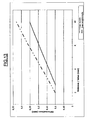
- the curve of the figure 13 shows, for a given operating point of a given bearing, in other words at a particular speed of rotation of a cage of particular pitch diameter, the evolution of the radial deformation of the axial portion 8 of the cage 4 as a function of the distance relative to the heel 7 of the point whose deformation is measured, and this for a conventional cage and for the cage according to the invention.
- the cage according to the invention has a deformation of 0.15 mm
- the conventional cage already has a deformation of 0.2 mm, and at an equal distance from the heel.
- the invention offers a significant reduction in the radial deformation and consequently an improvement in the regularity of the lubricant film.
- the increase in speed may be substantially equal to the square root of the reduction of the deformation by passing from a conventional cage to a cage according to the invention.
Applications Claiming Priority (2)
| Application Number | Priority Date | Filing Date | Title |
|---|---|---|---|
| FR0604232A FR2900996B1 (fr) | 2006-05-12 | 2006-05-12 | Cage pour roulement a billes |
| PCT/FR2007/051101 WO2007135305A1 (fr) | 2006-05-12 | 2007-04-12 | Cage pour roulement a billes |
Publications (2)
| Publication Number | Publication Date |
|---|---|
| EP2021641A1 EP2021641A1 (fr) | 2009-02-11 |
| EP2021641B1 true EP2021641B1 (fr) | 2010-06-09 |
Family
ID=37607045
Family Applications (1)
| Application Number | Title | Priority Date | Filing Date |
|---|---|---|---|
| EP07788939A Active EP2021641B1 (fr) | 2006-05-12 | 2007-04-12 | Cage pour roulement a billes |
Country Status (11)
| Country | Link |
|---|---|
| US (1) | US8157449B2 (ja) |
| EP (1) | EP2021641B1 (ja) |
| JP (1) | JP5436204B2 (ja) |
| KR (1) | KR20090007742A (ja) |
| CN (1) | CN101443568B (ja) |
| AT (1) | ATE470799T1 (ja) |
| AU (1) | AU2007253124B2 (ja) |
| BR (1) | BRPI0711322B1 (ja) |
| DE (1) | DE602007007076D1 (ja) |
| FR (1) | FR2900996B1 (ja) |
| WO (1) | WO2007135305A1 (ja) |
Families Citing this family (21)
| Publication number | Priority date | Publication date | Assignee | Title |
|---|---|---|---|---|
| WO2007133746A2 (en) * | 2006-05-15 | 2007-11-22 | Biogen Idec Ma Inc. | Use of nogo receptor-1 (ngr1) antagonists for promoting oligodendrocyte survival |
| FR2911934B1 (fr) * | 2007-01-26 | 2009-09-18 | Skf Ab | Cage pour roulement a billes |
| FR2921451B1 (fr) * | 2007-09-26 | 2010-02-26 | Skf Ab | Palier a roulement et cage pour un tel palier |
| WO2010067852A1 (ja) | 2008-12-10 | 2010-06-17 | 日本精工株式会社 | 玉軸受及びハイブリッド車用変速機 |
| JP5764959B2 (ja) * | 2011-02-10 | 2015-08-19 | 日本精工株式会社 | 玉軸受 |
| US20120308172A1 (en) * | 2011-06-01 | 2012-12-06 | Schaeffler Technologies Gmbh & Co. Kg | Double row, tandem, angular contact, ball bearing assembly |
| JP2013200006A (ja) * | 2012-03-26 | 2013-10-03 | Ntn Corp | 玉軸受およびその保持器 |
| FR2994720B1 (fr) | 2012-08-22 | 2015-07-03 | Skf Ab | Cage pour palier a roulement, palier a roulement et direction electrique de vehicule automobile |
| FR2996889B1 (fr) * | 2012-10-12 | 2015-04-24 | Skf Ab | Cage pour roulement, notamment pour roulement de direction electrique de vehicule automobile |
| JP6211260B2 (ja) * | 2012-11-16 | 2017-10-11 | Ntn株式会社 | 冠形保持器および玉軸受 |
| DE102012222800A1 (de) * | 2012-12-11 | 2014-06-12 | Schaeffler Technologies Gmbh & Co. Kg | Zweiteiliger Lagerkäfig mit Halteschalen und Kugellager, umfassend einen solchen zweiteiligen Lagerkäfig |
| WO2016013571A1 (ja) | 2014-07-23 | 2016-01-28 | 株式会社不二越 | 転がり軸受 |
| CN104141682B (zh) * | 2014-07-25 | 2016-08-31 | 慈溪新美培林精密轴承有限公司 | 一种法兰轴承 |
| US9546682B2 (en) * | 2014-12-09 | 2017-01-17 | Aktiebolaget Skf | Cage of a rolling bearing, rolling bearing comprising such a cage and apparatus comprising such a rolling bearing |
| FR3072142B1 (fr) * | 2017-10-06 | 2019-09-27 | Psa Automobiles Sa | Dispositif de prehension et de maintien a l’etat pre-assemble d’un synchroniseur de boite de vitesses d’un vehicule automobile |
| JP2021139410A (ja) | 2020-03-03 | 2021-09-16 | 日本精工株式会社 | 玉軸受用冠型保持器、及び玉軸受 |
| US11286988B2 (en) * | 2020-07-27 | 2022-03-29 | Schaeffler Technologies AG & Co. KG | Single-piece high-speed bearing cage |
| JP7420274B2 (ja) | 2021-01-18 | 2024-01-23 | 日本精工株式会社 | 玉軸受用冠型保持器、及び玉軸受 |
| WO2022154125A1 (ja) * | 2021-01-18 | 2022-07-21 | 日本精工株式会社 | 玉軸受用冠型保持器、及び玉軸受 |
| WO2023199646A1 (ja) * | 2022-04-15 | 2023-10-19 | 日本精工株式会社 | 玉軸受用冠型保持器、及び玉軸受 |
| CN117145871B (zh) * | 2023-10-31 | 2024-01-26 | 万向钱潮股份公司 | 一种高强度轻量化高速深沟球轴承用保持架 |
Family Cites Families (19)
| Publication number | Priority date | Publication date | Assignee | Title |
|---|---|---|---|---|
| JPS5556917U (ja) * | 1978-10-13 | 1980-04-17 | ||
| JPS61215811A (ja) * | 1986-03-28 | 1986-09-25 | Koyo Seiko Co Ltd | 玉軸受用合成樹脂装冠形保持器 |
| AT387826B (de) * | 1986-07-24 | 1989-03-28 | Camillo Krejci | Kugellagerkaefig |
| JPH0648180Y2 (ja) * | 1989-04-07 | 1994-12-12 | 光洋精工株式会社 | 冠形保持器 |
| JPH03130427U (ja) * | 1990-04-11 | 1991-12-27 | ||
| DE4141759C2 (de) * | 1991-12-18 | 1993-10-07 | Krupp Industrietech | Kugelbahndrehverbindung |
| JPH0645116U (ja) * | 1992-11-30 | 1994-06-14 | エヌティエヌ株式会社 | 転がり軸受 |
| JPH11210757A (ja) * | 1998-01-23 | 1999-08-03 | Koyo Seiko Co Ltd | 合成樹脂製冠形保持器 |
| JP2000291662A (ja) * | 1999-04-07 | 2000-10-20 | Ntn Corp | 玉軸受 |
| JP2001027248A (ja) * | 1999-07-14 | 2001-01-30 | Minebea Co Ltd | 転がり軸受用保持器 |
| FR2796680B1 (fr) * | 1999-07-23 | 2001-09-14 | Skf France | Dispositif de cage pour roulement a billes et roulement associe |
| JP2002098151A (ja) * | 2000-09-22 | 2002-04-05 | Nsk Ltd | 転がり軸受用保持器および転がり軸受 |
| JP2002139049A (ja) * | 2000-10-31 | 2002-05-17 | Nsk Ltd | 転がり軸受 |
| JP2002147463A (ja) | 2000-11-13 | 2002-05-22 | Nsk Ltd | 冠型保持器 |
| FR2821651B1 (fr) * | 2001-03-01 | 2004-05-14 | Roulements Soc Nouvelle | Cage a reserve de substance lubrifiante |
| JP2003035317A (ja) * | 2001-07-24 | 2003-02-07 | Nsk Ltd | 冠型合成樹脂製保持器および転がり軸受 |
| JP2003287032A (ja) * | 2002-03-28 | 2003-10-10 | Nsk Ltd | 玉軸受用プラスチック製冠型保持器 |
| JP2003329045A (ja) * | 2002-05-13 | 2003-11-19 | Nsk Ltd | ハイブリッド車駆動モータ用転がり軸受及びハイブリッド車駆動モータ |
| CN2630558Y (zh) * | 2003-07-24 | 2004-08-04 | 合普工业股份有限公司 | 轴承 |
-
2006
- 2006-05-12 FR FR0604232A patent/FR2900996B1/fr active Active
-
2007
- 2007-04-12 WO PCT/FR2007/051101 patent/WO2007135305A1/fr active Application Filing
- 2007-04-12 AU AU2007253124A patent/AU2007253124B2/en active Active
- 2007-04-12 KR KR1020087026978A patent/KR20090007742A/ko not_active Application Discontinuation
- 2007-04-12 CN CN2007800172858A patent/CN101443568B/zh active Active
- 2007-04-12 JP JP2009508429A patent/JP5436204B2/ja active Active
- 2007-04-12 DE DE602007007076T patent/DE602007007076D1/de active Active
- 2007-04-12 EP EP07788939A patent/EP2021641B1/fr active Active
- 2007-04-12 AT AT07788939T patent/ATE470799T1/de not_active IP Right Cessation
- 2007-04-12 US US12/227,187 patent/US8157449B2/en active Active
- 2007-04-12 BR BRPI0711322-6A patent/BRPI0711322B1/pt active IP Right Grant
Also Published As
| Publication number | Publication date |
|---|---|
| BRPI0711322A2 (pt) | 2011-08-23 |
| AU2007253124B2 (en) | 2012-02-02 |
| JP5436204B2 (ja) | 2014-03-05 |
| WO2007135305A1 (fr) | 2007-11-29 |
| US8157449B2 (en) | 2012-04-17 |
| BRPI0711322B1 (pt) | 2019-05-14 |
| AU2007253124A1 (en) | 2007-11-29 |
| JP2009536998A (ja) | 2009-10-22 |
| FR2900996A1 (fr) | 2007-11-16 |
| CN101443568B (zh) | 2011-04-06 |
| KR20090007742A (ko) | 2009-01-20 |
| ATE470799T1 (de) | 2010-06-15 |
| CN101443568A (zh) | 2009-05-27 |
| DE602007007076D1 (de) | 2010-07-22 |
| FR2900996B1 (fr) | 2008-08-08 |
| EP2021641A1 (fr) | 2009-02-11 |
| US20100046875A1 (en) | 2010-02-25 |
Similar Documents
| Publication | Publication Date | Title |
|---|---|---|
| EP2021641B1 (fr) | Cage pour roulement a billes | |
| FR2911934A1 (fr) | Cage pour roulement a billes | |
| EP1956254B1 (fr) | Dispositif de roulement et colonne de direction | |
| US10907687B2 (en) | Lubrication groove for deep groove ball bearing | |
| FR2945090A1 (fr) | Palier a roulement comportant une enveloppe de maintien d'une des bagues | |
| EP1070866A1 (fr) | Dispositif de cage pour roulement à billes et roulement associé | |
| FR2936767A1 (fr) | Palier a roulement, notamment pour colonne de direction. | |
| FR2921451A1 (fr) | Palier a roulement et cage pour un tel palier | |
| EP1908980B1 (fr) | Dispositif de poulie débrayable | |
| FR2869081A1 (fr) | Palier a roulement | |
| EP1900958B1 (fr) | Dispositif de poulie débrayable. | |
| FR3068745A1 (fr) | Dispositif de mesure d’huile et de retenue de graisse pour une unite de palier a roulement | |
| FR2953576A1 (fr) | Joint d'etancheite et palier a roulement comportant un tel joint. | |
| FR2792043A1 (fr) | Procede de fabrication de cage pour roulement | |
| EP2963307B1 (fr) | Cage de rétention de corps roulants dans un palier à roulement | |
| EP2811189A1 (fr) | Cage segmentée pour unité de roulement. | |
| FR2775323A1 (fr) | Cage pour roulement rigide a billes et roulement associe | |
| FR2886693A1 (fr) | Dispositif anti-rotation pour bague de roulement, et roulement et machine associes | |
| FR2802990A1 (fr) | Roulement, roue equipee d'un tel roulement, procede de fabrication d'une roue equipee d'un roulement, et roue obtenue par ce procede | |
| EP2878841B1 (fr) | Cage de rétention de corps roulants dans un palier à roulement | |
| EP3081823B1 (fr) | Unite de roulement et procede pour fabriquer une telle unite de roulement | |
| EP1806524A1 (fr) | Garniture d'étanchéité tournante et palier à roulement comportant une telle garniture | |
| FR3034151A1 (fr) | Palier comprenant une bague d'usure surmoulee, et procede de fabrication associe | |
| FR3120671A1 (fr) | Segment de garniture de friction | |
| FR3112826A1 (fr) | Cage de roulement à gorges de drainage |
Legal Events
| Date | Code | Title | Description |
|---|---|---|---|
| PUAI | Public reference made under article 153(3) epc to a published international application that has entered the european phase |
Free format text: ORIGINAL CODE: 0009012 |
|
| 17P | Request for examination filed |
Effective date: 20081007 |
|
| AK | Designated contracting states |
Kind code of ref document: A1 Designated state(s): AT BE BG CH CY CZ DE DK EE ES FI FR GB GR HU IE IS IT LI LT LU LV MC MT NL PL PT RO SE SI SK TR |
|
| AX | Request for extension of the european patent |
Extension state: AL BA HR MK RS |
|
| 17Q | First examination report despatched |
Effective date: 20090210 |
|
| GRAP | Despatch of communication of intention to grant a patent |
Free format text: ORIGINAL CODE: EPIDOSNIGR1 |
|
| GRAS | Grant fee paid |
Free format text: ORIGINAL CODE: EPIDOSNIGR3 |
|
| DAX | Request for extension of the european patent (deleted) | ||
| GRAA | (expected) grant |
Free format text: ORIGINAL CODE: 0009210 |
|
| AK | Designated contracting states |
Kind code of ref document: B1 Designated state(s): AT BE BG CH CY CZ DE DK EE ES FI FR GB GR HU IE IS IT LI LT LU LV MC MT NL PL PT RO SE SI SK TR |
|
| REG | Reference to a national code |
Ref country code: CH Ref legal event code: EP |
|
| REG | Reference to a national code |
Ref country code: IE Ref legal event code: FG4D Free format text: LANGUAGE OF EP DOCUMENT: FRENCH |
|
| REF | Corresponds to: |
Ref document number: 602007007076 Country of ref document: DE Date of ref document: 20100722 Kind code of ref document: P |
|
| REG | Reference to a national code |
Ref country code: NL Ref legal event code: VDEP Effective date: 20100609 |
|
| PG25 | Lapsed in a contracting state [announced via postgrant information from national office to epo] |
Ref country code: LT Free format text: LAPSE BECAUSE OF FAILURE TO SUBMIT A TRANSLATION OF THE DESCRIPTION OR TO PAY THE FEE WITHIN THE PRESCRIBED TIME-LIMIT Effective date: 20100609 Ref country code: SE Free format text: LAPSE BECAUSE OF FAILURE TO SUBMIT A TRANSLATION OF THE DESCRIPTION OR TO PAY THE FEE WITHIN THE PRESCRIBED TIME-LIMIT Effective date: 20100609 |
|
| LTIE | Lt: invalidation of european patent or patent extension |
Effective date: 20100609 |
|
| PG25 | Lapsed in a contracting state [announced via postgrant information from national office to epo] |
Ref country code: LV Free format text: LAPSE BECAUSE OF FAILURE TO SUBMIT A TRANSLATION OF THE DESCRIPTION OR TO PAY THE FEE WITHIN THE PRESCRIBED TIME-LIMIT Effective date: 20100609 Ref country code: SI Free format text: LAPSE BECAUSE OF FAILURE TO SUBMIT A TRANSLATION OF THE DESCRIPTION OR TO PAY THE FEE WITHIN THE PRESCRIBED TIME-LIMIT Effective date: 20100609 Ref country code: AT Free format text: LAPSE BECAUSE OF FAILURE TO SUBMIT A TRANSLATION OF THE DESCRIPTION OR TO PAY THE FEE WITHIN THE PRESCRIBED TIME-LIMIT Effective date: 20100609 Ref country code: FI Free format text: LAPSE BECAUSE OF FAILURE TO SUBMIT A TRANSLATION OF THE DESCRIPTION OR TO PAY THE FEE WITHIN THE PRESCRIBED TIME-LIMIT Effective date: 20100609 |
|
| PG25 | Lapsed in a contracting state [announced via postgrant information from national office to epo] |
Ref country code: PL Free format text: LAPSE BECAUSE OF FAILURE TO SUBMIT A TRANSLATION OF THE DESCRIPTION OR TO PAY THE FEE WITHIN THE PRESCRIBED TIME-LIMIT Effective date: 20100609 Ref country code: CY Free format text: LAPSE BECAUSE OF FAILURE TO SUBMIT A TRANSLATION OF THE DESCRIPTION OR TO PAY THE FEE WITHIN THE PRESCRIBED TIME-LIMIT Effective date: 20100609 |
|
| REG | Reference to a national code |
Ref country code: IE Ref legal event code: FD4D |
|
| PG25 | Lapsed in a contracting state [announced via postgrant information from national office to epo] |
Ref country code: IE Free format text: LAPSE BECAUSE OF FAILURE TO SUBMIT A TRANSLATION OF THE DESCRIPTION OR TO PAY THE FEE WITHIN THE PRESCRIBED TIME-LIMIT Effective date: 20100609 Ref country code: NL Free format text: LAPSE BECAUSE OF FAILURE TO SUBMIT A TRANSLATION OF THE DESCRIPTION OR TO PAY THE FEE WITHIN THE PRESCRIBED TIME-LIMIT Effective date: 20100609 Ref country code: EE Free format text: LAPSE BECAUSE OF FAILURE TO SUBMIT A TRANSLATION OF THE DESCRIPTION OR TO PAY THE FEE WITHIN THE PRESCRIBED TIME-LIMIT Effective date: 20100609 |
|
| PG25 | Lapsed in a contracting state [announced via postgrant information from national office to epo] |
Ref country code: SK Free format text: LAPSE BECAUSE OF FAILURE TO SUBMIT A TRANSLATION OF THE DESCRIPTION OR TO PAY THE FEE WITHIN THE PRESCRIBED TIME-LIMIT Effective date: 20100609 Ref country code: RO Free format text: LAPSE BECAUSE OF FAILURE TO SUBMIT A TRANSLATION OF THE DESCRIPTION OR TO PAY THE FEE WITHIN THE PRESCRIBED TIME-LIMIT Effective date: 20100609 Ref country code: CZ Free format text: LAPSE BECAUSE OF FAILURE TO SUBMIT A TRANSLATION OF THE DESCRIPTION OR TO PAY THE FEE WITHIN THE PRESCRIBED TIME-LIMIT Effective date: 20100609 Ref country code: IS Free format text: LAPSE BECAUSE OF FAILURE TO SUBMIT A TRANSLATION OF THE DESCRIPTION OR TO PAY THE FEE WITHIN THE PRESCRIBED TIME-LIMIT Effective date: 20101009 Ref country code: PT Free format text: LAPSE BECAUSE OF FAILURE TO SUBMIT A TRANSLATION OF THE DESCRIPTION OR TO PAY THE FEE WITHIN THE PRESCRIBED TIME-LIMIT Effective date: 20101011 |
|
| PLBE | No opposition filed within time limit |
Free format text: ORIGINAL CODE: 0009261 |
|
| STAA | Information on the status of an ep patent application or granted ep patent |
Free format text: STATUS: NO OPPOSITION FILED WITHIN TIME LIMIT |
|
| PG25 | Lapsed in a contracting state [announced via postgrant information from national office to epo] |
Ref country code: DK Free format text: LAPSE BECAUSE OF FAILURE TO SUBMIT A TRANSLATION OF THE DESCRIPTION OR TO PAY THE FEE WITHIN THE PRESCRIBED TIME-LIMIT Effective date: 20100609 |
|
| PG25 | Lapsed in a contracting state [announced via postgrant information from national office to epo] |
Ref country code: GR Free format text: LAPSE BECAUSE OF FAILURE TO SUBMIT A TRANSLATION OF THE DESCRIPTION OR TO PAY THE FEE WITHIN THE PRESCRIBED TIME-LIMIT Effective date: 20100910 |
|
| REG | Reference to a national code |
Ref country code: DE Ref legal event code: R097 Ref document number: 602007007076 Country of ref document: DE Effective date: 20110309 |
|
| BERE | Be: lapsed |
Owner name: A.B. SKF Effective date: 20110430 |
|
| PG25 | Lapsed in a contracting state [announced via postgrant information from national office to epo] |
Ref country code: MC Free format text: LAPSE BECAUSE OF NON-PAYMENT OF DUE FEES Effective date: 20110430 |
|
| REG | Reference to a national code |
Ref country code: CH Ref legal event code: PL |
|
| PG25 | Lapsed in a contracting state [announced via postgrant information from national office to epo] |
Ref country code: MT Free format text: LAPSE BECAUSE OF FAILURE TO SUBMIT A TRANSLATION OF THE DESCRIPTION OR TO PAY THE FEE WITHIN THE PRESCRIBED TIME-LIMIT Effective date: 20100609 |
|
| PG25 | Lapsed in a contracting state [announced via postgrant information from national office to epo] |
Ref country code: CH Free format text: LAPSE BECAUSE OF NON-PAYMENT OF DUE FEES Effective date: 20110430 Ref country code: BE Free format text: LAPSE BECAUSE OF NON-PAYMENT OF DUE FEES Effective date: 20110430 Ref country code: LI Free format text: LAPSE BECAUSE OF NON-PAYMENT OF DUE FEES Effective date: 20110430 |
|
| PG25 | Lapsed in a contracting state [announced via postgrant information from national office to epo] |
Ref country code: LU Free format text: LAPSE BECAUSE OF NON-PAYMENT OF DUE FEES Effective date: 20110412 |
|
| PG25 | Lapsed in a contracting state [announced via postgrant information from national office to epo] |
Ref country code: TR Free format text: LAPSE BECAUSE OF FAILURE TO SUBMIT A TRANSLATION OF THE DESCRIPTION OR TO PAY THE FEE WITHIN THE PRESCRIBED TIME-LIMIT Effective date: 20100609 Ref country code: BG Free format text: LAPSE BECAUSE OF FAILURE TO SUBMIT A TRANSLATION OF THE DESCRIPTION OR TO PAY THE FEE WITHIN THE PRESCRIBED TIME-LIMIT Effective date: 20100909 |
|
| PG25 | Lapsed in a contracting state [announced via postgrant information from national office to epo] |
Ref country code: HU Free format text: LAPSE BECAUSE OF FAILURE TO SUBMIT A TRANSLATION OF THE DESCRIPTION OR TO PAY THE FEE WITHIN THE PRESCRIBED TIME-LIMIT Effective date: 20100609 Ref country code: ES Free format text: LAPSE BECAUSE OF FAILURE TO SUBMIT A TRANSLATION OF THE DESCRIPTION OR TO PAY THE FEE WITHIN THE PRESCRIBED TIME-LIMIT Effective date: 20100920 |
|
| REG | Reference to a national code |
Ref country code: DE Ref legal event code: R082 Ref document number: 602007007076 Country of ref document: DE Representative=s name: PATENTANWAELTE OLBRICHT, BUCHHOLD, KEULERTZ PA, DE |
|
| REG | Reference to a national code |
Ref country code: FR Ref legal event code: PLFP Year of fee payment: 10 |
|
| REG | Reference to a national code |
Ref country code: FR Ref legal event code: PLFP Year of fee payment: 11 |
|
| REG | Reference to a national code |
Ref country code: FR Ref legal event code: PLFP Year of fee payment: 12 |
|
| REG | Reference to a national code |
Ref country code: DE Ref legal event code: R082 Ref document number: 602007007076 Country of ref document: DE Representative=s name: BOULT WADE TENNANT LLP, DE |
|
| P01 | Opt-out of the competence of the unified patent court (upc) registered |
Effective date: 20230513 |
|
| PGFP | Annual fee paid to national office [announced via postgrant information from national office to epo] |
Ref country code: IT Payment date: 20230421 Year of fee payment: 17 Ref country code: FR Payment date: 20230421 Year of fee payment: 17 Ref country code: DE Payment date: 20230427 Year of fee payment: 17 |
|
| PGFP | Annual fee paid to national office [announced via postgrant information from national office to epo] |
Ref country code: GB Payment date: 20230418 Year of fee payment: 17 |