EP2020706B1 - Connecteur, assemblage de connecteur et procédé de connexion - Google Patents
Connecteur, assemblage de connecteur et procédé de connexion Download PDFInfo
- Publication number
- EP2020706B1 EP2020706B1 EP08013446A EP08013446A EP2020706B1 EP 2020706 B1 EP2020706 B1 EP 2020706B1 EP 08013446 A EP08013446 A EP 08013446A EP 08013446 A EP08013446 A EP 08013446A EP 2020706 B1 EP2020706 B1 EP 2020706B1
- Authority
- EP
- European Patent Office
- Prior art keywords
- detecting member
- housing
- detection position
- lock arm
- resilient piece
- Prior art date
- Legal status (The legal status is an assumption and is not a legal conclusion. Google has not performed a legal analysis and makes no representation as to the accuracy of the status listed.)
- Active
Links
- 238000000034 method Methods 0.000 title claims description 17
- 238000001514 detection method Methods 0.000 claims description 86
- 230000013011 mating Effects 0.000 claims description 33
- 230000008569 process Effects 0.000 claims description 11
- 238000000926 separation method Methods 0.000 claims description 2
- 230000008878 coupling Effects 0.000 description 17
- 238000010168 coupling process Methods 0.000 description 17
- 238000005859 coupling reaction Methods 0.000 description 17
- 230000006870 function Effects 0.000 description 10
- 239000003086 colorant Substances 0.000 description 6
- 238000006073 displacement reaction Methods 0.000 description 6
- 229920003002 synthetic resin Polymers 0.000 description 6
- 239000000057 synthetic resin Substances 0.000 description 6
- 230000009471 action Effects 0.000 description 4
- 230000015572 biosynthetic process Effects 0.000 description 4
- 230000000717 retained effect Effects 0.000 description 4
- 238000005520 cutting process Methods 0.000 description 3
- 230000002093 peripheral effect Effects 0.000 description 3
- 238000005452 bending Methods 0.000 description 2
- 238000000576 coating method Methods 0.000 description 2
- 238000004891 communication Methods 0.000 description 2
- 238000009413 insulation Methods 0.000 description 2
- 238000004519 manufacturing process Methods 0.000 description 2
- 238000012986 modification Methods 0.000 description 2
- 230000004048 modification Effects 0.000 description 2
- 238000013459 approach Methods 0.000 description 1
- 230000008859 change Effects 0.000 description 1
- 238000012790 confirmation Methods 0.000 description 1
- 238000002788 crimping Methods 0.000 description 1
- 230000007423 decrease Effects 0.000 description 1
- 230000002950 deficient Effects 0.000 description 1
- 230000001419 dependent effect Effects 0.000 description 1
- 230000000694 effects Effects 0.000 description 1
- 238000003780 insertion Methods 0.000 description 1
- 230000037431 insertion Effects 0.000 description 1
- 230000002452 interceptive effect Effects 0.000 description 1
- 230000002265 prevention Effects 0.000 description 1
- 230000000007 visual effect Effects 0.000 description 1
Images


Classifications
-
- H—ELECTRICITY
- H01—ELECTRIC ELEMENTS
- H01R—ELECTRICALLY-CONDUCTIVE CONNECTIONS; STRUCTURAL ASSOCIATIONS OF A PLURALITY OF MUTUALLY-INSULATED ELECTRICAL CONNECTING ELEMENTS; COUPLING DEVICES; CURRENT COLLECTORS
- H01R13/00—Details of coupling devices of the kinds covered by groups H01R12/70 or H01R24/00 - H01R33/00
- H01R13/64—Means for preventing incorrect coupling
- H01R13/641—Means for preventing incorrect coupling by indicating incorrect coupling; by indicating correct or full engagement
-
- H—ELECTRICITY
- H01—ELECTRIC ELEMENTS
- H01R—ELECTRICALLY-CONDUCTIVE CONNECTIONS; STRUCTURAL ASSOCIATIONS OF A PLURALITY OF MUTUALLY-INSULATED ELECTRICAL CONNECTING ELEMENTS; COUPLING DEVICES; CURRENT COLLECTORS
- H01R13/00—Details of coupling devices of the kinds covered by groups H01R12/70 or H01R24/00 - H01R33/00
- H01R13/62—Means for facilitating engagement or disengagement of coupling parts or for holding them in engagement
- H01R13/639—Additional means for holding or locking coupling parts together, after engagement, e.g. separate keylock, retainer strap
Definitions
- the present invention relates to a connector, to a connector assembly and to a connection method therefor.
- a connector provided with a connection detecting function there has been conventionally known a connector provided with a connection detecting function.
- a connector disclosed in Japanese Unexamined Patent Publication No. 2004-63090 is such that a female housing is provided with a lock arm and a detecting member is mounted on this lock arm.
- the detecting member is movable between a standby position and a detection position with respect to the female housing, held at the standby position by movement preventing means in the process of connecting the housing with a mating housing and freed from the movement preventing means to permit a movement to the detection position as the housing is properly connected with the mating housing. Accordingly, the connected state of the two housings can be detected based on whether or not the detecting member can be moved.
- the arrival of the detecting member at the detection position is confirmed by seeing the position of the detecting member or hearing a locking sound given by the detecting member at the detection position.
- the position of the detecting member cannot be clearly confirmed or the locking sound cannot be heard by being drowned out by noise at an operation site.
- the detecting member cannot be clearly confirmed or the locking sound cannot be heard by being drowned out by noise at an operation site.
- Japanese Unexamined Patent Publication No. 2006-253073 discloses a connector provided with a connection detecting function.
- This connector is provided with a first housing including a lock projection, a second housing connectable with the first housing and including a lock arm, a connection detecting member provided in the second housing and slidable between an initial position and a detection position in directions substantially parallel to a connecting direction of the two housings, and a cantilever-shaped resilient piece extending in a direction toward the detection position from the connection detecting member.
- the resilient piece With the connection detecting member located at the initial position, the resilient piece is in contact with the lock arm in such a manner as to prevent a sliding movement of the connection detecting member to the detection position and engaged with the lock arm so as to be displaceable together with the lock arm.
- the lock arm In the process of connecting the housings, the lock arm is resiliently deformed in a direction intersecting with the connecting direction of the two housings by interference with the lock projection.
- the lock arm passes the lock projection and is resiliently restored to be engaged with the lock projection to prevent the separation of the two housings, and the resilient piece is disengaged from the lock arm by interference with the lock projection.
- a sliding movement of the connection detecting member to the detection position is permitted.
- connection detecting member if an external force is exerted to the connection detecting member to move it toward the detection position in a state where the two housings are not connected yet, the resilient piece is resiliently deformed to curve an area between a base end thereof and a locking portion to be engaged with the lock arm. At this time, if the resilient piece is excessively resiliently deformed, it is disengaged from the lock arm due to its resilient restoring force, with the result that the connection detecting member is slid to the detection position despite the fact that the both housings are not connected yet.
- a half-fitting prevention connector is known.
- a half-fitted condition of the connector housings is detected by determining whether or not a fitting detection member on first connector housing can be slid into a proper fitting detection position.
- the proper fitting detection position of the fitting detection member is set at a position which is nearer relative to a front end of the housing than its initial position is. Therefore, by one operation for fitting the two connector housings together, with the fitting detection member held with the hand, the housing-fitting operation and the detection member-moving operation can be completed at a time.
- EP 0 734 100 A2 discloses an electrical connector with terminal position assurance.
- the connector comprises a slide slidably mounted to the connector housing and movable between a first position and a second position, and a support element is positioned in an opening of the slide. In the first position of the support element, the top surface of the support element lies substantially flush with the upper wall of the slide. To provide a visual indication that the support element is in its first position, the element is made in a contrasting colour to that of the slide.
- the present invention was developed in view of the above situation and an object thereof is to improve overall operability of a connection function.
- a connector comprising:
- the background color seen or detected through the opening is different from that at the standby position when the detecting member is moved from the standby position to the detection position, the arrival of the detecting member at the detection position can be clearly confirmed. As a result, it can be prevented to forget to move or operate the detecting member. Accordingly, the reliability of a connection detecting function of a connector is improved.
- the color in the opening and that of a part surrounding opening can be the same at the standby position.
- an operator can know the arrival of the detecting member at the detection position by the fact that the background color seen or detected through the opening became a color different from that of the surrounding part, and needs not remember the background colors. Therefore, there is a smaller possibility of erroneous confirmation.
- the housing includes a lock arm for holding a connected state with the mating housing, and a corresponding part of the lock arm is or can be seen or detected through the opening when the detecting member is positioned at the detection position.
- the detecting member is in a first color and the housing is in a second color different from the first color.
- the detecting member is in the first color and the housing is in the second color, it is not necessary to color-separate only the corresponding parts seen through the opening from the surrounding part, wherefore production is easier.
- a connector assembly comprising a connector according to the invention or a preferred embodiment thereof and a mating connector connectable therewith.
- a method of connecting a connector, in particular according to the invention or a preferred embodiment thereof, with a mating connector comprising the steps of:
- the method further comprises a step of holding a connected state with the mating housing by means of at least one lock arm, wherein a corresponding part of the lock arm is seen through the opening when the detecting member is positioned at the detection position.
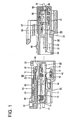
- a connector of this embodiment is provided with a housing 10, one or more female terminal fittings 40 and a detecting member 60, wherein the housing 10 is connectable with a mating housing 90 and the detecting member 60 is movable between a standby position SP (or first position) and a detection position DP (or second position) with respect to the housing 10.
- a standby position SP or first position
- a detection position DP or second position
- the male housing 90 is made e.g. of synthetic resin and includes a terminal accommodating portion 91 capable of at least partly accommodating one or more male terminal fittings 50 and a tubular receptacle 92 projecting forward on or from (preferably the front surface of) the terminal accommodating portion 91.
- One or more cavities 93 capable of at least partly accommodating the respective male terminal fittings 50 are formed in the terminal accommodating portion 91.
- one or more tabs 51 of the respective male terminal fittings 50 are arranged to project substantially forward from the front surface of the cavities 93, and a releasing piece 94 projects forward from the back wall of the receptacle 92.
- a lock portion 95 projects on or from the lateral (upper) surface of the receptacle 92.
- a retainer 96 for retaining the one or more male terminal fittings 50 is to be at least partly mounted in the terminal accommodating portion 91.
- This retainer 96 includes one or more terminal locking portions 97 for locking respective portions (preferably box portions) 52 of the male terminal fittings 50, and (preferably substantially sawtooth-shaped or pointed) projections 98 for biting in or engaging the insulation coatings of wires 55 connected with the male terminal fittings 50.
- the male terminal fittings 50 are primarily retained in the cavities 93 by the engagement of locking lances 54 formed in the (box) portions 52 preferably by cutting and bending with the inner walls of the cavities 94.
- the male terminal fittings 50 may be retained in the respective cavities 93 by locking portions (not shown) provided therein or thereon.
- the housing 10 is made e.g. of synthetic resin and includes a housing main body 11 (preferably substantially in the form of a flat block), at least one lock arm 12 provided at or on the lateral (upper) surface of the housing main body 11 and a fitting portion 13 at least partly surrounding the housing main body 11 as shown in FIG. 9 .
- One or more, e.g. three cavities 14 capable of at least partly accommodating the one or more respective female terminal fittings 40 are arranged in a row in the housing main body 11, preferably laterally in a row in the housing main body 11.
- one or more, preferably a pair of lateral (left and/or right) receiving portions 15 for detection project from the rear end of the housing main body 11.
- the wire holding member 17 includes (preferably substantially sawtooth-shaped or pointed) projections 18 for biting in or engaging the insulation coatings of wires 41, and movements of the wires 41 substantially in forward and backward directions are restricted by this biting or engaging action of the projections 18.
- An accommodating chamber 19 for a shorting terminal 42 is so formed in (preferably the front surface of) the housing main body 11 as to communicate at least with two cavities 14 adjacent to each other.
- the accommodating chamber 19 preferably also makes an opening in a side surface of the fitting portion 13, and the shorting terminal 42 can be mounted through this opening in the side surface.
- the shorting terminal 42 comes or can come into contact with the respective female terminal fittings 40 at least partly accommodated in the at least two cavities 14 laterally or from below to short the two or more terminal fittings 40 (see FIG. 1 ) preferably until a connecting operation of the two housings 10, 90 is completed.
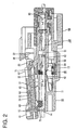
- the shorting terminal 42 preferably is pressed down (or away from the two or more terminal fittings 40) by the releasing piece 94 of the receptacle 92 to release the two or more terminal fittings 40 from the shorted state (see FIG. 3 ).
- the lock arm 12 is comprised of one or more, preferably a pair of lateral (left and/or right) leg portions 21 standing up from or projecting on the outer (upper) surface of the housing main body 11, one or more, preferably a pair of lateral (left and/or right) arm portions 22 extending (preferably both) substantially forward and/or backward from the upper ends of the (preferably both) leg portion(s) 21, a lower plate 23 preferably coupling the bottom end edges of the both arm portions 22, an upper plate 24 (preferably substantially in the form of a rectangular plate) preferably coupling the upper end edges of the both arms 22 and a lock main body 25 preferably coupling the front ends of the arm portions 22, and is pivotally displaceable (resiliently displaceable) upward and downward (or in a direction intersecting a connecting direction of the two connector housings 10, 90) like a seesaw with the (preferably both) leg portion(s) 21 as supporting point(s).
- a formation area of the lower plate 23 in forward and backward directions preferably is a range from a position behind the lock main body 25 to the rear ends of the lock portions 22, and the outer or upper plate 24 is arranged at the rear ends of the arm portions 22.
- Both the outer or upper plate 24 and the inner or lower plate 23 preferably are thin plates and substantially horizontally arranged in different levels or radial positions.
- One or more, preferably a pair of lateral (left and/or right) guide ribs 27 extending substantially in forward and backward directions (lengthwise direction of the lock arm 12 in a free state) are provided to project at or near the (preferably substantially opposite) lateral edge(s) of the arm portions 22, and one or more, preferably a pair of lateral (left and/or right) retaining projections 28 are provided to project at the (preferably substantially opposite) lateral edge(s) of the lower surface(s).
- the lower surface(s) of the guide rib(s) 27 and the upper surface(s) of the retaining projection(s) 28 is/are integrally or unitarily connected.
- the fitting portion 13 includes one or more, preferably a pair of lateral (left and/or right) side walls 31 standing up or projecting on or at the (preferably substantially opposite) side(s) of the lock arm 12.
- the fitting portion 13 preferably also includes a coupling wall 32 coupling the front ends of the upper edges of the opposite side walls 31.
- the outer surfaces of the housing 10 including the lock arm 12 preferably are entirely in a second color, specifically in a bright color such as yellow, and the entire external appearance thereof is seen uniformly in the bright color such as yellow before the detecting member 60 is assembled.
- Each female terminal fitting 40 substantially is narrow and long in forward and backward directions, wherein a front portion (preferably a substantially front half thereof) serves as a (preferably substantially tubular or box-shaped) connecting portion 43 and a rear portion (preferably a substantially rear half thereof) serves as a wire connection portion (preferably comprising a wire crimping portion 44 in the form of at least one open barrel).
- a locking lance 45 is formed in or on the connecting portion 43 preferably by cutting and bending.
- the female terminal fitting 40 at least partly inserted into the cavity 14 from an insertion side, preferably substantially from behind, is retained in the cavity 14 by the resilient engagement of the locking lance 45 with the inner wall of the cavity 14.
- the female terminal fitting 40 may be retained in the cavity 14 by a locking portion provided therein or thereon.
- the detecting member 60 is made e.g. of synthetic resin and includes a (preferably substantially block-shaped) operable portion 61 located at or near the rear end, one or more, preferably a pair of lateral (left and/or right) cantilever-shaped guide arms 62 extending substantially forward from the (preferably substantially opposite) end(s) of the operable portion 61, a covering portion 63 coupling the upper end edges of the (preferably both) guide arm(s) 62 and a cantilever-shaped detecting main body 64 located below or inward of the covering portion 63 and adjacent to guide arm(s) 62 (or preferably between the two guide arms 62) and extending substantially forward from the operable portion 61 as shown in FIG. 8 . As shown in FIG.
- one or more guide grooves 65 are so formed in the inner surface(s) of the (preferably both) guide arm(s) 62 as to extend in forward and backward directions.
- the guide grooves 65 are arranged such that openings thereof are faced inwardly.
- One or more, preferably a pair of lateral (left and/or right) retaining projections 66 are provided on the inner surfaces of the (preferably both) guide arm(s) 62 below the guide groove(s) 65.
- the covering portion 63 preferably substantially is in the form of a flat plate at least partly covering a portion (preferably substantially the rear half) of the housing main body 11 and includes one or more, preferably a pair of lateral (left and/or right) contact pieces 67 projecting forward from the front end edge thereof.
- One or more, preferably a pair of lateral (left and/or right) through holes 68 are formed at positions near the (preferably substantially opposite) lateral edge(s) of the covering portion 63.
- the (preferably both) through hole(s) 68 of the covering portion 63 preferably substantially are rectangular holes longer or elongate in forward and backward directions, and the corresponding retaining projection(s) 66 can be seen through the (preferably both) through hole(s) 68 in an isolated state before being assembled.
- the covering portion 63 is also formed with a (preferably single) window portion 69 (corresponding to a preferred "opening") at a widthwise intermediate position (preferably substantially a widthwise center position) near the rear end edge.
- the window portion 69 of the covering portion 63 preferably is a loop hole, specifically a round hole.
- the detecting member 60 When the detecting member 60 is in a state before being assembled or in a standby state (standby position SP), a part of the detecting member 60, specifically, the upper surface of the detecting main body 64 can be seen through the window portion 69. When the detecting member 60 is at the detection position DP, a part of the housing 10, specifically the upper surface of the upper plate 24 can be seen through the window portion 69.
- the detecting main body 64 preferably substantially is in the form of a plate narrow and long in forward and backward directions and is resiliently deformable upward and downward, and a contact projection 71 projecting downward or inwardly is provided at or near the front end thereof.
- a front end portion of the detecting main body 64 is made thinner than a base end portion thereof connected with the operable portion 61, thereby enabling smooth deformations of the front end portion and/or increasing the strength of the base end portion.
- the bottom end of the operable portion 61 is located slightly below the lower surface of the detecting main body 64, and the front end edge of the bottom end of the operable portion 61 constitutes one or more connection detecting portions 72.
- the outer surfaces of the detecting member 60 preferably are entirely in a first color different from the second color, specifically in a darker color such as blue, so that the entire external appearance thereof is seen uniformly in the first color (blue) before being assembled with the lock arm 12.
- Such a detecting member 60 is assembled with the lock arm 12 (meaning the same as "with the housing 10") preferably substantially from behind, and the detecting main body 64 at least partly enters the mount space 26 as the detecting member 60 is assembled.
- the one or more guide ribs 27 and the one or more guide grooves 65 are engaged, whereby the detecting member 60 is slid forward with respect to the lock arm 12 and the guide arms 62 are resiliently deformed outwardly substantially in width direction by the interference of the retaining projections 28, 66.
- the retaining projections 66 of the detecting member 60 are engaged with the retaining projections 28 of the lock arm 12 from front, thereby retaining the detecting member 60, and/or the contact projection 71 is engaged with the lock main body 25 from behind, thereby preventing the detecting member 60 from moving any further forward.
- the detecting member 60 is held or located at the standby position SP.
- the detecting main body 64 is held between the upper plate 24 and the lower plate 23 and/or at least partly between the left and right arm portions 22, and the upper plate 24 is held at least partly between the detecting main body 64 and the covering portion 63, whereby the detecting member 60 is united with the lock arm 12 to preferably be displaceable substantially like a seesaw.
- a space between the lower surface of the covering portion 63 and the upper surface of the detecting main body 64 serves as a sliding space 39 for the upper plate 24, and a dimension thereof preferably is set substantially equal to or slightly larger than the thickness of the upper plate 24.
- the detecting member 60 is held or positioned at the standby position SP with respect to the lock arm 12.
- the operable portion 61 projects more backward than the rear surface of the housing main body 11 and the upper surfaces of the arm portions 22 are or can be seen or detected through the through holes 68 and the upper surface of the detecting main body 64 is or can be seen or detected through the window portion 69 when the detecting member 60 is viewed from above.
- a background color seen through the window portion 69 preferably is the same first color (blue) as a peripheral part of the window portion 69 in this case.
- a background color seen through the through holes 68 is the second color (preferably yellow) as the color of the housing main body 11 and remains the second color (yellow) even when the detecting member 60 is successively moved.
- the receptacle 92 of the mating housing 90 is at least partly inserted between the housing main body 11 and the fitting portion 13.
- the lock main body 25 of the lock arm 12 moves onto the lock portion 95 of the mating housing 90 as shown in FIG. 2 , whereby the lock arm 12 and the detecting member 60 are displaced to extend obliquely upward or outward toward the front and the connection detecting portions 72 of the detecting member 60 are displaced inwardly or downwardly to face the receiving portions 15 for detection of the housing main body 11 from behind.
- the connecting operation of the two housings 10, 90 should be finished in an incomplete way (e.g.
- connection detecting portions 72 come into contact with the receiving portions 15 for detection to prevent a forward movement of the detecting member 60. Since the contact projection 71 is kept engaged with the lock main body 25, the forward movement of the detecting member 60 is (preferably also) prevented by this.
- the lock main body 25 passes the lock portion 95, whereby the lock arm 12 returns towards or to its free state by its resilient restoring force to engage the lock main body 25 with the lock portion 95.
- the two housings 10, 90 are inseparably held.
- the lower surface of the contact projection 71 is substantially in contact with the upper surface of the lock portion 95, whereby the detecting main body 64 is resiliently deformed upwardly or outwardly relative to the lock arm 12.
- the operable portion 61 of the detecting member 60 is displaced upwardly or outwardly together with the lock arm 12, thereby disengaging the connection detecting portions 72 from the receiving portions 15 for detection.
- the contact projection 71 and the lock main body 25 are disengaged to permit a movement of the detecting member 60 towards or to the detection position DP.
- the background color seen through the window portion 69 remains the second color (yellow) since the position of the detecting member 60 relative to the lock arm 12 continues to be the standby position SP.
- the detecting member 60 is slid or moved toward the detection position DP with respect to the lock arm 12.
- the contact projection 71 passes the lock portion 95 and the lock main body 25, whereby the detecting main body 64 is resiliently at least partly restored.
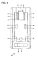
- the contact projection 71 is engaged with the lock main body 25 from front as shown in FIG. 6 .
- the front end(s) of the (both) contact piece(s) 67 come(s) into contact with the coupling wall 32 from behind to prevent any further forward movement of the detecting member 60.
- the detecting member 60 is held at the detection position DP while preferably being prevented from moving forward and backward with respect to the lock arm 12 as shown in FIGS.
- the upper plate 24 of the lock arm 12 is relatively displaced backward with respect to the detecting member 60 in the sliding space 39 between the detecting main body 64 and the covering portion 63 and gradually appears in the window portion 69 preferably immediately before the detecting member 60 reaches the detection position DP.
- the upper plate 24 comes to appear in the entire window portion 69. Accordingly, if an operator looks inside the window portion 69 in this state, the second color (yellow color) of the upper plate 24 (housing 10) can be seen through the window portion 69.
- the detecting member 60 is kept at the standby position SP, the upper plate 24 is located before the window portion 69 and does not correspond to the window portion 69, wherefore only the upper surface of the detecting main body 64 can be seen through the window portion 69 via the sliding space 39 and the background color seen through the window portion 69 is the same first color (blue color) as the peripheral part of the window portion 69. Accordingly, it can be judged that the detecting member 60 has not been moved if there is no change in the background color seen through the window portion 69 and, in this case, the detecting member 60 is pushed to the detection position DP anew.
- this embodiment has the following effects.
- the background color seen through the window portion 69 is a different color than the one seen at the standby position SP, wherefore the arrival of the detecting member 60 at the detection position DP can be (preferably visually) clearly detected. As a result, it can be prevented to forget to move the detecting member 60, thereby being able to improve the reliability of the connection detecting function of the connector.
- the color in the window portion 69 (color of the upper surface of the detecting main body 64) and the color outside the window portion 69 (color of the upper surface of the covering portion 63) can be the same color (e.g. blue color).
- the operator needs not remember the background colors seen through the window portion 69 at the standby position SP and the detection position DP and can judge the arrival of the detecting member 60 at the detection position DP by the fact that the color (yellow in this embodiment) different from that of the peripheral part of the window portion 69 has appeared in the window portion 69. Therefore, an erroneously confirming possibility of the operator decreases and the reliability of the connection detecting function can be further improved.
- the detecting main body 64 of the lock arm 12 Since the detecting main body 64 of the lock arm 12 is seen through the window portion 69 at the detection position DP, a condition such as a defective state of the detecting main body 64 can also be confirmed, wherefore the quality of the lock arm 12 can also be improved.
- the detecting member 60 preferably is entirely in the first color (blue) and the housing 10 preferably is entirely in the second color (yellow) different from the first color, it is not necessary to color-separate the upper plate 24 and the detecting main body 64 from surrounding parts, wherefore production is easier.
- the window portion 69 is located at the easily detectable or seeable position of the detecting member 60 in the widthwise intermediate part (preferably substantially central part) of the outer or upper surface of the connector and near the operable portion 61 and has an easily seeable shape (looped opening), the visibility thereof is good.
- a detecting member 60 is so assembled with a lock arm 12 of a housing 10 as to be movable between a standby position SP and a detection position DP.
- the detecting member 60 is permitted to move from the standby position SP to the detection position DP when the housing 10 is properly connected with a mating housing 90, and a movement thereof to the detection position DP is prevented in a state where the housing 10 is partly connected with the mating housing 90.
- the detecting member 60 is formed with at least one window portion 69.
- a detecting main body 64 of the detecting member 60 is at least partly seen or detectable through the window portion 69 at the standby position SP, whereas an upper plate 24 of the lock arm 12 is at least partly seen or detectable therethrough at the detection position DP.
- the detecting member 60 is in a first color and the housing is in a second color different from the first color.
- a connector of this embodiment is provided with a first housing 110 having one or more male terminal fittings 111 at least partly mounted therein and a second housing 120 having one or more female terminal fittings 121 at least partly mounted therein. It should be noted that, in the following description, forward and backward directions are the same directions as those parallel to a connecting direction of the two housings 110, 120 and a sliding or movement direction of a connection detecting member 133 to be described later from an initial position to a detection position.
- the first housing 110 is made e.g. of synthetic resin and includes a tubular receptacle 112 projecting forward (substantially same direction as the connecting direction with the second housing 120).
- a lock projection 113 is formed to project from the lateral (upper) surface (outer surface) of the lateral (upper) wall of the receptacle 112.
- the second housing 120 is made e.g. of synthetic resin and is an integral or unitary assembly of a block-shaped terminal holding portion 122 and a tubular fitting portion 123 (preferably substantially in the form of a rectangular tube) at least partly surrounding a front portion (preferably a substantially a front half area) of the terminal holding portion 122, wherein the female terminal fittings 121 are to be at least partly accommodated in the terminal holding portion 122.
- a lock arm 124 extending substantially in forward and backward directions is integrally or unitarily formed on the lateral (upper) surface (outer surface) of the terminal holding portion 122.
- the lock arm 124 is an integral or unitary assembly of one or more, preferably a pair of lateral (left and/or right) arm portions 125 extending substantially in forward and backward directions, a lock portion 126 provided on the arm portion 125, preferably connecting the front ends of the both arm portions 125, a (preferably substantially plate-like) coupling portion 127 coupling the rear ends of the both arm portions 125, one or more, preferably a pair of leg portions 128 projecting from (preferably substantially central positions of) the lower or inner surfaces of the both arm portions 125, and a lower plate 129 coupling the bottom end edges of the both arm portions 125 and is supported on the terminal holding portion 122 at the leg portions 128.
- Such a lock arm 124 is in a locking posture where the both arms 125 are extending substantially in forward and backward directions (directions substantially parallel to connecting and separating directions of the two housings 110, 120) in a free state where the lock arm is not resiliently displaced, and is resiliently displaceable substantially like a seesaw to an unlocking posture reached by displacing a front end side thereof upward or outward (direction at an angle different from 0° or 180°, preferably substantially orthogonal to forward and backward directions) with the leg portions 128 substantially as supporting points.
- One or more guide ribs 130 extending substantially in the lengthwise direction of the arm portions 125 are formed at or near the outer lateral edges of the arm portions 125, and one or more stoppers 131 are formed on the lower surfaces of the both guide ribs 130.
- the lower plate 129 preferably is formed to extend from the rear ends of the arm portions 125 to a position slightly behind the front ends (lock portion 126) of the arm portions 125. There is an open space between the front end edge of the lower plate 129 and the lock portion 126, into which space the lock projection 113 is at least partly fittable or insertable.
- An upper wall 123A of the tubular fitting portion 123 is formed with an opening 123B preferably by cutting away an area thereof excluding the opposite left and/or right edge portions and a front end edge portion, and the lock arm 124 is exposed upward through this opening 123B.
- connection detecting member 133 made e.g. of synthetic resin is mounted in the second housing 120.
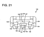
- the connection detecting member 133 preferably is an integral or unitary assembly of a pair of left and right narrow and long side walls 134 extending substantially in forward and backward directions, an operable portion 135 coupling the rear ends of the both side walls 134, a bar-shaped supporting portion 136 projecting forward (in parallel with the side walls 134) in a space between the opposite side walls 134, a resilient piece 137 extending further forward (direction extending from the initial position toward the detection position) from the front end (extending end) of the supporting portion 136 and a (preferably substantially plate-like) restricting portion 138 coupling the upper edges of the both side walls 134.
- One or more guide grooves 139 substantially parallel to the lengthwise direction of the side walls 134 are formed in the inner side surface(s) of the (preferably both) side wall(s) 134, and one or more retaining projections 140 are formed to project inwardly from (preferably substantially central positions of) the inner side surfaces of the side walls 134 substantially in forward and backward directions.
- the resilient piece 137 has a smaller vertical thickness than the supporting portion 136, the upper surface of the resilient piece 137 preferably is substantially in flush with and continuous with that of the supporting portion 136, and the lower surface of the resilient piece 137 is located above that of the supporting portion 136.
- a locking portion 141 to be engaged with the lock portion 126 of the lock arm 124 is formed at or near the front end of the resilient piece 137.
- the locking portion 141 is comprised of a projecting end 142 as the front end (extending end) of the resilient piece 137, a touching portion 143 projecting downward or inward from a position slightly behind the projecting end 142, and a cut-away portion 144 defined by or at the lower or inner surface of the projecting end 142 and the front surface of the touching portion 143.
- a resilient piece 137 is resiliently deformable to be curved upward or outward between a base end (rear end) substantially continuous with the front end of the supporting portion 136 and the locking portion 141 and resiliently displaceable so that the locking portion 141 side is displaced upward or outward with the base end substantially as a supporting point.
- the front end of the resilient piece 137 is located behind the front ends of the side walls 134.
- the restricting portion 138 is connected with the upper end edges of the one or more, preferably pair of side walls 134 at an angle different from 0° or 180°, preferably substantially at right angles and formed to continuously extend substantially in forward and backward directions from the rear ends of the both side walls 134 (front end of the operable portion 135) to a position slightly behind the front ends of the side walls 134.
- the front end position of the restricting portion 138 is located slightly behind the front end (projecting end 142) of the locking portion 141 of the resilient piece 137 and preferably substantially at the same position as the touching portion 143 in forward and backward directions.
- a formation range of the restricting portion 138 substantially in forward and backward directions preferably includes an area corresponding to at least a lengthwise (forward and backward directions) middle part of the resilient piece 137 out of a curvable area from the base end of the resilient piece 137 to the locking portion 141, i.e. is limited to a range of an area not corresponding to the extending end (locking portion 141) of the resilient piece 137 preferably in the substantially entire length of the resilient piece 137. Accordingly, the front end of the resilient piece 137 (particularly the range including the projecting end 142 and the substantially front half of the touching portion 143 of the locking portion 141) projects more forward than the front end of the restricting portion 138.
- the resilient piece 137 Since the resilient piece 137 has a most area thereof excluding the front end covered by the restricting portion 138 from above (from the outer side), the resilient piece 137 is protected from the interference of external matters by the restricting portion 138. Further, a space for permitting upward resilient displacement and curved deformation of the resilient piece 137 preferably is defined between the lower surface of the restricting portion 138 and the upper surface of the resilient piece 137. An arcuate contact portion 145 is formed at or near the lower edge of the end (front end) of the restricting portion 138 at the substantially same side as the extending end of the resilient piece 137.
- the restricting portion 138 is also formed with a (preferably single) window portion 169 (corresponding to a preferred "opening") at a widthwise intermediate position (preferably substantially a widthwise center position) near the rear end edge.
- the window portion 169 of the restricting portion 138 preferably is a loop hole, specifically a round hole.
- connection detecting member 133 is assembled with the lock arm 124 (preferably substantially from behind) by being slid or displaced with the guide groove(s) 139 engaged with the guide rib(s) 130.
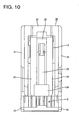
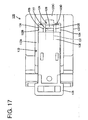
- the connection detecting member 133 reaches the initial or stand-by position SP, the retaining projections 140 pass the stoppers 131 to be engaged with the stoppers 131 from front as shown in FIG. 16 , thereby preventing a backward movement of the connection detecting member 133, and the touching portion 143 at the front end of the resilient piece 137 comes into engagement with the lock portion 126 from behind, thereby preventing any further forward movement of the connection detecting member 133.
- the connection detecting member 133 is held at the initial or stand-by position DP (see FIGS. 12 and 17 ). In other words, the connection detecting member 133 has its forward (toward the detecting position DP) movement prevented.
- the projecting end 142 of the resilient piece 137 is placed on the outer or upper surface of the lock portion 126, and the cut-away portion 144 is obliquely fitted to the lock portion 126 from an upper rear side.
- the supporting portion 136 is vertically held between the lower plate 129 and the coupling portion 127, and the coupling portion 127 is vertically held between the supporting portion 136 and the restricting portion 138, whereby the connection detecting member 133 has vertical movements thereof relative to the lock arm 124 prevented.
- the supporting portion 136 is held at least partly between the pair of arm portions 125 and the left and right side walls 134 are held in contact with the lateral (left and/or right) inner wall surface(s) of the tubular fitting portion 123, whereby the connection detecting member 133 is prevented from laterally moving relative to the lock arm 124 and the second housing 120.
- the upper surface of the restricting portion 138 preferably substantially is at the same height as or slightly lower than that of the upper wall 123A of the tubular fitting portion 123. Therefore, there is no likelihood that external matters collide with the restricting portion 138 from above.
- connection detecting member 133 held or positioned at the initial position SP can be moved forward (substantially in parallel with the connecting direction of the two housings 110, 120) while being guided by the guide groove(s) 139 and the guide rib(s) 130.
- any further forward movement of the connection detecting member 133 preferably is prevented when the bottom end of the touching portion 143 slides on the upper surface of the lock portion 126 and the front end of the restricting portion 138 comes into contact with a front stop portion 123D on a front edge portion 123C of the tubular fitting portion 123.
- the touching portion 143 passes the lock portion 126, the resilient piece 137 is resiliently at least partly restored and the touching portion 143 is engaged with the lock portion 126 from front, whereby a backward (toward the initial position SP) of the connection detecting member 133 is prevented to hold or position the connection detecting member 133 at the detecting position DP.
- connection detecting member 133 located at the detecting position DP, the front ends of the side walls 134 preferably are in contact with the front edge portion 123C from the lower side (from the inner side).
- an upward or outward displacement of the front end of the connection detecting member 133 i.e. a resilient displacement of the lock arm 124 to the unlocking posture, is prevented.
- connection detecting member 133 located at the detection position DP there is no likelihood that external matters collide with the restricting portion 138 from above since the upper surface of the restricting portion 138 is at the same height as or slightly lower than that of the upper wall 123A of the tubular fitting portion 123 similar to at the initial position.
- the receptacle 112 is at least partly fitted or inserted on the terminal holding portion 122 and at least partly inserted into the tubular fitting portion 123. Then, as shown in FIG. 13 , the lock portion 126 moves onto the lock projection 113 and, accordingly, the lock arm 124 is resiliently displaced to the unlocking posture. At this time, the connection detecting member 133 also inclines its posture to displace the front end side thereof upward while being united with the lock arm 124. However, since the lock portion 141 is held engaged with the lock portion 126, the connection detecting member 133 cannot move to the detecting position DP.
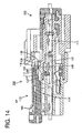
- the two housings 110, 120 are properly connected as shown in FIG. 14 , the lock portion 126 passes the lock projection 113, and the lock arm 124 is resiliently at least partly restored to the locking posture, whereby the two housings 110, 120 are inseparably locked into each other by the engagement of the lock portion 126 and the lock projection 113.
- the lock arm 124 is resiliently restored, a part of the connection detecting member 133 except the resilient piece 137 is returned towards or to its original posture together with the lock arm 124.
- the resilient piece 137 is resiliently displaced upward or outward relative to the side walls 134 and the restricting portion 138 with the touching portion 143 placed on the outer (upper) surface of the lock projection 113.
- the contact portion 145 at the front end of the restricting portion 138 may collide with the upper surface of the locking portion 141 from above or outside. Since this position of collision is located at a part of the locking portion 141 in forward and backward directions where the thickness (vertical dimension) is largest, i.e. a part where the touching portion 143 is formed, there is no likelihood of deforming the locking portion 141 held between the restricting portion 138 and the lock projection 113.
- connection detecting member 133 In the state where the two housings 110, 120 are properly connected and the connection detecting member 133 is located at the initial position SP, the locking portion 141 and the lock portion 126 are disengaged from each other by an upward or outward movement of the touching portion 143 relative to the lock portion 126. Thus, the connection detecting member 133 is permitted to move forward. Further, since the upper surface of the lock projection 113 in contact with the locking portion 141 and that of the lock portion 126 are located at the substantially same height so as to be substantially flush with each other, the locking portion 141 can slide in such a manner as to move from the outer (upper) surface of the lock projection 113 onto that of the lock portion 126. In other words, the connection detecting member 133 can slide from the initial position SP to the detecting position DP.
- connection detecting member 133 In this state, if the operable portion 135 is pushed from behind or operated to move the connection detecting member 133 towards or to the detecting position DP, the touching portion 143 passes the lock portion 126 as shown in FIG. 15 , wherefore the resilient piece 137 is resiliently restored and the touching portion 143 is engaged with the lock portion 126 from front.
- the connection detecting member 133 has its backward (toward the initial position SP) returning movement prevented and is held or positioned at the detecting position DP.
- connection detecting member 133 held at the initial position SP is prevented from being pushed to the detecting position DP in the state where the two housings 110, 120 are not connected yet.
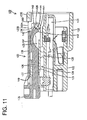
- the resilient piece 137 is so resiliently deformed as to curve the part thereof between the base end (rear end) and the locking portion 141 as the part to be engaged with the lock portion 126 upward (direction opposite to the lock projection 113) as shown in FIG. 11 . If this resilient deformation amount increases, a forward inclined angle of the front end of the resilient piece 127 increases.
- the front end of the projecting end 142 comes substantially into contact with the upper surface of the lock portion 126 to displace the touching portion 143 (upward or outward) relative to the lock portion 126 and, consequently, the touching portion 143 is disengaged from the lock portion 126. Then, the state of preventing a forward movement of the connection detecting member 133 by the locking portion 141 of the resilient piece 137 is released, wherefore the connection detecting member 133 can move to the detecting position DP.
- the restricting portion 138 is provided above the resilient piece 137 and an excessive curved deformation of the resilient piece 137 preferably is prevented by this restricting portion 138.
- the locking portion 141 is held engaged with the lock portion 126 to prevent a forward movement of the connection detecting member 133. In this way, a movement of the connection detecting member 133 to the detecting position is prevented in the state where the two housings 110, 120 are not connected yet.
- the lengthwise intermediate part (preferably the substantially lengthwise middle part) of the resilient piece 137 is maximally displaced when the resilient piece 137 is curved.
- the restricting portion 138 is formed over the range including the area corresponding to the lengthwise intermediate part (preferably the substantially lengthwise middle part) of the resilient piece 137 in this embodiment. Therefore, the excessive curved deformation of the resilient piece 137 can be effectively prevented.
- the resilient piece 137 interfering with the lock projection 113 inclines its posture and is displaced toward the restricting portion 138.
- a displacement amount of the resilient piece 137 at this time is largest at the extending end (front end) of the resilient piece 137.
- the formation range of the restricting portion 138 is set in the area of the resilient piece 137 excluding the extending end in this embodiment. Therefore, there is no likelihood of hindering the displacement of the resilient piece 137 due to the interference of the extending end of the resilient piece 137 with the restricting portion 138.
- the extending end (front end) of the resilient piece 137 comes into contact with the contact portion 145 formed at the front end edge of the restricting portion 138 (end edge at the substantially same side as the extending end of the resilient piece 137). If this contact portion 145 is angular like an edge, the contact portion 145 and the resilient piece 137 may be deformed. In this respect, since the contact portion 145 is arcuate in this embodiment, deformations of the contact portion 145 and the resilient piece 137 can be prevented.
- the restricting portion 138 is formed integral or unitary to the connection detecting member 133 as a formation base of the resilient piece 137, there is no likelihood of disrupting the positional relationship of the resilient piece 137 and the restricting portion 138.
- the restricting portion 138 is connected with the upper edges of the pair of side walls 134 substantially at right angles and formed to connect this pair of side walls 134, the deflection strength of the restricting portion 138 is higher as compared with the case where the restricting portion in the form of a single plate singly extends. Therefore, the curved deformation of the resilient piece 137 can be reliably restricted.
- connection detecting member 133 to prevent a connection detecting member from moving from an initial position to a detection position in a state where two housings are not connected yet, if an external force is exerted to a connection detecting member 133 to move it toward a detection position DP and a resilient piece 137 is curved and deformed in a state where two housings 110, 120 are not connected yet, the resilient piece 137 comes substantially into contact with a restricting portion 138 before being disengaged from a lock arm 124 to prevent any further curved deformation of the resilient piece 137.
- the disengagement of the resilient piece 137 from the lock arm 124 due to its curved deformation can be prevented. Therefore, a movement of the connection detecting member 133 from an initial position SP to the detection position DP can be prevented in the state where the two housings 110, 120 are not connected yet.
Claims (13)
- Connecteur comprenant :un logement (10 ; 120) capable d'au moins partiellement recevoir au moins une garniture terminale (40 ; 121), etau moins un élément de détection (60 ; 133) devant être monté avec le logement (10 ; 120) de manière à pouvoir être déplacé entre une position de veille (SP) et une position de détection (DP), autorisé à se déplacer de la position de veille (SP) vers la position de détection (DP) si le logement (10 ; 120) est correctement connecté à un logement conjugué (90 ; 110) et empêché de se déplacer vers la position de détection (DP) dans un état où le logement (10 ; 120) est partiellement connecté au logement conjugué (90 ; 110),dans lequel l'élément de détection (60 ; 133) est formé d'au moins une ouverture (69; 169),caractérisé en ce qu'une couleur d'arrière-plan qui peut être vue à travers l'ouverture (69 ; 169) diffère lorsque l'élément de détection (60 ; 133) est positionné au niveau de la position de veille (SP) et au niveau de la position de détection (DP),dans lequel une partie correspondante (64 ; 136) de l'élément de détection (60 ; 133) peut être vue à travers l'ouverture (69 ; 169) lorsque l'élément de détection (60 ; 133) est positionné au niveau de la position de veille (SP) et une partie correspondante (24 ; 127) du logement (10 ; 120) peut être vue à travers l'ouverture (69 ; 169) lorsque l'élément de détection (60 ; 133) est positionné au niveau de la position de détection (DP).
- Connecteur selon la revendication 1, dans lequel :le logement (10 ; 120) inclut au moins un bras de verrouillage (12 ; 127) pour maintenir un état connecté au logement conjugué (90 ; 110), etune partie correspondante (24 ; 127) du bras de verrouillage (12 ; 127) peut être vue à travers l'ouverture (69 ; 169) lorsque l'élément de détection (60 ; 133) est positionné au niveau de la position de détection (DP).
- Connecteur selon une ou plusieurs des revendications précédentes, dans lequel l'élément de détection (60 ; 133) est d'une première couleur et le logement (10 ; 120) est d'une seconde couleur différente de la première couleur.
- Connecteur selon une ou plusieurs des revendications précédentes, comprenant :le logement (120) pouvant être connecté à un logement conjugué (110), le logement (120) incluant au moins un bras de verrouillage (124),au moins un élément de détection de connexion (133) prévu dans ou sur le logement (120) et pouvant coulisser entre une position initiale (SP) et une position de détection (DP) dans des directions essentiellement parallèles à une direction de connexion du logement (120) avec le logement conjugué (110), etune pièce élastique (137) s'étendant depuis l'élément de détection de connexion (133) dans une direction vers la position de détection (DP),dans lequel :la pièce élastique (137) est en contact avec le bras de verrouillage (124) pour empêcher un mouvement coulissant de l'élément de détection de connexion (133) vers la position de détection (DP) et engagée avec le bras de verrouillage (124) de manière à pouvoir être déplacée avec le bras de verrouillage (124) dans un état où l'élément de détection de connexion (133) est situé au niveau de la position initiale (SP),le bras de verrouillage (124) est déformé de manière élastique dans une direction coupant la direction de connexion des deux logements par interférence avec une saillie de verrouillage (113) du logement conjugué (110) dans un processus de connexion du logement (120) au logement conjugué (110),lorsque les deux logements (120, 110) sont correctement connectés, le bras de verrouillage (124) passe la saillie de verrouillage (113) et est restauré au moins partiellement de manière élastique pour être engagé avec la saillie de verrouillage (113) de manière à empêcher la séparation des deux logements (120, 110), et la pièce élastique (137) est désengagée du bras de verrouillage (124) par interférence avec la saillie de verrouillage (113), moyennant quoi le mouvement de l'élément de détection de connexion (133) vers la position de détection (DP) est permis.
- Connecteur selon la revendication 4, dans lequel une portion de restriction (138) est prévue pour empêcher une déformation courbée excessive de la pièce élastique (137) vers un côté opposé à la saillie de verrouillage (113) avec la pièce élastique (137) engagée avec le bras de verrouillage (124) dans l'état où l'élément de détection de connexion (133) est situé au niveau de la position initiale (SP).
- Connecteur selon la revendication 5, dans lequel la portion de restriction (138) est formée dans une plage correspondant à au moins une partie centrale en longueur de la pièce élastique hors d'une zone pouvant être courbée de la pièce élastique (137) depuis une extrémité de base de celle-ci vers une portion de verrouillage (143) devant être engagée avec le bras de verrouillage (124).
- Connecteur selon la revendication 5 ou 6, dans lequel la portion de restriction (138) est formée dans une plage d'une zone ne correspondant pas à une extrémité d'extension de la pièce élastique (137) dans la longueur entière de la pièce élastique (137).
- Connecteur selon la revendication 7, dans lequel une portion de contact arquée ou conique est formée au niveau d'un bord d'extrémité de la portion de restriction (138) du même côté que l'extrémité d'extension de la pièce élastique (137).
- Connecteur selon une ou plusieurs des revendications précédentes 4 à 8, dans lequel la portion de restriction (138) est formée intégralement ou de manière unitaire avec l'élément de détection de connexion (133).
- Connecteur selon la revendication 9, dans lequel :l'élément de détection de connexion (133) inclut une paire de parois latérales (134) situées sur les côtés opposés de la pièce élastique (137), etla portion de restriction (138) est connectée à la paire de parois latérales (134),de préférence à des portions de bord de celles-ci, à un angle différent de 0° ou 180°, de préférence essentiellement à des angles droits et formée pour connecter la paire de parois latérales (134).
- Agencement de connecteur comprenant un connecteur selon une ou plusieurs des revendications précédentes et un connecteur conjugué pouvant être connecté à celui-ci.
- Procédé de connexion d'un connecteur à un connecteur conjugué, comprenant les étapes consistant à :fournir un logement (10 ; 120) capable d'au moins partiellement recevoir au moins une garniture terminale (40 ; 121),fournir un logement conjugué (90 ; 110), etmonter au moins un élément de détection (60 ; 133) avec le logement (10 ; 120) de manière à pouvoir être déplacé entre une position de veille (SP) et une position de détection (DP), autorisé à se déplacer de la position de veille (SP) vers la position de détection (DP) si le logement (10 ; 120) est correctement connecté à un logement conjugué (90 ; 110) et empêché de se déplacer vers la position de détection (DP) dans un état où le logement (10 ; 120) est partiellement connecté au logement conjugué (90 ; 110),caractérisé en ce queaprès connexion du logement (10 ; 120) et du logement conjugué (90 ; 110), la connexion est vérifiée en confirmant une couleur d'arrière-plan qui peut être vue à travers au moins une ouverture (69 ; 169) formée dans l'élément de détection (60, 133), dans lequel la couleur d'arrière-plan qui peut être vue à travers l'ouverture (69 ; 169) diffère lorsque l'élément de détection (60 ; 133) est positionné au niveau de la position de veille (SP) et au niveau de la position de détection (DP),dans lequel une partie correspondante (64 ; 136) de l'élément de détection (60 ; 133) est vue à travers l'ouverture (69 ; 169) lorsque l'élément de détection (60 ; 133) est positionné au niveau de la position de veille (SP) et une partie correspondante (24 ; 127) du logement (10 ; 120) est vue à travers l'ouverture (69 ; 169) lorsque l'élément de détection (60 ; 133) est positionné au niveau de la position de détection (DP).
- Procédé selon la revendication 12, comprenant en outre une étape consistant à maintenir un état connecté au logement conjugué (90 ; 110) au moyen d'au moins un bras de verrouillage (12 ; 127),
dans lequel une partie correspondante (24 ; 127) du bras de verrouillage (12 ; 127) est vue à travers l'ouverture (69 ; 169) lorsque l'élément de détection (60 ; 133) est positionné au niveau de la position de détection (DP).
Priority Applications (1)
| Application Number | Priority Date | Filing Date | Title |
|---|---|---|---|
| EP10008536A EP2249440B1 (fr) | 2007-08-01 | 2008-07-25 | Connecteur, assemblage de connecteur et procédé de connexion |
Applications Claiming Priority (2)
| Application Number | Priority Date | Filing Date | Title |
|---|---|---|---|
| JP2007200569A JP5119788B2 (ja) | 2007-08-01 | 2007-08-01 | コネクタ |
| JP2007209429A JP5181573B2 (ja) | 2007-08-10 | 2007-08-10 | コネクタ |
Related Child Applications (1)
| Application Number | Title | Priority Date | Filing Date |
|---|---|---|---|
| EP10008536.4 Division-Into | 2010-08-16 |
Publications (3)
| Publication Number | Publication Date |
|---|---|
| EP2020706A2 EP2020706A2 (fr) | 2009-02-04 |
| EP2020706A3 EP2020706A3 (fr) | 2009-02-11 |
| EP2020706B1 true EP2020706B1 (fr) | 2011-10-26 |
Family
ID=39855279
Family Applications (2)
| Application Number | Title | Priority Date | Filing Date |
|---|---|---|---|
| EP10008536A Active EP2249440B1 (fr) | 2007-08-01 | 2008-07-25 | Connecteur, assemblage de connecteur et procédé de connexion |
| EP08013446A Active EP2020706B1 (fr) | 2007-08-01 | 2008-07-25 | Connecteur, assemblage de connecteur et procédé de connexion |
Family Applications Before (1)
| Application Number | Title | Priority Date | Filing Date |
|---|---|---|---|
| EP10008536A Active EP2249440B1 (fr) | 2007-08-01 | 2008-07-25 | Connecteur, assemblage de connecteur et procédé de connexion |
Country Status (4)
| Country | Link |
|---|---|
| US (1) | US7591668B2 (fr) |
| EP (2) | EP2249440B1 (fr) |
| KR (2) | KR100987484B1 (fr) |
| CN (1) | CN102064432B (fr) |
Families Citing this family (44)
| Publication number | Priority date | Publication date | Assignee | Title |
|---|---|---|---|---|
| JP4636050B2 (ja) * | 2007-04-27 | 2011-02-23 | 住友電装株式会社 | コネクタ |
| JP2009004318A (ja) * | 2007-06-25 | 2009-01-08 | Sumitomo Wiring Syst Ltd | コネクタ |
| TWI359538B (en) * | 2008-07-01 | 2012-03-01 | Delta Electronics Inc | Electrical connector with latching device |
| JP5341477B2 (ja) * | 2008-11-04 | 2013-11-13 | 矢崎総業株式会社 | コネクタ |
| JP5511464B2 (ja) * | 2010-03-26 | 2014-06-04 | 矢崎総業株式会社 | 基板接続用コネクタの嵌合確認構造 |
| JP5771075B2 (ja) * | 2010-12-28 | 2015-08-26 | 矢崎総業株式会社 | 光コネクタ |
| JP5614317B2 (ja) | 2011-02-10 | 2014-10-29 | 住友電装株式会社 | コネクタ |
| JP5488839B2 (ja) * | 2011-05-12 | 2014-05-14 | 第一精工株式会社 | コネクタ装置 |
| JP5711096B2 (ja) * | 2011-10-24 | 2015-04-30 | モレックス インコーポレイテドMolex Incorporated | コネクタ |
| JP5817457B2 (ja) * | 2011-11-18 | 2015-11-18 | 住友電装株式会社 | コネクタ |
| US8678846B2 (en) * | 2012-03-28 | 2014-03-25 | Tyco Electronics Corporation | Electrical connector with connector position assurance device |
| TW201415794A (zh) * | 2012-10-09 | 2014-04-16 | Issc Technologies Corp | 可切換式濾波電路及其操作之方法 |
| ITTO20120904A1 (it) * | 2012-10-16 | 2014-04-17 | Tyco Electronics Amp Italia Srl | Connettore elettrico con elemento di assicurazione della posizione del connettore |
| US9160095B2 (en) | 2013-02-28 | 2015-10-13 | Yazaki North America, Inc. | Connector assembly with connector position assurance stabilizer |
| JP2015060628A (ja) * | 2013-09-17 | 2015-03-30 | 住友電装株式会社 | コネクタ |
| JP6025062B2 (ja) * | 2013-10-04 | 2016-11-16 | 住友電装株式会社 | コネクタ |
| JP2015079710A (ja) * | 2013-10-18 | 2015-04-23 | 住友電装株式会社 | コネクタ |
| JP2015082363A (ja) * | 2013-10-21 | 2015-04-27 | 住友電装株式会社 | コネクタ |
| US9356394B2 (en) | 2013-12-11 | 2016-05-31 | JAE Oregon, Inc. | Self-rejecting connector |
| US8968021B1 (en) | 2013-12-11 | 2015-03-03 | JAE Oregon, Inc. | Self-rejecting automotive harness connector |
| JP6150172B2 (ja) * | 2014-02-28 | 2017-06-21 | 住友電装株式会社 | コネクタ |
| JP5765462B1 (ja) * | 2014-04-25 | 2015-08-19 | 第一精工株式会社 | 電気コネクタ |
| JP6119670B2 (ja) * | 2014-05-27 | 2017-04-26 | 住友電装株式会社 | コネクタ |
| JP2016091819A (ja) * | 2014-11-05 | 2016-05-23 | 住友電装株式会社 | コネクタ |
| JP6447100B2 (ja) * | 2014-12-22 | 2019-01-09 | 住友電装株式会社 | コネクタ |
| JP6332046B2 (ja) | 2015-01-14 | 2018-05-30 | 住友電装株式会社 | コネクタ |
| JP6354655B2 (ja) * | 2015-04-29 | 2018-07-11 | 住友電装株式会社 | コネクタ |
| JP6287988B2 (ja) | 2015-07-22 | 2018-03-07 | 住友電装株式会社 | コネクタ |
| JP2017041348A (ja) * | 2015-08-19 | 2017-02-23 | 株式会社オートネットワーク技術研究所 | コネクタ対およびコネクタ |
| JP6523221B2 (ja) * | 2016-07-29 | 2019-05-29 | 矢崎総業株式会社 | コネクタ |
| EP3285336B1 (fr) * | 2016-08-18 | 2019-02-27 | J.S.T. Mfg. Co., Ltd. | Connecteur électrique, embase et douille pour celui-ci, ainsi que procédé d'assemblage |
| US11569605B2 (en) * | 2016-12-20 | 2023-01-31 | Te Connectivity Germany Gmbh | Contact device and contact system |
| JP2018181787A (ja) * | 2017-04-21 | 2018-11-15 | 住友電装株式会社 | コネクタ |
| WO2019045039A1 (fr) * | 2017-08-31 | 2019-03-07 | 矢崎総業株式会社 | Structure de verrouillage d'élément |
| CA3079114C (fr) | 2017-10-12 | 2022-10-18 | Thomas & Betts International Llc | Ensemble commutateur electrique a ecran dielectrique solide |
| CN111448719B (zh) * | 2017-12-26 | 2021-06-25 | 住友电装株式会社 | 连接器 |
| JP6660409B2 (ja) * | 2018-02-13 | 2020-03-11 | 矢崎総業株式会社 | コネクタ |
| CN108565603B (zh) * | 2018-03-27 | 2024-03-29 | 实盈电子(东莞)有限公司 | 连接器锁扣结构 |
| US10404012B1 (en) * | 2018-04-20 | 2019-09-03 | Te Connectivity Corporation | Electrical connector with connector position assurance element |
| US11031726B2 (en) * | 2018-11-02 | 2021-06-08 | Tyco Electronics Amp Korea Co., Ltd. | Connector assembly having inflow resistant interface |
| KR102647188B1 (ko) * | 2018-11-14 | 2024-03-13 | 현대자동차주식회사 | 커넥터 장치 |
| JP2020149811A (ja) * | 2019-03-12 | 2020-09-17 | 住友電装株式会社 | レバー式コネクタ |
| JP7232407B2 (ja) * | 2019-08-09 | 2023-03-03 | 住友電装株式会社 | コネクタ |
| KR102597957B1 (ko) * | 2022-10-26 | 2023-11-03 | 이기석 | 슬라이딩 락 안전 체결구조를 갖는 커넥터 |
Family Cites Families (19)
| Publication number | Priority date | Publication date | Assignee | Title |
|---|---|---|---|---|
| JPH01294384A (ja) * | 1988-05-20 | 1989-11-28 | Yazaki Corp | コネクタ |
| US5120255A (en) * | 1990-03-01 | 1992-06-09 | Yazaki Corporation | Complete locking confirming device for confirming the complete locking of an electric connector |
| GB2249438B (en) * | 1990-10-08 | 1995-01-18 | Sumitomo Wiring Systems | Connector |
| EP0734100B1 (fr) | 1995-03-20 | 2003-05-07 | The Whitaker Corporation | Connecteur électrique avec une position finale assurée |
| US6068507A (en) * | 1996-11-04 | 2000-05-30 | Molex Incorporated | Housing adapted to an electrical connector position assurance system |
| JP3685290B2 (ja) * | 1997-07-01 | 2005-08-17 | 住友電装株式会社 | コネクタ |
| JP3427743B2 (ja) * | 1998-08-20 | 2003-07-22 | 住友電装株式会社 | 嵌合検知コネクタ |
| JP3667652B2 (ja) * | 2001-04-11 | 2005-07-06 | 住友電装株式会社 | コネクタ |
| JP3920055B2 (ja) * | 2001-04-12 | 2007-05-30 | 矢崎総業株式会社 | 半嵌合防止コネクタの組み付け方法及び半嵌合防止コネクタ |
| JP2003142209A (ja) * | 2001-11-07 | 2003-05-16 | Sumitomo Wiring Syst Ltd | コネクタ |
| JP3806926B2 (ja) * | 2002-03-01 | 2006-08-09 | 住友電装株式会社 | コネクタ |
| JP3997858B2 (ja) | 2002-07-24 | 2007-10-24 | 住友電装株式会社 | 嵌合検知コネクタ |
| DE10357194B4 (de) * | 2002-12-12 | 2010-04-15 | Sumitomo Wiring Systems, Ltd., Yokkaichi | Verbinderanordnung |
| JP4093148B2 (ja) * | 2003-09-04 | 2008-06-04 | 住友電装株式会社 | コネクタ |
| JP4419875B2 (ja) | 2005-03-14 | 2010-02-24 | 住友電装株式会社 | 嵌合検知コネクタ |
| JP4770346B2 (ja) * | 2005-09-13 | 2011-09-14 | 住友電装株式会社 | コネクタ |
| EP1775800A1 (fr) * | 2005-10-14 | 2007-04-18 | Fahrzeugelektrik Pirna GmbH & Co. KG | Connecteur pour connexions électriques |
| US7399195B2 (en) * | 2006-12-06 | 2008-07-15 | J.S.T. Corporation | Connector position assurance device and connector assembly incorporating the same |
| US20080166913A1 (en) * | 2007-01-08 | 2008-07-10 | Thomas & Betts International, Inc. | View portal seating indicator |
-
2008
- 2008-07-25 EP EP10008536A patent/EP2249440B1/fr active Active
- 2008-07-25 EP EP08013446A patent/EP2020706B1/fr active Active
- 2008-07-31 US US12/183,272 patent/US7591668B2/en not_active Expired - Fee Related
- 2008-08-01 KR KR1020080075761A patent/KR100987484B1/ko not_active IP Right Cessation
- 2008-08-01 CN CN2010105312957A patent/CN102064432B/zh not_active Expired - Fee Related
-
2010
- 2010-06-14 KR KR1020100056227A patent/KR101271347B1/ko not_active IP Right Cessation
Also Published As
| Publication number | Publication date |
|---|---|
| US20090035980A1 (en) | 2009-02-05 |
| KR101271347B1 (ko) | 2013-06-04 |
| KR100987484B1 (ko) | 2010-10-13 |
| CN102064432B (zh) | 2013-09-11 |
| US7591668B2 (en) | 2009-09-22 |
| EP2020706A3 (fr) | 2009-02-11 |
| KR20100087059A (ko) | 2010-08-03 |
| EP2020706A2 (fr) | 2009-02-04 |
| EP2249440B1 (fr) | 2012-05-09 |
| CN102064432A (zh) | 2011-05-18 |
| EP2249440A1 (fr) | 2010-11-10 |
| KR20090013735A (ko) | 2009-02-05 |
Similar Documents
| Publication | Publication Date | Title |
|---|---|---|
| EP2020706B1 (fr) | Connecteur, assemblage de connecteur et procédé de connexion | |
| EP1986284B1 (fr) | Connecteur et son procédé d'assemblage | |
| EP1763114B1 (fr) | Un connecteur électrique | |
| US7223113B2 (en) | Connector and a connector assembly | |
| EP1928061B1 (fr) | Connecteur | |
| US8678866B2 (en) | Lance of a connector having two contact portions | |
| US7556539B2 (en) | Connector | |
| EP1587178B1 (fr) | Connecteur | |
| EP1801931B1 (fr) | Un connecteur et une méthode pour le contrôle de l'accouplement de celui-ci | |
| EP1986283B1 (fr) | Connecteur et son procédé d'assemblage | |
| US8231401B2 (en) | Connector | |
| JPH0738311B2 (ja) | 電気コネクタ | |
| JP2007305541A (ja) | コネクタ | |
| US6659811B2 (en) | Connector | |
| US7267569B2 (en) | Connector with a shorting terminal | |
| CA2353425C (fr) | Structure de raccordement de connecteur | |
| US8449319B2 (en) | Connector | |
| JP4725500B2 (ja) | コネクタ | |
| US6551146B2 (en) | Connector and a method for assembling a connector | |
| US6530800B2 (en) | Connector and method for assembling a connector | |
| JP5397124B2 (ja) | コネクタ | |
| JP2008066122A (ja) | 多連装コネクタ | |
| JP2008016418A (ja) | コネクタ |
Legal Events
| Date | Code | Title | Description |
|---|---|---|---|
| PUAI | Public reference made under article 153(3) epc to a published international application that has entered the european phase |
Free format text: ORIGINAL CODE: 0009012 |
|
| PUAL | Search report despatched |
Free format text: ORIGINAL CODE: 0009013 |
|
| 17P | Request for examination filed |
Effective date: 20080807 |
|
| AK | Designated contracting states |
Kind code of ref document: A2 Designated state(s): AT BE BG CH CY CZ DE DK EE ES FI FR GB GR HR HU IE IS IT LI LT LU LV MC MT NL NO PL PT RO SE SI SK TR |
|
| AX | Request for extension of the european patent |
Extension state: AL BA MK RS |
|
| AK | Designated contracting states |
Kind code of ref document: A3 Designated state(s): AT BE BG CH CY CZ DE DK EE ES FI FR GB GR HR HU IE IS IT LI LT LU LV MC MT NL NO PL PT RO SE SI SK TR |
|
| AX | Request for extension of the european patent |
Extension state: AL BA MK RS |
|
| 17Q | First examination report despatched |
Effective date: 20090408 |
|
| AKX | Designation fees paid |
Designated state(s): DE FR |
|
| GRAP | Despatch of communication of intention to grant a patent |
Free format text: ORIGINAL CODE: EPIDOSNIGR1 |
|
| GRAS | Grant fee paid |
Free format text: ORIGINAL CODE: EPIDOSNIGR3 |
|
| GRAA | (expected) grant |
Free format text: ORIGINAL CODE: 0009210 |
|
| AK | Designated contracting states |
Kind code of ref document: B1 Designated state(s): DE FR |
|
| REG | Reference to a national code |
Ref country code: DE Ref legal event code: R096 Ref document number: 602008010721 Country of ref document: DE Effective date: 20120119 |
|
| PLBE | No opposition filed within time limit |
Free format text: ORIGINAL CODE: 0009261 |
|
| STAA | Information on the status of an ep patent application or granted ep patent |
Free format text: STATUS: NO OPPOSITION FILED WITHIN TIME LIMIT |
|
| 26N | No opposition filed |
Effective date: 20120727 |
|
| REG | Reference to a national code |
Ref country code: DE Ref legal event code: R097 Ref document number: 602008010721 Country of ref document: DE Effective date: 20120727 |
|
| REG | Reference to a national code |
Ref country code: FR Ref legal event code: ST Effective date: 20130329 |
|
| PG25 | Lapsed in a contracting state [announced via postgrant information from national office to epo] |
Ref country code: FR Free format text: LAPSE BECAUSE OF NON-PAYMENT OF DUE FEES Effective date: 20120731 |
|
| REG | Reference to a national code |
Ref country code: DE Ref legal event code: R084 Ref document number: 602008010721 Country of ref document: DE |
|
| P01 | Opt-out of the competence of the unified patent court (upc) registered |
Effective date: 20230517 |
|
| PGFP | Annual fee paid to national office [announced via postgrant information from national office to epo] |
Ref country code: DE Payment date: 20230531 Year of fee payment: 16 |