EP2019766B1 - Système de freinage pour motocycle - Google Patents
Système de freinage pour motocycle Download PDFInfo
- Publication number
- EP2019766B1 EP2019766B1 EP07729038A EP07729038A EP2019766B1 EP 2019766 B1 EP2019766 B1 EP 2019766B1 EP 07729038 A EP07729038 A EP 07729038A EP 07729038 A EP07729038 A EP 07729038A EP 2019766 B1 EP2019766 B1 EP 2019766B1
- Authority
- EP
- European Patent Office
- Prior art keywords
- brake
- valve
- pump
- circuit
- pressure
- Prior art date
- Legal status (The legal status is an assumption and is not a legal conclusion. Google has not performed a legal analysis and makes no representation as to the accuracy of the status listed.)
- Active
Links
- 238000011144 upstream manufacturing Methods 0.000 claims description 9
- 230000001105 regulatory effect Effects 0.000 claims description 2
- 238000010586 diagram Methods 0.000 description 6
- 230000014759 maintenance of location Effects 0.000 description 5
- 238000002955 isolation Methods 0.000 description 3
- 230000000903 blocking effect Effects 0.000 description 2
- 238000001514 detection method Methods 0.000 description 2
- 230000000694 effects Effects 0.000 description 2
- 238000011156 evaluation Methods 0.000 description 2
- 239000012530 fluid Substances 0.000 description 2
- 230000010355 oscillation Effects 0.000 description 2
- 230000010349 pulsation Effects 0.000 description 2
- 238000009423 ventilation Methods 0.000 description 2
- 240000003517 Elaeocarpus dentatus Species 0.000 description 1
- 230000001133 acceleration Effects 0.000 description 1
- 230000003213 activating effect Effects 0.000 description 1
- 238000010276 construction Methods 0.000 description 1
- 238000013016 damping Methods 0.000 description 1
- 230000005284 excitation Effects 0.000 description 1
- 230000004048 modification Effects 0.000 description 1
- 238000012986 modification Methods 0.000 description 1
- 230000001960 triggered effect Effects 0.000 description 1
Images


Classifications
-
- B—PERFORMING OPERATIONS; TRANSPORTING
- B60—VEHICLES IN GENERAL
- B60T—VEHICLE BRAKE CONTROL SYSTEMS OR PARTS THEREOF; BRAKE CONTROL SYSTEMS OR PARTS THEREOF, IN GENERAL; ARRANGEMENT OF BRAKING ELEMENTS ON VEHICLES IN GENERAL; PORTABLE DEVICES FOR PREVENTING UNWANTED MOVEMENT OF VEHICLES; VEHICLE MODIFICATIONS TO FACILITATE COOLING OF BRAKES
- B60T8/00—Arrangements for adjusting wheel-braking force to meet varying vehicular or ground-surface conditions, e.g. limiting or varying distribution of braking force
- B60T8/32—Arrangements for adjusting wheel-braking force to meet varying vehicular or ground-surface conditions, e.g. limiting or varying distribution of braking force responsive to a speed condition, e.g. acceleration or deceleration
- B60T8/321—Arrangements for adjusting wheel-braking force to meet varying vehicular or ground-surface conditions, e.g. limiting or varying distribution of braking force responsive to a speed condition, e.g. acceleration or deceleration deceleration
- B60T8/3225—Systems specially adapted for single-track vehicles, e.g. motorcycles
-
- B—PERFORMING OPERATIONS; TRANSPORTING
- B60—VEHICLES IN GENERAL
- B60T—VEHICLE BRAKE CONTROL SYSTEMS OR PARTS THEREOF; BRAKE CONTROL SYSTEMS OR PARTS THEREOF, IN GENERAL; ARRANGEMENT OF BRAKING ELEMENTS ON VEHICLES IN GENERAL; PORTABLE DEVICES FOR PREVENTING UNWANTED MOVEMENT OF VEHICLES; VEHICLE MODIFICATIONS TO FACILITATE COOLING OF BRAKES
- B60T8/00—Arrangements for adjusting wheel-braking force to meet varying vehicular or ground-surface conditions, e.g. limiting or varying distribution of braking force
- B60T8/26—Arrangements for adjusting wheel-braking force to meet varying vehicular or ground-surface conditions, e.g. limiting or varying distribution of braking force characterised by producing differential braking between front and rear wheels
- B60T8/261—Arrangements for adjusting wheel-braking force to meet varying vehicular or ground-surface conditions, e.g. limiting or varying distribution of braking force characterised by producing differential braking between front and rear wheels specially adapted for use in motorcycles
-
- B—PERFORMING OPERATIONS; TRANSPORTING
- B60—VEHICLES IN GENERAL
- B60T—VEHICLE BRAKE CONTROL SYSTEMS OR PARTS THEREOF; BRAKE CONTROL SYSTEMS OR PARTS THEREOF, IN GENERAL; ARRANGEMENT OF BRAKING ELEMENTS ON VEHICLES IN GENERAL; PORTABLE DEVICES FOR PREVENTING UNWANTED MOVEMENT OF VEHICLES; VEHICLE MODIFICATIONS TO FACILITATE COOLING OF BRAKES
- B60T8/00—Arrangements for adjusting wheel-braking force to meet varying vehicular or ground-surface conditions, e.g. limiting or varying distribution of braking force
- B60T8/32—Arrangements for adjusting wheel-braking force to meet varying vehicular or ground-surface conditions, e.g. limiting or varying distribution of braking force responsive to a speed condition, e.g. acceleration or deceleration
- B60T8/34—Arrangements for adjusting wheel-braking force to meet varying vehicular or ground-surface conditions, e.g. limiting or varying distribution of braking force responsive to a speed condition, e.g. acceleration or deceleration having a fluid pressure regulator responsive to a speed condition
- B60T8/40—Arrangements for adjusting wheel-braking force to meet varying vehicular or ground-surface conditions, e.g. limiting or varying distribution of braking force responsive to a speed condition, e.g. acceleration or deceleration having a fluid pressure regulator responsive to a speed condition comprising an additional fluid circuit including fluid pressurising means for modifying the pressure of the braking fluid, e.g. including wheel driven pumps for detecting a speed condition, or pumps which are controlled by means independent of the braking system
- B60T8/4072—Systems in which a driver input signal is used as a control signal for the additional fluid circuit which is normally used for braking
-
- B—PERFORMING OPERATIONS; TRANSPORTING
- B60—VEHICLES IN GENERAL
- B60T—VEHICLE BRAKE CONTROL SYSTEMS OR PARTS THEREOF; BRAKE CONTROL SYSTEMS OR PARTS THEREOF, IN GENERAL; ARRANGEMENT OF BRAKING ELEMENTS ON VEHICLES IN GENERAL; PORTABLE DEVICES FOR PREVENTING UNWANTED MOVEMENT OF VEHICLES; VEHICLE MODIFICATIONS TO FACILITATE COOLING OF BRAKES
- B60T8/00—Arrangements for adjusting wheel-braking force to meet varying vehicular or ground-surface conditions, e.g. limiting or varying distribution of braking force
- B60T8/32—Arrangements for adjusting wheel-braking force to meet varying vehicular or ground-surface conditions, e.g. limiting or varying distribution of braking force responsive to a speed condition, e.g. acceleration or deceleration
- B60T8/34—Arrangements for adjusting wheel-braking force to meet varying vehicular or ground-surface conditions, e.g. limiting or varying distribution of braking force responsive to a speed condition, e.g. acceleration or deceleration having a fluid pressure regulator responsive to a speed condition
- B60T8/42—Arrangements for adjusting wheel-braking force to meet varying vehicular or ground-surface conditions, e.g. limiting or varying distribution of braking force responsive to a speed condition, e.g. acceleration or deceleration having a fluid pressure regulator responsive to a speed condition having expanding chambers for controlling pressure, i.e. closed systems
- B60T8/4275—Pump-back systems
- B60T8/4291—Pump-back systems having means to reduce or eliminate pedal kick-back
Definitions
- the invention relates to a motorcycle brake system according to the preamble of patent claim 1.
- the brake system has a hydraulically actuated front and rear brake circuit, wherein each brake circuit is connected either to a foot or manually operated master cylinder.
- electromagnetically activated intake and exhaust valves are used in the front and rear wheel brake circuits, as well as with a pump to build up pressure in the two brake circuits.
- the rear wheel brake circuit has an additional valve arrangement which, with manual actuation of the front wheel brake circuit, simultaneously enables pressure buildup on the rear wheel brake via the pump without the necessity of actuating the main brake cylinder of the rear wheel brake circuit.
- a first pressure sensor is arranged to detect the manual operation of the front wheel brake circuit and to activate the pump to build up an autonomous brake pressure in the rear wheel brake can.
- the pump can be electrically activated and a regulated brake pressure in the rear brake can be established.
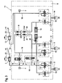
- FIG. 1 shows the hydraulic circuit diagram of an improved new motorcycle brake system in a schematic representation.
- the brake system consists of a hydraulically actuated front and rear brake circuit 4, 10, each with a connected to the front brake 4, by hand force proportionally actuated master cylinder 7 and a fußkraftproportional actuated master cylinder 13 on the rear brake 14th
- inlet and outlet valves 6, 12 are used, wherein in each case the open in the home position inlet valve 6 is inserted into the brake line 18 of the front or rear brake circuit 4, 10, which the associated Master cylinder 7, 13 with the front wheel or the rear wheel brake 5, 14 connects.
- the outlet valve 12 closed in the basic position is in each case inserted into a return line 15 of each brake circuit which connects the front or rear wheel brake 5, 14 with a respective low-pressure reservoir 16 and the suction side of a dual-circuit split pump 9, which operates on the return flow principle.
- the pump 9 therefore communicates with the brake lines 18 upstream of the inlet valves 6 via noise damping chambers 17 inserted in the two brake circuits, so that a demand-driven return of the brake fluid volume discharged from the front or rear wheel brake 5, 14 is ensured.
- the rear-wheel brake circuit 10 has, in addition to the illustrated features of the front-wheel brake circuit 4, an electromagnetically actuated separating valve 19 inserted between the master brake cylinder 13 and the intake valve 6 into the brake line 18, which is open in its basic position. Furthermore, between the separating valve 19 and the master cylinder 13 to the brake line 18 of the rear wheel 10, a leading via an electrical switching valve 20 suction path 21 connected to the pump 9, whereby the effective in the rear brake 10 pump portion at electrical excitation of the switching valve 20 pressure medium for autonomous pressure build-up in the Rear brake 14 can be seen from the master cylinder 13 and to promote the rear brake 14, while the isolation valve 19 remains to avoid a return promotion in the master cylinder 13 in its electrically energized locking position.
- upstream of the intake valve 6 is located on the brake pipe 18 of the front wheel brake circuit 4, a second pressure sensor 2 downstream of the inlet valve 6 connected to the rear wheel and a third pressure sensor upstream of the isolation valve 19, whereby the operation of the master cylinder 13 can be reliably detected.
- the brake pressure generated in the brake lines 18 can be limited at any time in the dual-circuit brake system.
- the detected by means of the first pressure sensor 1 in the front brake 4 master brake cylinder pressure forms the reference variable for electrically activating the rear wheel 10 effective pump 9, in cooperation with the inlet and outlet valves 6, 12, the separating and switching valve 19, 20 an electro-hydraulic brake pressure build-up in Rear wheel brake circuit 10 causes according to an electronic brake force distribution characteristic stored in the control unit 8, when only the master cylinder 7 connected to the front wheel brake circuit 4 is actuated.
- a logic circuit is provided in the electronic control unit 8 in which, depending on the evaluation result of the pressure sensor signals by means of the electrically actuable pump 9, an autonomous hydraulic pressure is generated in the rear wheel brake circuit 10.
- the symbolically illustrated control unit 8 forms an integral Component of a brake unit 11, which is preferably plugged for making electrical contact with the pressure sensors integrated in the brake unit 11 and the inlet and outlet valves 6, 11 integrated therein.
- the brake unit 11 can thus be attached to a motorcycle frame due to the particularly compact design in the vicinity of a battery.
- the rear wheel brake 14 is autonomously braked by a suitable pump control.
- the pump 9 removes this via the electrically open switching valve 20 pressure fluid from the master cylinder 13 and promotes it to the rear brake 14.
- the isolation valve 19 remains electrically operated in the closed position, which ensures that the pump pressure does not escape into the master cylinder 13.
- the pump 9 of the improved motorcycle brake after FIG. 1 Therefore, for each brake circuit, a valve circuit with different suction valves 24, 25, wherein the only manually acted upon brake circuit (front brake 4) arranged suction valve 25 has a much higher opening pressure (about 1.2 bar) than that in autonomously loadable brake circuit (rear wheel 10) arranged suction valve 24, the opening pressure is preferably about 0.2 bar. This ensures that at an autonomous and thus triggered via the pump 9 pressure build-up in not manually operated rear brake 10 at the same time a repercussion of the pump pressure on the front brake circuit 4 connected, manually operated master cylinder 7 is significantly reduced.
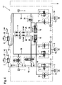
- FIG. 2 shows a modification of the circuit according to the invention according to FIG. 1 according to which the FIG. 1 known rear brake circuit arrangement with respect to the separating and switching valve 19, 20 as well as with respect to the pressure holding valve 28 has been transmitted to the front wheel brake 4. Accordingly, the two Pumpensaugventile 24, 25 are reversed in the two brake circuits.
- the pump suction valve 25 provided with the higher opening pressure is thus located in the rear wheel brake circuit 10, which reduces the feedback effect of the pump pressure on the foot-operated master cylinder 13 in the autonomous brake system operation.
- the pressure retention valve 28 is removed from the rear wheel brake circuit and arranged on the output side of the low-pressure accumulator 16 of the front wheel brake circuit 4, which helps that in the rear wheel brake 10 facilitates the secondary circuit ventilation.
- the low-pressure accumulator 16 is connected directly to a branch of the return line 15, while in the front-wheel brake 4 arranged low-pressure accumulator 16 is advantageously flushed through the return line 15 in the direction of the pressure-holding valve 28.
- FIG. 2 An autonomous operation of the motorcycle brake system FIG. 2 takes place accordingly via the (fußkraftproportionale) actuation of the rear brake cylinder 10 connected to the master cylinder 13, whereby the now known switching scheme (see Fig. 1 ) arranged in the front brake circuit 4 separating and switching valve 19, 20 occupy the non-illustrated, electromagnetically excited switching position in which the pump connected to the front wheel 4 pump circuit is connected to the intake side of the master cylinder 4, but the pressure side of the master cylinder 4 is disconnected, while connected to the rear wheel 10 Pump circuit due to the increased opening pressure of the suction valve 25, the pump reaction to the master cylinder 13 reduces. Moreover, since the master cylinder 13 in FIG. 2 is actuated by a brake pedal foot force proportional, a possibly pump reaction to the master cylinder 13 is hardly or not felt by the driver by the selected brake circuit distribution.
- FIG. 3 shows an extension of the circuit arrangement according to the invention FIG. 2 , which according to the embodiment of the invention FIG. 3 the front brake 5 has either two functionally separate brake calipers or a multi-piston brake, the brake piston are connected independently of each other via a two-part brake line 18 to the front wheel 4.
- autonomously adjustable front brake 4 in the direction of symbolically illustrated second front brake 5 is supplemented by a line branch, in the brake slip control upstream of the second front wheel brake 5, an inlet valve 6 and downstream of the second wheel brake 5 in a further return line 15, an outlet valve 12 of the type already cited are used.
- the line branch is branched off upstream of the separating and switching valve 19, 20 on the brake line 18 of the front wheel brake circuit 4, so that the symbolically illustrated second front brake 5 is not autonomously controllable, but only manually operated.
- This has the advantage that during an autonomous brake pressure control in the first front brake 5 a comfortable braking in the front brake circuit 4 is possible because in the symbolically illustrated second front brake 5, a brake pressure can be built up unhindered.
- one of the two front brakes 5 only manually via the master cylinder 7 can be actuated so that at any time a comfortable brake actuation feeling on the brake lever of the master cylinder 7 is perceptible.
- FIG. 3 corresponds to the structure of the rear wheel 10 in all essential elements of the representation of the rear wheel 10 after FIG. 2 ,
- the rear wheel brake 14 may be designed as a multi-piston brake, which are all connected via the brake line 18 of the rear wheel brake 10 on the second master cylinder 13.
- Fig. 1 prove the circuit arrangements Fig. 2 . 3 . 4 a pump 9, whose pump suction valve 24 arranged in the front-wheel brake circuit 4 has a substantially lower opening pressure (about 0.2 bar) than that arranged in the rear-wheel brake circuit 10 1.2 further), whereby a so-called idle pulsation of the pump 9 in the rear wheel 4 in the direction of the second master cylinder 7 is advantageously avoided, whereby the foot brake lever can be operated without feedback.
- Deviating from FIG. 1 is in the schematics after Fig. 2 to 4 the front wheel brake each autonomously controllable depending on the manual operation of the rear wheel, wherein for precise detection of each of the rear brake 14 and the front brake applied brake pressure, in particular for a brake slip control in both brake circuits, both the rear brake 14 and the front wheel Pressure sensor 2 is arranged.
- FIGS. 2 to 4 So far not all the others from the FIGS. 2 to 4 details have been received, they correspond functionally and structurally to the circuit diagram explained FIG. 1 , wherein all figures for identical elements have the same reference numerals.
- the pump suction valve 25 has a higher opening pressure than the pump suction valve 24 arranged in the rear-wheel brake circuit 10, which has the separating and switching valve 19, 20.
- FIG. 2 shows FIG. 2 an embodiment in which in the rear wheel brake 10, which does not have the separating and switching valve 19, 20, the pump suction valve 25 has a higher opening pressure than the pump suction valve 24 which is arranged in the front-wheel brake 4, which with the separating and switching valve 19, 20th is provided.
- FIG. 2 shows FIG. 3 in that on the brake circuit (front wheel brake circuit 4) which has the separating and switching valve 19, 20, upstream of the separating and switching valve 19, 20 to the brake circuit (front wheel brake circuit 4), a further wheel brake (front wheel brake 5) or a separately actuated brake piston is connected, which via the master brake cylinder 7 connected to the front brake circuit 4 (as a result of the volume of the additional wheel brake or brake piston) on the brake lever shown for a conventional brake operation desired brake lever feeling is guaranteed.
- the brake circuit front wheel brake circuit 4 which has the separating and switching valve 19, 20, upstream of the separating and switching valve 19, 20 to the brake circuit (front wheel brake circuit 4)
- a further wheel brake (front wheel brake 5) or a separately actuated brake piston is connected, which via the master brake cylinder 7 connected to the front brake circuit 4 (as a result of the volume of the additional wheel brake or brake piston) on the brake lever shown for a conventional brake operation desired brake lever feeling is guaranteed.
- FIG. 4 Finally, because of the arrangement of a pressure retention valve 28 at the output of the low pressure accumulator 16 is a useful measure for evacuation of the secondary circuit, to which upstream of the intake valve 6 to the brake line of the rear wheel brake an electromagnetically openable check valve 26 is connected downstream to the pressure retention valve 28 with the suction side of the pump 9 is connectable.
- the difference in the opening pressures of both pump suction valves 24, 25 between 0.5 to 1.5 bar, preferably 1 bar.
- the opening pressure of the pump suction valve 24, which is arranged in that brake circuit which has the separating and switching valve 19, 20, is between 0.1 to 0.4 bar, preferably 0.2 bar in order to achieve the highest possible delivery rate.
- Both pump suction valves 24, 25 are executed in the simplest embodiment as in the basic position closed by spring force check valves, preferably ball check valves, which are hydraulically aufschaltbar. Theoretically, an electromagnetic suction valve control would be conceivable.
- the pump 9 is in all embodiments as a piston pump executed, the pump piston are combined with the two pump suction valves 24, 25 in the block-shaped brake unit 11, in which the inlet and outlet valves 6, 12, the separating and switching valve 19, 20, the pressure sensors 1, 2, 3, and the two Low-pressure accumulator 16 are included.
- each of those low pressure accumulator 16 which is arranged in the brake circuit, which does not have the separating and switching valve 19, 20, no pressure retention valve 28 is required, what the secondary circuit ventilation and construction costs in this area favored.
Landscapes
- Engineering & Computer Science (AREA)
- Transportation (AREA)
- Mechanical Engineering (AREA)
- Physics & Mathematics (AREA)
- Fluid Mechanics (AREA)
- Regulating Braking Force (AREA)
- Hydraulic Control Valves For Brake Systems (AREA)
Claims (10)
- Système de freinage pour motocyclette, comprenant un circuit de freinage de roue avant (4) et de roue arrière (10) à commande hydraulique, avec deux cylindres de freinage principaux (7, 13) pour la commande indépendante des deux circuits de freinage (4, 10), avec une soupape d'entrée et une soupape de sortie (6, 12) prévues dans chaque circuit de freinage pour la régulation de la pression de freinage, avec une pompe (9) à deux circuits pour l'alimentation en pression du circuit de freinage de roue avant et de roue arrière (4, 10), qui fonctionne selon le principe de refoulement, avec une soupape d'aspiration de pompe (24, 25) et une soupape de pression de pompe dans chaque circuit de pompe, avec un accumulateur basse pression (16) raccordé en amont de la soupape d'aspiration de pompe (24, 25) de chaque côté d'aspiration de la pompe, avec un premier frein de roue (5) dans un premier circuit de freinage (4) des circuits susmentionnés de freinage de roue avant et de roue arrière, et un deuxième frein de roue (14) dans un deuxième circuit de freinage (10) des circuits susmentionnés de freinage de roue avant et de roue arrière, ainsi qu'avec une soupape de coupure (19) et d'inversion (20) dans chaque circuit de freinage (10, 4), qui peuvent être sollicitées par la pression de refoulement de la pompe (9) pour augmenter de manière autonome la pression de freinage dans l'un des deux freins de roue (14, 5) indépendamment d'un actionnement du cylindre de freinage principal (13, 7) qui lui est associé, caractérisé en ce que dans le circuit de freinage qui ne présente pas la soupape de coupure et d'inversion (19, 20), la soupape d'aspiration de pompe (25) présente une pression d'ouverture plus élevée que la soupape d'aspiration de pompe (24) qui est disposée dans le circuit de freinage qui présente la soupape de coupure et d'inversion (19, 20).
- Système de freinage pour motocyclette selon la revendication 1, caractérisé en ce que dans le circuit de freinage de roue avant (4), qui ne présente pas la soupape de coupure et d'inversion (19, 20), la soupape d'aspiration de pompe (25) présente une plus grande pression d'ouverture que la soupape d'aspiration de pompe (24) qui est disposée dans le circuit de freinage de roue arrière (10), qui présente la soupape de coupure et d'inversion (19, 20).
- Système de freinage pour motocyclette selon la revendication 1, caractérisé en ce que dans le circuit de freinage de roue arrière (10) qui ne présente pas la soupape de coupure et d'inversion (19, 20), la soupape d'aspiration de pompe (25) présente une plus grande pression d'ouverture que la soupape d'aspiration de pompe (24) qui est disposée dans le circuit de freinage de roue avant (4) qui présente la soupape de coupure et d'inversion (19, 20).
- Système de freinage pour motocyclette selon l'une quelconque des revendications précédentes, caractérisé en ce que la différence des pressions d'ouverture des deux soupapes d'aspiration de pompe (24, 25) est comprise entre 0,5 à 1,5 bar, de préférence est de 1 bar.
- Système de freinage pour motocyclette selon l'une quelconque des revendications précédentes, caractérisé en ce que la pression d'ouverture de la soupape d'aspiration de pompe (24) qui est disposée dans le circuit de freinage qui présente la soupape de coupure et d'inversion (19, 20), est comprise entre 0,1 et 0,4 bar, de préférence vaut 0,2 bar.
- Système de freinage pour motocyclette selon l'une quelconque des revendications précédentes, caractérisé en ce que la pression d'ouverture de la soupape d'aspiration de pompe (25) qui est disposée dans le circuit de freinage qui ne présente pas la soupape de coupure et d'inversion (19, 20), est comprise entre 0,6 et 1,6 bar, de préférence vaut 1,2 bar.
- Système de freinage pour motocyclette selon la revendication 6, caractérisé en ce que les deux soupapes d'aspiration de pompe (24, 25) sont réalisées sous forme de soupapes de non retour fermées en position de base par la force d'un ressort, de préférence des soupapes de non retour à bille, qui peuvent être commutées hydrauliquement.
- Système de freinage pour motocyclette selon l'une quelconque des revendications précédentes, caractérisé en ce que la pompe (9) est réalisée sous forme d'une pompe à piston à double flux, dont les pistons de pompe sont réunis aux deux soupapes d'aspiration de pompe (24, 25) dans une unité de freinage en forme de bloc (11), dans laquelle sont reçus plusieurs soupapes d'entrée et de sortie (6, 12), la soupape de coupure et d'inversion (19, 20), plusieurs capteurs de pression (1, 2, 3) ainsi que les deux accumulateurs de basse pression.
- Système de freinage pour motocyclette selon l'une quelconque des revendications précédentes, caractérisé en ce qu'au niveau du circuit de freinage qui présente la soupape de coupure et d'inversion (19, 20), en aval de la soupape de coupure et d'inversion (19, 20), un autre frein de roue (5) est raccordé au circuit de freinage, lequel peut être directement commandé par le biais du cylindre de freinage principal (7) raccordé au circuit de freinage.
- Système de freinage pour motocyclette selon la revendication 9, caractérisé en ce que la pression de freinage dans l'autre frein de roue (5) peut être régulée par le biais d'autres soupapes d'entrée et de sortie (6, 12).
Applications Claiming Priority (3)
| Application Number | Priority Date | Filing Date | Title |
|---|---|---|---|
| DE102006023341 | 2006-05-17 | ||
| DE102006045038A DE102006045038A1 (de) | 2006-05-17 | 2006-09-23 | Kraftradbremsanlage |
| PCT/EP2007/054586 WO2007131960A1 (fr) | 2006-05-17 | 2007-05-11 | Système de freinage pour motocycle |
Publications (2)
| Publication Number | Publication Date |
|---|---|
| EP2019766A1 EP2019766A1 (fr) | 2009-02-04 |
| EP2019766B1 true EP2019766B1 (fr) | 2009-08-26 |
Family
ID=38330179
Family Applications (1)
| Application Number | Title | Priority Date | Filing Date |
|---|---|---|---|
| EP07729038A Active EP2019766B1 (fr) | 2006-05-17 | 2007-05-11 | Système de freinage pour motocycle |
Country Status (5)
| Country | Link |
|---|---|
| US (1) | US8480184B2 (fr) |
| EP (1) | EP2019766B1 (fr) |
| JP (1) | JP5259577B2 (fr) |
| DE (2) | DE102006045038A1 (fr) |
| WO (1) | WO2007131960A1 (fr) |
Families Citing this family (3)
| Publication number | Priority date | Publication date | Assignee | Title |
|---|---|---|---|---|
| DE102011076640A1 (de) * | 2010-09-14 | 2012-03-15 | Robert Bosch Gmbh | Verfahren zur Bremsmomentenregelung in einem Zweiradfahrzeug bei Schräglagenfahrt |
| DE102014222573A1 (de) * | 2014-11-05 | 2016-05-12 | Robert Bosch Gmbh | Hydraulikeinrichtung einer Fahrzeugbremsanlage |
| TWI645996B (zh) * | 2017-09-15 | 2019-01-01 | 六和機械股份有限公司 | 具防止前傾翻覆功能的煞車系統 |
Family Cites Families (11)
| Publication number | Priority date | Publication date | Assignee | Title |
|---|---|---|---|---|
| DE4108756A1 (de) * | 1990-10-05 | 1992-09-24 | Teves Gmbh Alfred | Kraftfahrzeugbremsanlage mit schlupfabhaengiger regelung des bremsdruckes |
| JPH05201320A (ja) * | 1992-01-29 | 1993-08-10 | Toyota Motor Corp | 還流式アンチスキッド型液圧ブレーキ装置 |
| JPH0811694A (ja) * | 1994-06-28 | 1996-01-16 | Nisshinbo Ind Inc | 車両用ブレーキ制御装置 |
| JPH08230644A (ja) * | 1994-12-28 | 1996-09-10 | Nippondenso Co Ltd | ブレーキ液圧制御装置 |
| JPH1059156A (ja) * | 1996-08-20 | 1998-03-03 | Suzuki Motor Corp | ブレーキシステム |
| JP3851066B2 (ja) * | 2000-07-19 | 2006-11-29 | トヨタ自動車株式会社 | ブレーキ装置 |
| JP2002264787A (ja) | 2001-03-07 | 2002-09-18 | Bosch Braking Systems Co Ltd | 電気式ブレーキ制御装置 |
| DE60229185D1 (de) * | 2001-07-19 | 2008-11-20 | Bayerische Motoren Werke Ag | Bremssteuerverfahren und Vorrichtung für Motorräder |
| DE102005003774A1 (de) * | 2004-10-07 | 2006-05-24 | Continental Teves Ag & Co. Ohg | Kraftradbremsanlage |
| DE102005005390A1 (de) * | 2004-10-13 | 2006-05-24 | Continental Teves Ag & Co. Ohg | Kraftradbremsanlage |
| DE102004051119A1 (de) * | 2004-10-20 | 2006-04-27 | Bayerische Motoren Werke Ag | Integralbremse für ein Motorrad |
-
2006
- 2006-09-23 DE DE102006045038A patent/DE102006045038A1/de not_active Withdrawn
-
2007
- 2007-05-11 US US12/301,114 patent/US8480184B2/en active Active
- 2007-05-11 DE DE502007001417T patent/DE502007001417D1/de active Active
- 2007-05-11 JP JP2009510425A patent/JP5259577B2/ja active Active
- 2007-05-11 WO PCT/EP2007/054586 patent/WO2007131960A1/fr active Application Filing
- 2007-05-11 EP EP07729038A patent/EP2019766B1/fr active Active
Also Published As
| Publication number | Publication date |
|---|---|
| WO2007131960A1 (fr) | 2007-11-22 |
| EP2019766A1 (fr) | 2009-02-04 |
| JP5259577B2 (ja) | 2013-08-07 |
| DE502007001417D1 (de) | 2009-10-08 |
| US8480184B2 (en) | 2013-07-09 |
| DE102006045038A1 (de) | 2007-11-22 |
| JP2009537369A (ja) | 2009-10-29 |
| US20090184567A1 (en) | 2009-07-23 |
Similar Documents
| Publication | Publication Date | Title |
|---|---|---|
| WO2012143313A1 (fr) | Système de freinage pour véhicules automobiles et procédé permettant de faire fonctionner un système de freinage | |
| DE102013206324A1 (de) | Bremssystem für ein Fahrzeug und Verfahren zum Betreiben des Bremssystems | |
| EP1799521B1 (fr) | Systeme de freinage de motocyclette | |
| DE4102496A1 (de) | Bremsdruck-steuereinrichtung | |
| DE60214663T2 (de) | Elektronisch gesteuertes Kraftfahrzeug-Bremssystem | |
| WO2005075269A1 (fr) | Systeme de freinage de motocyclette | |
| DE19626289B4 (de) | Hydraulische Bremsanlage mit einer Rückförderpumpe | |
| DE102008060622A1 (de) | Kraftradbremsanlage | |
| EP2268516B1 (fr) | Générateur de pression d un dispositif de freinage hydraulique de véhicule et procédé de fonctionnement associé | |
| EP1993889B1 (fr) | Système de freinage de motocyclette | |
| EP2019766B1 (fr) | Système de freinage pour motocycle | |
| EP1963153B1 (fr) | Systeme de freinage d'un motocycle | |
| DE102005027856B4 (de) | Kraftfahrzeugbremsanlage | |
| DE10324243A1 (de) | Verfahren und Vorrichtung zum Abbremsen eines Kraftfahrzeugs mittels eines Fahrerassistenzsystems | |
| DE102004027508A1 (de) | Hydraulische Bremsanlage und Verfahren zur Beeinflussung einer hydraulischen Bremsanlage | |
| DE102006036501A1 (de) | Kraftradbremsanlage | |
| DE102004014171A1 (de) | Fahrzeugbremssystem und Verfahren zum Betreiben des Fahrzeugbremssystems | |
| DE102006033335A1 (de) | Kraftradbremsanlage | |
| DE10065234A1 (de) | Elektrohydraulische Fahrzeugbremsanlage | |
| DE4122643C2 (de) | Hydraulische Bremsanlage mit einer Blockierschutz- und Antriebsschlupfregeleinrichtung für Kraftfahrzeuge | |
| DE102010001532A1 (de) | Kraftradbremsanlage | |
| DE102012214586A1 (de) | Kraftradbremsanlage | |
| WO2011116998A1 (fr) | Dispositif et procédé pour commander un système de freinage | |
| DE102006042465A1 (de) | Kraftradbremsanlage | |
| DE102010039783A1 (de) | Bremsanlage |
Legal Events
| Date | Code | Title | Description |
|---|---|---|---|
| PUAI | Public reference made under article 153(3) epc to a published international application that has entered the european phase |
Free format text: ORIGINAL CODE: 0009012 |
|
| 17P | Request for examination filed |
Effective date: 20081217 |
|
| AK | Designated contracting states |
Kind code of ref document: A1 Designated state(s): AT BE BG CH CY CZ DE DK EE ES FI FR GB GR HU IE IS IT LI LT LU LV MC MT NL PL PT RO SE SI SK TR |
|
| AX | Request for extension of the european patent |
Extension state: AL BA HR MK RS |
|
| GRAP | Despatch of communication of intention to grant a patent |
Free format text: ORIGINAL CODE: EPIDOSNIGR1 |
|
| DAX | Request for extension of the european patent (deleted) | ||
| RBV | Designated contracting states (corrected) |
Designated state(s): DE |
|
| GRAS | Grant fee paid |
Free format text: ORIGINAL CODE: EPIDOSNIGR3 |
|
| GRAA | (expected) grant |
Free format text: ORIGINAL CODE: 0009210 |
|
| AK | Designated contracting states |
Kind code of ref document: B1 Designated state(s): DE |
|
| REF | Corresponds to: |
Ref document number: 502007001417 Country of ref document: DE Date of ref document: 20091008 Kind code of ref document: P |
|
| PLBE | No opposition filed within time limit |
Free format text: ORIGINAL CODE: 0009261 |
|
| STAA | Information on the status of an ep patent application or granted ep patent |
Free format text: STATUS: NO OPPOSITION FILED WITHIN TIME LIMIT |
|
| 26N | No opposition filed |
Effective date: 20100527 |
|
| REG | Reference to a national code |
Ref country code: DE Ref legal event code: R084 Ref document number: 502007001417 Country of ref document: DE |
|
| REG | Reference to a national code |
Ref country code: DE Ref legal event code: R081 Ref document number: 502007001417 Country of ref document: DE Owner name: CONTINENTAL AUTOMOTIVE TECHNOLOGIES GMBH, DE Free format text: FORMER OWNER: CONTINENTAL TEVES AG & CO. OHG, 60488 FRANKFURT, DE |
|
| P01 | Opt-out of the competence of the unified patent court (upc) registered |
Effective date: 20230522 |
|
| PGFP | Annual fee paid to national office [announced via postgrant information from national office to epo] |
Ref country code: DE Payment date: 20230531 Year of fee payment: 17 |
|
| REG | Reference to a national code |
Ref country code: DE Ref legal event code: R081 Ref document number: 502007001417 Country of ref document: DE Owner name: CONTINENTAL AUTOMOTIVE TECHNOLOGIES GMBH, DE Free format text: FORMER OWNER: CONTINENTAL AUTOMOTIVE TECHNOLOGIES GMBH, 30165 HANNOVER, DE |