EP2019766B1 - Motorcycle braking system - Google Patents
Motorcycle braking system Download PDFInfo
- Publication number
- EP2019766B1 EP2019766B1 EP07729038A EP07729038A EP2019766B1 EP 2019766 B1 EP2019766 B1 EP 2019766B1 EP 07729038 A EP07729038 A EP 07729038A EP 07729038 A EP07729038 A EP 07729038A EP 2019766 B1 EP2019766 B1 EP 2019766B1
- Authority
- EP
- European Patent Office
- Prior art keywords
- brake
- valve
- pump
- circuit
- pressure
- Prior art date
- Legal status (The legal status is an assumption and is not a legal conclusion. Google has not performed a legal analysis and makes no representation as to the accuracy of the status listed.)
- Active
Links
- 238000011144 upstream manufacturing Methods 0.000 claims description 9
- 230000001105 regulatory effect Effects 0.000 claims description 2
- 238000010586 diagram Methods 0.000 description 6
- 230000014759 maintenance of location Effects 0.000 description 5
- 238000002955 isolation Methods 0.000 description 3
- 230000000903 blocking effect Effects 0.000 description 2
- 238000001514 detection method Methods 0.000 description 2
- 230000000694 effects Effects 0.000 description 2
- 238000011156 evaluation Methods 0.000 description 2
- 239000012530 fluid Substances 0.000 description 2
- 230000010355 oscillation Effects 0.000 description 2
- 230000010349 pulsation Effects 0.000 description 2
- 238000009423 ventilation Methods 0.000 description 2
- 240000003517 Elaeocarpus dentatus Species 0.000 description 1
- 230000001133 acceleration Effects 0.000 description 1
- 230000003213 activating effect Effects 0.000 description 1
- 238000010276 construction Methods 0.000 description 1
- 238000013016 damping Methods 0.000 description 1
- 230000005284 excitation Effects 0.000 description 1
- 230000004048 modification Effects 0.000 description 1
- 238000012986 modification Methods 0.000 description 1
- 230000001960 triggered effect Effects 0.000 description 1
Images


Classifications
-
- B—PERFORMING OPERATIONS; TRANSPORTING
- B60—VEHICLES IN GENERAL
- B60T—VEHICLE BRAKE CONTROL SYSTEMS OR PARTS THEREOF; BRAKE CONTROL SYSTEMS OR PARTS THEREOF, IN GENERAL; ARRANGEMENT OF BRAKING ELEMENTS ON VEHICLES IN GENERAL; PORTABLE DEVICES FOR PREVENTING UNWANTED MOVEMENT OF VEHICLES; VEHICLE MODIFICATIONS TO FACILITATE COOLING OF BRAKES
- B60T8/00—Arrangements for adjusting wheel-braking force to meet varying vehicular or ground-surface conditions, e.g. limiting or varying distribution of braking force
- B60T8/32—Arrangements for adjusting wheel-braking force to meet varying vehicular or ground-surface conditions, e.g. limiting or varying distribution of braking force responsive to a speed condition, e.g. acceleration or deceleration
- B60T8/321—Arrangements for adjusting wheel-braking force to meet varying vehicular or ground-surface conditions, e.g. limiting or varying distribution of braking force responsive to a speed condition, e.g. acceleration or deceleration deceleration
- B60T8/3225—Systems specially adapted for single-track vehicles, e.g. motorcycles
-
- B—PERFORMING OPERATIONS; TRANSPORTING
- B60—VEHICLES IN GENERAL
- B60T—VEHICLE BRAKE CONTROL SYSTEMS OR PARTS THEREOF; BRAKE CONTROL SYSTEMS OR PARTS THEREOF, IN GENERAL; ARRANGEMENT OF BRAKING ELEMENTS ON VEHICLES IN GENERAL; PORTABLE DEVICES FOR PREVENTING UNWANTED MOVEMENT OF VEHICLES; VEHICLE MODIFICATIONS TO FACILITATE COOLING OF BRAKES
- B60T8/00—Arrangements for adjusting wheel-braking force to meet varying vehicular or ground-surface conditions, e.g. limiting or varying distribution of braking force
- B60T8/26—Arrangements for adjusting wheel-braking force to meet varying vehicular or ground-surface conditions, e.g. limiting or varying distribution of braking force characterised by producing differential braking between front and rear wheels
- B60T8/261—Arrangements for adjusting wheel-braking force to meet varying vehicular or ground-surface conditions, e.g. limiting or varying distribution of braking force characterised by producing differential braking between front and rear wheels specially adapted for use in motorcycles
-
- B—PERFORMING OPERATIONS; TRANSPORTING
- B60—VEHICLES IN GENERAL
- B60T—VEHICLE BRAKE CONTROL SYSTEMS OR PARTS THEREOF; BRAKE CONTROL SYSTEMS OR PARTS THEREOF, IN GENERAL; ARRANGEMENT OF BRAKING ELEMENTS ON VEHICLES IN GENERAL; PORTABLE DEVICES FOR PREVENTING UNWANTED MOVEMENT OF VEHICLES; VEHICLE MODIFICATIONS TO FACILITATE COOLING OF BRAKES
- B60T8/00—Arrangements for adjusting wheel-braking force to meet varying vehicular or ground-surface conditions, e.g. limiting or varying distribution of braking force
- B60T8/32—Arrangements for adjusting wheel-braking force to meet varying vehicular or ground-surface conditions, e.g. limiting or varying distribution of braking force responsive to a speed condition, e.g. acceleration or deceleration
- B60T8/34—Arrangements for adjusting wheel-braking force to meet varying vehicular or ground-surface conditions, e.g. limiting or varying distribution of braking force responsive to a speed condition, e.g. acceleration or deceleration having a fluid pressure regulator responsive to a speed condition
- B60T8/40—Arrangements for adjusting wheel-braking force to meet varying vehicular or ground-surface conditions, e.g. limiting or varying distribution of braking force responsive to a speed condition, e.g. acceleration or deceleration having a fluid pressure regulator responsive to a speed condition comprising an additional fluid circuit including fluid pressurising means for modifying the pressure of the braking fluid, e.g. including wheel driven pumps for detecting a speed condition, or pumps which are controlled by means independent of the braking system
- B60T8/4072—Systems in which a driver input signal is used as a control signal for the additional fluid circuit which is normally used for braking
-
- B—PERFORMING OPERATIONS; TRANSPORTING
- B60—VEHICLES IN GENERAL
- B60T—VEHICLE BRAKE CONTROL SYSTEMS OR PARTS THEREOF; BRAKE CONTROL SYSTEMS OR PARTS THEREOF, IN GENERAL; ARRANGEMENT OF BRAKING ELEMENTS ON VEHICLES IN GENERAL; PORTABLE DEVICES FOR PREVENTING UNWANTED MOVEMENT OF VEHICLES; VEHICLE MODIFICATIONS TO FACILITATE COOLING OF BRAKES
- B60T8/00—Arrangements for adjusting wheel-braking force to meet varying vehicular or ground-surface conditions, e.g. limiting or varying distribution of braking force
- B60T8/32—Arrangements for adjusting wheel-braking force to meet varying vehicular or ground-surface conditions, e.g. limiting or varying distribution of braking force responsive to a speed condition, e.g. acceleration or deceleration
- B60T8/34—Arrangements for adjusting wheel-braking force to meet varying vehicular or ground-surface conditions, e.g. limiting or varying distribution of braking force responsive to a speed condition, e.g. acceleration or deceleration having a fluid pressure regulator responsive to a speed condition
- B60T8/42—Arrangements for adjusting wheel-braking force to meet varying vehicular or ground-surface conditions, e.g. limiting or varying distribution of braking force responsive to a speed condition, e.g. acceleration or deceleration having a fluid pressure regulator responsive to a speed condition having expanding chambers for controlling pressure, i.e. closed systems
- B60T8/4275—Pump-back systems
- B60T8/4291—Pump-back systems having means to reduce or eliminate pedal kick-back
Definitions
- the invention relates to a motorcycle brake system according to the preamble of patent claim 1.
- the brake system has a hydraulically actuated front and rear brake circuit, wherein each brake circuit is connected either to a foot or manually operated master cylinder.
- electromagnetically activated intake and exhaust valves are used in the front and rear wheel brake circuits, as well as with a pump to build up pressure in the two brake circuits.
- the rear wheel brake circuit has an additional valve arrangement which, with manual actuation of the front wheel brake circuit, simultaneously enables pressure buildup on the rear wheel brake via the pump without the necessity of actuating the main brake cylinder of the rear wheel brake circuit.
- a first pressure sensor is arranged to detect the manual operation of the front wheel brake circuit and to activate the pump to build up an autonomous brake pressure in the rear wheel brake can.
- the pump can be electrically activated and a regulated brake pressure in the rear brake can be established.
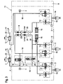
- FIG. 1 shows the hydraulic circuit diagram of an improved new motorcycle brake system in a schematic representation.
- the brake system consists of a hydraulically actuated front and rear brake circuit 4, 10, each with a connected to the front brake 4, by hand force proportionally actuated master cylinder 7 and a fußkraftproportional actuated master cylinder 13 on the rear brake 14th
- inlet and outlet valves 6, 12 are used, wherein in each case the open in the home position inlet valve 6 is inserted into the brake line 18 of the front or rear brake circuit 4, 10, which the associated Master cylinder 7, 13 with the front wheel or the rear wheel brake 5, 14 connects.
- the outlet valve 12 closed in the basic position is in each case inserted into a return line 15 of each brake circuit which connects the front or rear wheel brake 5, 14 with a respective low-pressure reservoir 16 and the suction side of a dual-circuit split pump 9, which operates on the return flow principle.
- the pump 9 therefore communicates with the brake lines 18 upstream of the inlet valves 6 via noise damping chambers 17 inserted in the two brake circuits, so that a demand-driven return of the brake fluid volume discharged from the front or rear wheel brake 5, 14 is ensured.
- the rear-wheel brake circuit 10 has, in addition to the illustrated features of the front-wheel brake circuit 4, an electromagnetically actuated separating valve 19 inserted between the master brake cylinder 13 and the intake valve 6 into the brake line 18, which is open in its basic position. Furthermore, between the separating valve 19 and the master cylinder 13 to the brake line 18 of the rear wheel 10, a leading via an electrical switching valve 20 suction path 21 connected to the pump 9, whereby the effective in the rear brake 10 pump portion at electrical excitation of the switching valve 20 pressure medium for autonomous pressure build-up in the Rear brake 14 can be seen from the master cylinder 13 and to promote the rear brake 14, while the isolation valve 19 remains to avoid a return promotion in the master cylinder 13 in its electrically energized locking position.
- upstream of the intake valve 6 is located on the brake pipe 18 of the front wheel brake circuit 4, a second pressure sensor 2 downstream of the inlet valve 6 connected to the rear wheel and a third pressure sensor upstream of the isolation valve 19, whereby the operation of the master cylinder 13 can be reliably detected.
- the brake pressure generated in the brake lines 18 can be limited at any time in the dual-circuit brake system.
- the detected by means of the first pressure sensor 1 in the front brake 4 master brake cylinder pressure forms the reference variable for electrically activating the rear wheel 10 effective pump 9, in cooperation with the inlet and outlet valves 6, 12, the separating and switching valve 19, 20 an electro-hydraulic brake pressure build-up in Rear wheel brake circuit 10 causes according to an electronic brake force distribution characteristic stored in the control unit 8, when only the master cylinder 7 connected to the front wheel brake circuit 4 is actuated.
- a logic circuit is provided in the electronic control unit 8 in which, depending on the evaluation result of the pressure sensor signals by means of the electrically actuable pump 9, an autonomous hydraulic pressure is generated in the rear wheel brake circuit 10.
- the symbolically illustrated control unit 8 forms an integral Component of a brake unit 11, which is preferably plugged for making electrical contact with the pressure sensors integrated in the brake unit 11 and the inlet and outlet valves 6, 11 integrated therein.
- the brake unit 11 can thus be attached to a motorcycle frame due to the particularly compact design in the vicinity of a battery.
- the rear wheel brake 14 is autonomously braked by a suitable pump control.
- the pump 9 removes this via the electrically open switching valve 20 pressure fluid from the master cylinder 13 and promotes it to the rear brake 14.
- the isolation valve 19 remains electrically operated in the closed position, which ensures that the pump pressure does not escape into the master cylinder 13.
- the pump 9 of the improved motorcycle brake after FIG. 1 Therefore, for each brake circuit, a valve circuit with different suction valves 24, 25, wherein the only manually acted upon brake circuit (front brake 4) arranged suction valve 25 has a much higher opening pressure (about 1.2 bar) than that in autonomously loadable brake circuit (rear wheel 10) arranged suction valve 24, the opening pressure is preferably about 0.2 bar. This ensures that at an autonomous and thus triggered via the pump 9 pressure build-up in not manually operated rear brake 10 at the same time a repercussion of the pump pressure on the front brake circuit 4 connected, manually operated master cylinder 7 is significantly reduced.
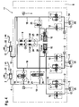
- FIG. 2 shows a modification of the circuit according to the invention according to FIG. 1 according to which the FIG. 1 known rear brake circuit arrangement with respect to the separating and switching valve 19, 20 as well as with respect to the pressure holding valve 28 has been transmitted to the front wheel brake 4. Accordingly, the two Pumpensaugventile 24, 25 are reversed in the two brake circuits.
- the pump suction valve 25 provided with the higher opening pressure is thus located in the rear wheel brake circuit 10, which reduces the feedback effect of the pump pressure on the foot-operated master cylinder 13 in the autonomous brake system operation.
- the pressure retention valve 28 is removed from the rear wheel brake circuit and arranged on the output side of the low-pressure accumulator 16 of the front wheel brake circuit 4, which helps that in the rear wheel brake 10 facilitates the secondary circuit ventilation.
- the low-pressure accumulator 16 is connected directly to a branch of the return line 15, while in the front-wheel brake 4 arranged low-pressure accumulator 16 is advantageously flushed through the return line 15 in the direction of the pressure-holding valve 28.
- FIG. 2 An autonomous operation of the motorcycle brake system FIG. 2 takes place accordingly via the (fußkraftproportionale) actuation of the rear brake cylinder 10 connected to the master cylinder 13, whereby the now known switching scheme (see Fig. 1 ) arranged in the front brake circuit 4 separating and switching valve 19, 20 occupy the non-illustrated, electromagnetically excited switching position in which the pump connected to the front wheel 4 pump circuit is connected to the intake side of the master cylinder 4, but the pressure side of the master cylinder 4 is disconnected, while connected to the rear wheel 10 Pump circuit due to the increased opening pressure of the suction valve 25, the pump reaction to the master cylinder 13 reduces. Moreover, since the master cylinder 13 in FIG. 2 is actuated by a brake pedal foot force proportional, a possibly pump reaction to the master cylinder 13 is hardly or not felt by the driver by the selected brake circuit distribution.
- FIG. 3 shows an extension of the circuit arrangement according to the invention FIG. 2 , which according to the embodiment of the invention FIG. 3 the front brake 5 has either two functionally separate brake calipers or a multi-piston brake, the brake piston are connected independently of each other via a two-part brake line 18 to the front wheel 4.
- autonomously adjustable front brake 4 in the direction of symbolically illustrated second front brake 5 is supplemented by a line branch, in the brake slip control upstream of the second front wheel brake 5, an inlet valve 6 and downstream of the second wheel brake 5 in a further return line 15, an outlet valve 12 of the type already cited are used.
- the line branch is branched off upstream of the separating and switching valve 19, 20 on the brake line 18 of the front wheel brake circuit 4, so that the symbolically illustrated second front brake 5 is not autonomously controllable, but only manually operated.
- This has the advantage that during an autonomous brake pressure control in the first front brake 5 a comfortable braking in the front brake circuit 4 is possible because in the symbolically illustrated second front brake 5, a brake pressure can be built up unhindered.
- one of the two front brakes 5 only manually via the master cylinder 7 can be actuated so that at any time a comfortable brake actuation feeling on the brake lever of the master cylinder 7 is perceptible.
- FIG. 3 corresponds to the structure of the rear wheel 10 in all essential elements of the representation of the rear wheel 10 after FIG. 2 ,
- the rear wheel brake 14 may be designed as a multi-piston brake, which are all connected via the brake line 18 of the rear wheel brake 10 on the second master cylinder 13.
- Fig. 1 prove the circuit arrangements Fig. 2 . 3 . 4 a pump 9, whose pump suction valve 24 arranged in the front-wheel brake circuit 4 has a substantially lower opening pressure (about 0.2 bar) than that arranged in the rear-wheel brake circuit 10 1.2 further), whereby a so-called idle pulsation of the pump 9 in the rear wheel 4 in the direction of the second master cylinder 7 is advantageously avoided, whereby the foot brake lever can be operated without feedback.
- Deviating from FIG. 1 is in the schematics after Fig. 2 to 4 the front wheel brake each autonomously controllable depending on the manual operation of the rear wheel, wherein for precise detection of each of the rear brake 14 and the front brake applied brake pressure, in particular for a brake slip control in both brake circuits, both the rear brake 14 and the front wheel Pressure sensor 2 is arranged.
- FIGS. 2 to 4 So far not all the others from the FIGS. 2 to 4 details have been received, they correspond functionally and structurally to the circuit diagram explained FIG. 1 , wherein all figures for identical elements have the same reference numerals.
- the pump suction valve 25 has a higher opening pressure than the pump suction valve 24 arranged in the rear-wheel brake circuit 10, which has the separating and switching valve 19, 20.
- FIG. 2 shows FIG. 2 an embodiment in which in the rear wheel brake 10, which does not have the separating and switching valve 19, 20, the pump suction valve 25 has a higher opening pressure than the pump suction valve 24 which is arranged in the front-wheel brake 4, which with the separating and switching valve 19, 20th is provided.
- FIG. 2 shows FIG. 3 in that on the brake circuit (front wheel brake circuit 4) which has the separating and switching valve 19, 20, upstream of the separating and switching valve 19, 20 to the brake circuit (front wheel brake circuit 4), a further wheel brake (front wheel brake 5) or a separately actuated brake piston is connected, which via the master brake cylinder 7 connected to the front brake circuit 4 (as a result of the volume of the additional wheel brake or brake piston) on the brake lever shown for a conventional brake operation desired brake lever feeling is guaranteed.
- the brake circuit front wheel brake circuit 4 which has the separating and switching valve 19, 20, upstream of the separating and switching valve 19, 20 to the brake circuit (front wheel brake circuit 4)
- a further wheel brake (front wheel brake 5) or a separately actuated brake piston is connected, which via the master brake cylinder 7 connected to the front brake circuit 4 (as a result of the volume of the additional wheel brake or brake piston) on the brake lever shown for a conventional brake operation desired brake lever feeling is guaranteed.
- FIG. 4 Finally, because of the arrangement of a pressure retention valve 28 at the output of the low pressure accumulator 16 is a useful measure for evacuation of the secondary circuit, to which upstream of the intake valve 6 to the brake line of the rear wheel brake an electromagnetically openable check valve 26 is connected downstream to the pressure retention valve 28 with the suction side of the pump 9 is connectable.
- the difference in the opening pressures of both pump suction valves 24, 25 between 0.5 to 1.5 bar, preferably 1 bar.
- the opening pressure of the pump suction valve 24, which is arranged in that brake circuit which has the separating and switching valve 19, 20, is between 0.1 to 0.4 bar, preferably 0.2 bar in order to achieve the highest possible delivery rate.
- Both pump suction valves 24, 25 are executed in the simplest embodiment as in the basic position closed by spring force check valves, preferably ball check valves, which are hydraulically aufschaltbar. Theoretically, an electromagnetic suction valve control would be conceivable.
- the pump 9 is in all embodiments as a piston pump executed, the pump piston are combined with the two pump suction valves 24, 25 in the block-shaped brake unit 11, in which the inlet and outlet valves 6, 12, the separating and switching valve 19, 20, the pressure sensors 1, 2, 3, and the two Low-pressure accumulator 16 are included.
- each of those low pressure accumulator 16 which is arranged in the brake circuit, which does not have the separating and switching valve 19, 20, no pressure retention valve 28 is required, what the secondary circuit ventilation and construction costs in this area favored.
Description
Die Erfindung betrifft eine Kraftradbremsanlage nach dem Oberbegriff des Patentanspruchs 1.The invention relates to a motorcycle brake system according to the preamble of
Aus der
Am Vorderradbremskreis ist ein erster Drucksensor angeordnet, um die manuelle Betätigung des Vorderradbremskreises zu erfassen und die Pumpe zum Aufbau eines autonomen Bremsdruck im Hinterradbremskreis aktivieren zu können.At the front wheel brake circuit, a first pressure sensor is arranged to detect the manual operation of the front wheel brake circuit and to activate the pump to build up an autonomous brake pressure in the rear wheel brake can.
Abhängig vom sicheren Erkennen des Hauptbremszylinderdrucks im Vorderradbremskreis kann sodann die Pumpe elektrisch aktiviert und ein geregelter Bremsdruck in der Hinterradbremse aufgebaut werden.Depending on the safe detection of the master cylinder pressure in the front brake circuit then the pump can be electrically activated and a regulated brake pressure in the rear brake can be established.
Mit dem Anlauf der Pumpe stellt sich jedoch das Problem, dass Druckschwingungen initiiert werden, die auf den manuell betätigten Hauptbremszylinder zurückwirken und im Handbremshebel unangenehm spürbar sind.With the start of the pump, however, there is the problem that pressure oscillations are initiated, which act back on the manually operated master cylinder and are uncomfortable in the handbrake lever.
Daher ist es die Aufgabe der vorliegenden Erfindung, eine Kraftradbremsanlage der bekannten Art derart zu verbessern, dass die beim Anlauf der Pumpe initiierten Druckschwingungen nicht oder nur gering auf den manuell betätigten Hauptbremszylinder zurückwirken können.Therefore, it is the object of the present invention to improve a motorcycle brake system of the known type such that the initiated during the start of the pump pressure oscillations can not react or only slightly on the manually operated master cylinder.
Diese Aufgabe wird für eine Kraftradbremsanlage der angegebenen Art mit den kennzeichnenden Merkmalen des Patentanspruchs 1 gelöst.This object is achieved for a motorcycle brake system of the specified type with the characterizing features of
Weitere Merkmale und Vorteile der Erfindung gehen aus den Unteransprüchen sowie aus der nachfolgenden Beschreibung eines Ausführungsbeispiels anhand einer Zeichnung hervor.Further features and advantages of the invention will become apparent from the subclaims and from the following description of an embodiment with reference to a drawing.
Es zeigen:
Figur 1- den Hydraulikschaltplan für eine gegenüber dem Stand der Technik verbesserten Kraftradbremsanla- ge, deren Vorderradbremskreis bei autonomen Be- trieb der Hinterradbremse infolge einer Anhebung des Öffnungsdruck am Pumpensaugventil einer Rück- wirkung der Pumpe auf den Handbremshebel nicht oder nur geringfügig ausgesetzt ist,
Figur 2- einen Hydraulikschaltplan für eine Kraftradbrems- anlage in einer von
Figur 1Figur 1 Figur 3- den Hydraulikschaltplan nach
Figur 2 Figur 4- den Hydraulikschaltplan nach
Figur 3
- FIG. 1
- the hydraulic circuit diagram for an improved compared to the prior art Kraftradbremsanla- ge in autonomous operation of the rear brake due to an increase in the opening pressure at the pump suction valve a back effect of the pump on the hand brake lever is not or only slightly exposed,
- FIG. 2
- a hydraulic circuit diagram for a motorcycle brake system in one of
FIG. 1 deviating embodiment, whose front wheel brake circuit with theFIG. 1 known separating and switching valve is provided, so that in autonomous operation of the front wheel brake circuit, a reaction of the pump is prevented on the provided with the handbrake master cylinder, - FIG. 3
- the hydraulic circuit diagram
FIG. 2 extended by a second front brake or alternatively with a front brake with a plurality of independently operable Radbremszylindern which are connected via a split of the front brake connected to a brake line on two front brakes or on the independently operable Radbremszylindern with the manually operable master cylinder - FIG. 4
- the hydraulic circuit diagram
FIG. 3 additionally with a line connection between the brake line of the rear wheel brake circuit and the pump suction path into which a check valve is inserted.
Die
Zur Bremsschlupfregelung sind im Vorderrad- als auch Hinterradbremskreis 4, 10 elektromagnetisch betätigbare Ein- und Auslassventile 6, 12 eingesetzt, wobei jeweils das in Grundstellung geöffnete Einlassventil 6 in die Bremsleitung 18 des Vorder- bzw. Hinterradbremskreises 4, 10 eingesetzt ist, welche den zugehörigen Hauptbremszylinder 7, 13 mit der Vorderrad- bzw. der Hinterradbremse 5, 14 verbindet. Das in Grundstellung geschlossene Auslassventil 12 ist jeweils in eine Rücklaufleitung 15 eines jeden Bremskreises eingesetzt, welche die Vorder- bzw. Hinterradbremse 5, 14 mit jeweils einem Niederdruckspeicher 16 und der Saugseite einer zweikreisig aufgeteilten Pumpe 9 verbindet, die nach dem Rückförderprinzip arbeitet. Die Pumpe 9 steht daher über in die beiden Bremskreise eingesetzte Geräuschdämpfungskammern 17 stromaufwärts zu den Einlassventilen 6 mit den Bremsleitungen 18 in Verbindung, so dass eine bedarfsgerechte Rückförderung des jeweils von der Vorder- bzw. Hinterradbremse 5, 14 abgelassenen Bremsflüssigkeitsvolumens gewährleistet ist.For the brake slip control in the front and
Der Hinterradbremskreis 10 weist zusätzlich zu den abgebildeten Merkmalen des Vorderradbremskreises 4 ein zwischen dem Hauptbremszylinder 13 und dem Einlassventil 6 in die Bremsleitung 18 eingesetztes, elektromagnetisch betätigbares Trennventil 19 auf, das in seiner Grundstellung geöffnet ist. Ferner ist zwischen dem Trennventil 19 und dem Hauptbremszylinder 13 an die Bremsleitung 18 des Hinterradbremskreises 10 ein über ein elektrisches Umschaltventil 20 führender Saugpfad 21 zur Pumpe 9 angeschlossen, wodurch der im Hinterradbremskreis 10 wirksame Pumpenteil bei elektrischer Erregung des Umschaltventils 20 Druckmittel zum autonomen Druckaufbau in der Hinterradbremse 14 aus dem Hauptbremszylinder 13 zu entnehmen und zur Hinterradbremse 14 zu fördern vermag, während das Trennventil 19 zur Vermeidung einer Rückförderung in den Hauptbremszylinder 13 in seiner elektrisch erregten Sperrstellung verharrt.The rear-
Zur Erfassung des dem Vorderradbremskreis 4 zugeführten Hauptbremszylinderdrucks befindet sich stromaufwärts des Einlassventils 6 an der Bremsleitung 18 des Vorderradbremskreises 4 ein erster Drucksensor 1. Zur Erfassung des Radbremsdrucks im Hinterradbremskreis 10 ist ein zweiter Drucksensor 2 stromabwärts zum Einlassventil 6 am Hinterradbremskreis angeschlossen sowie ein dritter Drucksensor stromaufwärts zum Trennventil 19, wodurch auch die Betätigung des Hauptbremszylinders 13 sicher erkannt werden kann.For detecting the master brake cylinder pressure supplied to the front
Durch die Einlassventile 6 lässt sich in der Zweikreisbremsanlage der in den Bremsleitungen 18 erzeugte Bremsdruck jederzeit begrenzen. Der Bremsdruckabbau in den Radbremsen geschieht über die elektromagnetisch aufschaltbaren Auslassventile 12 in Richtung der beiden Niederdruckspeicher 16. Die Einzelheiten hierzu sind der Funktionsbeschreibung zur Bremsschlupfregelung in einem der folgenden Beschreibungsabschnitte zu entnehmen.Through the
Der mittels des ersten Drucksensors 1 im Vorderradbremskreis 4 erfasste Hauptbremszylinderdruck bildet die Führungsgröße zur elektrischen Aktivierung der im Hinterradbremskreis 10 wirksamen Pumpe 9, die im Zusammenwirken mit den Ein- und Auslassventilen 6, 12, dem Trenn- und Umschaltventil 19, 20 einen elektrohydraulischen Bremsdruckaufbau im Hinterradbremskreis 10 gemäß einer im Steuergerät 8 abgelegten elektronischen Bremskraftverteilungskennlinie bewirkt, wenn ausschließlich der am Vorderradbremskreis 4 angeschlossene Hauptbremszylinder 7 betätigt wird.The detected by means of the
Zur Auswertung der Drucksensorsignale ist eine Logikschaltung im elektronischen Steuergerät 8 vorgesehen, in dem abhängig vom Auswerteergebnis der Drucksensorsignale mittels der elektrisch betätigbaren Pumpe 9 ein autonomer Hydraulikdruck im Hinterradbremskreis 10 erzeugt wird.To evaluate the pressure sensor signals, a logic circuit is provided in the
Das symbolisch dargestellte Steuergerät 8 bildet ein integrales Bestandteil einer Bremseinheit 11, das vorzugsweise zur elektrischen Kontaktierung auf die in der Bremseinheit 11 integrierten Drucksensoren und die darin integrierten Ein- und Auslassventile 6, 11 aufgesteckt ist. Die Bremseinheit 11 lässt sich somit aufgrund der besonders kompakten Bauweise in Nähe einer Batterie an einem Kraftradrahmen befestigen.The symbolically illustrated
Grundsätzlich gilt:
- 1. Eine Blockierneigung des Vorder- bzw. des Hinterrades wird mittels nicht abgebildeter Raddrehzahlsensoren und deren Signalauswertung im Steuergerät sicher erkannt. Das im Vorderrad- bzw. im
Hinterradbremskreis angeordnete Einlassventil 6 wird über dasSteuergerät 8 elektromagnetisch geschlossen, um einen weiteren Druckaufbau im Vorderrad- bzw.Hinterradbremskreis - 2. Sollte zur Reduzierung der Blockierneigung zusätzlich ein weiterer Druckabbau im Vorderrad- bzw.
Hinterradbremskreis Niederdruckspeicher 16 verbindbaren, normalerweise stromlosgeschlossenen Auslassventil 12 erreicht. DasAuslassventil 12 wird geschlossen, sobald die Radbeschleunigung wieder über ein bestimmtes Maß hinaus anwächst. In der Druckabbauphase bleibt dasentsprechende Einlassventil 6 geschlossen, so dass sich der im Vorderrad- bzw.Hinterradbremskreis Hinterradbremskreis - 3. Wenn die ermittelten Schlupfwerte wieder einen Druckaufbau im Vorderrad- bzw.
Hinterradbremskreis Einlassventil 6 entsprechend der Anforderung des imSteuergerät 8 integrierten Schlupfreglers zeitlich begrenzt geöffnet. Das für den Druckaufbau erforderliche Hydraulikvolumen wird von derPumpe 9 zu Verfügung gestellt.
- 1. A blocking tendency of the front and the rear wheel is reliably detected by means not shown wheel speed sensors and their signal evaluation in the control unit. The
inlet valve 6 arranged in the front-wheel or in the rear-wheel brake circuit control unit 8 in order to prevent a further pressure build-up in the front-wheel or rear-wheel brake circuit - 2. Should a further reduction in pressure in the front wheel or rear
wheel brake circuit exhaust valve 12 which can be connected to the low-pressure accumulator 16, normally normally closed. Theexhaust valve 12 is closed as soon as the wheel acceleration increases again beyond a certain extent. In the depressurization phase, thecorresponding inlet valve 6 remains closed, so that the master cylinder pressure generated in the front wheel or rearwheel brake circuit wheel brake circuit - 3. If the determined slip values again allow a build-up of pressure in the front wheel or rear-
wheel brake circuit inlet valve 6 will correspond to the requirement of the inControl unit 8 integrated slip control open for a limited time. The hydraulic volume required for the pressure build-up is provided by thepump 9.
Außerhalb der Bremsschlupfregelung erfolgt aufgrund des hydraulischen Schaltungskonzepts bei (fußkraftproportionaler) Betätigung des am Hinterradbremskreises 10 angeschlossenen Hauptbremszylinders 13 ausschließlich eine kraftproportionale Druckbeaufschlagung der Hinterradbremse 14, d.h. der Vorderradbremskreis 4 verharrt bis zur (handkraftproportionalen) Betätigung des am Vorderradbremskreis 4 angeschlossenen Hauptbremszylinders 7 drucklos.Outside of the brake slip control is due to the hydraulic circuit concept with (fußkraftproportionaler) actuation of the
Als Besonderheit der vorgestellten Kraftradbremsanlage nach
Andererseits ist aufgrund der Zweikreisigkeit der Pumpe 9 und des damit verbundenen gleichzeitigen Druckaufbaus in beiden Bremskreisen eine Rückwirkung des Pumpendrucks auf den Bremskreis, der den handbetätigten Hauptbremszylinder 7 aufweist, unerwünscht und muss daher bei einem autonomen und damit fremdansteuerbaren Druckaufbau im nicht manuell betätigten Bremskreis vermieden werden, weshalb erfindungsgemäß nach
Die Pumpe 9 der verbesserten Kraftradbremsanlage nach
Die Hydraulikschaltung nach
Ein autonomer Betrieb der Kraftradbremsanlage nach
Die Hydraulikschaltung nach
In vorliegendem Ausführungsbeispiel nach
In
Wie in
Als weiteres, zweckmäßiges Unterscheidungsmerkmal zu
Die Hydraulikschaltung nach
- 1. Eine
mit einem Sperrventil 26 verseheneLeitung die Bremsleitung 18 des Hinterradbremskreises 10mit dem Pumpensaugpfad 3im Hinterradbremskreis 10 verbindet, - 2.
Beide Niederdruckspeicher 16mit Druckrückhalteventile 17 versehen sind, die einen identischen Öffnungsdruck (ca. 0, 8 bar) aufweisen.
- 1. A line provided with a
check valve 26 connects thebrake line 18 of the rearwheel brake circuit 10 with thepump suction path 3 in the rearwheel brake circuit 10, - 2. Both
low pressure accumulator 16 are provided withpressure retention valves 17 which have an identical opening pressure (about 0, 8 bar).
Abweichend von
Soweit bisher nicht auf alle weiteren aus den
Zusammenfassend lässt sich somit für alle Ausführungsbeispiele nach
Hierdurch ist während einem autonomen Betrieb der Kraftradbremsanlage eine pulsierende Rückwirkung der Pumpe 9 in demjenigen Bremskreis auf den hand- oder fußbetätigten Hauptbremszylinder 7; 13 verhindert, der nicht über ein Trenn-und Umschaltventil 19, 20 verfügt.As a result, during an autonomous operation of the motorcycle brake system is a pulsating reaction of the
Daraus folgt entsprechend dem Ausführungsbeispiel nach
Alternativ dazu zeigt die
Ergänzend zu
Die
Bezüglich der Auslegung der Pumpe 9 ist für alle Ausführungsbeispiele zu beachten, dass die Differenz der Öffnungsdrücke beider Pumpensaugventile 24, 25 zwischen 0,5 bis 1,5 bar, vorzugsweise 1 bar beträgt. Der Öffnungsdruck des Pumpensaugventils 24, welches in demjenigen Bremskreis angeordnet ist, welcher das Trenn- und Umschaltventil 19, 20 aufweist, beträgt zwischen 0,1 bis 0,4 bar, vorzugsweise 0,2 bar, um ein möglichst hohe Förderleistung zu erzielen. Hingegen beträgt der Öffnungsdruck des Pumpensaugventils 25, welches in demjenigen Bremskreis angeordnet ist, welcher das Trenn- und Umschaltventil 19, 20 nicht aufweist, zwischen 0,6 bis 1,6 bar, vorzugsweise 1,2 bar beträgt, wodurch infolge der Verminderung des Pumpensaugverhaltens Druckpulsationen nicht am hand- bzw. fußbetätigten Hauptbremszylinder 7, 13 wahrnehmbar sind.Regarding the design of the
Beide Pumpensaugventile 24, 25 sind in der einfachsten Ausführungsform als in Grundstellung durch Federkraft geschlossene Rückschlagventile, vorzugsweise Kugelrückschlagventile ausgeführt, die hydraulisch aufschaltbar sind. Theoretisch wäre auch eine elektromagnetische Saugventilsteuerung denkbar.Both pump
Die Pumpe 9 ist in allen Ausführungsbeispielen als Kolbenpumpe ausgeführt, deren Pumpenkolben mit den beiden Pumpensaugventilen 24, 25 in der blockförmigen Bremseinheit 11 zusammengefasst sind, in der die Ein- und Auslassventile 6, 12, das Trenn- und Umschaltventil 19, 20, die Drucksensoren 1, 2, 3, sowie die beiden Niederdruckspeicher 16 aufgenommen sind.The
Bezüglich den beiden Niederdruckspeichern 16 ist bei allen Ausführungsbeispielen zu beachten, dass jeweils derjenige Niederdruckspeicher 16, welcher im Bremskreis angeordnet ist, der nicht das Trenn- und Umschaltventil 19, 20 aufweist, kein Druckrückhalteventil 28 benötigt, was die Sekundärkreisentlüftung und den Bauaufwand in diesem Bereich begünstigt. Regarding the two
Claims (10)
- Motorcycle brake system having a hydraulically actuable front wheel brake circuit (4) and rear wheel brake circuit (10), having two master brake cylinders (7, 13) for the independent actuation of the two brake circuits (4, 10), having an inlet and outlet valve (6, 12) provided for brake pressure regulation in each brake circuit, having a two-circuit pump (9) for the supply of pressure to the front wheel and rear wheel brake circuits (4, 10), which pump operates on the feedback principle, having a pump suction valve (24, 25) and a pump pressure valve in each pump circuit, having a low-pressure accumulator (16) connected to each pump suction side upstream of the pump suction valve (24, 25), having a first wheel brake (5) in a first brake circuit (4) of the above-mentioned front wheel and rear wheel brake circuits and having a second wheel brake (14) in a second brake circuit (10) of the above-mentioned front wheel and rear wheel brake circuits, and having a cut-off valve (19) and switching valve (20) in that brake circuit (10, 4) which, for an autonomous build-up of brake pressure in one of the two wheel brakes (14, 5), can be acted on by the feed pressure of the pump (9) independently of an actuation of the master brake cylinder (13, 7) assigned to said wheel brake, characterized in that, in that brake circuit which does not have the cut-off valve (19) and switching valve (20), the pump suction valve (25) has a higher opening pressure than the pump suction valve (24) which is arranged in that brake circuit which has the cut-off valve (19) and switching valve (20).
- Motorcycle brake system according to Claim 1, characterized in that, in the front wheel brake circuit (4), which does not have the cut-off valve (19) and switching valve (20), the pump suction valve (25) has a higher opening pressure than the pump suction valve (24) which is arranged in the rear wheel brake circuit (10), which has the cut-off valve (19) and switching valve (20).
- Motorcycle brake system according to Claim 1, characterized in that, in the rear wheel brake circuit (10), which does not have the cut-off valve (19) and switching valve (20), the pump suction valve (25) has a higher opening pressure than the pump suction valve (24) which is arranged in the front wheel brake circuit (4), which has the cut-off valve (19) and switching valve (20).
- Motorcycle brake system according to one of the preceding claims, characterized in that the difference in the opening pressures of the two pump suction valves (24, 25) is between 0.5 and 1.5 bar, preferably 1 bar.
- Motorcycle brake system according to one of the preceding claims, characterized in that the opening pressure of the pump suction valve (24) which is arranged in that brake circuit which has the cut-off valve (19) and switching valve (20) is between 0.1 and 0.4 bar, preferably 0.2 bar.
- Motorcycle brake system according to one of the preceding claims, characterized in that the opening pressure of the pump suction valve (25) which is arranged in that brake circuit which does not have the cut-off valve (19) and switching valve (20) is between 0.6 and 1.6 bar, preferably 1.2 bar.
- Motorcycle brake system according to Claim 6, characterized in that the two pump suction valves (24, 25) are designed as non-return valves, preferably non-return ball valves, which are closed by spring force in the home position and which can be opened hydraulically.
- Motorcycle brake system according to one of the preceding claims, characterized in that the pump (9) is designed as a double-flow piston pump whose pump pistons are combined with the two pump suction valves (24, 25) in a block-like brake unit (11) which serves to accommodate a plurality of inlet and outlet valves (6, 12), the cut-off valve (19) and switching valve (20), a plurality of pressure sensors (1, 2, 3) and the two low-pressure accumulators.
- Motorcycle brake system according to one of the preceding claims, characterized in that that brake circuit which has the cut-off valve (19) and switching valve (20) has connected to it, upstream of the cut-off valve (19) and switching valve (20), a further wheel brake (5) which can be directly actuated by means of the master brake cylinder (7) which is connected to the brake circuit.
- Motorcycle brake system according to Claim 9, characterized in that the brake pressure in the further wheel brake (5) can be regulated by means of further inlet and outlet valves (6, 12)
Applications Claiming Priority (3)
| Application Number | Priority Date | Filing Date | Title |
|---|---|---|---|
| DE102006023341 | 2006-05-17 | ||
| DE102006045038A DE102006045038A1 (en) | 2006-05-17 | 2006-09-23 | motorcycle brake system |
| PCT/EP2007/054586 WO2007131960A1 (en) | 2006-05-17 | 2007-05-11 | Motorcycle braking system |
Publications (2)
| Publication Number | Publication Date |
|---|---|
| EP2019766A1 EP2019766A1 (en) | 2009-02-04 |
| EP2019766B1 true EP2019766B1 (en) | 2009-08-26 |
Family
ID=38330179
Family Applications (1)
| Application Number | Title | Priority Date | Filing Date |
|---|---|---|---|
| EP07729038A Active EP2019766B1 (en) | 2006-05-17 | 2007-05-11 | Motorcycle braking system |
Country Status (5)
| Country | Link |
|---|---|
| US (1) | US8480184B2 (en) |
| EP (1) | EP2019766B1 (en) |
| JP (1) | JP5259577B2 (en) |
| DE (2) | DE102006045038A1 (en) |
| WO (1) | WO2007131960A1 (en) |
Families Citing this family (3)
| Publication number | Priority date | Publication date | Assignee | Title |
|---|---|---|---|---|
| DE102011076633A1 (en) * | 2010-09-14 | 2012-03-15 | Robert Bosch Gmbh | Slope-dependent adaptation of a brake force control in single-track vehicles |
| DE102014222573A1 (en) * | 2014-11-05 | 2016-05-12 | Robert Bosch Gmbh | Hydraulic device of a vehicle brake system |
| TWI645996B (en) * | 2017-09-15 | 2019-01-01 | 六和機械股份有限公司 | Brake system with anti-rollover function |
Family Cites Families (11)
| Publication number | Priority date | Publication date | Assignee | Title |
|---|---|---|---|---|
| DE4108756A1 (en) | 1990-10-05 | 1992-09-24 | Teves Gmbh Alfred | MOTOR VEHICLE BRAKE SYSTEM WITH SLIP-RELATED REGULATION OF THE BRAKE PRESSURE |
| JPH05201320A (en) * | 1992-01-29 | 1993-08-10 | Toyota Motor Corp | Reflux mode antiskid type hydraulic brake device |
| JPH0811694A (en) * | 1994-06-28 | 1996-01-16 | Nisshinbo Ind Inc | Brake control device for vehicle |
| JPH08230644A (en) * | 1994-12-28 | 1996-09-10 | Nippondenso Co Ltd | Brake hydraulic controller |
| JPH1059156A (en) * | 1996-08-20 | 1998-03-03 | Suzuki Motor Corp | Brake system |
| JP3851066B2 (en) * | 2000-07-19 | 2006-11-29 | トヨタ自動車株式会社 | Brake device |
| JP2002264787A (en) * | 2001-03-07 | 2002-09-18 | Bosch Braking Systems Co Ltd | Electric brake controller |
| DE60229185D1 (en) * | 2001-07-19 | 2008-11-20 | Bayerische Motoren Werke Ag | Brake control method and device for motorcycles |
| DE102005003774A1 (en) * | 2004-10-07 | 2006-05-24 | Continental Teves Ag & Co. Ohg | motorcycle brake system |
| DE102005005390A1 (en) | 2004-10-13 | 2006-05-24 | Continental Teves Ag & Co. Ohg | motorcycle brake system |
| DE102004051119A1 (en) | 2004-10-20 | 2006-04-27 | Bayerische Motoren Werke Ag | Integral brake for a motorcycle |
-
2006
- 2006-09-23 DE DE102006045038A patent/DE102006045038A1/en not_active Withdrawn
-
2007
- 2007-05-11 JP JP2009510425A patent/JP5259577B2/en active Active
- 2007-05-11 DE DE502007001417T patent/DE502007001417D1/en active Active
- 2007-05-11 WO PCT/EP2007/054586 patent/WO2007131960A1/en active Application Filing
- 2007-05-11 EP EP07729038A patent/EP2019766B1/en active Active
- 2007-05-11 US US12/301,114 patent/US8480184B2/en active Active
Also Published As
| Publication number | Publication date |
|---|---|
| US20090184567A1 (en) | 2009-07-23 |
| WO2007131960A1 (en) | 2007-11-22 |
| DE502007001417D1 (en) | 2009-10-08 |
| JP2009537369A (en) | 2009-10-29 |
| EP2019766A1 (en) | 2009-02-04 |
| JP5259577B2 (en) | 2013-08-07 |
| DE102006045038A1 (en) | 2007-11-22 |
| US8480184B2 (en) | 2013-07-09 |
Similar Documents
| Publication | Publication Date | Title |
|---|---|---|
| WO2012143313A1 (en) | Brake system for motor vehicles and method for operating a brake system | |
| DE102013206324A1 (en) | Brake system for a vehicle and method for operating the brake system | |
| EP1799521B1 (en) | Motorcycle brake system | |
| DE4102496A1 (en) | Brake pressure control unit for motor vehicle - couples pressures proportional to braking unit pedal force with ABS for dynamic stable behaviour | |
| DE60214663T2 (en) | Electronically controlled motor vehicle brake system | |
| WO2005075269A1 (en) | Motorcycle brake system | |
| DE19626289B4 (en) | Hydraulic brake system with a return pump | |
| DE102008060622A1 (en) | Brake system for use in motor cycle, has separation valve provided in brake circuits, where brake pressure in brake circuits is individually electro-hydraulically regulatable depending on actuation of main brake cylinders | |
| EP2268516B1 (en) | Pressure generator of a hydraulic vehicle brake system and operating method for this | |
| EP1993889B1 (en) | Motorcycle brake system | |
| EP2019766B1 (en) | Motorcycle braking system | |
| EP1963153B1 (en) | Motorcycle brake system | |
| DE102005027856B4 (en) | Motor vehicle brake system | |
| DE10324243A1 (en) | Method and device for braking a motor vehicle using a driver assistance system | |
| DE102004027508A1 (en) | Hydraulic brake system and method for influencing a hydraulic brake system | |
| DE102006036501A1 (en) | Hydraulic brake system for vehicle driving wheels, with front and rear wheel brake circuits, has a valve assembly to prevent back pressure from one circuit acting on the brake cylinder of the other circuit | |
| DE102004014171A1 (en) | Vehicle brake system, has assisting device in pressurizing medium of high pressure accumulator and wheel brakes are connected with low pressure accumulator which is connected with suction side of assisting device | |
| DE102006033335A1 (en) | Brake installation for a dual-circuit motorcycle hydraulic braking facility has a simulator impinged by hydraulic pressure in brake cylinders | |
| DE10065234A1 (en) | Electro-hydraulic vehicle brake system | |
| DE4122643C2 (en) | Hydraulic brake system with an anti-lock and traction control system for motor vehicles | |
| DE102010001532A1 (en) | Motorcycle brake system has hydraulically actuated front wheel- and rear wheel brake circuits, two main brake cylinders for independent actuation of both the brake circuits, and unit for brake pressure regulation in each brake circuit | |
| DE102012214586A1 (en) | Brake system for motorcycle, regulates pump flow either to the actuator or reservoir based on position of solenoid valves | |
| WO2011116998A1 (en) | Device and method for controlling a brake system | |
| DE102006042465A1 (en) | Motor cycle braking system has pressure side of pump arranged in second pump supply circuit connected to second brake line that is connected to working chamber of first master cylinder and second wheel brake | |
| DE102010039783A1 (en) | Brake assembly for tricycle vehicle, has two main brake cylinders, and three brakes that are operated by two independently adjustable brake circuits, where brake pressure build-up is occurred in brakes by actuating one of cylinders |
Legal Events
| Date | Code | Title | Description |
|---|---|---|---|
| PUAI | Public reference made under article 153(3) epc to a published international application that has entered the european phase |
Free format text: ORIGINAL CODE: 0009012 |
|
| 17P | Request for examination filed |
Effective date: 20081217 |
|
| AK | Designated contracting states |
Kind code of ref document: A1 Designated state(s): AT BE BG CH CY CZ DE DK EE ES FI FR GB GR HU IE IS IT LI LT LU LV MC MT NL PL PT RO SE SI SK TR |
|
| AX | Request for extension of the european patent |
Extension state: AL BA HR MK RS |
|
| GRAP | Despatch of communication of intention to grant a patent |
Free format text: ORIGINAL CODE: EPIDOSNIGR1 |
|
| DAX | Request for extension of the european patent (deleted) | ||
| RBV | Designated contracting states (corrected) |
Designated state(s): DE |
|
| GRAS | Grant fee paid |
Free format text: ORIGINAL CODE: EPIDOSNIGR3 |
|
| GRAA | (expected) grant |
Free format text: ORIGINAL CODE: 0009210 |
|
| AK | Designated contracting states |
Kind code of ref document: B1 Designated state(s): DE |
|
| REF | Corresponds to: |
Ref document number: 502007001417 Country of ref document: DE Date of ref document: 20091008 Kind code of ref document: P |
|
| PLBE | No opposition filed within time limit |
Free format text: ORIGINAL CODE: 0009261 |
|
| STAA | Information on the status of an ep patent application or granted ep patent |
Free format text: STATUS: NO OPPOSITION FILED WITHIN TIME LIMIT |
|
| 26N | No opposition filed |
Effective date: 20100527 |
|
| REG | Reference to a national code |
Ref country code: DE Ref legal event code: R084 Ref document number: 502007001417 Country of ref document: DE |
|
| REG | Reference to a national code |
Ref country code: DE Ref legal event code: R081 Ref document number: 502007001417 Country of ref document: DE Owner name: CONTINENTAL AUTOMOTIVE TECHNOLOGIES GMBH, DE Free format text: FORMER OWNER: CONTINENTAL TEVES AG & CO. OHG, 60488 FRANKFURT, DE |
|
| P01 | Opt-out of the competence of the unified patent court (upc) registered |
Effective date: 20230522 |
|
| PGFP | Annual fee paid to national office [announced via postgrant information from national office to epo] |
Ref country code: DE Payment date: 20230531 Year of fee payment: 17 |
|
| REG | Reference to a national code |
Ref country code: DE Ref legal event code: R081 Ref document number: 502007001417 Country of ref document: DE Owner name: CONTINENTAL AUTOMOTIVE TECHNOLOGIES GMBH, DE Free format text: FORMER OWNER: CONTINENTAL AUTOMOTIVE TECHNOLOGIES GMBH, 30165 HANNOVER, DE |