EP2019309A2 - Nucleinsäure-Analysevorrichtung und Nucleinsäure-Analysator damit - Google Patents
Nucleinsäure-Analysevorrichtung und Nucleinsäure-Analysator damit Download PDFInfo
- Publication number
- EP2019309A2 EP2019309A2 EP20080012794 EP08012794A EP2019309A2 EP 2019309 A2 EP2019309 A2 EP 2019309A2 EP 20080012794 EP20080012794 EP 20080012794 EP 08012794 A EP08012794 A EP 08012794A EP 2019309 A2 EP2019309 A2 EP 2019309A2
- Authority
- EP
- European Patent Office
- Prior art keywords
- nucleic acid
- analysis device
- sample
- metal structure
- analysis
- Prior art date
- Legal status (The legal status is an assumption and is not a legal conclusion. Google has not performed a legal analysis and makes no representation as to the accuracy of the status listed.)
- Granted
Links
Images



Classifications
-
- G—PHYSICS
- G01—MEASURING; TESTING
- G01N—INVESTIGATING OR ANALYSING MATERIALS BY DETERMINING THEIR CHEMICAL OR PHYSICAL PROPERTIES
- G01N21/00—Investigating or analysing materials by the use of optical means, i.e. using sub-millimetre waves, infrared, visible or ultraviolet light
- G01N21/62—Systems in which the material investigated is excited whereby it emits light or causes a change in wavelength of the incident light
- G01N21/63—Systems in which the material investigated is excited whereby it emits light or causes a change in wavelength of the incident light optically excited
- G01N21/64—Fluorescence; Phosphorescence
- G01N21/645—Specially adapted constructive features of fluorimeters
- G01N21/648—Specially adapted constructive features of fluorimeters using evanescent coupling or surface plasmon coupling for the excitation of fluorescence
-
- G—PHYSICS
- G01—MEASURING; TESTING
- G01N—INVESTIGATING OR ANALYSING MATERIALS BY DETERMINING THEIR CHEMICAL OR PHYSICAL PROPERTIES
- G01N21/00—Investigating or analysing materials by the use of optical means, i.e. using sub-millimetre waves, infrared, visible or ultraviolet light
- G01N21/62—Systems in which the material investigated is excited whereby it emits light or causes a change in wavelength of the incident light
- G01N21/63—Systems in which the material investigated is excited whereby it emits light or causes a change in wavelength of the incident light optically excited
- G01N21/64—Fluorescence; Phosphorescence
- G01N21/6428—Measuring fluorescence of fluorescent products of reactions or of fluorochrome labelled reactive substances, e.g. measuring quenching effects, using measuring "optrodes"
-
- G—PHYSICS
- G01—MEASURING; TESTING
- G01N—INVESTIGATING OR ANALYSING MATERIALS BY DETERMINING THEIR CHEMICAL OR PHYSICAL PROPERTIES
- G01N21/00—Investigating or analysing materials by the use of optical means, i.e. using sub-millimetre waves, infrared, visible or ultraviolet light
- G01N21/62—Systems in which the material investigated is excited whereby it emits light or causes a change in wavelength of the incident light
- G01N21/63—Systems in which the material investigated is excited whereby it emits light or causes a change in wavelength of the incident light optically excited
- G01N21/64—Fluorescence; Phosphorescence
- G01N21/645—Specially adapted constructive features of fluorimeters
- G01N21/6452—Individual samples arranged in a regular 2D-array, e.g. multiwell plates
-
- G—PHYSICS
- G01—MEASURING; TESTING
- G01N—INVESTIGATING OR ANALYSING MATERIALS BY DETERMINING THEIR CHEMICAL OR PHYSICAL PROPERTIES
- G01N21/00—Investigating or analysing materials by the use of optical means, i.e. using sub-millimetre waves, infrared, visible or ultraviolet light
- G01N21/01—Arrangements or apparatus for facilitating the optical investigation
- G01N21/03—Cuvette constructions
- G01N21/05—Flow-through cuvettes
- G01N2021/058—Flat flow cell
-
- G—PHYSICS
- G01—MEASURING; TESTING
- G01N—INVESTIGATING OR ANALYSING MATERIALS BY DETERMINING THEIR CHEMICAL OR PHYSICAL PROPERTIES
- G01N21/00—Investigating or analysing materials by the use of optical means, i.e. using sub-millimetre waves, infrared, visible or ultraviolet light
- G01N21/62—Systems in which the material investigated is excited whereby it emits light or causes a change in wavelength of the incident light
- G01N21/63—Systems in which the material investigated is excited whereby it emits light or causes a change in wavelength of the incident light optically excited
- G01N21/64—Fluorescence; Phosphorescence
- G01N21/6428—Measuring fluorescence of fluorescent products of reactions or of fluorochrome labelled reactive substances, e.g. measuring quenching effects, using measuring "optrodes"
- G01N2021/6439—Measuring fluorescence of fluorescent products of reactions or of fluorochrome labelled reactive substances, e.g. measuring quenching effects, using measuring "optrodes" with indicators, stains, dyes, tags, labels, marks
-
- Y—GENERAL TAGGING OF NEW TECHNOLOGICAL DEVELOPMENTS; GENERAL TAGGING OF CROSS-SECTIONAL TECHNOLOGIES SPANNING OVER SEVERAL SECTIONS OF THE IPC; TECHNICAL SUBJECTS COVERED BY FORMER USPC CROSS-REFERENCE ART COLLECTIONS [XRACs] AND DIGESTS
- Y10—TECHNICAL SUBJECTS COVERED BY FORMER USPC
- Y10S—TECHNICAL SUBJECTS COVERED BY FORMER USPC CROSS-REFERENCE ART COLLECTIONS [XRACs] AND DIGESTS
- Y10S435/00—Chemistry: molecular biology and microbiology
- Y10S435/808—Optical sensing apparatus
Definitions
- the present invention relates to a nucleic acid analysis device and a nucleic acid analyzer using the same.
- a method utilizing electrophoresis involves preparing beforehand a cDNA (complementary DNA) fragment sample synthesized through a reverse transcription reaction of a DNA fragment or an RNA sample for sequence determination; executing a dideoxy chain termination reaction by well-known Sanger's sequencing method; thereafter performing electrophoresis for the sample; and making a measurement on a pattern of separation and development of molecular weight to analyze the pattern.
- cDNA complementary DNA
- the nucleotide sequence determination for the sample DNA is accomplished by repeating a cycle including: a step of effecting the occurrence of a DNA polymerase chain reaction, using four types of derivatives (MdNTP) of dNTP (deoxyribonucleotide triphosphate) as a substrate of DNA polymerase, in which the MdNTP can be captured in template DNA to stop its DNA chain elongation reaction by the presence of a protecting group and moreover in which the MdNTP has a detectable label; subsequently a step of detecting the captured MdNTP by its fluorescence or the like; and a step of restoring the MdNTP to its elongation-capable state.
- MdNTP deoxyribonucleotide triphosphate
- this technique makes it possible to determine the sequence for the DNA fragments molecule by molecule, many fragments can be analyzed at a time, and hence an increase in analysis throughput is achieved. Also, this method can possibly be capable of the nucleotide sequence determination for each of single DNA molecules and thus be capable of eliminating the need for purification or amplification of the sample DNA, using cloning, PCR (polymerase chain reaction), or the like. Since the purification or amplification has been a problem involved in the prior art, the method can be expected to achieve a speedup in genome analysis or gene diagnosis.
- a consecutive reaction method For nucleotide sequence analysis using an elongation reaction on a substrate, what is called a consecutive reaction method is generally used as represented by the above method disclosed in P.N.A.S. 2003, Vol. 100, pp. 3960-3964 .
- the method has a cycle including a one-base elongation reaction and cleaning and measurement of an unreacted substrate.
- a measurement is made on fluorescence of one molecule of fluorescent dye attached on the probe DNA to nucleotide captured in double-stranded DNA due to the one-base elongation reaction.
- An object of the present invention relates to distinguishing between one molecule of the fluorescent dye attached to the nucleotide captured in the double-stranded DNA due to the base elongation reaction and the fluorescent molecule of the unreacted substrate.
- the inventors have found out a method in which a strong fluorescence intensifying field based on a localized surface plasmon is formed on the probe DNA or a nucleic acid synthase to thereby enable measurement capable of distinguishing between the fluorescent dye attached to the nucleotide captured in the double-stranded DNA due to the base elongation reaction and the suspended dye. More particularly, by devoting their efforts to a study of the shape of a metal structure for producing the strong fluorescence intensifying field and a method for immobilization of the probe DNA or the nucleic acid synthase in the localized intensifying field, the inventors have found out a method capable of achieving both of them.
- the present invention relates to a nucleic acid analysis device for analysis of nucleic acid in a sample through fluorometry, in which a localized surface plasmon is generated by light irradiation, and in which a nucleic acid probe or a nucleic acid synthase for the analysis of the nucleic acid in the sample is disposed in a region of generation of the surface plasmon.
- the present invention allows the fluorescence intensifying effect of the surface plasmon to be produced efficiently and also enables the immobilization of the DNA probe or the nucleic acid synthase in the region on which the fluorescence intensifying effect is exerted, thus making it possible to carry out a measurement on the base elongation reaction without having to remove the unreacted substrate with the fluorescent molecule.
- An embodiment of the present invention is a nucleic acid analysis device for analysis of nucleic acid in a sample through fluorometry, characterized by including a metal structure in which a localized surface plasmon is generated by light irradiation, and a nucleic acid probe for the analysis of the nucleic acid in the sample is disposed in a region of generation of the surface plasmon.
- an embodiment of the present invention is a nucleic acid analysis device for analysis of nucleic acid in a sample through fluorometry, characterized in that a metallic material, an insulating layer, and a metallic material are deposited in listed order on a flat supporting substrate in a direction perpendicular to the surface of the supporting substrate, and the insulating layer has a nucleic acid probe for the analysis of the nucleic acid in the sample.
- an embodiment of the present invention is a nucleic acid analysis device for analysis of nucleic acid in a sample through fluorometry, characterized in that a metal structure of a shape having a vertex and a thin film layer made of a material other than the metal are provided on a flat supporting substrate, a part of the metal structure including the vertex is exposed from the thin film layer, the metal structure, except for the part, is buried in the thin film layer, and a nucleic acid probe for the analysis of the nucleic acid in the sample is provided on the exposed surface of the metal structure.
- an embodiment of the present invention is a nucleic acid analysis device for analysis of nucleic acid in a sample through fluorometry, characterized in that a metal structure of a shape having a vertex and a thin film layer made of a material other than the metal are provided on a flat supporting substrate, a part of the metal structure including the vertex is exposed from the thin film layer, and the metal structure, except for the part, is buried in the thin film layer, and in that the fabrication of the nucleic acid analysis device is accomplished by immobilizing a nucleic acid probe for the analysis of the nucleic acid in the sample on the exposed surface of the metal structure, and thereafter removing the thin film layer.
- an embodiment of the present invention is a nucleic acid analysis device for analysis of nucleic acid in a sample through fluorometry, including a metal structure in which a localized surface plasmon is generated by light irradiation, wherein a nucleic acid synthase for the analysis of the nucleic acid in the sample is disposed in a region on which the localized surface plasmon is generated.
- an embodiment of the present invention is a nucleic acid analysis device for analysis of nucleic acid in a sample through fluorometry, including a flat supporting substrate, wherein a metallic material, an insulating layer, and a metallic material are deposited in listed order on the supporting substrate in a direction perpendicular to the surface of the supporting substrate, and the insulating layer has a nucleic acid synthase for the analysis of the nucleic acid in the sample.
- an embodiment of the present invention is a nucleic acid analysis device for analysis of nucleic acid in a sample through fluorometry, including a flat supporting substrate, wherein a metal structure of a shape having a vertex and a thin film layer made of a material other than the metal are provided on the supporting substrate, a part of the metal structure is exposed from the thin film layer, and a nucleic acid synthase for the analysis of the nucleic acid in the sample is provided on the exposed surface of the metal structure.
- an embodiment of the present invention is the nucleic acid analysis device set forth above, characterized in that the structure has a conical shape.
- an embodiment of the present invention is the nucleic acid analysis device set forth above, characterized in that the structure is a polyhedron.
- an embodiment of the present invention is the nucleic acid analysis device set forth above, characterized in that a noble metal selected from a group consisting of gold, silver and platinum is used as the metal.
- an embodiment of the present invention is the nucleic acid analysis device set forth above, characterized in that the metal structures are arranged in an array on the supporting substrate.
- an embodiment of the present invention is a nucleic acid analyzer, characterized by including a means for irradiating a sample with light; and a luminescence detecting means, and characterized in that a nucleic acid sample undergoes hybridization on the nucleic acid analysis device set forth above and that nucleotide having fluorescent dye and a nucleic acid synthase coexist together on the device so that a nucleic acid elongation reaction occurs on the device, and then a measurement is made on fluorescence of the fluorescent dye captured in a nucleic acid chain during the elongation reaction, whereby nucleotide sequence information on the nucleic acid sample is obtained.
- an embodiment of the present invention is a nucleic acid analyzer, characterized by including a means for supplying nucleotide having fluorescent dye, a primer and a nucleic acid sample to the nucleic acid analysis device; a means for irradiating the nucleic acid analysis device with light; and a luminescence detecting means for making a measurement on fluorescence of the fluorescent dye captured in a nucleic acid chain due to a nucleic acid elongation reaction induced by the coexistence of the nucleotide, the primer and the nucleic acid sample on the nucleic acid analysis device, wherein nucleotide sequence information on the nucleic acid sample is obtained.
- the concept of the device according to the first embodiment will be described with reference to Fig. 1 .
- the intensity of light for irradiating the fluorescent dye 101 trapped on the probe DNA be different from the intensity of light for irradiating the suspended unreacted fluorescent dye 102, or that a radiation process of only the dye 101 on the probe DNA occur efficiently.
- the first embodiment is based on the concept of the latter, and is based on a physical phenomenon in which a localized surface plasmon increases the probability of both an electronic transition of the molecules caused by optical absorption and a radiation transition from an excitation singlet to a base state, as reported in Physical Review Letters 2006, 96, pp 113002-113005 .
- the fluorescence intensifying effect of the localized surface plasmon can be expected to increase the intensity of fluorescence by approximately several times to several tens of times.
- the influence of the effect is exerted within a range of about 10 nm to 20 nm, and thus, when the localized surface plasmon is generated on the surface of a metal structure having the probe DNA immobilized thereon, only the dye captured in the probe DNA benefits from fluorescence intensification, so that a difference in fluorescence intensity arises between the captured dye and the suspended dye.
- the fluorescence intensity of the captured dye is several times to several tens of times or more times that of the suspended dye.
- a region in which the localized surface plasmon is generated and the range upon which the influence is exerted lie between about 10 and 20 nm.
- the first embodiment is intended to find out a method for simple and easy immobilization of the probe DNA in the region in which the localized surface plasmon is generated, and is also intended to provide a method capable of the fabrication, on a flat substrate 103, of the regions on the order of tens of thousands to hundreds of thousands in which the localized surface plasmon is generated as mentioned above.
- Pads having the islands structure or spherical fine particles on the order of several tens of thousands to several hundreds of thousands can be hardly disposed on the flat substrate such as a glass substrate for each individual molecule of the probe DNA. Particularly, it is impossible to immobilize the molecules of the probe DNA in predetermined locations.
- the inventors have devoted their efforts to a study of a structure capable of production of a strong surface plasmon and also immobilization of the molecules of the probe DNA in the vicinity of the region of generation of the surface plasmon. Further, the inventors have studied the structure, considering preferable the structure capable of being fabricated by utilizing a thin film process for use in semiconductor or wiring board fabrication in consideration for manufacturing costs.
- a computer simulation has predicted that, if fine nano-particles of gold are in close proximity to each other, a strong localized surface plasmon is generated in a gap between the fine particles, as described in J. Comput. Theor. Nanosci. 2007, vol. 4, pp 686-691 .
- the inventors have contrived a structure in which an insulating layer is sandwiched in between the metal structures, the distance between the metal structures is controlled by controlling the thickness of the insulating layer, and the molecules of the probe DNA are immobilized on the insulating layer.
- an inorganic material such as SiO 2 (silicon oxide) or an organic material represented by polyimide can be used for the insulating layer to be interposed between the metal structures.
- the fabrication of the metal structure with a desired probe DNA molecule can be accomplished, using a difference in chemical properties between the surface of the insulating layer and the surface of the metal, by selecting an appropriate functional group, either imparting the functional group to the insulating layer or premodifying the end of the molecule of the probe DNA with the functional group, and allowing the functional group to react with the metal structure.
- the layer thickness of the insulating layer lies between about 1 nm and 20 nm; however, it is to be understood that the layer thickness is not restricted to this condition.
- the fabrication of the metal structure can be accomplished by forming a thin film by means of vapor deposition and sputtering either with or without the use of a mask, and then subjecting the thin film to either dry etching or wet etching.
- the fabrication of the metal structure of a desired shape may be accomplished by forming a film by depositing a metal, an insulator, and a metal in sequence by means of vapor deposition and sputtering, and then subjecting the film to etching or the like, or may be accomplished by depositing a metal, an insulator, and a metal one on top of another by means of vapor deposition and sputtering through a mask.
- the fabrication of a desired metal laminated structure may be accomplished by bonding a metal foil to insulators with the metal foil sandwiched in between the insulators, then bonding the laminated structure to the flat substrate, and shaping the laminated structure by means of etching or the like.
- the appropriate size of the metal structure varies according to the wavelength of light for irradiation. In other words, a resonance frequency suitable for surface plasmon generation depends on the interaction between a group of free electrons and light on the surface of the metal structure. If visible light is used as excitation light, it is appropriate that the dimensions of the metal structure are such that both the width and height thereof lie between about 30 nm and 1000 nm; however, it is to be understood that the dimensions are not restricted to this condition.
- a metal having a negative dielectric constant of greater magnitude is preferable, or a noble metal such as gold, silver or platinum is desirable, because the formation of a greater opposite polarization field (or equivalently, an electric field having the opposite phase to an applied electric field produced by light) in the metal by the electric field produced by the light leads to the formation of the strong localized surface plasmon.
- a micro-needle having a sharp tip is known as another structure in which the strong surface plasmon is generated.
- the probability that sharper tip yields a stronger surface plasmon is predicted by calculation simulation.
- the inventors have contrived a metal structure with a probe DNA molecule immobilized only on the metal tip.
- the immobilization is achieved by coating the metal structure with a different metal from the above-mentioned metal so that only the tip is exposed, and by utilizing the difference in adhesion to molecules of the probe DNA between the above-mentioned metal and a material.
- the metal structure having the sharp tip is of a conical shape or a polyhedron having many angles; however, the shape of the metal structure is not limited to this condition.
- An inorganic material such as SiO 2 or an organic material such as a macromolecule is suitable for the material that coats the above-mentioned structure. Fabrication of the metal structure can be accomplished by depositing a metal by vapor deposition and sputtering through a mask having a large taper.
- a thin film of an inorganic material such as SiO 2 or an organic material such as a macromolecule is formed throughout the entire surface of the metal structure.
- Vapor deposition and sputtering, or liquid application is suitable for a formation method for the thin film.
- the tip can be exposed by controlling the thickness of the film. Alternatively, the exposure of the tip may be accomplished by forming the thin film so thickly that the tip is coated, and performing etching for the thin film.
- the difference in chemical properties between the surface of the metal structure and the surface of the thin film can be utilized for immobilization of the molecules of the probe DNA on the exposed portion.
- the metal is gold and the film that coats the metal is made of SiO 2
- the end of the probe DNA is premodified with a thiol group, and an aqueous solution of the probe DNA is applied after the formation of the SiO 2 coated film, and thereby, the probe DNA is immobilized only on the metal exposed portion.
- An appropriate size of the metal structure varies according to the wavelength of light for irradiation. Specifically, a resonance frequency suitable for generation of the surface plasmon is determined by the interaction between a free electron group on the surface of the metal structure and the light.
- excitation light is visible light
- dimensions of about 30 nm to 1000 nm are suitable for both the width and height of the metal structure; however, the size of the metal structure is not limited to this condition.
- the effect of the surface plasmon is equivalent even if the thin film that coats the metal structure is removed after the immobilization of the probe DNA on the tip by the above method.
- the thin film that coats the metal structure is removed if the thin film adversely affects the properties of the nucleic acid analysis device.
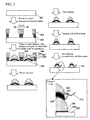
- a flat supporting substrate 201 is coated separately with two types of electron beam positive resists 202 and 203 by a spin coating method.
- a glass substrate, a sapphire substrate, a resin substrate, or the like is used as the flat supporting substrate.
- a quartz substrate or a sapphire substrate having excellent light transmittance can be used if it is necessary to irradiate the device with excitation light from the rear surface opposed to the surface on which the metal structure is formed.
- a combination of polymethyl methacrylate and a macromolecular resist having a structure capable of easy depolymerization by radical cutting can be used as the two types of electron beam positive resists.
- the resist it is preferable that the resist be capable of undergoing prebaking by a hot plate at 170° to 200 ° for about 2 to 5 minutes and also capable of undergoing electron beam writing at an electron dose of 2 0 ⁇ C/cm 2 to 50 ⁇ C/cm 2 at an accelerating voltage of 20 KV as a matter of practicality, and for example, the resists include ZEP-520A (available from Zeon Corporation).
- Alignment takes place using the position of a marker on the substrate and then, a direct electron beam exposure takes place twice, and thereby, a through hole is formed in each of the resists so that a hole diameter of the resist 202 closer to the substrate is larger than that of the resist 203.
- the through holes having a diameter of 300 nm and a diameter of 250 nm, respectively, are formed.
- the through holes are used for a mask for deposition having a large taper.
- the through holes depend on molecularity of nucleic acid that can be analyzed by parallel processing, and a pitch of about 1 ⁇ m is suitable, allowing for ease and simplicity of fabrication, yield, and the molecularity of nucleic acid that can be analyzed by parallel processing.
- a region where the through holes are formed depends on the molecularity of nucleic acid that can be analyzed by parallel processing, and also depends greatly on the position accuracy of the detector and the position resolution thereof. For example, if a reaction site (namely, the metal structure) is configured at a pitch of 1 ⁇ m, one million reaction sites can be formed, provided that the region where the through holes are formed is 1 mm ⁇ 1 mm.
- titanium 204, gold 205, titanium 206, a SiO 2 film 207, titanium 208, and gold 209 are deposited by sputtering according to the composition of the metal structure.
- the titanium is used in order to reinforce a bond between the sapphire and the gold and a bond between the gold and SiO 2 or other metal such as chromium may be used.
- the gold 209 is subjected to etching so that the titanium 208 is exposed.
- wet etching is used for the etching of the gold 209, and preferably, an iodine-base etchant is used as an etchant therefor.
- the iodine-base etchant is formed of iodine and iodide (e.g., potassium iodide or ammonium iodide), and has the advantage of being easy to treat because of being neutral and also has the advantage of facilitating control of an etching rate by component density.
- the etchants include AURUM-301 (available from Kanto Chemical Co., Inc.). Then, the titanium 208, the SiO 2 film 207 and the titanium 206 are subjected to dry etching so that the lower gold 205 is exposed. For this etching, it is preferable that argon plasma etching be used.
- the gold is again subjected to wet etching so that the width of the gold 205 lies between about 100 nm and 500 nm. It is required that the final size of the gold 205 be adjusted by the wavelength of light for irradiation for generation of the localized surface plasmon. For example, if light of about 500 nm is used, it is effective that the width lies between about 50 nm and 500 nm and the height lies between about 50 nm and 500 nm.
- the DNA probe is immobilized on the SiO 2 film 207. Although various methods for immobilization can possibly be used, a method using an aminosilane process will be described as an example. In the aminosilane process, an amino group is introduced into the SiO 2 film 207.
- biotin-succinimide e.g., NHS-Biotin available from Pierce Corporation
- streptoavidin is allowed to undergo a reaction
- a DNA probe 210 whose end is premodified with biotin is allowed to undergo a reaction, and thereby the nucleic acid analysis device having the DNA probe immobilized between the two metal structures in proximity to each other can be brought into completion.
- the length of the DNA probe is not particularly limited; however, an excessively long or short length of the DNA probe can possibly lead to the hiding of DNA behind the metal structures, resulting in impairment of the efficiency of hybridization with a nucleic acid sample.
- the number of bases lies between 20 and 50. It goes without saying that the above fabrication method may be used in the same manner even if silver or platinum, besides gold, is used.
- a flat supporting substrate 301 is coated separately with two types of electron beam positive resists 302 and 303 by spin coating method.
- a glass substrate, a sapphire substrate, a resin substrate, or the like is used as the flat supporting substrate.
- a quartz substrate or a sapphire substrate having excellent light transmittance can be used if it is necessary to irradiate the device with excitation light from the rear surface opposed to the surface on which the metal structure is formed and the opposite rear surface.
- a combination of polymethyl methacrylate and a macromolecular resist having a structure capable of easy depolymerization by radical cutting can be used as the two types of electron beam positive resists.
- the resist it is preferable that the resist be capable of undergoing prebaking by a hot plate at 170 ° to 200° for about 2 to 5 minutes and also capable of undergoing electron beam writing at an electron dose of 20 ⁇ C/cm 2 to 50 ⁇ C/cm 2 at an accelerating voltage of 20 KV as a matter of practicality, and for example, the resists include ZEP-520A (available from Zeon Corporation).
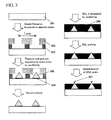
- Alignment takes place using the position of a marker on the substrate and then, a direct electron beam exposure takes place twice, and thereby, a through hole is formed in each of the resists so that a hole diameter of the electron beam positive resist 302 closer to the substrate is larger than that of the electron beam positive resist 303.
- the through holes having a diameter of 300 nm and a diameter of 100 nm, respectively, are formed.
- the through holes are used for a mask for deposition having a large taper.
- titanium 304 and gold 305 are deposited by sputtering according to the composition of the metal structure.
- the titanium is used in order to reinforce a bond between the sapphire and the gold, or other metal such as chromium may be used.
- the gold sputtered film 305 has a conical shape as shown in Fig. 3 . To control the conical shape, it is effective that the two resists each have different film thicknesses and hole diameters.
- the SiO 2 film 306 is deposited by sputtering. Then, the SiO 2 film 306 is subjected to reactive ion etching (using CF 4 /O 2 ) so that the tip end of the gold 305 is exposed.
- Fig. 4 Description will be given with reference to Fig. 4 with regard to an example of a preferred configuration of the nucleic acid analysis device.
- Plural regions where metal structures are arranged in a lattice are mounted on a light-transmission supporting substrate 401.
- the metal structures are the two metal structures in proximity to each other between which the DNA probe is immobilized, or the metal structures having the structure having the DNA probe immobilized on the conical end made of gold, as previously mentioned.
- the pitch of arrangement can be appropriately set according to the nucleic acid sample to be analyzed, or specifications of the fluorescent detector.
- RNA of 400,000 molecules per cell is expressed, and thus, an analysis of the frequency of RNA expression can be done with sufficient accuracy as in the case of digital counting, so that about 8 analyses can be made on one substrate.
- the mounting of plural regions on the light-transmission supporting substrate 401 can be accomplished by covering the light-transmission supporting substrate 401 with a reaction chamber 403 having a fluid channel preformed therein.
- the reaction chamber 403 is made of a resin base such as PDMS (Polydimethylsiloxane) having a fluid channel 407 preformed therein, and is fixedly attached onto the device for use.
- PDMS Polydimethylsiloxane
- the reaction chamber 403 includes: a temperature regulating unit 404 that preserves and performs temperature control on the nucleic acid sample, a reaction enzyme, a buffer, a nucleotide substrate, or the like; a dispensing unit 405 that feeds out a reaction solution; a valve 406 that controls the flow of the solution; and a waste fluid tank 408.
- the temperature regulating unit is provided for temperature control.
- a cleaning solution is fed through the fluid channel of the reaction chamber 403 and accommodated in the waste fluid tank 408.
- nucleic acid analyzer Description will be given with regard to an embodiment of a nucleic acid analyzer. Description will be given with reference to Fig. 5 with regard to an example of a preferred configuration of the nucleic acid analyzer using the nucleic acid analysis device.
- a means for supplying nucleotide having fluorescent dye, a nucleic acid synthase, and the nucleic acid sample a means for irradiating the nucleic acid analysis device with light, and a luminescence detecting means for making a measurement on fluorescence of the fluorescent dye captured in a nucleic acid chain due to a nucleic acid elongation reaction induced by the coexistence of the nucleotide, the nucleic acid synthase, and the nucleic acid sample on the nucleic acid analysis device.
- the above-mentioned device 505 is installed in a reaction chamber composed of a cover plate 501, a detection window 502, and injection and discharge ports 503 and 504 that serve as solution change ports.
- PDMS Polydimethylsiloxane
- the thickness of the detection window 502 is set to 0.17 mm.
- laser light beams 510 and 509 from a YAG laser light source 507 (with a wavelength of 532 nm and an output of 20 mW) and a YAG laser light source 508 (with a wavelength of 355 nm and an output of 20 mW) only the light beam 509 is circularly polarized by a ⁇ /4 plate 511, and the two laser light beams are coaxially adjusted by a dichroic mirror 512 (that reflects light of 410 nm or less) are then focused by the lens 513, and thereafter the device 505 is irradiated with the light through a prism 514 at a critical angle or more.
- a localized surface plasmon is generated in the metal structure present on the surface of the device 505, and a phosphor of a target substance trapped by the DNA probe bonded to the metal structure is present in a fluorescence intensifying field.
- a phosphor is excited by laser light, and part of the intensified fluorescence exits through the detection window 502.
- the fluorescence exiting through the detection window 502 is changed into parallel light beams through an objective lens 515 (X60, NA: 1.35, operating distance: 0.15 mm), background light and excitation light are cut off by an optical filter 516, and the light beams are focused through an imaging lens 517 onto a two-dimensional CCD camera 518 to form an image.
- the nucleotide containing a 3'-O-allyl group as a protecting group at position 3' OH of ribose and bonded to the fluorescent dye through an allyl group at position 5 of pyrimidine or at position 7 of purine can be used as the nucleotide with the fluorescent dye, as disclosed in P.N.A.S. 2006, vol. 103, pp 19635-19640 . Since the allyl group is cut by light irradiation or by contact with palladium, quenching of the dye and control of the elongation reaction can be achieved at a time. Even for a consecutive reaction, it is not necessary to do cleaning for removal of unreacted nucleotide.
- the nucleotide does not have to contain the 3'-O-allyl group as the protecting group at position 3' OH of ribose, and the nucleotide bonded to the dye through a functional group capable of being cut by light irradiation can be used.
- the use of the nucleic acid analysis device according to the second embodiment for fabrication of the nucleic acid analyzer eliminates a need for the cleaning process, thus achieves a reduction in analysis time and simplification of the device and the analyzer, enables not only consecutive reaction method but also real-time measurement of the base elongation reaction, and thus achieves a great improvement in throughput as compared to the prior art.
- the maximum size of the fluorescence intensifying effect of the localized surface plasmon is substantially equivalent to the diameter of the structure, and is specifically equal to 20 nm.
- the size of the nucleic acid is 34 nm for 10 bases, and the nucleic acid corresponding to an intensifying field of 20 nm is equivalent to 58.8 bases (20 ⁇ 3.4 ⁇ 10 ⁇ 58.8). Therefore, the device according to the first embodiment has difficulty in nucleotide sequence determination for the nucleic acid longer than 58 bases, unless there is provided a contrivance such as rounding the elongated nucleic acid or widening the fluorescence intensifying field. If the read base length is short, the reference rate of obtained sequence information with database is low.
- a nucleic acid synthase for the analysis of the nucleic acid in the sample is disposed in the region of generation of a localized surface plasmon, as distinct from the first and second embodiments. This enables the immobilization of the nucleic acid synthase in the region on which the fluorescence intensifying effect is exerted, and thus enables reading of a longer base length. Description will be given below, centering on differences from the first and second embodiments.
- the influence of the fluorescence intensifying effect of the localized surface plasmon is exerted within a range of about 10 nm to 20 nm, and thus, when the localized surface plasmon is generated on the surface of a metal structure having the nucleic acid synthase 605 immobilized thereon, only the dye captured in the nucleic acid synthase 605 benefits from fluorescence intensification, so that a difference in fluorescence intensity arises between the captured dye and the suspended dye, or equivalently, the fluorescence intensity of the captured dye is several times to several tens of times or more times that of the suspended dye.
- the third embodiment is intended to find out a method for simple and easy immobilization of the nucleic acid synthase 605 in the region in which the localized surface plasmon is generated, and is also intended to provide a method capable of the fabrication of the regions on the order of tens of thousands to hundreds of thousands on the flat substrate 103. In the regions, the localized surface plasmon is generated as mentioned above.
- an insulating layer is sandwiched in between the metal structures, the distance between the metal structures is controlled by controlling the thickness of the insulating layer, and the nucleic acid synthase is immobilized on the insulating layer.
- An inorganic material such as SiO 2 or an organic material represented by polyimide can be used for the insulating layer to be interposed between the metal structures.
- the fabrication of the desired metal structure with the nucleic acid synthase can be accomplished, using a difference in chemical properties between the surface of the insulating layer and the surface of the metal, by selecting an appropriate functional group, and either imparting the functional group to the insulating layer or allowing a functional group present in the nucleic acid synthase or a new functional group introduced into the nucleic acid synthase to react with the metal structure.
- the metal structure may be configured so that the structure has a sharp tip, the metal structure is coated with different metal from the above-mentioned metal in order that only the tip is exposed, and the difference in adhesion to the nucleic acid synthase between the above-mentioned metal and a material that coats it is utilized for immobilization of the nucleic acid synthase only on the tip of the metal.
- the nucleic acid synthase For immobilization of the nucleic acid synthase on the exposed portion, a difference in chemical properties between the surface of the metal structure and the surface of the thin film can be utilized. For example, if gold is used as the metal and SiO 2 is used for the film that coats the metal, the nucleic acid synthase is immobilized only on the gold exposed portion by allowing the functional group present in the nucleic acid synthase or the new functional group introduced into the nucleic acid synthase to react with the functional group introduced on the surface of the gold.
- the appropriate size of the metal structure varies according to the wavelength of light for irradiation.
- a resonance frequency suitable for surface plasmon generation depends on the interaction between a group of free electrons and light on the surface of the metal structure. If visible light is used as excitation light, it is appropriate that the dimensions of the metal structure are such that both the width and height thereof lie between about 30 nm and 1000 nm; however, it is to be understood that the dimensions are not restricted to this condition. Also, the effect of the surface plasmon is equivalent even if the thin film that coats the metal structure is removed after the immobilization of the nucleic acid synthase on the tip by the above method. Preferably, the thin film that coats the metal structure is removed if the thin film adversely affects the properties of the nucleic acid analysis device.
- the nucleic acid synthase is not particularly limited, provided that it is capable of elongation of the nucleic acid.
- Such nucleic acid synthases include various DNA polymerases if the nucleic acid is DNA.
- such nucleic acid synthases include various RNA polymerases if the nucleic acid is RNA.
- N-(4-Maleimidobutyryloxy) succinimide e.g., GMBS commercially available from Dojindo Laboratories
- GMBS commercially available from Dojindo Laboratories
- the nucleic acid synthase is allowed to undergo a reaction.
- the nucleic acid analysis device having the nucleic acid synthase immobilized between the two metal structures in proximity to each other can be brought into completion.
- the above method is only illustrative, and a method utilizing physical adsorption to nitrocellulose, polyacrylamide, or the like, a method utilizing a specific affinity between histidine and nickel ion or cobalt ion, a method utilizing a biotin-avidin bond, or the like may be used.
- the metal structure can be fabricated in the same manner even if silver or platinum is used for the metal structure.
- the SiO 2 film 306 is subjected to reactive ion etching (using CF 4 /O 2 ) so that the tip end of the gold 305 is exposed. Then, by a hydroxysilane process, a hydroxyl group is introduced on the SiO 2 film 306 to thereby prevent non-singular adsorption.
- a SAM Self-Assembled Monolayer
- an amino group is introduced on the surface of the gold
- a functional group that can be allowed to react with a thiol group is introduced by use of N-(4-Maleimidobutyryloxy) succinimide (e.g., GMBS commercially available from Dojindo Laboratories).
- N-(4-Maleimidobutyryloxy) succinimide e.g., GMBS commercially available from Dojindo Laboratories.
- GMBS N-(4-Maleimidobutyryloxy) succinimide
- the above method is only illustrative, and a method utilizing physical adsorption to nitrocellulose, polyacrylamide, or the like, a method utilizing a specific affinity between histidine and nickel ion or cobalt ion, a method utilizing a biotin-avidin bond, or the like may be used.
- the metal structure can be fabricated in the same manner even if silver or platinum is used for the metal structure.
- analysis by the nucleic acid analysis device described with reference to the third embodiment can also be performed by the nucleic acid analyzer equivalent to the second embodiment. Since the third embodiment is different from the second embodiment only in that the nucleic acid synthase is replaced by a primer, description thereof will be omitted.
- the analyzer includes a means for supplying nucleotide having fluorescent dye, a primer and a nucleic acid sample to the nucleic acid analysis device; a means for irradiating the nucleic acid analysis device with light; and a luminescence detecting means for making a measurement on fluorescence of the fluorescent dye captured in a nucleic acid chain due to a nucleic acid elongation reaction induced by the coexistence of the nucleotide, the primer and the nucleic acid sample on the nucleic acid analysis device.
- the embodiments may be appropriately used in combination.
Landscapes
- Health & Medical Sciences (AREA)
- Chemical & Material Sciences (AREA)
- Immunology (AREA)
- Physics & Mathematics (AREA)
- General Physics & Mathematics (AREA)
- Analytical Chemistry (AREA)
- Biochemistry (AREA)
- General Health & Medical Sciences (AREA)
- Life Sciences & Earth Sciences (AREA)
- Nuclear Medicine, Radiotherapy & Molecular Imaging (AREA)
- Pathology (AREA)
- Chemical Kinetics & Catalysis (AREA)
- Optics & Photonics (AREA)
- Investigating, Analyzing Materials By Fluorescence Or Luminescence (AREA)
- Apparatus Associated With Microorganisms And Enzymes (AREA)
- Investigating Or Analysing Materials By The Use Of Chemical Reactions (AREA)
- Measuring Or Testing Involving Enzymes Or Micro-Organisms (AREA)
Priority Applications (1)
| Application Number | Priority Date | Filing Date | Title |
|---|---|---|---|
| EP20110008104 EP2423672B1 (de) | 2007-07-20 | 2008-07-15 | Nucleinsäure-Analysevorrichtung |
Applications Claiming Priority (2)
| Application Number | Priority Date | Filing Date | Title |
|---|---|---|---|
| JP2007188989 | 2007-07-20 | ||
| JP2008079494A JP5222599B2 (ja) | 2007-07-20 | 2008-03-26 | 核酸分析デバイス及びそれを用いた核酸分析装置 |
Related Child Applications (1)
| Application Number | Title | Priority Date | Filing Date |
|---|---|---|---|
| EP11008104.9 Division-Into | 2011-10-06 |
Publications (3)
| Publication Number | Publication Date |
|---|---|
| EP2019309A2 true EP2019309A2 (de) | 2009-01-28 |
| EP2019309A3 EP2019309A3 (de) | 2009-03-11 |
| EP2019309B1 EP2019309B1 (de) | 2013-04-24 |
Family
ID=39873896
Family Applications (2)
| Application Number | Title | Priority Date | Filing Date |
|---|---|---|---|
| EP20080012794 Not-in-force EP2019309B1 (de) | 2007-07-20 | 2008-07-15 | Nucleinsäure-Analysevorrichtung und Nucleinsäure-Analysator damit |
| EP20110008104 Not-in-force EP2423672B1 (de) | 2007-07-20 | 2008-07-15 | Nucleinsäure-Analysevorrichtung |
Family Applications After (1)
| Application Number | Title | Priority Date | Filing Date |
|---|---|---|---|
| EP20110008104 Not-in-force EP2423672B1 (de) | 2007-07-20 | 2008-07-15 | Nucleinsäure-Analysevorrichtung |
Country Status (4)
| Country | Link |
|---|---|
| US (1) | US8865459B2 (de) |
| EP (2) | EP2019309B1 (de) |
| JP (1) | JP5222599B2 (de) |
| CN (2) | CN103451086B (de) |
Cited By (7)
| Publication number | Priority date | Publication date | Assignee | Title |
|---|---|---|---|---|
| US9145583B2 (en) | 2009-08-18 | 2015-09-29 | Avellino Co., Ltd. | Multi-spot metal-capped nanostructure array nucleic acid chip for diagnosis of corneal dystrophy and preparation method thereof |
| US9856516B2 (en) | 2013-03-15 | 2018-01-02 | Avellino Labs Usa, Inc. | Methods for improved isolation of genomic DNA templates for allele detection |
| US9938581B2 (en) | 2009-04-17 | 2018-04-10 | Avellino Co., Ltd. | Primers for diagnosing Avellino corneal dystrophy |
| US9970051B2 (en) | 2010-10-01 | 2018-05-15 | Avellino Co., Ltd. | System for diagnosing Avellino corneal dystrophy |
| US10889850B2 (en) | 2013-03-15 | 2021-01-12 | Avellino Lab Usa, Inc. | Methods for improved isolation of genomic DNA templates for allele detection |
| US11525160B2 (en) | 2013-11-15 | 2022-12-13 | Avellino Lab Usa, Inc. | Methods for multiplex detection of alleles associated with ophthalmic conditions |
| US11987809B2 (en) | 2015-11-13 | 2024-05-21 | Avellino Lab Usa, Inc. | Methods for the treatment of corneal dystrophies |
Families Citing this family (25)
| Publication number | Priority date | Publication date | Assignee | Title |
|---|---|---|---|---|
| JP5022873B2 (ja) * | 2007-11-22 | 2012-09-12 | 株式会社日立ハイテクノロジーズ | 核酸分析方法、及び核酸分析装置 |
| JP5707030B2 (ja) * | 2009-04-02 | 2015-04-22 | 株式会社日立ハイテクノロジーズ | 核酸分析デバイス、及び核酸分析装置 |
| JP5462548B2 (ja) * | 2009-08-12 | 2014-04-02 | 株式会社日立ハイテクノロジーズ | 核酸分析素子及びそれを用いた核酸分析装置 |
| EP2513630B1 (de) * | 2009-12-17 | 2016-05-25 | Chris Geddes | Detektionssystem umfassend mischmetallsubstrate zur metallverstärkten fluoreszenz |
| JP5309092B2 (ja) * | 2010-07-20 | 2013-10-09 | 株式会社日立ハイテクノロジーズ | 核酸分析用デバイス,核酸分析装置、及び核酸分析用デバイスの製造方法 |
| JP5651485B2 (ja) * | 2011-01-14 | 2015-01-14 | 株式会社日立ハイテクノロジーズ | 核酸分析装置 |
| EP2711689B1 (de) * | 2011-05-19 | 2020-01-01 | Konica Minolta, Inc. | Oberflächenplasmonenfeldverstärkte fluoreszenzmessvorrichtung und fluoreszenznachweisverfahren damit |
| JP5692164B2 (ja) * | 2012-05-22 | 2015-04-01 | ウシオ電機株式会社 | マイクロチップへの試薬供給方法及びマイクロチップへの試薬供給装置 |
| CN102703312B (zh) * | 2012-05-24 | 2014-03-19 | 中国科学院北京基因组研究所 | 一种dna测序仪 |
| WO2014188887A1 (ja) * | 2013-05-24 | 2014-11-27 | 株式会社日立ハイテクノロジーズ | 核酸分析装置及びそれを用いた核酸分析方法 |
| WO2015074001A1 (en) * | 2013-11-17 | 2015-05-21 | Quantum-Si Incorporated | Optical system and assay chip for probing, detecting and analyzing molecules |
| JP6185151B2 (ja) * | 2014-04-03 | 2017-08-23 | 株式会社日立ハイテクノロジーズ | 分析装置 |
| US9804093B2 (en) * | 2014-05-23 | 2017-10-31 | University Of Notre Dame Du Lac | Ultrasensitive SERS flow detector |
| JP6466966B2 (ja) * | 2014-11-27 | 2019-02-06 | 株式会社日立ハイテクノロジーズ | スポットアレイ基板の製造方法 |
| US9733188B2 (en) * | 2015-09-21 | 2017-08-15 | International Business Machines Corporation | Enhancing on-chip fluorescence detection |
| CN106841135B (zh) * | 2017-01-06 | 2019-05-31 | 东南大学 | 一种通过荧光法同时检测多种miRNA的方法 |
| CN109414673B (zh) | 2017-02-01 | 2021-09-07 | 伊鲁米那股份有限公司 | 具有响应于多个激发频率的基准的系统和方法 |
| GB201701689D0 (en) | 2017-02-01 | 2017-03-15 | Illumia Inc | System and method with fiducials of non-closed shapes |
| GB201701686D0 (en) | 2017-02-01 | 2017-03-15 | Illunina Inc | System & method with fiducials having offset layouts |
| GB201701688D0 (en) | 2017-02-01 | 2017-03-15 | Illumia Inc | System and method with fiducials in non-recliner layouts |
| GB201701691D0 (en) * | 2017-02-01 | 2017-03-15 | Illumina Inc | System and method with reflective fiducials |
| BR112020000826A2 (pt) | 2017-07-24 | 2020-07-21 | Quantum-Si Incorporated | instrumento bio-optoeletrônico maciçamente paralelo portátil |
| CN108776126B (zh) * | 2018-08-13 | 2020-11-27 | 长沙学院 | 表面等离子增强荧光传感器及折射率变化测量方法 |
| JP2022524888A (ja) * | 2019-03-29 | 2022-05-10 | ファセ ホログラフィック イマイング ペーホーイー アクティエボラーグ | 顕微鏡観察のためのマイクロプレート |
| CN110618127B (zh) * | 2019-09-29 | 2020-09-01 | 中国农业大学 | 一种核酸探针检测农药自动变色的装置 |
Family Cites Families (28)
| Publication number | Priority date | Publication date | Assignee | Title |
|---|---|---|---|---|
| GB8423204D0 (en) | 1984-09-14 | 1984-10-17 | Comtech Res Unit | Assay technique and equipment |
| US20020022261A1 (en) * | 1995-06-29 | 2002-02-21 | Anderson Rolfe C. | Miniaturized genetic analysis systems and methods |
| JPH10267841A (ja) * | 1997-03-24 | 1998-10-09 | Kokuritsu Shintai Shogaisha Rehabilitation Center Souchiyou | 表面プラズモン共鳴センシングデバイス |
| JP3380744B2 (ja) * | 1998-05-19 | 2003-02-24 | 株式会社日立製作所 | センサおよびこれを利用した測定装置 |
| US7056661B2 (en) * | 1999-05-19 | 2006-06-06 | Cornell Research Foundation, Inc. | Method for sequencing nucleic acid molecules |
| JP3783826B2 (ja) * | 2000-01-17 | 2006-06-07 | 横河電機株式会社 | バイオチップ読み取り装置 |
| JP3525142B2 (ja) * | 2001-01-12 | 2004-05-10 | 独立行政法人 科学技術振興機構 | 金属ナノウェルを用いた蛍光分析用素子及びその製造方法 |
| GB0112238D0 (en) * | 2001-05-18 | 2001-07-11 | Medical Biosystems Ltd | Sequencing method |
| WO2004068141A1 (en) | 2003-01-22 | 2004-08-12 | The Arizona Board Of Regents On Behalf Of The University Of Arizona | Coupled plasmon-waveguide resonance spectroscopic sensors for pharmaceutical and chemical testing |
| EP1445601A3 (de) | 2003-01-30 | 2004-09-22 | Fuji Photo Film Co., Ltd. | Messchips für lokale Oberflächenplasmonenresonanzmesssensoren, Herstellungsverfahren für diese Messchips und Sensoren welche diese Chips verwenden |
| JP4218016B2 (ja) * | 2003-03-26 | 2009-02-04 | セイコーエプソン株式会社 | 核酸固定化方法およびそれを用いるバイオセンサの製造法 |
| GB0318808D0 (en) * | 2003-08-11 | 2003-09-10 | Toshiba Res Europ Ltd | An encoded carrier |
| US6870237B1 (en) * | 2003-08-26 | 2005-03-22 | National Taiwan University | Repeated structure of nanometer thin films with symmetric or asymmetric configuration for SPR signal modulation |
| US20050064432A1 (en) * | 2003-09-19 | 2005-03-24 | Linden Technologies, Inc. | Nucleic acid amplification and detection |
| JP4328167B2 (ja) * | 2003-10-02 | 2009-09-09 | ソニー株式会社 | 突起する対向電極を利用する物質間の相互作用検出部と該検出部が設けられたバイオアッセイ用基板 |
| JP4163606B2 (ja) * | 2003-12-10 | 2008-10-08 | 富士フイルム株式会社 | 微細構造体、微細構造体の作製方法、ラマン分光方法および装置 |
| JP4109205B2 (ja) | 2004-01-07 | 2008-07-02 | 富士フイルム株式会社 | 被検体検出方法 |
| JP4463610B2 (ja) | 2004-04-23 | 2010-05-19 | ローム株式会社 | 表面プラズモン共鳴センサ装置 |
| JP2005337771A (ja) * | 2004-05-25 | 2005-12-08 | National Institute For Materials Science | ナノ構造を有する集積化ピラー構造光学素子 |
| US7476787B2 (en) * | 2005-02-23 | 2009-01-13 | Stc.Unm | Addressable field enhancement microscopy |
| EP1869219A4 (de) * | 2005-03-31 | 2010-06-23 | Perkinelmer Las Inc | Multiplex-testsystem |
| US8048789B2 (en) | 2005-04-26 | 2011-11-01 | Northwestern University | Mesoscale pyramids, arrays and methods of preparation |
| WO2007015556A1 (en) | 2005-08-01 | 2007-02-08 | Canon Kabushiki Kaisha | Target substance detecting device, target substance detecting method using the same, and detecting apparatus and kit therefor |
| JP2007171003A (ja) | 2005-12-22 | 2007-07-05 | Fujifilm Corp | 質量分析用基板並びに分析方法および装置 |
| JP2007240361A (ja) | 2006-03-09 | 2007-09-20 | Sekisui Chem Co Ltd | 局在プラズモン増強センサ |
| US7709808B2 (en) * | 2006-05-16 | 2010-05-04 | Applied Biosystems, Llc | Systems, methods and apparatus for single molecule sequencing |
| US7898659B2 (en) * | 2006-12-11 | 2011-03-01 | Fujifilm Corporation | Surface plasmon sensor, sensing apparatus and sensing method |
| WO2009038791A1 (en) * | 2007-09-18 | 2009-03-26 | Applied Biosystems Inc. | Methods, systems and apparatus for light concentrating mechanisms |
-
2008
- 2008-03-26 JP JP2008079494A patent/JP5222599B2/ja not_active Expired - Fee Related
- 2008-07-15 EP EP20080012794 patent/EP2019309B1/de not_active Not-in-force
- 2008-07-15 EP EP20110008104 patent/EP2423672B1/de not_active Not-in-force
- 2008-07-15 US US12/173,472 patent/US8865459B2/en not_active Expired - Fee Related
- 2008-07-18 CN CN201310337180.8A patent/CN103451086B/zh not_active Expired - Fee Related
- 2008-07-18 CN CNA2008101333406A patent/CN101349645A/zh active Pending
Non-Patent Citations (1)
| Title |
|---|
| P.N.A.S., vol. 100, 2003, pages 3960 - 3964 |
Cited By (8)
| Publication number | Priority date | Publication date | Assignee | Title |
|---|---|---|---|---|
| US9938581B2 (en) | 2009-04-17 | 2018-04-10 | Avellino Co., Ltd. | Primers for diagnosing Avellino corneal dystrophy |
| US11268146B2 (en) | 2009-04-17 | 2022-03-08 | Avellino Co., Ltd. | Primers for diagnosing Avellino corneal dystrophy |
| US9145583B2 (en) | 2009-08-18 | 2015-09-29 | Avellino Co., Ltd. | Multi-spot metal-capped nanostructure array nucleic acid chip for diagnosis of corneal dystrophy and preparation method thereof |
| US9970051B2 (en) | 2010-10-01 | 2018-05-15 | Avellino Co., Ltd. | System for diagnosing Avellino corneal dystrophy |
| US9856516B2 (en) | 2013-03-15 | 2018-01-02 | Avellino Labs Usa, Inc. | Methods for improved isolation of genomic DNA templates for allele detection |
| US10889850B2 (en) | 2013-03-15 | 2021-01-12 | Avellino Lab Usa, Inc. | Methods for improved isolation of genomic DNA templates for allele detection |
| US11525160B2 (en) | 2013-11-15 | 2022-12-13 | Avellino Lab Usa, Inc. | Methods for multiplex detection of alleles associated with ophthalmic conditions |
| US11987809B2 (en) | 2015-11-13 | 2024-05-21 | Avellino Lab Usa, Inc. | Methods for the treatment of corneal dystrophies |
Also Published As
| Publication number | Publication date |
|---|---|
| EP2019309A3 (de) | 2009-03-11 |
| JP5222599B2 (ja) | 2013-06-26 |
| CN103451086B (zh) | 2015-03-04 |
| US8865459B2 (en) | 2014-10-21 |
| CN101349645A (zh) | 2009-01-21 |
| JP2009045057A (ja) | 2009-03-05 |
| US20090023202A1 (en) | 2009-01-22 |
| CN103451086A (zh) | 2013-12-18 |
| EP2019309B1 (de) | 2013-04-24 |
| EP2423672B1 (de) | 2013-07-03 |
| EP2423672A1 (de) | 2012-02-29 |
Similar Documents
| Publication | Publication Date | Title |
|---|---|---|
| EP2423672B1 (de) | Nucleinsäure-Analysevorrichtung | |
| US7013054B2 (en) | Waveguides for performing spectroscopy with confined effective observation volumes | |
| US6790671B1 (en) | Optically characterizing polymers | |
| JP5827360B2 (ja) | 装置及び方法 | |
| CN101393123B (zh) | 用于检测靶物质的分析装置、分析方法、或其中使用的器件 | |
| US20080318243A1 (en) | DNA measuring system and method | |
| CA2340228A1 (en) | Optically characterizing polymers | |
| WO2002014462A1 (en) | Biosensors and methods for their use | |
| JP5587816B2 (ja) | 核酸分析デバイス、及び核酸分析装置 | |
| US20160059202A1 (en) | Methods of making and using microarrays suitable for high-throughput detection | |
| US8865403B2 (en) | Nucleic acid analyzing device and nucleic acid analyzer | |
| JP2007525977A (ja) | 単一分子の分離、配置、およびシークエンシング | |
| JP5309092B2 (ja) | 核酸分析用デバイス,核酸分析装置、及び核酸分析用デバイスの製造方法 | |
| JP5097495B2 (ja) | 生体分子検出素子及び生体分子検出素子の製造方法 | |
| US7226794B2 (en) | Surface-enhanced Raman spectroscopy for biosensor systems and methods for determining the presence of biomolecules | |
| JP5026359B2 (ja) | 核酸分析デバイス、核酸分析装置及び核酸分析方法 | |
| JP5022873B2 (ja) | 核酸分析方法、及び核酸分析装置 | |
| WO2006134376A2 (en) | Flag free chemical capture detection | |
| JP2011038932A (ja) | 核酸分析素子及びそれを用いた核酸分析装置 | |
| CN121994771A (zh) | Sers基底、其制备方法与集成微流控检测系统 | |
| JP2011257224A (ja) | 核酸分析デバイス、およびその製造方法 |
Legal Events
| Date | Code | Title | Description |
|---|---|---|---|
| PUAI | Public reference made under article 153(3) epc to a published international application that has entered the european phase |
Free format text: ORIGINAL CODE: 0009012 |
|
| AK | Designated contracting states |
Kind code of ref document: A2 Designated state(s): AT BE BG CH CY CZ DE DK EE ES FI FR GB GR HR HU IE IS IT LI LT LU LV MC MT NL NO PL PT RO SE SI SK TR |
|
| AX | Request for extension of the european patent |
Extension state: AL BA MK RS |
|
| PUAL | Search report despatched |
Free format text: ORIGINAL CODE: 0009013 |
|
| AK | Designated contracting states |
Kind code of ref document: A3 Designated state(s): AT BE BG CH CY CZ DE DK EE ES FI FR GB GR HR HU IE IS IT LI LT LU LV MC MT NL NO PL PT RO SE SI SK TR |
|
| AX | Request for extension of the european patent |
Extension state: AL BA MK RS |
|
| 17P | Request for examination filed |
Effective date: 20090910 |
|
| 17Q | First examination report despatched |
Effective date: 20091008 |
|
| AKX | Designation fees paid |
Designated state(s): AT BE BG CH CY CZ DE DK EE ES FI FR GB GR HR HU IE IS IT LI LT LU LV MC MT NL NO PL PT RO SE SI SK TR |
|
| 17Q | First examination report despatched |
Effective date: 20100318 |
|
| GRAP | Despatch of communication of intention to grant a patent |
Free format text: ORIGINAL CODE: EPIDOSNIGR1 |
|
| GRAS | Grant fee paid |
Free format text: ORIGINAL CODE: EPIDOSNIGR3 |
|
| GRAA | (expected) grant |
Free format text: ORIGINAL CODE: 0009210 |
|
| RIN1 | Information on inventor provided before grant (corrected) |
Inventor name: TAKAHASHI, SATOSHI Inventor name: SAITO, TOSHIRO Inventor name: NARAHARA, MASATOSHI |
|
| AK | Designated contracting states |
Kind code of ref document: B1 Designated state(s): AT BE BG CH CY CZ DE DK EE ES FI FR GB GR HR HU IE IS IT LI LT LU LV MC MT NL NO PL PT RO SE SI SK TR |
|
| REG | Reference to a national code |
Ref country code: GB Ref legal event code: FG4D |
|
| REG | Reference to a national code |
Ref country code: CH Ref legal event code: EP |
|
| REG | Reference to a national code |
Ref country code: AT Ref legal event code: REF Ref document number: 608879 Country of ref document: AT Kind code of ref document: T Effective date: 20130515 |
|
| REG | Reference to a national code |
Ref country code: IE Ref legal event code: FG4D |
|
| REG | Reference to a national code |
Ref country code: DE Ref legal event code: R096 Ref document number: 602008023997 Country of ref document: DE Effective date: 20130627 |
|
| REG | Reference to a national code |
Ref country code: AT Ref legal event code: MK05 Ref document number: 608879 Country of ref document: AT Kind code of ref document: T Effective date: 20130424 |
|
| REG | Reference to a national code |
Ref country code: LT Ref legal event code: MG4D |
|
| REG | Reference to a national code |
Ref country code: NL Ref legal event code: VDEP Effective date: 20130424 |
|
| PG25 | Lapsed in a contracting state [announced via postgrant information from national office to epo] |
Ref country code: ES Free format text: LAPSE BECAUSE OF FAILURE TO SUBMIT A TRANSLATION OF THE DESCRIPTION OR TO PAY THE FEE WITHIN THE PRESCRIBED TIME-LIMIT Effective date: 20130804 Ref country code: SE Free format text: LAPSE BECAUSE OF FAILURE TO SUBMIT A TRANSLATION OF THE DESCRIPTION OR TO PAY THE FEE WITHIN THE PRESCRIBED TIME-LIMIT Effective date: 20130424 Ref country code: IS Free format text: LAPSE BECAUSE OF FAILURE TO SUBMIT A TRANSLATION OF THE DESCRIPTION OR TO PAY THE FEE WITHIN THE PRESCRIBED TIME-LIMIT Effective date: 20130824 Ref country code: SI Free format text: LAPSE BECAUSE OF FAILURE TO SUBMIT A TRANSLATION OF THE DESCRIPTION OR TO PAY THE FEE WITHIN THE PRESCRIBED TIME-LIMIT Effective date: 20130424 Ref country code: NO Free format text: LAPSE BECAUSE OF FAILURE TO SUBMIT A TRANSLATION OF THE DESCRIPTION OR TO PAY THE FEE WITHIN THE PRESCRIBED TIME-LIMIT Effective date: 20130724 Ref country code: FI Free format text: LAPSE BECAUSE OF FAILURE TO SUBMIT A TRANSLATION OF THE DESCRIPTION OR TO PAY THE FEE WITHIN THE PRESCRIBED TIME-LIMIT Effective date: 20130424 Ref country code: LT Free format text: LAPSE BECAUSE OF FAILURE TO SUBMIT A TRANSLATION OF THE DESCRIPTION OR TO PAY THE FEE WITHIN THE PRESCRIBED TIME-LIMIT Effective date: 20130424 Ref country code: AT Free format text: LAPSE BECAUSE OF FAILURE TO SUBMIT A TRANSLATION OF THE DESCRIPTION OR TO PAY THE FEE WITHIN THE PRESCRIBED TIME-LIMIT Effective date: 20130424 Ref country code: PT Free format text: LAPSE BECAUSE OF FAILURE TO SUBMIT A TRANSLATION OF THE DESCRIPTION OR TO PAY THE FEE WITHIN THE PRESCRIBED TIME-LIMIT Effective date: 20130826 Ref country code: BE Free format text: LAPSE BECAUSE OF FAILURE TO SUBMIT A TRANSLATION OF THE DESCRIPTION OR TO PAY THE FEE WITHIN THE PRESCRIBED TIME-LIMIT Effective date: 20130424 Ref country code: GR Free format text: LAPSE BECAUSE OF FAILURE TO SUBMIT A TRANSLATION OF THE DESCRIPTION OR TO PAY THE FEE WITHIN THE PRESCRIBED TIME-LIMIT Effective date: 20130725 |
|
| PG25 | Lapsed in a contracting state [announced via postgrant information from national office to epo] |
Ref country code: LV Free format text: LAPSE BECAUSE OF FAILURE TO SUBMIT A TRANSLATION OF THE DESCRIPTION OR TO PAY THE FEE WITHIN THE PRESCRIBED TIME-LIMIT Effective date: 20130424 Ref country code: CY Free format text: LAPSE BECAUSE OF FAILURE TO SUBMIT A TRANSLATION OF THE DESCRIPTION OR TO PAY THE FEE WITHIN THE PRESCRIBED TIME-LIMIT Effective date: 20130424 Ref country code: HR Free format text: LAPSE BECAUSE OF FAILURE TO SUBMIT A TRANSLATION OF THE DESCRIPTION OR TO PAY THE FEE WITHIN THE PRESCRIBED TIME-LIMIT Effective date: 20130424 Ref country code: PL Free format text: LAPSE BECAUSE OF FAILURE TO SUBMIT A TRANSLATION OF THE DESCRIPTION OR TO PAY THE FEE WITHIN THE PRESCRIBED TIME-LIMIT Effective date: 20130424 Ref country code: BG Free format text: LAPSE BECAUSE OF FAILURE TO SUBMIT A TRANSLATION OF THE DESCRIPTION OR TO PAY THE FEE WITHIN THE PRESCRIBED TIME-LIMIT Effective date: 20130724 |
|
| PG25 | Lapsed in a contracting state [announced via postgrant information from national office to epo] |
Ref country code: DK Free format text: LAPSE BECAUSE OF FAILURE TO SUBMIT A TRANSLATION OF THE DESCRIPTION OR TO PAY THE FEE WITHIN THE PRESCRIBED TIME-LIMIT Effective date: 20130424 Ref country code: EE Free format text: LAPSE BECAUSE OF FAILURE TO SUBMIT A TRANSLATION OF THE DESCRIPTION OR TO PAY THE FEE WITHIN THE PRESCRIBED TIME-LIMIT Effective date: 20130424 Ref country code: CZ Free format text: LAPSE BECAUSE OF FAILURE TO SUBMIT A TRANSLATION OF THE DESCRIPTION OR TO PAY THE FEE WITHIN THE PRESCRIBED TIME-LIMIT Effective date: 20130424 Ref country code: SK Free format text: LAPSE BECAUSE OF FAILURE TO SUBMIT A TRANSLATION OF THE DESCRIPTION OR TO PAY THE FEE WITHIN THE PRESCRIBED TIME-LIMIT Effective date: 20130424 |
|
| PG25 | Lapsed in a contracting state [announced via postgrant information from national office to epo] |
Ref country code: MC Free format text: LAPSE BECAUSE OF FAILURE TO SUBMIT A TRANSLATION OF THE DESCRIPTION OR TO PAY THE FEE WITHIN THE PRESCRIBED TIME-LIMIT Effective date: 20130424 Ref country code: NL Free format text: LAPSE BECAUSE OF FAILURE TO SUBMIT A TRANSLATION OF THE DESCRIPTION OR TO PAY THE FEE WITHIN THE PRESCRIBED TIME-LIMIT Effective date: 20130424 Ref country code: IT Free format text: LAPSE BECAUSE OF FAILURE TO SUBMIT A TRANSLATION OF THE DESCRIPTION OR TO PAY THE FEE WITHIN THE PRESCRIBED TIME-LIMIT Effective date: 20130424 Ref country code: RO Free format text: LAPSE BECAUSE OF FAILURE TO SUBMIT A TRANSLATION OF THE DESCRIPTION OR TO PAY THE FEE WITHIN THE PRESCRIBED TIME-LIMIT Effective date: 20130424 |
|
| PLBE | No opposition filed within time limit |
Free format text: ORIGINAL CODE: 0009261 |
|
| REG | Reference to a national code |
Ref country code: CH Ref legal event code: PL |
|
| STAA | Information on the status of an ep patent application or granted ep patent |
Free format text: STATUS: NO OPPOSITION FILED WITHIN TIME LIMIT |
|
| 26N | No opposition filed |
Effective date: 20140127 |
|
| REG | Reference to a national code |
Ref country code: IE Ref legal event code: MM4A |
|
| PG25 | Lapsed in a contracting state [announced via postgrant information from national office to epo] |
Ref country code: LI Free format text: LAPSE BECAUSE OF NON-PAYMENT OF DUE FEES Effective date: 20130731 Ref country code: CH Free format text: LAPSE BECAUSE OF NON-PAYMENT OF DUE FEES Effective date: 20130731 |
|
| REG | Reference to a national code |
Ref country code: DE Ref legal event code: R097 Ref document number: 602008023997 Country of ref document: DE Effective date: 20140127 |
|
| PG25 | Lapsed in a contracting state [announced via postgrant information from national office to epo] |
Ref country code: IE Free format text: LAPSE BECAUSE OF NON-PAYMENT OF DUE FEES Effective date: 20130715 |
|
| PG25 | Lapsed in a contracting state [announced via postgrant information from national office to epo] |
Ref country code: TR Free format text: LAPSE BECAUSE OF FAILURE TO SUBMIT A TRANSLATION OF THE DESCRIPTION OR TO PAY THE FEE WITHIN THE PRESCRIBED TIME-LIMIT Effective date: 20130424 Ref country code: MT Free format text: LAPSE BECAUSE OF FAILURE TO SUBMIT A TRANSLATION OF THE DESCRIPTION OR TO PAY THE FEE WITHIN THE PRESCRIBED TIME-LIMIT Effective date: 20130424 |
|
| PG25 | Lapsed in a contracting state [announced via postgrant information from national office to epo] |
Ref country code: HU Free format text: LAPSE BECAUSE OF FAILURE TO SUBMIT A TRANSLATION OF THE DESCRIPTION OR TO PAY THE FEE WITHIN THE PRESCRIBED TIME-LIMIT; INVALID AB INITIO Effective date: 20080715 Ref country code: LU Free format text: LAPSE BECAUSE OF NON-PAYMENT OF DUE FEES Effective date: 20130715 |
|
| REG | Reference to a national code |
Ref country code: FR Ref legal event code: PLFP Year of fee payment: 9 |
|
| REG | Reference to a national code |
Ref country code: FR Ref legal event code: PLFP Year of fee payment: 10 |
|
| REG | Reference to a national code |
Ref country code: FR Ref legal event code: PLFP Year of fee payment: 11 |
|
| REG | Reference to a national code |
Ref country code: DE Ref legal event code: R082 Ref document number: 602008023997 Country of ref document: DE Representative=s name: STREHL SCHUEBEL-HOPF & PARTNER MBB PATENTANWAE, DE Ref country code: DE Ref legal event code: R081 Ref document number: 602008023997 Country of ref document: DE Owner name: HITACHI HIGH-TECH CORPORATION, JP Free format text: FORMER OWNER: HITACHI HIGH-TECHNOLOGIES CORP., TOKYO, JP |
|
| PGFP | Annual fee paid to national office [announced via postgrant information from national office to epo] |
Ref country code: FR Payment date: 20200611 Year of fee payment: 13 |
|
| PGFP | Annual fee paid to national office [announced via postgrant information from national office to epo] |
Ref country code: DE Payment date: 20200630 Year of fee payment: 13 Ref country code: GB Payment date: 20200708 Year of fee payment: 13 |
|
| REG | Reference to a national code |
Ref country code: DE Ref legal event code: R119 Ref document number: 602008023997 Country of ref document: DE |
|
| GBPC | Gb: european patent ceased through non-payment of renewal fee |
Effective date: 20210715 |
|
| PG25 | Lapsed in a contracting state [announced via postgrant information from national office to epo] |
Ref country code: GB Free format text: LAPSE BECAUSE OF NON-PAYMENT OF DUE FEES Effective date: 20210715 Ref country code: DE Free format text: LAPSE BECAUSE OF NON-PAYMENT OF DUE FEES Effective date: 20220201 |
|
| PG25 | Lapsed in a contracting state [announced via postgrant information from national office to epo] |
Ref country code: FR Free format text: LAPSE BECAUSE OF NON-PAYMENT OF DUE FEES Effective date: 20210731 |