EP2019287A1 - Dispositif de mise à jour d'informations de positionnement du véhicule - Google Patents
Dispositif de mise à jour d'informations de positionnement du véhicule Download PDFInfo
- Publication number
- EP2019287A1 EP2019287A1 EP07743413A EP07743413A EP2019287A1 EP 2019287 A1 EP2019287 A1 EP 2019287A1 EP 07743413 A EP07743413 A EP 07743413A EP 07743413 A EP07743413 A EP 07743413A EP 2019287 A1 EP2019287 A1 EP 2019287A1
- Authority
- EP
- European Patent Office
- Prior art keywords
- vehicle
- updating
- assistance control
- positioning information
- map
- Prior art date
- Legal status (The legal status is an assumption and is not a legal conclusion. Google has not performed a legal analysis and makes no representation as to the accuracy of the status listed.)
- Granted
Links
- 231100000572 poisoning Toxicity 0.000 claims 1
- 230000000607 poisoning effect Effects 0.000 claims 1
- 238000013459 approach Methods 0.000 description 3
- 238000001514 detection method Methods 0.000 description 3
- 238000000605 extraction Methods 0.000 description 3
- 230000005540 biological transmission Effects 0.000 description 2
- 229910003460 diamond Inorganic materials 0.000 description 2
- 239000010432 diamond Substances 0.000 description 2
- 239000000284 extract Substances 0.000 description 2
- 238000005259 measurement Methods 0.000 description 2
- 230000001133 acceleration Effects 0.000 description 1
- 230000015556 catabolic process Effects 0.000 description 1
- 238000010276 construction Methods 0.000 description 1
- 238000006731 degradation reaction Methods 0.000 description 1
- 230000000694 effects Effects 0.000 description 1
- 230000012447 hatching Effects 0.000 description 1
- 239000003973 paint Substances 0.000 description 1
- 230000002123 temporal effect Effects 0.000 description 1
Images
Classifications
-
- G—PHYSICS
- G01—MEASURING; TESTING
- G01C—MEASURING DISTANCES, LEVELS OR BEARINGS; SURVEYING; NAVIGATION; GYROSCOPIC INSTRUMENTS; PHOTOGRAMMETRY OR VIDEOGRAMMETRY
- G01C21/00—Navigation; Navigational instruments not provided for in groups G01C1/00 - G01C19/00
- G01C21/38—Electronic maps specially adapted for navigation; Updating thereof
- G01C21/3804—Creation or updating of map data
- G01C21/3833—Creation or updating of map data characterised by the source of data
- G01C21/3844—Data obtained from position sensors only, e.g. from inertial navigation
-
- B—PERFORMING OPERATIONS; TRANSPORTING
- B60—VEHICLES IN GENERAL
- B60W—CONJOINT CONTROL OF VEHICLE SUB-UNITS OF DIFFERENT TYPE OR DIFFERENT FUNCTION; CONTROL SYSTEMS SPECIALLY ADAPTED FOR HYBRID VEHICLES; ROAD VEHICLE DRIVE CONTROL SYSTEMS FOR PURPOSES NOT RELATED TO THE CONTROL OF A PARTICULAR SUB-UNIT
- B60W10/00—Conjoint control of vehicle sub-units of different type or different function
- B60W10/18—Conjoint control of vehicle sub-units of different type or different function including control of braking systems
-
- B—PERFORMING OPERATIONS; TRANSPORTING
- B60—VEHICLES IN GENERAL
- B60W—CONJOINT CONTROL OF VEHICLE SUB-UNITS OF DIFFERENT TYPE OR DIFFERENT FUNCTION; CONTROL SYSTEMS SPECIALLY ADAPTED FOR HYBRID VEHICLES; ROAD VEHICLE DRIVE CONTROL SYSTEMS FOR PURPOSES NOT RELATED TO THE CONTROL OF A PARTICULAR SUB-UNIT
- B60W40/00—Estimation or calculation of non-directly measurable driving parameters for road vehicle drive control systems not related to the control of a particular sub unit, e.g. by using mathematical models
- B60W40/02—Estimation or calculation of non-directly measurable driving parameters for road vehicle drive control systems not related to the control of a particular sub unit, e.g. by using mathematical models related to ambient conditions
- B60W40/06—Road conditions
- B60W40/072—Curvature of the road
-
- B—PERFORMING OPERATIONS; TRANSPORTING
- B60—VEHICLES IN GENERAL
- B60W—CONJOINT CONTROL OF VEHICLE SUB-UNITS OF DIFFERENT TYPE OR DIFFERENT FUNCTION; CONTROL SYSTEMS SPECIALLY ADAPTED FOR HYBRID VEHICLES; ROAD VEHICLE DRIVE CONTROL SYSTEMS FOR PURPOSES NOT RELATED TO THE CONTROL OF A PARTICULAR SUB-UNIT
- B60W40/00—Estimation or calculation of non-directly measurable driving parameters for road vehicle drive control systems not related to the control of a particular sub unit, e.g. by using mathematical models
- B60W40/02—Estimation or calculation of non-directly measurable driving parameters for road vehicle drive control systems not related to the control of a particular sub unit, e.g. by using mathematical models related to ambient conditions
- B60W40/06—Road conditions
- B60W40/076—Slope angle of the road
-
- G—PHYSICS
- G01—MEASURING; TESTING
- G01C—MEASURING DISTANCES, LEVELS OR BEARINGS; SURVEYING; NAVIGATION; GYROSCOPIC INSTRUMENTS; PHOTOGRAMMETRY OR VIDEOGRAMMETRY
- G01C21/00—Navigation; Navigational instruments not provided for in groups G01C1/00 - G01C19/00
- G01C21/26—Navigation; Navigational instruments not provided for in groups G01C1/00 - G01C19/00 specially adapted for navigation in a road network
- G01C21/28—Navigation; Navigational instruments not provided for in groups G01C1/00 - G01C19/00 specially adapted for navigation in a road network with correlation of data from several navigational instruments
- G01C21/30—Map- or contour-matching
- G01C21/32—Structuring or formatting of map data
-
- G—PHYSICS
- G01—MEASURING; TESTING
- G01C—MEASURING DISTANCES, LEVELS OR BEARINGS; SURVEYING; NAVIGATION; GYROSCOPIC INSTRUMENTS; PHOTOGRAMMETRY OR VIDEOGRAMMETRY
- G01C21/00—Navigation; Navigational instruments not provided for in groups G01C1/00 - G01C19/00
- G01C21/38—Electronic maps specially adapted for navigation; Updating thereof
- G01C21/3804—Creation or updating of map data
- G01C21/3859—Differential updating map data
-
- G—PHYSICS
- G01—MEASURING; TESTING
- G01C—MEASURING DISTANCES, LEVELS OR BEARINGS; SURVEYING; NAVIGATION; GYROSCOPIC INSTRUMENTS; PHOTOGRAMMETRY OR VIDEOGRAMMETRY
- G01C21/00—Navigation; Navigational instruments not provided for in groups G01C1/00 - G01C19/00
- G01C21/38—Electronic maps specially adapted for navigation; Updating thereof
- G01C21/3863—Structures of map data
- G01C21/387—Organisation of map data, e.g. version management or database structures
-
- B—PERFORMING OPERATIONS; TRANSPORTING
- B60—VEHICLES IN GENERAL
- B60W—CONJOINT CONTROL OF VEHICLE SUB-UNITS OF DIFFERENT TYPE OR DIFFERENT FUNCTION; CONTROL SYSTEMS SPECIALLY ADAPTED FOR HYBRID VEHICLES; ROAD VEHICLE DRIVE CONTROL SYSTEMS FOR PURPOSES NOT RELATED TO THE CONTROL OF A PARTICULAR SUB-UNIT
- B60W50/00—Details of control systems for road vehicle drive control not related to the control of a particular sub-unit, e.g. process diagnostic or vehicle driver interfaces
- B60W2050/0062—Adapting control system settings
- B60W2050/0075—Automatic parameter input, automatic initialising or calibrating means
-
- B—PERFORMING OPERATIONS; TRANSPORTING
- B60—VEHICLES IN GENERAL
- B60W—CONJOINT CONTROL OF VEHICLE SUB-UNITS OF DIFFERENT TYPE OR DIFFERENT FUNCTION; CONTROL SYSTEMS SPECIALLY ADAPTED FOR HYBRID VEHICLES; ROAD VEHICLE DRIVE CONTROL SYSTEMS FOR PURPOSES NOT RELATED TO THE CONTROL OF A PARTICULAR SUB-UNIT
- B60W2552/00—Input parameters relating to infrastructure
- B60W2552/05—Type of road, e.g. motorways, local streets, paved or unpaved roads
-
- B—PERFORMING OPERATIONS; TRANSPORTING
- B60—VEHICLES IN GENERAL
- B60W—CONJOINT CONTROL OF VEHICLE SUB-UNITS OF DIFFERENT TYPE OR DIFFERENT FUNCTION; CONTROL SYSTEMS SPECIALLY ADAPTED FOR HYBRID VEHICLES; ROAD VEHICLE DRIVE CONTROL SYSTEMS FOR PURPOSES NOT RELATED TO THE CONTROL OF A PARTICULAR SUB-UNIT
- B60W2555/00—Input parameters relating to exterior conditions, not covered by groups B60W2552/00, B60W2554/00
- B60W2555/60—Traffic rules, e.g. speed limits or right of way
-
- B—PERFORMING OPERATIONS; TRANSPORTING
- B60—VEHICLES IN GENERAL
- B60W—CONJOINT CONTROL OF VEHICLE SUB-UNITS OF DIFFERENT TYPE OR DIFFERENT FUNCTION; CONTROL SYSTEMS SPECIALLY ADAPTED FOR HYBRID VEHICLES; ROAD VEHICLE DRIVE CONTROL SYSTEMS FOR PURPOSES NOT RELATED TO THE CONTROL OF A PARTICULAR SUB-UNIT
- B60W2556/00—Input parameters relating to data
- B60W2556/45—External transmission of data to or from the vehicle
- B60W2556/50—External transmission of data to or from the vehicle of positioning data, e.g. GPS [Global Positioning System] data
-
- G—PHYSICS
- G08—SIGNALLING
- G08G—TRAFFIC CONTROL SYSTEMS
- G08G1/00—Traffic control systems for road vehicles
- G08G1/09—Arrangements for giving variable traffic instructions
- G08G1/0962—Arrangements for giving variable traffic instructions having an indicator mounted inside the vehicle, e.g. giving voice messages
- G08G1/0967—Systems involving transmission of highway information, e.g. weather, speed limits
- G08G1/096708—Systems involving transmission of highway information, e.g. weather, speed limits where the received information might be used to generate an automatic action on the vehicle control
- G08G1/096716—Systems involving transmission of highway information, e.g. weather, speed limits where the received information might be used to generate an automatic action on the vehicle control where the received information does not generate an automatic action on the vehicle control
-
- G—PHYSICS
- G08—SIGNALLING
- G08G—TRAFFIC CONTROL SYSTEMS
- G08G1/00—Traffic control systems for road vehicles
- G08G1/09—Arrangements for giving variable traffic instructions
- G08G1/0962—Arrangements for giving variable traffic instructions having an indicator mounted inside the vehicle, e.g. giving voice messages
- G08G1/0967—Systems involving transmission of highway information, e.g. weather, speed limits
- G08G1/096733—Systems involving transmission of highway information, e.g. weather, speed limits where a selection of the information might take place
- G08G1/09675—Systems involving transmission of highway information, e.g. weather, speed limits where a selection of the information might take place where a selection from the received information takes place in the vehicle
-
- G—PHYSICS
- G08—SIGNALLING
- G08G—TRAFFIC CONTROL SYSTEMS
- G08G1/00—Traffic control systems for road vehicles
- G08G1/09—Arrangements for giving variable traffic instructions
- G08G1/0962—Arrangements for giving variable traffic instructions having an indicator mounted inside the vehicle, e.g. giving voice messages
- G08G1/0967—Systems involving transmission of highway information, e.g. weather, speed limits
- G08G1/096766—Systems involving transmission of highway information, e.g. weather, speed limits where the system is characterised by the origin of the information transmission
- G08G1/096791—Systems involving transmission of highway information, e.g. weather, speed limits where the system is characterised by the origin of the information transmission where the origin of the information is another vehicle
Definitions
- the present invention relates to a vehicle positioning information updating system, and in particular, to a vehicle positioning information updating system for updating positioning information concerning positioning of an own vehicle mounting an assistance unit which carries out assistance control according to the own vehicle position.
- a map database such as a CD or DVD storing road map data used for a navigation unit which carries out routing assistance or such, and a system for updating control data of a vehicle
- a system for updating control data of a vehicle for example, see a patent document 1.
- this system it is possible to respond to a temporal change in the map data, thus it is possible to present routing assistance or such from being carried out according to original old map data, as much as possible.
- it is possible to carry out appropriate assistance control according to a unique position of each vehicle it is possible to prevent optimum assistance control from not being carried out.
- Patent Document 1 Japanese Laid-Open Patent Application No. 10-181482
- mapping data is carried out regularly or irregularly.
- the updating may not be carried out according to repair of a road or such.
- the thus-updated map data may not correspond to a condition of a road for which repair has been made. Therefore, routing assistance or various types of assistance control in the vehicle may not be carried out appropriately.
- accuracy of route map data stored in the map database or a position of the own vehicle detected degrade, as time has elapsed or a moving distance of the vehicle becomes longer, after the updating. Therefore, when next updating is not carried out, assistance control of the vehicle with the use of the road map data and the own vehicle position, may not be carries out appropriately, due to the degradation in the accuracy.
- the present invention has been devised in consideration of the above-described point, and an object of the present invention is to provide a vehicle positioning information updating system by which assistance control can be appropriately carried out as a result of positioning information such as road map data or an own vehicle position being updated appropriately according to characteristics or a level of the assistance control.
- a vehicle positioning information updating system for updating positioning information concerning positioning of an own vehicle mounting an assistance control unit which carries out assistance control according to the own vehicle position, provided with an updating condition setting means configured to set an updating condition for updating the positioning information based on characteristics or a level of the assistance control by the assistance control unit; and an updating executing means configured to execute updating of the positioning information according to the updating condition set by the updating condition setting means.
- the updating condition for the positioning information is set according to the characteristics or the level of the assistance control carried out according to the own vehicle position. Then, based on the updating condition, the positioning information is updated.
- the positioning information of the own vehicle has accuracy which is made to correspond to the characteristics or the level of the assistance control through the updating in appropriate timing. As a result, the assistance control can be carried out appropriately according to the own vehicle position.
- the updating condition setting means may read a map prescribing a relationship between the assistance control unit and the updating condition for the positioning information, and may set the updating condition for the positioning information corresponding to the assistance control unit which is actually mounted in the own vehicle and execution of which is permitted.
- the assistance control unit may halve an outputting means configured to output updating condition information indicating the updating condition for the positioning information required for the assistance control unit; and the updating condition setting means may receive the updating condition information output by the outputting means, and may set the updating condition for the positioning information.
- the positioning information may be data stored in a map database of the own vehicle, or may be an own vehicle position obtained from map matching.
- the updating condition for the positioning information may be a frequency of executing the updating, or may be an updating scope in a map database prescribed according to the assistance control unit mounted in the own vehicle.
- positioning information such as road map data or an own vehicle position is updated appropriately according to characteristics or a level of assistance control to carry out, and thus, the assistance control can be appropriately carried out.
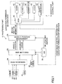
- FIG. 1 shows a configuration of a system mounted in a vehicle in one embodiment of the present invention.
- the system in the embodiment is provided with a positioning part 12 for measuring a position of the own vehicle, an assistance control part 14 for controlling running of the own vehicle or such.
- the assistance control part 14 carries out predetermined assistance control upon running of the own vehicle.
- the positioning part 12 has a GPS (Global Positioning System) receiver 16, a direction sensor 18, a G sensor 20 and a vehicle speed sensor 22.
- the GPS receiver 16 receives a GPS signal transmitted by a GPS satellite, and detects a longitude and a latitude of a position at which the own vehicle exists.
- the direction sensor 18 is a magnetic field sensor or a gyro sensor, and detects a yaw angle (direction) of the own vehicle.
- the G sensor 20 detects acceleration/deceleration of the own vehicle.
- the vehicle speed sensor 22 detects a speed of the own vehicle.
- Outputs of these receiver and sensors 16 through 22 are connected to a dead reckoning part 24 configured mainly by a microcomputer.
- the output signals of the receiver and sensors 16 through 22 are provided to the dead reckoning part 24 respectively.
- the dead reckoning part 24 detects the longitude and latitude of a current position of the own vehicle (initial coordinate) based on information from the GPS receiver 16, and also, detects a running condition such as a running direction of the own vehicle based on information from the sensors 18 through 22.
- the dead reckoning part 24 then produces a running track (estimated track) from the initial coordinate of the own vehicle.
- the positioning part 12 has a map matching part 26 configured mainly by a microcomputer connected with the dead reckoning part 24, and a map database 30 connected with the map matching part 26.
- the map database 30 is configured by a hard disk (HD), a DVD, or a CD mounted in the own vehicle or provided in a center.
- the map database 30 stores various map data such as link information of a road itself, a ground feature drawn or installed on the road, information concerning a traffic lane and so forth.
- the map data stored in the map database 30 includes information of a longitude and a latitude indicating the road, the lane shape such as a curvature, a slope, the number of lanes, a width of the lane, existence/absence of a corner, a type of the road, shape data, paint data and position data of each ground feature such as a pedestrian crossing, a stop line, a running direction arrow, a diamond sign indicating "a pedestrian crossing occurs", a speed limit sign, a turn prohibition sign, distance data among the respective ground features and so forth.
- the map database 30 is such that map data stored therein can be updated to a newest one through replacement of the disk, as a result of an updating condition being met, or so.
- the map matching part 26 To the map matching part 26, information of an estimated locus from the initial coordinate of the own vehicle position, produced for the purpose of map matching by the dead reckoning part 24 is provided.
- the map matching part 26 carries out map matching to correct the current position of the own vehicle onto a road link with the use of the link information of the road itself stored in the map database 30, each time when the information of the estimated locus is provided from the dead reckoning part 24.
- the map matching part 26 reads, from the map database 30, map data of a road scope estimated to be run by the own vehicle within a predetermined time or within a predetermined distance from then, from the current position of the own vehicle obtained from the map matching. Then, by determining whether or not a ground feature to be recognized is drawn or installed within the predetermined road scope from the current position, it is determined whether or not an image picked up by means of a back camera described later should be recognized. Simultaneously, characteristic data such as shape data or position data of the ground feature, shape data of the running lane and so forth are provided.
- the positioning part 12 has the back camera 32 connected with the map matching part 26.
- the back camera 32 is disposed on a vehicle rear bumper or such, and can pick up surroundings of a predetermined area including a road surface behind the vehicle from the position where it is disposed. The thus-picked-up image is provided to the map matching part 26 by the back camera 32.
- the map matching part 26 When determining that the picked-up image from the back camera 32 should be recognized, the map matching part 26 detects the above-mentioned ground feature drawn on the road, the running lane, and so forth, and also, grasps a mutual positional relationship of the ground feature and so forth with respect to the own vehicle, by carrying out image processing such as edge extraction on the picked-up image when the picked image is provided by the back camera 32.
- an area in which the ground feature and so forth occur may be previously determined based on the characteristic data such as the shape data or the position data of the ground feature and the running lane provided by the map database 30, and an area on which the image processing is to be carried out may be narrowed down electively from the entire picked-up image from the back camera 32, in a view point of improving the efficiency.
- the map matching part 26 calculates a position of the own lane corresponding to the own vehicle on the road which the own vehicle currently runs, based on the detection result for the running lane from the picked-up image of the back camera 32. Further, based on the extraction result for the ground feature, a mutual relationship (specifically, a distance from the own vehicle to the recognized ground feature) between the own vehicle and the recognized ground feature behind the own vehicle on the road is measured, and then, based on the measured result and the position data of the recognized ground feature stored in the map database 30, the position of the own vehicle is detected.
- the map matching part 26 carries out map matching to correct the current position of the own vehicle onto the road link stored in the map database 30, and also, when a ground feature is recognized from a picked-up image from the back camera 32, the map matching part 26 carries out map matching to correct the position of the own vehicle to a position which is based on the recognized ground feature of the recognition result. As will be described later, the map matching part 26 calculates correctness (i.e., a degree of self-confidence) which indicates accuracy of the current position of the own vehicle measured as a result of the map matching.
- correctness i.e., a degree of self-confidence
- the map matching part 26 compares with the map data stored in the map database 30 as a result of the position of the own vehicle being measured through the map matching, and, when it is thus determined that a target ground feature (for example, a stop line, an intersection, a curve approaching point or such) occurs which is a control target necessary to execute assistance control, in front in the running direction of the town vehicle, the map matching part 26 calculates, each time of the measurement after that, a distance along the center line of the running lane from the own vehicle to the target ground feature (referred to as an along-road remaining distance, hereinafter), based on a relationship between the thus-measured position of the own vehicle and the position of the target ground feature stored in the map database 30.
- a target ground feature for example, a stop line, an intersection, a curve approaching point or such
- the positioning part 12 has a vehicle position management part 36 connected with the map matching part 26.
- a link ID or a link coordinate of the current position of the own vehicle obtained as a result of map matching calculated by the map matching part 26, information of the degree of self-confidence indicating position accuracy thereof, information of the running lane on which the own vehicle currently runs, information of the along-road remaining distance from the own vehicle and the target ground feature, are provided, together with information of time at which the information is obtained.
- updating history information such as an elapsed time from updating, an updating condition and so forth for map data in the map database 30 is provided.
- the vehicle positron management part 36 Based on the information thus provided from the map matching part 26, the vehicle positron management part 36 detects the measured current position of the own vehicle and the along-road remaining distance to the target ground feature, and also detects an error in accuracy indicating the degree of self-confidence for the measured current position of the own vehicle.
- the information of the current position of the own vehicle and the along-road remaining distance thus detected by the vehicle position management part 36 are provided to, for example, a navigation unit which the own vehicle has, and, is displayed schematically on a map displayed on a display device thereof.
- the information of the current position coordinate of the own vehicle and the mutual relationship between the own vehicle and the target ground feature measured by the vehicle position management part 36 is provided to the assistance control part 14.
- the assistance control part 14 is provided with an electronic control unit (ECU) 40 configured mainly by a microcomputer, and carries out assistance control for a driver upon running of the own vehicle on a road, by the ECU 40.
- ECU electronice control unit
- the assistance control is carried out according to the position of the own vehicle.
- the assistance control may include halting control which is driving assistance control for halting the own vehicle at a ground feature on a road such as a stop line, railroad crossing or such, when braking operation is not made by the driver or braking operation is late; intersection control which is driving assistance control for preventing the own vehicle from crossing another vehicle which is estimated to cross an intersection which is a ground feature on a road; speed control such that the own vehicle approaches a curve (corner) which is a ground feature at an appropriate speed; guidance control for carrying out routing assistance with the use of voice with respect to a relative distance to a target ground feature, or such.
- the ECU 40 is connected with a brake actuator 42 for generating appropriate braking force in the own vehicle, a throttle actuator 44 for giving appropriate driving force to the own vehicle, shift actuator 46 for switching a transmission step of an automatic transmission, a steer actuator 48 for giving an appropriate steering angle to the own vehicle., and a buzzer alarm device 50 for sounding a buzzer, generating an alarm or generating a speaker output in the vehicle cabin.
- the ECU 40 provides appropriate driving commands to the respective actuators 42 through 50, based on the current position of the own vehicle and the mutual relationship between the own vehicle and the target ground feature measured and managed by the vehicle position movement part 36.
- the respective actuators 42 through 50 are driven according to the driving commands provided by the ECU 40.
- the dead reckoning part 24 of the positioning part 12 produces the estimated locus of the own vehicle from the initial coordinate based on the output of the respective receiver and sensors 16 through 22, at predetermined intervals, and provides it to the map matching part 26.
- the map matching part 26 compares the estimated locus of the own vehicle from the initial coordinate produced by the dead reckoning part 24 with the link information of the road stored in the map database 30 as map data, and thus, carries out map matching to correct the current position of the own vehicle onto the road link.
- the map matching part 26 reads, from the map database 30, map data of a road scope (all the lanes in a case of a plurality of lanes) estimated to be run by the own vehicle after that within a predetermined time or within a predetermined distance from the current position which is a result of the map matching, based on the result of the map matching. Then, it is determined whether or not a ground feature from the back camera 32 to be recognized occurs within the predetermined road scope, and it is determined whether or not the vehicle rear direction image with the back camera 32 should be recognized.
- the map matching part 26 When no ground feature to be recognized occurs within the predetermined road scope as a result of the above-mentioned determination, the map matching part 26 carries out nothing. On one hand, when a ground feature to be recognized occurs within the predetermined road scope, the map matching part 26 carries out image processing such as edge extraction from a picked-up image of the back camera 32, extracts the ground feature to be recognized from the picked-up image of the back camera 32 based on a result of the image processing, and also, detects a mutual positional relationship of the ground feature with respect to the own vehicle.
- image processing such as edge extraction from a picked-up image of the back camera 32, extracts the ground feature to be recognized from the picked-up image of the back camera 32 based on a result of the image processing, and also, detects a mutual positional relationship of the ground feature with respect to the own vehicle.
- the map matching part 26 accesses the map database 30, reads position data of the recognized ground feature, and also, based on the mutual positional relationship between the own vehicle and the recognized ground feature detected, the map matching part 26 detects a position of the own vehicle. In this case, map matching of the position of the own vehicle to a position according to the ground feature recognized from the camera picked-up image is carried out.
- the map matching part 26 When recognizing that the ground feature to be recognized occurs within the predetermined road scope, the map matching part 26 extracts the own lane in which the own vehicle runs from the camera picked-up image based on a result of the image processing of the back camera 32, and also, detects a mutual positional relationship of the own lane with respect to the own vehicle. At this time, further, the map matching part 26 accesses the map database 30, obtains a lane width of the running lane, the number of the lanes, a shape of the lane and so forth in the proximity to the own vehicle, and then, calculates a position of the own lane on the road on which the own vehicle currently runs.
- the map matching part 26 determines whether or not a target ground feature necessary to carry out assistance control occurs in the own lane in front of the running direction of the own vehicle.
- the map matching part 26 reads position data of the target ground feature from the map database 30, and after that, calculates an along-road remaining distance to the target ground feature from the own vehicle based on a relationship between the detected own vehicle position and the target ground feature. Then, the map matching part 26 outputs and provides information of the along-road remaining distance with information of the time attached thereto, to the vehicle position management part 36.
- the map matching part 26 calculates an accuracy error of the current position of the own vehicle measured at the time. Then, the map matching part 26 outputs and provides information of the measured current position of the own vehicle, together with information of the accuracy error, with information of the time attached thereto, to the vehicle position management part 36.
- the vehicle position management part 36 detects the current position of the own vehicle or the along-road remaining distance calculated by the matching part 26, and transmits information such as the vehicle position coordinate, the distance and time for the target ground feature, and so forth, to the ECU 40 of the assistance control part 14.
- the ECU 40 determines, for each set of assistance control, whether or not a control start condition is met which is determined for the control. When the control start condition is met, the ECU 40 starts the assistance control.
- automatic braking by the brake actuator 42 is started when the measured distance from the own vehicle to a stop line which is a target ground feature reaches 30 meters for example, and thus, the own vehicle is stopped on the stop line and the own vehicle is prevented from passing through the stop line.
- a voice guidance or such for informing the driver that the automatic braking is carried out may be provided before the automatic braking is started by the brake actuator 42.
- a speaker output is provided from the buzzer alarm device 50 at a time at which the measured distance from the own vehicle to a target ground feature such as an intersection becomes 100 meters for example, so that the driver is made to know that the target ground feature occurs in front.
- the GPS receiver 16, the bearing sensor 18, the G sensor 30, the vehicle speed sensor 22 and, the back camera 32 are used.
- an error occurs in the vehicle position measurement result since errors in detection parameters in the receiver and the various sensors 16 through 22, and the camera 32, errors included in various calculations upon measuring the position (for example, a rounding error for timing) occur.
- This positioning error is integrated along with a movement of the vehicle.
- the positioning part 12 carries out map matching such as to recognize the ground feature recognized from the picked-up image of the back camera 32, and to correct the position of the own vehicle.
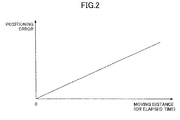
- the position accuracy in the current position of the own vehicle thus measured becomes the best one accordingly, and the error becomes the smallest ones. Accordingly, the positioning error becomes larger as the movement distance of the vehicle after the map matching based on the recognition of the ground feature from the camera picked-up image becomes longer (see FIG. 2 ).
- the own vehicle position is measured with the use of the map data stored in the map database 30 which can be updated.
- the positioning error may change according to the updating condition/updating scope or the elapsed time/movement distance from the previous updating of the map database 30, since the map data stored in the map database 30 may become different from the actual one due to repair of a road, new construction of a road or such.
- the positioning error becomes larger.
- the above-mentioned assistance control such as the stop control, intersection control, speed control, guidance control or such is such that, required accuracy in positioning the own vehicle position is different for each assistance control.
- positioning in high accuracy for example, within an error of 1 through 2 meters
- a target ground feature for example, an intersection to turn right
- low accuracy for example, an error of 40 through 50 meters
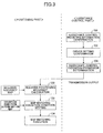
- FIG. 3 shows a flow chart of a control routine executed in the system of the present embodiment.
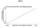
- FIG. 4 shows a map prescribing a relationship between required positioning accuracy and an execution frequency of map matching, in the assistance control used in the system of the present embodiment.
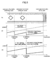
- FIG. 5 illustrates an advantage in the system of the present embodiment.
- the ECU 40 in the assistance control part 14 previously stores information (for example, the above-mentioned stop control or such, which may be different for each vehicle or each vehicle type) of the assistance control mounted in the own vehicle or information of assistance control which is not mounted in the own vehicle. Further, the vehicle driver may set as to whether or not to permit execution of the executable assistance control for each set thereof, with predetermined switching operation. To the ECU 40, information indicating whether or not execution of the executable assistance control is permitted according to an intention of the driver is thus input. The ECU 40 determines whether or not execution of each set of assistance control is permitted (Step 104) based on the thus-input information, when the information is input (Steps 100, 102).
- the information indicating whether not the assistance control is mounted in the own vehicle and whether or not execution of the assistance control is permitted is output and transmitted to the positioning part 12.
- information of accuracy in positioning required for appropriately executing the assistance control is previously stored as a required accuracy map. It is noted that the stored information of the required positioning accuracy may be one prescribing an error range in a specific unit of length (meter), or, one prescribing the error range with an accuracy level abstractly indicating a degree of a range of the length.
- the positioning accuracy may be such as, for the above-mentioned stop control, 2 meters or a level 1 indicating that the error is smallest, while, for the above-mentioned routing assistance control, 50 meters, or a level n indicating that the error is largest.
- the positioning part 12 identifies the assistance control mounted in the own vehicle based on the information of the assistance control mounted in the own vehicle and the information of execution permission, thus provided from the ECU 40 of the assistance control 14, and also, for each set of the thus-identified assistance control, calculates the required positioning accuracy with referring to the above-mentioned required accuracy map (Step 120). Then, based on the required positioning accuracy for each assistance control mounted in the own vehicle and, for which execution is permitted by intention of the driver, the positioning part 12 sets a execution condition for always ensuring the required positioning accuracy, which is a requirement for executing the above-mentioned map matching, i.e., a correction condition which is a requirement for correcting the own vehicle position (Step 122).
- the positioning part 12 previously stores an execution condition determination map prescribing a relationship between the required positioning accuracy and the map matching execution condition, and then, for setting the map matching execution condition, the positioning part 12 reads the execution condition determination map.
- the accuracy error in the positioning changes according to the execution frequency and/or the elapsed time/moving distance from the previous execution of map matching, and, as the execution frequency is smaller, or the elapsed time is longer, that is, the moving distance is longer, the accuracy error becomes larger. Therefore, in consideration of the change, the above-mentioned execution condition determination map is previously estimated experimentally and logically, and, is set so that, as the required positioning accuracy is higher, the map matching execution condition is more likely to be executed (for example, in FIG. 4 , the execution frequency is higher), and, also, as the required positioning accuracy is lower, the map matching execution condition is less likely to be executed (the execution frequency is lower).
- the positioning part 12 selects the positioning accuracy of 2 meters, and sets the execution frequency to execute the map matching corresponding to the positioning accuracy of 2 meters (for example, every time when the vehicle runs for 1 kilometer). Further, when the required positioning accuracy is on the order of 40 meters, and the assistance control is mounted in the own vehicle and execution thereof is permitted, the positioning part 12 selects the positioning accuracy of 40 meters, and sets the execution frequency to execute the map matching corresponding to the positioning accuracy of 40 meters (for example, every time when the vehicle runs for 20 kilometers).
- the highest one of the respective required positioning accuracies of the plurality of sets of assistance control is selected, and the execution frequency to execute the map matching is set corresponding to the highest positioning accuracy.
- the positioning accuracy of 2 meters corresponding to the stop control requiring the higher positioning accuracy of both sets of control is selected, and the map matching execution frequency corresponding to the positioning accuracy is set.
- the positioning part 12 When setting the map matching execution condition corresponding to the positioning accuracy as mentioned above upon system starting up, the positioning part 12 after that carries out map matching to correct the position of the own vehicle which is measured each time, according to the set execution condition to prevent the map matching execution condition from being not met (Step 124).
- the map matching part 26 reads from the map database 30 map data of a road scope estimated to run within a predetermined time or within a predetermined distance from the current position based on a result of the map matching, and determines whether or not a ground feature to be recognized by the own vehicle stored in the map data within the predetermined road scope occurs.
- image processing is carried out on a picked-up image behind the vehicle provided by the back camera 32, the ground feature to be recognized is thus recognized from the picked-up image, and thus, map matching is carried out to correct the own vehicle position to a position according to the ground feature recognized.
- the map data within the road scope estimated to run by the own vehicle from then within s distance or a time corresponding to the map matching execution condition (for example, the execution frequency) set as mentioned above is read from the map database 30, and a ground feature which is furthest spatially or temporally is selected wherefrom. Then, until the own vehicle approaches the thus-selected ground feature within a predetermined scope, image recognition from a picked-up image behind the vehicle from the back camera 32 is not carried out, and correction of the own vehicle positron based on a recognized ground feature is not carried out even when a ground feature stored in the map data occurs before the above-mentioned selected ground feature.
- the map matching execution condition for example, the execution frequency
- map matching is carried out in the same manner according to the set map matching execution condition.
- the assistance control which is actually mounted in the own vehicle and execution of which is permitted is identified, then, the positioning accuracy required for appropriately carrying out the assistance control is obtained, and the map matching execution condition for always ensuring the required positioning accuracy can be set.
- the map matching execution condition for always ensuring the required positioning accuracy can be set.
- the map matching execution condition to be set can be changed according to the assistance control, specifically, according to the positioning accuracy required for the assistance control. Then, map matching to correct the own vehicle position to a position based on a recognized ground feature can be carried out according to the map matching execution condition set according to the assistance control which is actually mounted in the own vehicle and execution of which is permitted,
- map matching to correct the own vehicle position based on a recognized ground feature is carried out relatively frequently when the positioning accuracy required for the assistance control which is mounted in the own vehicle and execution of which is permitted is relatively high as shown in FIG. 5 (B) . Further, map matching to correct the own vehicle position based on a recognized ground feature is carried out not so frequently when the positioning accuracy required for the assistance control which is mounted in the own vehicle and execution of which is permitted is relatively low as shown in FIG. 5 (C) . In any case, map matching to correct the own vehicle position is executed before the actual positioning accuracy error exceeds the required positioning accuracy.
- the positioning part 12 corresponds to vehicle positioning information updating system claimed
- the assistance control part 14 corresponds to 'assistance control unit' claimed
- the positioning accuracy required for appropriately carrying out each assistance control corresponds to 'characteristics' or 'level' claimed
- the own vehicle position obtained from map matching corresponds to positioning information' claimed
- the execution condition map prescribing the relationship between the positioning accuracy required for the assistance control and the map matching execution condition corresponds to 'map' claimed
- the map matching execution frequency corresponds to 'updating condition' and 'frequency of executing the updating' claimed
- the information indicating whether or not the assistance control is mounted and the information of whether or not execution of the assistance control is permitted corresponds to 'updating condition information' claimed.
- 'updating condition setting means' claimed is achieved as a result of the positioning part 12 carrying out Step 122 in the routing shown in Fig. 3
- 'updating executing means' claimed is achieved as a result of the positioning part 12 carrying out processing of Step 124
- 'outputting means' claimed is achieved as a result of the assistance control part 14 outputting and transmitting a processing result of Step 104 to the positioning part 12.
- the system in the embodiment mentioned above calculates the positioning accuracy required for the assistance control mounted in the own vehicle and execution of which is permitted, then, the map execution condition of map matching to correct the own vehicle position to a position based on a recognized ground feature is set in such a manner that the required positioning accuracy is always ensured.
- the present invention is not limited thereto.
- An updating condition to update the map data stored by the map database 30 mounted in the own vehicle may be set in such a manner that the positioning accuracy required for the assistance control is ensured.
- the positioning part 12 previously stores a map prescribing a relationship between the required positioning accuracy and an updating condition for the map database 30, then, the map is referred to, and the updating condition for the map database 30 is set based on the required positioning accuracy of the assistance control.
- the above-mentioned map is set in such a manner that, as the required positioning accuracy is higher, the updating condition for the map database 30 is such that updating is morse likely to be carried out (for example, the updating frequency is higher), and as the required positioning accuracy is slower, the updating condition for the map database 30 is such that updating is less likely to be carried out (for example, the updating frequency is lover).
- updating of the map database 30 (for example, a map data delivery request to the center, an alarm output to the driver to urge the driver to update the map database 30, or such) is carried out according to the updating condition.
- updating of the map database 30 is carried out relatively frequently when the positioning accuracy required for the assistance control mounted in the own vehicle and execution of which is permitted is high, while, when the positioning accuracy is relatively low, the updating is carried out not so frequently.
- the updating can be carried out before the actual positioning accuracy error exceeds the error corresponding to the required positioning accuracy. Accordingly, it is possible to always maintain the positioning accuracy of the own vehicle position in a state appropriately according to the assistance control mounted in the own vehicle, and thereby, the assistance control can be carried out appropriately according to the own vehicle position.
- the required positioning accuracy is calculated for each set of assistance control mounted in the own vehicle and execution of which is permitted, the highest one of the required positioning accuracies thereof is selected so that the required positioning accuracies thereof are always ensured, and the map matching execution condition (actually, the execution frequency) is set.
- a ground feature for example, only a stop line or a diamond sign in front to recognize in the stop control, only an intersection for the routing assistance control, or such
- an updating scope in the map database 30 prescribed to correspond to the assistance control mounted in the own vehicle and execution of which is permitted may be set as the updating condition, and updating of the map database 30 may be carried out only on the updating scope.
- the stop control according to the own vehicle position can be appropriately carried out.
- the ground feature required when the assistance control is carried out correspond to 'characteristics' or 'level' claimed
- the map data stored in the map database 30 corresponds to 'positioning information' claimed
- the updating scope in which the map database 30 storing the map data is updated corresponds to 'updating condition' claimed.
- the execution condition for map matching to correct the own vehicle position to a position based on a recognized ground feature is set, and then, after the system is started up, map matching is carried out within a road scope, which is estimated to run by the own vehicle for the distance or time corresponding to the execution condition based on the initial coordinate of the own vehicle position actually detected.
- map matching may be carried out within a road scope on this side of the target ground feature by the distance or the time corresponding to the execution condition based on the target ground feature, and, the map matching is carried out in sequence, every the distance or the time, retroactively.
- map matching is carried out based on a recognized ground feature according to the execution condition on the basis of certain time, without calculating the actual positioning accuracy.
- the positioning accuracy in measuring the position of the own vehicle may be calculated actually, and then, map matching is carried out before the calculated positioning accuracy exceeds the required positioning accuracy which is the basis of the execution condition.
- map matching can be carried out before the actual positioning accuracy exceeds the error corresponding to the required positioning accuracy according to the set execution condition.
- the above-mentioned embodiment is the system in which the plurality of sets of assistance control are executed by the single assistance control part 14, and the single assistance control part 14 outputs and transmits to the positioning part 12 the information indicating whether or not the sets of assistance control are mounted in the own vehicle and whether or not execution of the assistance control is permitted.
- a system may be such that the assistance control part may be provided for each set of assistance control, and each assistance control part outputs and transmits to the positioning part 12 the information indicating whether or not the corresponding set of assistance control is mounted in the own vehicle and whether or not execution thereof is permitted.
- the single assistance control part 14 carries out the plurality of sets of assistance control
- information indicating whether or not each assistance control is mounted and information indicating whether or not execution of the assistance control is permitted is output to the positioning part 12, and the positioning part 12 calculates the required positioning accuracy for each set of assistance control mounted in the own vehicle and execution of which is permitted, then, the highest one of the respective requester positioning accuracies thereof is selected so that these required positioning accuracies are always ensured, and the execution condition for the map matching is set.
- the assistance control part 14 may store the above-mentioned required accuracy map, the assistance control pars 14 may calculate the required positioning accuracy for each set of assistance control mounted in the own vehicle and execution of which is permitted, then, may select the highest one of the respective requester positioning accuracies thereof so that these required positioning accuracies are always ensured, and may output and transmit information of the highest required positioning accuracy to the positioning part 12, and the positioning part 12 may set the execution condition for the map matching according to the highest positioning accuracy.
- the information of the required highest positioning accuracy output and transmitted to the positioning part 12 by the assistance control part 14 corresponds to 'updating condition information' claimed.
- the back camera 32 disposed at the rear part of the vehicle is used to recognize a ground feature, and map matching is carried out to correct the own vehicle position to a position based on the recognized ground feature.
- the recognition of a ground feature for carrying out map matching may be carried out based on a picked-up image of a camera disposed at a front part of the vehicle or information transmitted from an external infrastructure.
- the map database 30 is mounted in the vehicle.
- the map database may be provided in the center, and the vehicle may communicate with and access the center each time to read data stored in the map database.
Landscapes
- Engineering & Computer Science (AREA)
- Remote Sensing (AREA)
- Radar, Positioning & Navigation (AREA)
- Physics & Mathematics (AREA)
- General Physics & Mathematics (AREA)
- Automation & Control Theory (AREA)
- Mechanical Engineering (AREA)
- Life Sciences & Earth Sciences (AREA)
- Atmospheric Sciences (AREA)
- Transportation (AREA)
- Mathematical Physics (AREA)
- Chemical & Material Sciences (AREA)
- Combustion & Propulsion (AREA)
- Databases & Information Systems (AREA)
- Navigation (AREA)
- Traffic Control Systems (AREA)
- Instructional Devices (AREA)
Applications Claiming Priority (2)
| Application Number | Priority Date | Filing Date | Title |
|---|---|---|---|
| JP2006136934A JP4938351B2 (ja) | 2006-05-16 | 2006-05-16 | 車両用測位情報更新装置 |
| PCT/JP2007/059978 WO2007132859A1 (fr) | 2006-05-16 | 2007-05-15 | Dispositif de mise à jour d'informations de positionnement du véhicule |
Publications (4)
| Publication Number | Publication Date |
|---|---|
| EP2019287A1 true EP2019287A1 (fr) | 2009-01-28 |
| EP2019287A4 EP2019287A4 (fr) | 2012-04-25 |
| EP2019287B1 EP2019287B1 (fr) | 2016-11-16 |
| EP2019287B8 EP2019287B8 (fr) | 2017-03-29 |
Family
ID=38693948
Family Applications (1)
| Application Number | Title | Priority Date | Filing Date |
|---|---|---|---|
| EP07743413.2A Ceased EP2019287B8 (fr) | 2006-05-16 | 2007-05-15 | Dispositif de mise à jour d'informations de positionnement du véhicule |
Country Status (6)
| Country | Link |
|---|---|
| US (1) | US8140266B2 (fr) |
| EP (1) | EP2019287B8 (fr) |
| JP (1) | JP4938351B2 (fr) |
| KR (1) | KR20080037708A (fr) |
| CN (1) | CN101346602B (fr) |
| WO (1) | WO2007132859A1 (fr) |
Cited By (1)
| Publication number | Priority date | Publication date | Assignee | Title |
|---|---|---|---|---|
| WO2014095510A2 (fr) * | 2012-12-20 | 2014-06-26 | Continental Teves Ag & Co. Ohg | Procédé de détermination d'une position de référence en tant que position de départ pour un système de navigation inertielle |
Families Citing this family (39)
| Publication number | Priority date | Publication date | Assignee | Title |
|---|---|---|---|---|
| US10056008B1 (en) | 2006-06-20 | 2018-08-21 | Zonar Systems, Inc. | Using telematics data including position data and vehicle analytics to train drivers to improve efficiency of vehicle use |
| WO2009030521A1 (fr) * | 2007-08-29 | 2009-03-12 | Continental Teves Ag & Co. Ohg | Correction d'une position de véhicule au moyen de points marquants |
| JP4466718B2 (ja) * | 2007-11-01 | 2010-05-26 | トヨタ自動車株式会社 | 走行軌跡生成方法及び走行軌跡生成装置 |
| JP4466716B2 (ja) * | 2007-11-01 | 2010-05-26 | トヨタ自動車株式会社 | 走行軌跡生成方法及び走行軌跡生成装置 |
| DE102008012697A1 (de) * | 2007-12-12 | 2009-06-18 | Daimler Ag | Verfahren zum Betrieb eines Navigationssystems und Navigationssystem |
| EP2242993B1 (fr) * | 2008-02-15 | 2013-10-23 | Continental Teves AG & Co. oHG | Système embarqué de navigation et/ou d'aide à la conduite de véhicules |
| DE112009004342B4 (de) * | 2009-02-19 | 2012-12-13 | Toyota Jidosha K.K. | Mobilobjektpositionserfassungsvorrichtung |
| RU2009108360A (ru) * | 2009-03-10 | 2010-09-20 | Михаил Юрьевич Воробьев (RU) | Способ измерения движения видеокамеры относительно поверхности и устройство для его осуществления |
| DE102010002093B4 (de) * | 2009-06-03 | 2024-03-14 | Continental Automotive Technologies GmbH | C2X-Kommunikation mit reduzierter Datenmenge |
| FR2947231B1 (fr) * | 2009-06-30 | 2013-03-29 | Valeo Vision | Procede pour determiner de maniere predictive des situations routieres d'un vehicule |
| JP5387277B2 (ja) * | 2009-08-07 | 2014-01-15 | アイシン・エィ・ダブリュ株式会社 | 走行支援で利用される情報の信頼度特定装置、方法およびプログラム |
| JP5249991B2 (ja) * | 2010-05-26 | 2013-07-31 | 株式会社エヌ・ティ・ティ・ドコモ | 測位装置及び方法 |
| JP5240248B2 (ja) * | 2010-06-29 | 2013-07-17 | トヨタ自動車株式会社 | 制御装置 |
| JP5706698B2 (ja) * | 2011-01-20 | 2015-04-22 | 本田技研工業株式会社 | 自動車用自動減速装置 |
| JP5303591B2 (ja) * | 2011-03-09 | 2013-10-02 | アイシン・エィ・ダブリュ株式会社 | 運転支援装置、運転支援方法及びコンピュータプログラム |
| KR101833217B1 (ko) * | 2011-12-07 | 2018-03-05 | 삼성전자주식회사 | 자기장 지도 기반 측위 시스템에서 이용되는 이동 단말 및 이를 이용한 위치 추정 방법 |
| KR101919366B1 (ko) * | 2011-12-22 | 2019-02-11 | 한국전자통신연구원 | 차량 내부 네트워크 및 영상 센서를 이용한 차량 위치 인식 장치 및 그 방법 |
| US10061745B2 (en) * | 2012-04-01 | 2018-08-28 | Zonar Sytems, Inc. | Method and apparatus for matching vehicle ECU programming to current vehicle operating conditions |
| CN104221068B (zh) * | 2012-04-12 | 2016-08-24 | 丰田自动车株式会社 | 驾驶辅助装置 |
| US9036865B2 (en) * | 2012-09-12 | 2015-05-19 | International Business Machines Corporation | Location determination for an object using visual data |
| WO2014045859A1 (fr) * | 2012-09-18 | 2014-03-27 | 株式会社村田製作所 | Chariot à main |
| DE102013012930A1 (de) * | 2013-08-02 | 2015-02-05 | Connaught Electronics Ltd. | Verfahren zum Bestimmen eines aktuellen Abstands und/oder einer aktuellen Geschwindigkeit eines Zielobjekts anhand eines Referenzpunkts in einem Kamerabild, Kamerasystem und Kraftfahrzeug |
| EP2950114B1 (fr) * | 2014-05-30 | 2020-03-04 | Honda Research Institute Europe GmbH | Procédé pour assister un conducteur lors de l'entraînement d'un véhicule, système d'assistance au conducteur, produit de programme logiciel informatique et véhicule |
| US10262213B2 (en) * | 2014-12-16 | 2019-04-16 | Here Global B.V. | Learning lanes from vehicle probes |
| JP6297482B2 (ja) * | 2014-12-26 | 2018-03-20 | 日立オートモティブシステムズ株式会社 | 情報処理装置 |
| BR112017027773B1 (pt) * | 2015-06-26 | 2022-06-21 | Nissan Motor Co., Ltd | Aparelho de determinação de posição de veículo e método de determinação de posição de veículo |
| US10248871B2 (en) * | 2016-03-24 | 2019-04-02 | Qualcomm Incorporated | Autonomous lane detection |
| CN108303103B (zh) * | 2017-02-07 | 2020-02-07 | 腾讯科技(深圳)有限公司 | 目标车道的确定方法和装置 |
| JP6637932B2 (ja) * | 2017-08-03 | 2020-01-29 | 株式会社Subaru | 車両用運転支援装置 |
| US10816354B2 (en) | 2017-08-22 | 2020-10-27 | Tusimple, Inc. | Verification module system and method for motion-based lane detection with multiple sensors |
| CN107633374A (zh) * | 2017-09-07 | 2018-01-26 | 安徽共生物流科技有限公司 | 一种可自我学习的车辆在途位置采集密度智能适应方法 |
| JP7127289B2 (ja) * | 2018-02-08 | 2022-08-30 | 株式会社デンソー | 運転支援装置、プログラム、運転支援方法 |
| US20230408264A1 (en) * | 2018-02-14 | 2023-12-21 | Tusimple, Inc. | Lane marking localization and fusion |
| US11009356B2 (en) * | 2018-02-14 | 2021-05-18 | Tusimple, Inc. | Lane marking localization and fusion |
| US11009365B2 (en) * | 2018-02-14 | 2021-05-18 | Tusimple, Inc. | Lane marking localization |
| CN109974722B (zh) * | 2019-04-12 | 2020-09-15 | 珠海市一微半导体有限公司 | 一种视觉机器人的地图更新控制方法及地图更新控制系统 |
| DE102020202964A1 (de) * | 2020-03-09 | 2021-09-09 | Continental Automotive Gmbh | Die Erfindung betrifft ein Verfahren zur Erhöhung der Sicherheit von Fahrfunktionen. |
| EP3893150A1 (fr) | 2020-04-09 | 2021-10-13 | Tusimple, Inc. | Techniques d'estimation de pose de caméra |
| KR20220029823A (ko) * | 2020-08-28 | 2022-03-10 | 주식회사 만도모빌리티솔루션즈 | 자율 주행 시스템 및 자율 주행 방법 |
Family Cites Families (32)
| Publication number | Priority date | Publication date | Assignee | Title |
|---|---|---|---|---|
| US3305671A (en) * | 1962-09-28 | 1967-02-21 | United Aircraft Corp | System for bounding the radius coordinate of an orbiting vehicle |
| US4359733A (en) * | 1980-09-23 | 1982-11-16 | Neill Gerard K O | Satellite-based vehicle position determining system |
| FR2695202B1 (fr) * | 1992-09-03 | 1994-11-10 | Aerospatiale | Système embarqué de navigation pour un engin aérien comportant un radar à visée latérale et à synthèse d'ouverture. |
| US5883739A (en) * | 1993-10-04 | 1999-03-16 | Honda Giken Kogyo Kabushiki Kaisha | Information display device for vehicle |
| US5826212A (en) * | 1994-10-25 | 1998-10-20 | Honda Giken Kogyo Kabushiki Kaisha | Current-position map and three dimensional guiding objects displaying device for vehicle |
| DE69635569T2 (de) * | 1995-04-25 | 2006-08-10 | Matsushita Electric Industrial Co., Ltd., Kadoma | Vorrichtung zum Bestimmen der lokalen Position eines Autos auf einer Strasse |
| KR100224326B1 (ko) * | 1995-12-26 | 1999-10-15 | 모리 하루오 | 차량용 네비게이션장치 |
| US5894323A (en) * | 1996-03-22 | 1999-04-13 | Tasc, Inc, | Airborne imaging system using global positioning system (GPS) and inertial measurement unit (IMU) data |
| JP3951328B2 (ja) | 1996-12-26 | 2007-08-01 | 株式会社エクォス・リサーチ | 車両制御装置 |
| JP3182509B2 (ja) * | 1997-04-28 | 2001-07-03 | 本田技研工業株式会社 | 自動変速機付き車両の自動操舵装置 |
| US6577334B1 (en) * | 1998-02-18 | 2003-06-10 | Kabushikikaisha Equos Research | Vehicle control |
| US6285317B1 (en) * | 1998-05-01 | 2001-09-04 | Lucent Technologies Inc. | Navigation system with three-dimensional display |
| US7366595B1 (en) * | 1999-06-25 | 2008-04-29 | Seiko Epson Corporation | Vehicle drive assist system |
| JP3907170B2 (ja) * | 1999-09-16 | 2007-04-18 | サーフ テクノロジー インコーポレイテッド | 物体の位置を追跡するためのナビゲーションシステムおよび方法 |
| JP4672190B2 (ja) * | 2001-04-26 | 2011-04-20 | 三菱電機株式会社 | 映像ナビゲーション装置 |
| FR2853978B1 (fr) * | 2003-04-16 | 2006-02-03 | Eurocopter France | Procede et dispositif de securisation du vol d'un aeronef en conditions de vol aux instruments hors infrastructures de vol aux instruments |
| US6704619B1 (en) * | 2003-05-24 | 2004-03-09 | American Gnc Corporation | Method and system for universal guidance and control of automated machines |
| KR100539834B1 (ko) * | 2003-06-30 | 2005-12-28 | 엘지전자 주식회사 | 차량 항법 유도 장치를 이용한 지도 버전 관리 방법 및시스템 |
| JP4225184B2 (ja) * | 2003-11-11 | 2009-02-18 | 日産自動車株式会社 | 地図信頼度算出装置 |
| JP4277717B2 (ja) * | 2004-03-17 | 2009-06-10 | 株式会社日立製作所 | 車両位置推定装置およびこれを用いた運転支援装置 |
| JP4581564B2 (ja) * | 2004-08-31 | 2010-11-17 | 株式会社デンソー | 地図表示装置 |
| US20060058953A1 (en) * | 2004-09-07 | 2006-03-16 | Cooper Clive W | System and method of wireless downloads of map and geographic based data to portable computing devices |
| JP2006136934A (ja) | 2004-11-15 | 2006-06-01 | Jfe Steel Kk | 電縫鋼管製造設備におけるフラッシュバット溶接方法 |
| US7720436B2 (en) * | 2006-01-09 | 2010-05-18 | Nokia Corporation | Displaying network objects in mobile devices based on geolocation |
| GB2422669A (en) * | 2005-01-31 | 2006-08-02 | Hewlett Packard Development Co | Article and a mobile networkable device for reading navigational data from an article |
| JP2006324836A (ja) * | 2005-05-18 | 2006-11-30 | Sony Corp | 画像処理装置および方法、並びにプログラム |
| JP4669331B2 (ja) * | 2005-06-24 | 2011-04-13 | アルパイン株式会社 | 車両用走行誘導装置及び車両用走行誘導装置の更新地図データ生成方法 |
| JP4735179B2 (ja) * | 2005-10-12 | 2011-07-27 | 株式会社デンソー | 車両制御装置 |
| JP4944551B2 (ja) * | 2006-09-26 | 2012-06-06 | 日立オートモティブシステムズ株式会社 | 走行制御装置、走行制御方法、および、走行制御プログラム |
| US20080249705A1 (en) * | 2007-04-04 | 2008-10-09 | Hitoki Matsuda | Realtime delivery system for updated map data |
| KR101541076B1 (ko) * | 2008-11-27 | 2015-07-31 | 삼성전자주식회사 | 지형지물 인식방법 |
| JP5387277B2 (ja) * | 2009-08-07 | 2014-01-15 | アイシン・エィ・ダブリュ株式会社 | 走行支援で利用される情報の信頼度特定装置、方法およびプログラム |
-
2006
- 2006-05-16 JP JP2006136934A patent/JP4938351B2/ja not_active Expired - Fee Related
-
2007
- 2007-05-15 CN CN200780000970XA patent/CN101346602B/zh not_active Expired - Fee Related
- 2007-05-15 KR KR1020087006005A patent/KR20080037708A/ko active Search and Examination
- 2007-05-15 US US12/066,907 patent/US8140266B2/en not_active Expired - Fee Related
- 2007-05-15 EP EP07743413.2A patent/EP2019287B8/fr not_active Ceased
- 2007-05-15 WO PCT/JP2007/059978 patent/WO2007132859A1/fr active Application Filing
Non-Patent Citations (2)
| Title |
|---|
| No further relevant documents disclosed * |
| See also references of WO2007132859A1 * |
Cited By (3)
| Publication number | Priority date | Publication date | Assignee | Title |
|---|---|---|---|---|
| WO2014095510A2 (fr) * | 2012-12-20 | 2014-06-26 | Continental Teves Ag & Co. Ohg | Procédé de détermination d'une position de référence en tant que position de départ pour un système de navigation inertielle |
| WO2014095510A3 (fr) * | 2012-12-20 | 2014-11-27 | Continental Teves Ag & Co. Ohg | Procédé de détermination d'une position de référence en tant que position de départ pour un système de navigation inertielle |
| US9658069B2 (en) | 2012-12-20 | 2017-05-23 | Continental Teves Ag & Co. Ohg | Method for determining a reference position as the starting position for an inertial navigation system |
Also Published As
| Publication number | Publication date |
|---|---|
| US20100082238A1 (en) | 2010-04-01 |
| EP2019287A4 (fr) | 2012-04-25 |
| CN101346602A (zh) | 2009-01-14 |
| EP2019287B1 (fr) | 2016-11-16 |
| EP2019287B8 (fr) | 2017-03-29 |
| JP2007309699A (ja) | 2007-11-29 |
| CN101346602B (zh) | 2012-05-30 |
| WO2007132859A1 (fr) | 2007-11-22 |
| KR20080037708A (ko) | 2008-04-30 |
| US8140266B2 (en) | 2012-03-20 |
| JP4938351B2 (ja) | 2012-05-23 |
Similar Documents
| Publication | Publication Date | Title |
|---|---|---|
| EP2019287B1 (fr) | Dispositif de mise à jour d'informations de positionnement du véhicule | |
| EP2019382B1 (fr) | Dispositif de commande de support | |
| JP4724043B2 (ja) | 対象物認識装置 | |
| EP2253936B1 (fr) | Dispositif de détermination de position actuelle et procédé de détermination de position actuelle | |
| JP4910510B2 (ja) | 制御用情報記憶装置及びプログラム | |
| US20180037223A1 (en) | Autonomous driving assistance system, autonomous driving assistance method, and computer program | |
| EP2269883A1 (fr) | Équipement de jugement de voie et système de navigation | |
| US11092442B2 (en) | Host vehicle position estimation device | |
| JP7047824B2 (ja) | 車両制御装置 | |
| EP2079066B1 (fr) | Appareil électronique embarqué et système de communication automobile | |
| KR101744781B1 (ko) | 도로의 형상 인식을 통한 예측 변속 제어 방법 | |
| US20120203452A1 (en) | Method for operating a motor vehicle and motor vehicle | |
| US20200234587A1 (en) | Systems and methods for driver assistance | |
| CN110869869A (zh) | 用于运行较高程度自动化的车辆(haf)、尤其是高度自动化的车辆的方法 | |
| JP7529526B2 (ja) | 車両制御装置及び車両制御方法 | |
| US11195349B2 (en) | External-world recognition system | |
| EP3550265B1 (fr) | Procédé de guidage routier et dispositif de guidage routier | |
| US20160139274A1 (en) | Information indication apparatus | |
| EP3835724B1 (fr) | Procédé d'estimation d'auto-localisation et dispositif d'estimation d'auto-localisation | |
| JP2012112691A (ja) | カーナビゲーション装置 | |
| JP7482613B2 (ja) | 交差点通過判定方法及び交差点通過判定装置 | |
| US20200256695A1 (en) | Systems and methods for driver assistance | |
| US20190107841A1 (en) | Driving assistance apparatus | |
| JP2021060766A (ja) | 車両遠隔操作システム |
Legal Events
| Date | Code | Title | Description |
|---|---|---|---|
| PUAI | Public reference made under article 153(3) epc to a published international application that has entered the european phase |
Free format text: ORIGINAL CODE: 0009012 |
|
| 17P | Request for examination filed |
Effective date: 20080314 |
|
| AK | Designated contracting states |
Kind code of ref document: A1 Designated state(s): AT BE BG CH CY CZ DE DK EE ES FI FR GB GR HU IE IS IT LI LT LU LV MC MT NL PL PT RO SE SI SK TR |
|
| AX | Request for extension of the european patent |
Extension state: AL BA HR MK RS |
|
| RIN1 | Information on inventor provided before grant (corrected) |
Inventor name: OKADA, KIYOKAZU Inventor name: NAKAMURA, MASAKI Inventor name: NAKAMURA, MOTOHIRO Inventor name: HASUNUMA, MAKOTO Inventor name: SUZUKI, HIDENOBU |
|
| DAX | Request for extension of the european patent (deleted) | ||
| RBV | Designated contracting states (corrected) |
Designated state(s): DE FR GB |
|
| A4 | Supplementary search report drawn up and despatched |
Effective date: 20120327 |
|
| RIC1 | Information provided on ipc code assigned before grant |
Ipc: G01C 21/32 20060101ALI20120321BHEP Ipc: B60R 16/02 20060101ALI20120321BHEP Ipc: B60R 21/00 20060101ALI20120321BHEP Ipc: G08G 1/0969 20060101ALI20120321BHEP Ipc: G08G 1/16 20060101ALI20120321BHEP Ipc: G01C 21/00 20060101AFI20120321BHEP |
|
| RAP1 | Party data changed (applicant data changed or rights of an application transferred) |
Owner name: TOYOTA JIDOSHA KABUSHIKI KAISHA Owner name: AISIN AW CO., LTD. |
|
| 17Q | First examination report despatched |
Effective date: 20151022 |
|
| GRAP | Despatch of communication of intention to grant a patent |
Free format text: ORIGINAL CODE: EPIDOSNIGR1 |
|
| RIC1 | Information provided on ipc code assigned before grant |
Ipc: G08G 1/16 20060101ALI20160523BHEP Ipc: B60W 40/072 20120101ALI20160523BHEP Ipc: G01C 21/00 20060101AFI20160523BHEP Ipc: B60W 50/00 20060101ALI20160523BHEP Ipc: B60R 21/00 20060101ALI20160523BHEP Ipc: G01C 21/32 20060101ALI20160523BHEP Ipc: B60R 16/02 20060101ALI20160523BHEP Ipc: B60W 10/18 20120101ALI20160523BHEP Ipc: G08G 1/0969 20060101ALI20160523BHEP Ipc: G08G 1/0967 20060101ALI20160523BHEP Ipc: B60W 40/076 20120101ALI20160523BHEP |
|
| INTG | Intention to grant announced |
Effective date: 20160609 |
|
| GRAS | Grant fee paid |
Free format text: ORIGINAL CODE: EPIDOSNIGR3 |
|
| GRAA | (expected) grant |
Free format text: ORIGINAL CODE: 0009210 |
|
| GRAT | Correction requested after decision to grant or after decision to maintain patent in amended form |
Free format text: ORIGINAL CODE: EPIDOSNCDEC |
|
| AK | Designated contracting states |
Kind code of ref document: B1 Designated state(s): DE FR GB |
|
| REG | Reference to a national code |
Ref country code: GB Ref legal event code: FG4D |
|
| RIN2 | Information on inventor provided after grant (corrected) |
Inventor name: SUZUKI, HIDENOBU Inventor name: NAKAMURA, MOTOHIRO Inventor name: NAKAMURA, MASAKI Inventor name: OKADA, KIYOKAZU Inventor name: HASUNUMA, MAKOTO |
|
| RIN2 | Information on inventor provided after grant (corrected) |
Inventor name: NAKAMURA, MASAKI Inventor name: HASUNUMA, MAKOTO Inventor name: OKADA, KIYOKAZU Inventor name: SUZUKI, HIDENOBU Inventor name: NAKAMURA, MOTOHIRO |
|
| REG | Reference to a national code |
Ref country code: DE Ref legal event code: R096 Ref document number: 602007048774 Country of ref document: DE |
|
| REG | Reference to a national code |
Ref country code: DE Ref legal event code: R096 Ref document number: 602007048774 Country of ref document: DE |
|
| GRAE | Information related to correction after decision to grant or after decision to maintain patent in amended form modified |
Free format text: ORIGINAL CODE: EPIDOSCCDEC |
|
| RIN2 | Information on inventor provided after grant (corrected) |
Inventor name: NAKAMURA, MOTOHIRO Inventor name: OKADA, KIYOKAZU Inventor name: NAKAMURA, MASAKI Inventor name: HASUNUMA, MAKOTO Inventor name: SUZUKI, HIDENOBU |
|
| REG | Reference to a national code |
Ref country code: FR Ref legal event code: PLFP Year of fee payment: 11 |
|
| REG | Reference to a national code |
Ref country code: DE Ref legal event code: R097 Ref document number: 602007048774 Country of ref document: DE |
|
| PLBE | No opposition filed within time limit |
Free format text: ORIGINAL CODE: 0009261 |
|
| STAA | Information on the status of an ep patent application or granted ep patent |
Free format text: STATUS: NO OPPOSITION FILED WITHIN TIME LIMIT |
|
| 26N | No opposition filed |
Effective date: 20170817 |
|
| REG | Reference to a national code |
Ref country code: FR Ref legal event code: PLFP Year of fee payment: 12 |
|
| PGFP | Annual fee paid to national office [announced via postgrant information from national office to epo] |
Ref country code: DE Payment date: 20190430 Year of fee payment: 13 |
|
| PGFP | Annual fee paid to national office [announced via postgrant information from national office to epo] |
Ref country code: FR Payment date: 20190410 Year of fee payment: 13 |
|
| PGFP | Annual fee paid to national office [announced via postgrant information from national office to epo] |
Ref country code: GB Payment date: 20190515 Year of fee payment: 13 |
|
| REG | Reference to a national code |
Ref country code: DE Ref legal event code: R119 Ref document number: 602007048774 Country of ref document: DE |
|
| GBPC | Gb: european patent ceased through non-payment of renewal fee |
Effective date: 20200515 |
|
| PG25 | Lapsed in a contracting state [announced via postgrant information from national office to epo] |
Ref country code: GB Free format text: LAPSE BECAUSE OF NON-PAYMENT OF DUE FEES Effective date: 20200515 Ref country code: FR Free format text: LAPSE BECAUSE OF NON-PAYMENT OF DUE FEES Effective date: 20200531 |
|
| PG25 | Lapsed in a contracting state [announced via postgrant information from national office to epo] |
Ref country code: DE Free format text: LAPSE BECAUSE OF NON-PAYMENT OF DUE FEES Effective date: 20201201 |