EP2018811B1 - Verfahren sowie Formungsstation zur Formgebung von Süsswarenschalen - Google Patents
Verfahren sowie Formungsstation zur Formgebung von Süsswarenschalen Download PDFInfo
- Publication number
- EP2018811B1 EP2018811B1 EP07014679A EP07014679A EP2018811B1 EP 2018811 B1 EP2018811 B1 EP 2018811B1 EP 07014679 A EP07014679 A EP 07014679A EP 07014679 A EP07014679 A EP 07014679A EP 2018811 B1 EP2018811 B1 EP 2018811B1
- Authority
- EP
- European Patent Office
- Prior art keywords
- confectionery
- confectionery mass
- mass
- mold
- mould
- Prior art date
- Legal status (The legal status is an assumption and is not a legal conclusion. Google has not performed a legal analysis and makes no representation as to the accuracy of the status listed.)
- Not-in-force
Links
Images


Classifications
-
- A—HUMAN NECESSITIES
- A23—FOODS OR FOODSTUFFS; TREATMENT THEREOF, NOT COVERED BY OTHER CLASSES
- A23G—COCOA; COCOA PRODUCTS, e.g. CHOCOLATE; SUBSTITUTES FOR COCOA OR COCOA PRODUCTS; CONFECTIONERY; CHEWING GUM; ICE-CREAM; PREPARATION THEREOF
- A23G1/00—Cocoa; Cocoa products, e.g. chocolate; Substitutes therefor
- A23G1/04—Apparatus specially adapted for manufacture or treatment of cocoa or cocoa products
- A23G1/20—Apparatus for moulding, cutting, or dispensing chocolate
- A23G1/21—Apparatus for moulding hollow products, open shells or other articles having cavities, e.g. open cavities
-
- A—HUMAN NECESSITIES
- A23—FOODS OR FOODSTUFFS; TREATMENT THEREOF, NOT COVERED BY OTHER CLASSES
- A23G—COCOA; COCOA PRODUCTS, e.g. CHOCOLATE; SUBSTITUTES FOR COCOA OR COCOA PRODUCTS; CONFECTIONERY; CHEWING GUM; ICE-CREAM; PREPARATION THEREOF
- A23G1/00—Cocoa; Cocoa products, e.g. chocolate; Substitutes therefor
- A23G1/0003—Processes of manufacture not relating to composition or compounding ingredients
- A23G1/005—Moulding, shaping, cutting, or dispensing chocolate
- A23G1/0053—Processes of shaping not covered elsewhere
- A23G1/0063—Processes in which the material is shaped at least partially in a mould, in the hollows of a surface, a drum, an endless band of by drop-by-drop casting or dispensing of the material on a surface, e.g. injection moulding, transfer moulding
-
- A—HUMAN NECESSITIES
- A23—FOODS OR FOODSTUFFS; TREATMENT THEREOF, NOT COVERED BY OTHER CLASSES
- A23G—COCOA; COCOA PRODUCTS, e.g. CHOCOLATE; SUBSTITUTES FOR COCOA OR COCOA PRODUCTS; CONFECTIONERY; CHEWING GUM; ICE-CREAM; PREPARATION THEREOF
- A23G1/00—Cocoa; Cocoa products, e.g. chocolate; Substitutes therefor
- A23G1/0003—Processes of manufacture not relating to composition or compounding ingredients
- A23G1/0076—Processes for moulding hollow products, open shells or other articles having cavities, e.g. open cavities
-
- A—HUMAN NECESSITIES
- A23—FOODS OR FOODSTUFFS; TREATMENT THEREOF, NOT COVERED BY OTHER CLASSES
- A23G—COCOA; COCOA PRODUCTS, e.g. CHOCOLATE; SUBSTITUTES FOR COCOA OR COCOA PRODUCTS; CONFECTIONERY; CHEWING GUM; ICE-CREAM; PREPARATION THEREOF
- A23G1/00—Cocoa; Cocoa products, e.g. chocolate; Substitutes therefor
- A23G1/04—Apparatus specially adapted for manufacture or treatment of cocoa or cocoa products
- A23G1/20—Apparatus for moulding, cutting, or dispensing chocolate
- A23G1/201—Apparatus not covered by groups A23G1/21 - A23G1/28
- A23G1/205—Apparatus in which the material is shaped at least partially in a mould, in the hollows of a surface, a drum, an endless band or by drop-by-drop casting or dispensing of the material on a surface, e.g. injection moulding, transfer moulding
-
- A—HUMAN NECESSITIES
- A23—FOODS OR FOODSTUFFS; TREATMENT THEREOF, NOT COVERED BY OTHER CLASSES
- A23G—COCOA; COCOA PRODUCTS, e.g. CHOCOLATE; SUBSTITUTES FOR COCOA OR COCOA PRODUCTS; CONFECTIONERY; CHEWING GUM; ICE-CREAM; PREPARATION THEREOF
- A23G3/00—Sweetmeats; Confectionery; Marzipan; Coated or filled products
- A23G3/0002—Processes of manufacture not relating to composition and compounding ingredients
- A23G3/0004—Processes specially adapted for manufacture or treatment of sweetmeats or confectionery
- A23G3/0019—Shaping of liquid, paste, powder; Manufacture of moulded articles, e.g. modelling, moulding, calendering
- A23G3/0025—Processes in which the material is shaped at least partially in a mould in the hollows of a surface, a drum, an endless band, or by a drop-by-drop casting or dispensing of the material on a surface, e.g. injection moulding, transfer moulding
- A23G3/0029—Moulding processes for hollow products, e.g. opened shell
-
- A—HUMAN NECESSITIES
- A23—FOODS OR FOODSTUFFS; TREATMENT THEREOF, NOT COVERED BY OTHER CLASSES
- A23G—COCOA; COCOA PRODUCTS, e.g. CHOCOLATE; SUBSTITUTES FOR COCOA OR COCOA PRODUCTS; CONFECTIONERY; CHEWING GUM; ICE-CREAM; PREPARATION THEREOF
- A23G3/00—Sweetmeats; Confectionery; Marzipan; Coated or filled products
- A23G3/02—Apparatus specially adapted for manufacture or treatment of sweetmeats or confectionery; Accessories therefor
- A23G3/0236—Shaping of liquid, paste, powder; Manufacture of moulded articles, e.g. modelling, moulding, calendering
- A23G3/0252—Apparatus in which the material is shaped at least partially in a mould, in the hollows of a surface, a drum, an endless band, or by a drop-by-drop casting or dispensing of the material on a surface, e.g. injection moulding, transfer moulding
- A23G3/0263—Moulding apparatus for hollow products, e.g. opened shell
Definitions
- the invention relates to a method for shaping confectionery trays by means of at least one stamping element and at least one recoverable mold, in which at least one mold cavity is provided, wherein at least the stamp element and the mold complete a stamping operation by means of a moving device, in which a separable mold is assembled, and wherein confectionery mass is filled in the mold cavity and preformed a cup-like confectionery body with an excess confectionery mass before carrying out the stamping process.
- the invention relates to a forming station for shaping confectionery trays comprising at least one stamping element and at least one recoverable mold having at least one mold cavity in a top of the mold, the stamping element and the mold to be movable towards each other from an initial position to an end position to produce a separable mold and wherein a preforming device is provided for preforming a cup-like confectionery body, so that a preformed confectionery body can be produced before the application of the stamping element.
- a method and an apparatus for producing confectionery trays is known from WO 02/089595 A1 known.
- the finished confectionery tray is formed with a stamp member, but before the stamping process, a degassing of the confectionery mass is performed. As a result, unwanted air bubbles contained in the confectionery mass are removed.
- Air bubbles should not be trapped in the wall of the finished shaped candy dish. Air bubbles are an undesirable effect when pouring confectionery mass. You may have formed before the casting process in the confectionery mass or caused by the casting process itself. From the general state of the art EP 0 589 820 A1 It is known to carry out the stamping process immediately after pouring the candy mass into the mold cavity. This leaves no time to remove air bubbles trapped in the confectionery mass. The air bubbles remain even in the finished confectionery bowl. A bubble affects the strength and makes the candy dish susceptible to damage. Where there is a bubble, the candy dish can be easily leaking. If the confectionery bowl is filled, there is a risk that the filling will leak out at the leaking place.
- each cavity deepens rotation around its own axis must be, the design effort is high. It must be provided a drive device with which the rotation is generated. The expense increases when a mold having multiple mold cavities, must be upgraded to put each mold cavity in rotation about its own axis.
- the invention is basically based on the same technical problem as in the case of WO 02/089595 A1 namely the most effective removal of air bubbles from the confectionery mass.
- WO 02/089595 A1 namely the most effective removal of air bubbles from the confectionery mass.
- bubble-free candy bowls There are largely desired bubble-free candy bowls. Therefore, a method and an apparatus for shaping confectionery trays is to be proposed, whereby the pre-distribution and preforming of the confectionery mass is simplified.
- this is achieved procedurally in that the casting mold is almost completely filled with confectionery mass and then turned over in order to preform the confectionery mass from the spatial position in which it has been filled, so that, by utilizing gravity from the inverted casting mold, so much confectionery mass is emptied, that at the top of the mold cavity at least such a quantity of partially crystallized confectionery mass is allowed to adhere as needed for the finished confectionery bowl that the evacuated mold is turned back, and that the finished inner contour of the confectionery bowl is formed by the stamping process.
- the proposed method of preforming results in a partially crystallized confectionery body adhering to the turned casting mold only by adhesion. In this way, a particularly large surface of the not yet completely solidified confectionery mass is achieved in the mold cavity and the removal of air bubbles very favored.
- the amount of confectionery mass that adheres in the mold cavity is thus preferably greater than that for the finished confectionery bowl required quantity.
- the partially crystallized confectionery mass is then formed into the exact shape.
- the turned mold can be placed in a spinning motion for the purpose of evacuating excess confectionery mass.
- the amount of adhering confectionery mass can be influenced by the trajectory of the centrifugal movement.
- the adhered amount of the confectionery mass is influenced by the frequency and optionally the amplitude of the centrifugal movement and by the temperature of the mold and the surrounding atmosphere.
- the spin movement can be performed in a plane on a circular path.
- a horizontal oscillating movement and optionally further a vertical oscillatory movement can be superimposed.
- an unbalance motor can be provided for generating each of these oscillatory movements.
- the acceleration forces that can be generated with the unbalance motor are variable by adjusting an imbalance mass.
- the confectionery mass contained in the mold cavity is preferably degassed before its partial evacuation.
- the excess portion of confectionery mass is forced out of the mold during the stamping process. This ensures that there is always enough confectionery for the complete filling of the confectionery bowl.
- the excess portion of the confectionery mass is conveniently conveyed away from the bowl edge of the confectionery bowl to the top of the mold surrounding the mold cavity, and the portion of confectionery mass conveyed from the forming cavity is separated from the confectionery mass present within the mold. Because there is no contact between the outwardly conveyed confectionery mass and the confectionery mass in the mold cavity, the excess portion of confectionery mass can be removed from the top of the mold without affecting the confectionery bowl. For example, the excess confectionery mass can simply be pushed over the top of the mold.
- the excess portion of the confectionery mass is conveyed away from the bowl edge of the confectionery bowl to the top of the mold cavity surrounding the mold cavity, but creating a connecting web between the extruded mass and the confectionery mass present within the mold.
- the advantage of this is that the solidifying excess confectionery mass is held by the connecting web when it is to be removed by a removal device from the top of the mold.
- the connecting web is designed so that it can tear off, but there is still some resistance to slippage of the confectionery mass, so that the confectionery mass can be better absorbed by a removal device because it is not pushed in front of the removal device. Otherwise, in a mold having a plurality of mold cavities, fragments of the solidifying confectionery mass may fall into another mold cavity as they are advanced in front of the excavator.
- the confectionery tray is shaped so that its shell edge receives an inwardly directed edge break.
- the edge refraction can be shaped like a chamfer or a rounding or have some other suitable geometry.
- the edge breakage favors the subsequent attachment of a lid made of confectionery mass, which is connected in the edge breaking with the confectionery tray, in which, for example, the areas to be joined are fused together.
- the part of the confectionery mass removed from the top of the casting mold can be returned to a plant intended for the production of the confectionery mass. It can be recrystallized and then recycled to the processing process.
- the portion of confectionery mass forced onto the top of the mold is preferably removed from the mold by rotating a doctor roll over the top of the mold, the confectionery mass adhering to the rotary doctor roll, and the adhering confectionery mass subsequently being released from the rotary doctor roll.
- the confectionery mass that sticks to the top of the mold by the process of evacuation may be removed before the stamping operation is performed.
- a forming station which is characterized in that the preforming device is provided with a turning device, that the casting mold by means of this turning device from the spatial position in which it is filled to turn so that a part of the Confectionery mass can be emptied by taking advantage of gravity from the turned mold, and that a return device is provided with which the evacuated mold is reversible.
- a confectionery tray is produced that is nearly free of air bubbles.
- the device technique used for this purpose is much simpler than in the generic state of the art, in which a paraboloidal surface of the confectionery mass produced by rotation must be generated in each individual mold cavity with high device overhead.
- a spinner with which the turned casting mold for the purpose of emptying excess confectionery mass in a centrifugal movement is displaceable.
- the amount of adhering confectionery mass can be influenced by the spin movement, for example, by changing their frequency.
- the spinner can have an eccentric drive whose eccentricity can be set, for example, in a range from 0 to 10 mm.
- the spin frequency can be set, for example, in a range from 0 to 100 hertz.
- the degassing device preferably has a degassing vibrator. With this vibrations can be initiated, for example by physical transfer into the mold.
- the stamping element may be provided with a severing device with which excess confectionery mass can be separated from the quantity of confectionery mass required for the finished confectionery bowl in the mold during the stamping process.
- the severing device simply has a separating edge provided on the stamp element.
- the stamping element is, in order to have a further benefit, provided with an edge forming surface, with the edges of the confectionery shell a directed towards the interior of the candy dish edge breakage can be generated.
- the edge breakage of the finished confectionery tray favors the subsequent attachment of a lid of confectionery mass, as already mentioned above.
- a removal device is provided, with the excess confectionery mass that has reached the top of the mold, from there is removable. Because confectionery material passes through the partial emptying during preforming on the flat top of the mold, it is advantageous if the confectionery mass can be removed again with the removal device. The same applies to confectionery mass, which is forced by the stamping process on the flat top of the mold. These can also be eliminated with the removal device.
- a removal device can be provided in front of and behind the stamping station. At least, however, a removal device is provided in the direction of passage behind the stamping station. This then removes both the preforming and the stamping process on the top of the mold arrived confectionery mass.
- the removal device expediently has a Ableckwalze.
- the Ableckwalze rotates in opposite directions over the top of the mold, the candy mass adheres to the rotating Ableckwalze and the adhering confectionery mass is then detached from the rotating Ableckwalze.
- the Ableckwalze is preferably tempered. Sweetener mass, which begins to solidify at the top of the mold, softens again as it contacts the roll surface. It adheres to the roll surface and is removed from the mold. At one of the mold facing away from a scraper is provided. The scraper is attached to the Ableckwalze and removes the confectionery mass from the Ableckwalze. This allows the Ableckwalze lick new confectionery mass from the top of the mold in the following revolution again.
- the temperature of the Ableckwalze example with warm water, which is passed through the interior of the Ableckwalze.
- Fig. 1 The drawing shows schematically a mold 1 is shown, which has a mold cavity 2.
- confectionery mass 3 In the mold cavity 2 confectionery mass 3 is filled, wherein the volume of the mold cavity 2 is almost completely filled.
- a casting mold such as that used for the industrial production of confectionery articles, is usually provided with a plurality of mold cavities.
- the illustrated mold 1 with the single mold cavity 2 serves to explain the principle of the invention.
- a degassing B shown which has a degassing b. With the degassing B a shaking movement is transmitted through the mold 1 in the confectionery mass 3 and in this way air bubbles to the surface of the molten candy mass 3 conveyed to obtain a possible bubble-free confectionery mass.
- Fig. 2 shows the mold 1 in a Vorformungs gifted V.
- the Vorformungs favorable V has a turning device W, with which the mold 1 has been turned.
- the mold cavity 2 with the degassed confectionery mass 3 contained therein points downwards, so that part of the confectionery mass 3 is emptied out of the mold cavity 2 by utilizing gravity.
- Another part of the confectionery mass 3 adheres by adhesion to the inner wall 2a, namely the surface of the mold cavity 2 adhere.
- the in FIG. 2 illustrated method step can be supported by a centrifugal movement, as indicated by the arrow 4 shown above the semolina mold 1.
- a spinner 5 is provided to transmit the centrifugal movement in the mold 1. If the confectionery mass 3 to be emptied is removed and only a remainder confectionery mass 3 adheres to the mold cavity, a further degassing takes place during the centrifugal movement. Any existing air bubbles have only a very short way to get to the surface of the adhering confectionery mass and escape. In this way, a very effective degassing is achieved.
- FIG. 3 also shows the preforming station V.
- the mold 1 is still in the position in which it was turned by the turning device W. It is according to Fig. 3 but already with a reverse turning device R in contact.
- Partially crystallized confectionery mass 3 adheres to the inner wall 2a of the mold cavity 2.
- a surrounding the edge of the mold cavity 2 top 1a of the mold 1 is wetted with a layer of confectionery mass 3, which has passed during the emptying of the top 1a of the mold 1.
- the adhering to the inner wall 2a of the mold cavity 2 amount of confectionery mass 3 forms a preformed confectionery body 10.
- the confectionery body 10 has more confectionery mass 3, as is needed for the finished confectionery bowl.
- the casting mold 1 is subsequently turned back by means of the reversing device R into which in FIG. 4 shown location.
- FIG. 4 moreover shows a removal device 6 with a Ableckwalze 6a, by means of which on the upper side 1a of the mold 1 adhering confectionery mass 3 is removed.
- the Ableckwalze 6a is tempered so that they melt the solidifying on the mold 1 confectionery mass 3b again and can lick in the molten state.
- the transport direction 7 of the mold 1 is indicated.
- the rotational movement of the Ableckwalze 6a with an arrow 8 is shown.
- the Rotational movement 8 of the Ableckwalze 6a opposite to the transport direction 7 of the mold 1.
- the Ableckwalze 6a adheres confectionery mass 3, which is removed from the mold 1.
- a scraper 9 is employed on the Ableckwalze 6a.
- the scraper 9 removes the confectionery mass 3 from the roll surface 6b of the Ableckwalze 6a.
- the candy mass 3 thus received is returned to the processing process and fed to a casting machine.
- FIG. 5 shows the mold 1 according to FIG. 4 with a completely freed from confectionery mass 3 top 1a of the mold 1.
- the mold cavity 2 is the preformed confectionery body 10.
- a stamp member 11 is shown in the mold cavity 2 .
- the stamp member 11 and the mold 1 are located relative to each other in an initial position A for a stamping operation.
- the stamping element 11 has a cut-off edge 11a, with which excess confectionery mass 3 is conveyed out of the mold cavity and separated at the end of the stamping process from the confectionery mass 3 forming the confectionery tray.
- the relative end position E for punch element 11 and mold 1 is in FIG. 7 shown.
- the mold 1 and the stamping element 11 form a closed mold, which forms the finished contour of the outside and the inside of the candy dish S.
- the excess amount 3b of the confectionery mass 3 has been forced out of the mold and separated from the confectionery tray S.
- the top of the mold 1 has a flat smooth Surface so that the excess amount 3b does not adhere firmly and can be removed well.
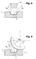
- FIG. 8 shows the finished confectionery tray S in the mold cavity 2 of the mold 1, wherein the punch member 11 and the mold 1 have been moved apart.
- the excess amount 3b of the confectionery mass 3 lies on the upper side 1a of the mold 1 and no longer has any contact with the confectionery tray S.
- the excess amount 3b of the confectionery mass 3 is taken up with a further Ableckwalze 6a and removed from the top 1a of the mold 1. At this time, the excess amount 3b of the confectionery mass 3 may easily slip on the smooth top surface of the casting mold when a thrust force is introduced from the skimming roller 6a.
- the Ableckwalze 6a has, moreover, the same structure and the same function as the Ableckwalze 6a according to FIG. 4 , It may be the same Ableckwalze 6a or there is an additional Ableckwalze 6a.
- the stamp member 11 has a different configuration than the stamp member according to Fig. 7 , Namely, the stamp member 11 is formed so that in the in Fig. 10 shown end position E on the shell edge of the confectionery shell S a gap T remains. In the gap T, a connecting web U of confectionery mass 3 is formed. The connecting web U connects the confectionery tray 3 with the surplus amount 3b of the confectionery mass 3 which has been forced out of the mold.
- Fig. 11 shows a partial enlargement according to XI in Fig. 10 , Therein, the gap T is shown and formed in the gap T connecting web U of confectionery mass 3.
- an edge forming surface 11b is provided on the stamp member 11, with the candy shell S is formed so that its shell edge receives an inwardly directed edge breakage K. how best in Fig. 11 to see.
- the edge breakage K favors the subsequent attachment a lid consisting of confectionery mass 3, which closes a previously introduced filling.
- the region of the edge refraction K can be reheated, for example, so that the surface of the edge refraction K has melted.
- the lid is then poured and fused with the bowl edge of the confectionery tray S.
- An equivalent edge forming surface is also in the embodiment according to the FIGS. 5 to 7 provided so that the finished confectionery tray S according to Fig. 7 also has at its edge of the bowl edge breakage, which is directed to the interior of the candy dish, and which favors the attachment of a lid of confectionery mass.
- Fig. 12 shows the candy dish S according to Fig. 10 ,
- the confectionery tray S and the connecting web U and the excess amount 3b are formed integrally with each other. Therefore, the excess amount 3b of the confectionery mass 3 on the smooth flat top 1a of the mold 1 can not easily slip off.
- a tempered Ableckwalze 6a the in Fig. 9 shown corresponds.
- the Ableckwalze 6a rotates in opposite directions over the top 1a of the mold 1. It exerts a thrust against the solidifying excess amount 3b of the candy mass 3 from.
- the excess amount 3b is supported by the connecting web U and prevented from easily slipping on the smooth top 1a of the mold 1. By this measure, it is better to push the Ableckwalze 6a against the supported excess amount 3b and transfer effective heat from the Ableckwalze 6a in the excess amount 3b of the confectionery mass 3, to melt and lick them.
- Fig. 13 shows a partial enlargement according to XIII in Fig. 12 , It is the connecting web U and the edge refraction K can be seen. In addition, the Ableckwalze 6a, which licks molten candy mass 3.
Description
- Die Erfindung betrifft ein Verfahren zur Formgebung von Süßwarenschalen mittels wenigstens einem Stempelelement und wenigstens einer förderbaren Gießform, in der wenigstens eine Formvertiefung vorgesehen ist, wobei zumindest das Stempelelement und die Gießform mittels einer Bewegungseinrichtung einen Stempelvorgang absolvieren, bei dem eine trennbare Form zusammengefügt wird, und wobei Süßwarenmasse in die Formvertiefung eingefüllt und vor Durchführung des Stempelvorgangs ein schalenartiger Süßwarenkörper mit einem Überschuss Süßwarenmasse vorgeformt wird.
- Außerdem betrifft die Erfindung eine Formungsstation zur Formgebung von Süßwarenschalen umfassend wenigstens ein Stempelelement und wenigstens eine förderbare Gießform mit wenigstens einer Formvertiefung in einer Oberseite der Gießform, wobei das Stempelelement und die Gießform zwecks Erzeugung einer trennbaren Form aus einer Ausgangsposition bis in eine Endposition aufeinander zu bewegbar sind, und wobei eine Vorformungseinrichtung zur Vorformung eines schalenartigen Süßwarenkörpers vorgesehen ist, so dass vor Anwendung des Stempelelements ein vorgeformter Süßwarenkörper herstellbar ist.
- Ein Verfahren und eine Vorrichtung zur Herstellung von Süßwarenschalen ist aus der
WO 02/089595 A1 - Luftblasen sollen nicht in der Wandung der fertig geformten Süßwarenschale eingeschlossen werden. Luftblasen sind ein unerwünschter Effekt beim Gießen der Süßwarenmasse. Sie können sich schon vor dem Gießvorgang in der Süßwarenmasse gebildet haben oder entstehen durch den Gießvorgang selbst. Aus dem allgemeinen Stand der Technik der
EP 0 589 820 A1 ist es bekannt, unmittelbar nach dem Gießen der Süßwarenmasse in die Formvertiefung den Stempelvorgang durchzuführen. Dadurch bleibt keine zeit, Luftblasen zu entfernen, die in der Süßwarenmasse eingeschlossen sind. Die Luftblasen bleiben selbst in der fertigen Süßwarenschale enthalten. Eine Luftblase beeinträchtigt die Festigkeit und macht die Süßwarenschale anfällig für eine Beschädigung. Dort, wo sich eine Luftblase befindet, kann die Süßwarenschale leicht undicht werden. Falls die Süßwarenschale mit einer Füllung versehen wird, besteht Gefahr, dass die Füllung an der undichten Stelle austritt. - Nach der gattungsbildenden Lehre der
WO 02/089595 A1 - Da jede Formvertiefung in Rotation um ihre eigene Achse versetzt werden muss, ist der konstruktive Aufwand hoch. Es muss eine Antriebsvorrichtung vorgesehen sein, mit der die Rotation erzeugt wird. Der Aufwand erhöht sich, wenn eine Gießform, die mehrere Formvertiefungen aufweist, aufgerüstet werden muss, um jede einzelne Formvertiefung in Rotation um die eigene Achse zu versetzen.
- Der Erfindung liegt grundsätzlich das gleiche technische Problem zugrunde, wie im Falle der
WO 02/089595 A1 - Erfindungsgemäß wir dies verfahrenstechnisch dadurch gelöst, dass die Gießform nahezu vollständig mit Süßwarenmasse gefüllt und anschließend zwecks Vorformung der Süßwarenmasse aus derjenigen Raumlage, in der sie befüllt worden ist, so gewendet wird, dass unter Ausnutzung der Schwerkraft aus der gewendeten Gießform soviel Süßwarenmasse ausgeleert wird, dass an der Oberseite der Formvertiefung wenigstens eine solche Menge teilkristallisierter Süßwarenmasse anhaften gelassen wird, wie für die fertige Süßwarenschale benötigt dass die ausgeleerte Gießform zurückgewendet wird, und dass die fertige Innenkontur der Süßwarenschale durch den Stempelvorgang geformt wird.
- Durch die vorgeschlagene Methode der Vorformung entsteht ein teilkristallisierter Süßwarenkörper, der nur durch Adhäsion an der gewendeten Gießform anhaftet. Auf diese Weise wird eine besonders große Oberfläche der noch nicht vollständig erstarrten Süßwarenmasse in der Formvertiefung erreicht und die Entfernung von Luftblasen sehr begünstigt.
- Die Menge der Süßwarenmasse, die in der Formvertiefung anhaftet, ist also vorzugsweise größer als die für die fertige Süßwarenschale benötigte Menge.
- Mit dem anschließenden Stempelvorgang wird die teilkristallisierte Süßwarenmasse dann in die exakte Gestalt geformt.
- Die gewendete Gießform kann zwecks Ausleerung überschüssiger Süßwarenmasse in eine Schleuderbewegung versetzt werden.
- Die Menge der anhaftenden Süßwarenmasse ist beeinflussbar durch die Bewegungsbahn der Schleuderbewegung. Außerdem wird die anhaftende Menge der Süßwarenmasse beeinflusst durch die Frequenz und gegebenenfalls die Amplitude der Schleuderbewegung sowie durch die Temperatur der Gießform und der umgebenden Atmosphäre.
- Die Schleuderbewegung kann in einer Ebene auf einer Kreisbahn ausgeführt werden. Zusätzlich kann eine horizontale Schwingbewegung und gegebenenfalls des weiteren eine vertikale Schwingbewegung überlagert werden. Zur Erzeugung jeder dieser Schwingbewegungen kann beispielsweise ein Unwuchtmotor vorgesehen sein. Vorzugsweise sind die mit dem Unwuchtmotor erzeugbaren Beschleunigungskräfte durch Verstellung einer Unwuchtmasse variabel.
- Die in der Formvertiefung befindliche Süßwarenmasse wird vorzugsweise vor ihrer teilweisen Ausleerung entgast.
- Günstigerweise wird beim Stempelvorgang der überschüssige Teil der Süßwarenmasse aus der Form hinausgedrängt. So wird gewährleistet, dass für die vollständige Füllung der Süßwarenschale stets genügend Süßwarenmasse vorhanden ist.
- Der überschüssige Teil der Süßwarenmasse wird zweckmäßig von dem Schalenrand der Süßwarenschale weg bis auf die die Formvertiefung umgebende Oberseite der Gießform befördert und der aus der Formvertiefung beförderte Teil der Süßwarenmasse wird von der innerhalb der Form vorhandenen Süßwarenmasse getrennt. Weil kein Kontakt mehr zwischen der nach außen beförderten Süßwarenmasse und der Süßwarenmasse in der Formvertiefung besteht, kann der überschüssige Teil der Süßwarenmasse von der Oberseite der Gießform ohne Einfluss auf die Süßwarenschale beseitigt werden. Die überschüssige Süßwarenmasse kann beispielsweise einfach über die Oberseite der Gießform geschoben werden.
- Alternativ kann vorgesehen sein, dass der überschüssige Teil der Süßwarenmasse von dem Schalenrand der Süßwarenschale weg bis auf die die Formvertiefung umgebende Oberseite der Gießform befördert wird, wobei jedoch ein Verbindungssteg zwischen der hinausgedrängten und der innerhalb der Form vorhandenen Süßwarenmasse erzeugt wird. Vorteilhaft daran ist, dass die erstarrende überschüssige Süßwarenmasse durch den Verbindungssteg gehalten wird, wenn sie durch eine Abtragseinrichtung von der Oberseite der Gießform entfernt werden soll. Der Verbindungssteg ist so ausgebildet, dass er abreißen kann, jedoch noch einen gewissen Widerstand gegen Verrutschen der Süßwarenmasse vorhanden ist, so dass die Süßwarenmasse von einer Abtragseinrichtung besser aufgenommen werden kann, weil sie nicht vor der Abtragseinrichtung hergeschoben wird. Bei einer Gießform mit mehreren Formvertiefungen könnten andernfalls Bruchstücke der erstarrenden Süßwarenmasse in eine andere Formvertiefung hineinfallen, wenn sie vor der Abtragseinrichtung hergeschoben werden.
- Ein weiterer Nutzen wird darin gesehen, dass die Süßwarenschale so geformt wird, dass ihr Schalenrand eine nach innen gerichtete Kantenbrechung erhält. Die Kantenbrechung kann wie eine Fase oder eine Rundung gestaltet sein oder eine sonstige geeignete Geometrie aufweisen. Die Kantenbrechung begünstigt die spätere Anbringung eines Deckels aus Süßwarenmasse, der im Bereich der Kantenbrechung mit der Süßwarenschale verbunden wird, in dem beispielsweise die zu verbindenden Bereiche miteinander verschmolzen werden.
- Der von der Oberseite der Gießform beseitigte Teil der Süßwarenmasse kann in eine zur Herstellung der Süßwarenmasse vorgesehene Anlage zurückbefördert werden. Sie kann dekristallisiert und dann dem Verarbeitungsprozess erneut zugeführt werden.
- Der auf die Oberseite der Gießform gedrängte Teil der Süßwarenmasse wird vorzugsweise dadurch von der Gießform abgetragen, dass eine Ableckwalze über die Oberseite der Gießform rotiert, wobei die Süßwarenmasse an der rotierenden Ableckwalze haften bleibt und die anhaftende Süßwarenmasse anschließend von der rotierenden Ableckwalze abgelöst wird.
- Die Süßwarenmasse, die durch den Vorgang der Ausleerung an der Oberseite der Gießform haften bleibt, kann beseitigt werden bevor der Stempelvorgang ausgeführt wird.
- Das zugrundegelegte technische Problem wird außerdem durch eine Formungsstation gelöst, die dadurch gekennzeichnet ist, dass die Vorformungseinrichtung mit einer Wendeeinrichtung versehen ist, dass die Gießform mittels dieser Wendeeinrichtung aus derjenigen Raumlage, in der sie befüllbar ist, so zu wenden ist, dass ein Teil der Süßwarenmasse unter Ausnutzung der Schwerkraft aus der gewendeten Gießform ausleerbar ist, und dass eine Rückwendeeinrichtung vorgesehen ist, mit der die ausgeleerte Gießform zurückwendbar ist.
- Durch die Kombination der Stempeltechnik mit der Technik der Vorformung eines Süßwarenkörpers durch Anhaftung teilkristallisierter Süßwarenmasse in der Formvertiefung, wird eine Süßwarenschale erzeugt, die nahezu frei von Luftblasen ist. Die hierfür eingesetzte Vorrichtungstechnik ist wesentlich einfacher als beim gattungsbildenden Stand der Technik, bei dem in jeder einzelnen Formvertiefung mit hohem Vorrichtungsaufwand eine durch Rotation erzeugte paraboloidförmige Oberfläche der Süßwarenmasse erzeugt werden muss.
- Es kann eine Schleudereinrichtung vorgesehen sein, mit der die gewendete Gießform zwecks Ausleerung überschüssiger Süßwarenmasse in eine Schleuderbewegung versetzbar ist. Die Menge der anhaftenden Süßwarenmasse kann durch die Schleuderbewegung beeinflusst werden, indem beispielsweise deren Frequenz verändert wird. Die Schleudereinrichtung kann einen Exzenterantrieb aufweisen, dessen Exzentrizität beispielsweise in einem Bereich vom 0 bis 10 mm eingestellt werden kann. Die Schleuderfrequenz kann beispielsweise in einem Bereich vom 0 bis 100 Hertz eingestellt werden.
- Es kann eine Entgasungseinrichtung vorgesehen sein, mit der die in der Formvertiefung befindliche Süßwarenmasse vor der teilweisen Ausleerung entgasbar ist. Auf diese Weise werden Luftblasen vor der Vorformung entfernt, während sich die Süßwarenmasse noch im schmelzflüssigen Zustand befindet.
- Die Entgasungseinrichtung weist vorzugsweise einen Entgasungsrüttler auf. Mit diesem können Schwingungen, beispielsweise durch körperliche Übertragung in die Gießform eingeleitet werden.
- Das Stempelelement kann mit einer Abtrenneinrichtung versehen sein, mit der überschüssige Süßwarenmasse während des Stempelvorgangs von der für die fertige Süßwarenschale in der Form benötigten Menge der Süßwarenmasse abtrennbar ist.
- Die Abtrenneinrichtung weist einfacherweise eine an dem Stempelelement vorgesehene Abtrennkante auf.
- Das Stempelelement ist, um einen weiteren Nutzen zu haben, mit einer Kantenformungsfläche versehen, mit der am Schalenrand der Süßwarenschale eine zum Inneren der Süßwarenschale gerichtete Kantenbrechung erzeugbar ist. Die Kantenbrechung der fertigen Süßwarenschale begünstigt die spätere Anbringung eines Deckel aus Süßwarenmasse, wie bereits oben erwähnt.
- Einfacherweise ist in der Endposition von Stempelelement und
- Gießform zwischen dem Rand der Formvertiefung und der Kantenformungsfläche ein Spalt vorgesehen. Durch den Spalt kann bis zum Erreichen der Endposition von Stempelelement und Gießform während des Stempelvorgangs Süßwarenmasse aus der Form hinausgedrängt werden. In der Endposition formt der Spalt einen Verbindungssteg zwischen der fertig geformten Süßwarenschale und dem aus der Form gedrängten überschüssigen Teil der Süßwarenmasse.
- Weiterhin nutzbringend ist es, wenn eine Abtragseinrichtung vorgesehen ist, mit der überschüssige Süßwarenmasse, die auf die Oberseite der Gießform gelangt ist, von dort entfernbar ist. Weil während der Vorformung Süßwarenmasse durch das teilweise Ausleeren auf die flache Oberseite der Gießform gelangt, ist es günstig, wenn die Süßwarenmasse mit der Abtragseinrichtung wieder beseitigt werden kann. Dasselbe gilt für Süßwarenmasse, die durch den Stempelvorgang auf die flache Oberseite der Gießform gedrängt wird. Auch diese kann mit der Abtragseinrichtung beseitigt werden. In Durchlaufrichtung der Gießformen kann vor und hinter der Stempelstation eine Abtragseinrichtung vorgesehen sein. Zumindest ist jedoch in Durchlaufrichtung hinter der Stempelstation eine Abtragseinrichtung vorgesehen. Diese entfernt dann sowohl die während der Vorformung als auch die durch den Stempelvorgang auf die Oberseite der Gießform gelangte Süßwarenmasse.
- Die Abtragseinrichtung weist zweckmäßig eine Ableckwalze auf. Die Ableckwalze rotiert gegenläufig über die Oberseite der Gießform, wobei die Süßwarenmasse an der rotierenden Ableckwalze haften bleibt und die anhaftende Süßwarenmasse anschließend von der rotierenden Ableckwalze abgelöst wird.
- Die Ableckwalze ist vorzugsweise temperiert. Süßwarenmasse, die an der Oberseite der Gießform zu erstarren beginnt, wird wieder weich, wenn sie die Walzenoberfläche berührt. Sie haftet an der Walzenoberfläche an und wird von der Gießform entfernt. An einer der Gießform abgewandten Stelle ist ein Abstreicher vorgesehen. Der Abstreicher ist an die Ableckwalze angestellt und entfernt die Süßwarenmasse von der Ableckwalze. Dadurch kann die Ableckwalze bei der folgenden Umdrehung wieder neue Süßwarenmasse von der Oberseite der Gießform ablecken. Die Temperierung der Ableckwalze erfolgt beispielsweise mit warmem Wasser, das durch das Innere der Ableckwalze hindurchgeleitet wird.
- Nachfolgend ist die Erfindung beispielhaft erläutert und anhand der schematischen Zeichnung beschrieben. Es zeigen:
- Fig. 1
- eine Gießform, die eine Formvertiefung aufweist mit- eingefüllter Süßwarenmasse,
- Fig. 2
- eine Vorformungseinrichtung mit einer darin befind- lichen Gießform gemäß
Fig. 1 , die zwecks Ausleerung von Süßwarenmasse gewendet ist, - Fig. 3
- die Vorformungseinrichtung gemäß
Fig. 2 mit der Gießform gemäßFig. 2 im ausgeleerten Zustand mit anhaftender Süßwarenmasse, - Fig. 4
- die Gießform gemäß
Fig. 3 zurückgewendet und eine Ableckwalze an der Oberseite der Gießform, - Fig. 5
- die Gießform gemäß
Fig. 4 und ein Stempelelement, - Fig. 6
- das Stempelelement gemäß
Fig. 5 während des Stempel- vorgangs, - Fig. 7
- das Stempelelement gemäß
Fig. 5 in der Endposition mit fertig geformter Süßwarenschale, - Fig. 8
- die fertig geformte Süßwarenschale in der Formver- tiefung der Gießform,
- Fig. 9
- die Gießform gemäß
Fig. 8 mit fertiger Süßwarenscha- le und Ableckwalze an der Oberseite, - Fig. 10
- eine alternative Ausführung mit geändertem Stempel- element in der Endposition mit fertig geformter Süß- warenschale,
- Fig. 11
- ein vergrößerter Ausschnitt gemäß XI in
Fig. 10 , - Fig. 12
- die Süßwarenschale und Gießform gemäß
Fig. 11 mit Ableckwalze an der Oberseite der Gießform, - Fig. 13
- ein vergrößerter Ausschnitt gemäß XIII in
Fig. 12 . - In
Fig. 1 der Zeichnung ist schematisch eine Gießform 1 dargestellt, die eine Formvertiefung 2 aufweist. In der Formvertiefung 2 ist Süßwarenmasse 3 eingefüllt, wobei das Volumen der Formvertiefung 2 nahezu vollständig gefüllt ist. In der Praxis ist eine Gießform, wie sie für die industrielle Produktion von Süßwarenartikeln verwendet wird, in der Regel mit mehreren Formvertiefungen versehen. Die abgebildete Gießform 1 mit der einzelnen Formvertiefung 2 dient zur prinzipiellen Erläuterung der Erfindung. Weiterhin ist inFig. 1 eine Entgasungseinrichtung B dargestellt, die einen Entgasungsrüttler b aufweist. Mit der Entgasungseinrichtung B wird eine Rüttelbewegung über die Gießform 1 in die Süßwarenmasse 3 übertragen und auf diese Weise Luftblasen an die Oberfläche der schmelzflüssigen Süßwarenmasse 3 befördert, um eine möglicht luftblasenfreie Süßwarenmasse zu erhalten. -
Fig. 2 zeigt die Gießform 1 in einer vorformungseinrichtung V. Die vorformungseinrichtung V weist eine Wendeeinrichtung W auf, mit der die Gießform 1 gewendet worden ist. Die Formvertiefung 2 mit der darin enthaltenen entgasten Süßwarenmasse 3 weist nach unten, so dass ein Teil der Süßwarenmasse 3 unter Ausnutzung der Schwerkraft aus der Formvertiefung 2 ausgeleert wird. Ein anderer Teil der Süßwarenmasse 3 bleibt durch Adhäsion an der Innenwand 2a, nämlich der Oberfläche der Formvertiefung 2 haften. - Der in
Figur 2 dargestellte Verfahrensschritt kann durch eine Schleuderbewegung unterstützt werden, wie durch den über der Grießform 1 dargestellten Pfeil 4 angedeutet. Zur Übertragung der Schleuderbewegung in die Gießform 1 ist eine Schleudereinrichtung 5 vorgesehen. Wenn die auszuleerende Süßwarenmasse 3 entfernt ist und nur noch ein Rest Süßwarenmasse 3 an der Formvertiefung anhaftet, erfolgt während der Schleuderbewegung eine weitere Entgasung. Eventuell vorhandene Luftblasen haben nur noch einen sehr kurzen Weg, um an die Oberfläche der anhaftenden Süßwarenmasse zu gelangen und zu entweichen. Auf diese Weise wird eine sehr effektive Entgasung erreicht. -
Figur 3 zeigt ebenfalls die Vorformungsstation V. Die Gießform 1 befindet sich noch in der Position, in die sie von der Wendeeinrichtung W gewendet wurde. Sie ist gemäßFig. 3 jedoch schon mit einer Rückwendeeinrichtung R in Kontakt. An der Innenwand 2a der Formvertiefung 2 haftet teilkristallisierte Süßwarenmasse 3 an. Eine den Rand der Formvertiefung 2 umgebende Oberseite 1a der Gießform 1 ist mit einer Schicht Süßwarenmasse 3 benetzt, die während der Ausleerung an die Oberseite 1a der Gießform 1 gelangt ist. Die an der Innenwand 2a der Formvertiefung 2 anhaftende Menge der Süßwarenmasse 3 bildet einen vorgeformten Süßwarenkörper 10. Der Süßwarenkörper 10 weist mehr Süßwarenmasse 3 auf, als für die fertige Süßwarenschale benötigt wird. Die Gießform 1 wird mittels der Rückwendeeinrichtung R anschließend zurückgewendet, in die inFigur 4 gezeigte Lage. -
Figur 4 zeigt darüber hinaus eine Abtragseinrichtung 6 mit einer Ableckwalze 6a, mittels der die an der Oberseite 1a der Gießform 1 anhaftende Süßwarenmasse 3 entfernt wird. Die Ableckwalze 6a ist temperiert, damit sie die auf der Gießform 1 erstarrende Süßwarenmasse 3b wieder schmelzen und im geschmolzenen Zustand ablecken kann. Mit einem Pfeil ist die Transportrichtung 7 der Gießform 1 angedeutet. Auf der Ableckwalze 6a ist die Rotationsbewegung der Ableckwalze 6a mit einem Pfeil 8 dargestellt. An der Oberseite 1a der Gießform 1 erfolgt die Rotationsbewegung 8 der Ableckwalze 6a gegenläufig zur Transportrichtung 7 der Gießform 1. An der Ableckwalze 6a haftet Süßwarenmasse 3 an, die von der Gießform 1 entfernt wird. An einer der Oberseite 1a der Gießform 1 abgewandten Stelle ist ein Abstreicher 9 an die Ableckwalze 6a angestellt. Der Abstreicher 9 entfernt die Süßwarenmasse 3 von der Walzenoberfläche 6b der Ableckwalze 6a. Die so aufgenommene Süßwarenmasse 3 wird in den Verarbeitungsprozess zurückgeführt und einer Gießmaschine zugeleitet. -
Figur 5 zeigt die Gießform 1 gemäßFigur 4 mit einer vollständig von Süßwarenmasse 3 befreiten Oberseite 1a der Gießform 1. In der Formvertiefung 2 befindet sich der vorgeformte Süßwarenkörper 10. Außerdem ist ein Stempelelement 11 dargestellt. Das Stempelelement 11 und die Gießform 1 befinden sich relativ zueinander in einer Ausgangsposition A für einen Stempelvorgang. Das Stempelelement 11 weist eine Abtrennkante 11a auf, mit der überschüssige Süßwarenmasse 3 aus der Formvertiefung herausbefördert und am Ende des Stempelvorgangs abgetrennt wird von der die Süßwarenschale bildenden Süßwarenmasse 3. - In
Figur 6 sind das Stempelelement 11 und die Gießform (1) ein Stück weit aufeinander zu bewegt. Die Formung der Süßwarenschale ist im Gange, jedoch noch nicht abgeschlossen. Eine Überschussmenge 3b der Süßwarenmasse 3 ist an der Abtrennkante 11a des Stempelelements 11 vorbei am Rand der Formvertiefung 2 aus der Form gedrängt worden und liegt auf der flachen Oberseite 1a der Gießform 1. - Die relative Endposition E für Stempelelement 11 und Gießform 1 ist in
Figur 7 dargestellt. Die Gießform 1 und das Stempelelement 11 bilden eine geschlossene Form, welche die fertige Kontur der Außenseite und der Innenseite der Süßwarenschale S formt. Die Überschussmenge 3b der Süßwarenmasse 3 ist aus der Form hinaus gedrängt und abgetrennt worden von der Süßwarenschale S. Die Oberseite der Gießform 1 weist eine flache glatte Oberfläche auf, damit die Überschussmenge 3b nicht fest anhaften und gut entfernt werden kann. -
Figur 8 zeigt die fertige Süßwarenschale S in der Formvertiefung 2 der Gießform 1, wobei das Stempelelement 11 und die Gießform 1 auseinander bewegt worden sind. Die Überschussmenge 3b der Süßwarenmasse 3 liegt auf der Oberseite 1a der Gießform 1 und hat keinen Kontakt mehr zur Süßwarenschale S. - Gemäß
Figur 9 wird die Überschussmenge 3b der Süßwarenmasse 3 mit einer weiteren Ableckwalze 6a aufgenommen und von der Oberseite 1a der Gießform 1 entfernt. Dabei kann die Überschussmenge 3b der Süßwarenmasse 3 auf der glatten Oberseite der Gießform leicht rutschen, wenn von der Ableckwalze 6a eine Schubkraft eingeleitet wird. - Die Ableckwalze 6a hat im Übrigen den gleichen Aufbau und die gleiche Funktion wie die Ableckwalze 6a gemäß
Figur 4 . Es kann sich um dieselbe Ableckwalze 6a handeln oder es ist eine zusätzliche Ableckwalze 6a vorgesehen. - In
Fig. 10 ist eine alternative Ausführung einer Formungsstation gezeigt, deren Stempelelement 11 eine andere Ausbildung aufweist, als das Stempelelement gemäßFig. 7 . Das Stempelelement 11 ist nämlich so ausgebildet, dass in der inFig. 10 gezeigten Endposition E am Schalenrand der Süßwarenschale S ein Spalt T verbleibt. In dem Spalt T ist ein Verbindungssteg U aus Süßwarenmasse 3 gebildet. Der Verbindungssteg U verbindet die Süßwarenschale 3 mit der aus der Form gedrängten Überschussmenge 3b der Süßwarenmasse 3.Fig. 11 zeigt eine ausschnittsweise Vergrößerung gemäß XI inFig. 10 . Darin ist der Spalt T dargestellt und der in dem Spalt T gebildete Verbindungssteg U aus Süßwarenmasse 3. Darüber hinaus ist an dem Stempelelement 11 eine Kantenformungsfläche 11b vorgesehen, mit der die Süßwarenschale S so geformt wird, dass ihr Schalenrand eine nach innen gerichtete Kantenbrechung K erhält, wie am besten inFig. 11 zu sehen. Die Kantenbrechung K begünstigt die spätere Anbringung eines aus Süßwarenmasse 3 bestehenden Deckels, der eine zuvor eingebrachte Füllung verschließt. Der Bereich der Kantenbrechung K kann beispielsweise erneut erwärmt werden, so dass die Oberfläche der Kantenbrechung K geschmolzen ist. Der Deckel wird dann dazu gegossen und verschmilzt mit dem Schalenrand der Süßwarenschale S. - Eine gleichwirkende Kantenformungsfläche ist auch in dem Ausführungsbeispiel gemäß der
Figuren 5 bis 7 vorgesehen, so dass die fertige Süßwarenschale S gemäßFig. 7 an ihrem Schalenrand ebenfalls eine Kantenbrechung aufweist, die zum Inneren der Süßwarenschale gerichtet ist, und welche die Anbringung eines Deckels aus Süßwarenmasse begünstigt. -
Fig. 12 zeigt die Süßwarenschale S gemäßFig. 10 . Die Süßwarenschale S sowie der Verbindungssteg U und die Überschussmenge 3b sind einstückig miteinander ausgebildet. Daher kann die Überschussmenge 3b der Süßwarenmasse 3 auf der glatten flachen Oberseite 1a der Gießform 1 nicht einfach wegrutschen. Es ist eine temperierte Ableckwalze 6a vorgesehen, die der inFig. 9 gezeigten entspricht. Die Ableckwalze 6a rotiert gegenläufig über die Oberseite 1a der Gießform 1. Sie übt dabei eine Schubkraft gegen die erstarrende Überschussmenge 3b der Süßwarenmasse 3 aus. Die Überschussmenge 3b ist durch den Verbindungssteg U abgestützt und daran gehindert, auf der glatten Oberseite 1a der Gießform 1 einfach weg zu rutschen. Durch diese Maßnahme gelingt es besser, die Ableckwalze 6a gegen die abgestützte Überschussmenge 3b zu schieben und effektiver Wärme von der Ableckwalze 6a in die Überschussmenge 3b der Süßwarenmasse 3 zu übertragen, um diese zu schmelzen und abzulecken. -
Fig. 13 zeigt eine ausschnittsweise Vergrößerung gemäß XIII inFig. 12 . Es ist der Verbindungssteg U und die Kantenbrechung K zu sehen. Außerdem ist die Ableckwalze 6a, welche geschmolzene Süßwarenmasse 3 ableckt. -
- 1
- Gießform
- 2
- Formvertiefung
- 2a
- Oberfläche/Innenwandung
- 3
- Süßwarenmasse
- 4
- Schleuderbewegung
- 5
- Schleudereinrichtung
- 6
- Abtragseinrichtung
- 6a
- Ableckwalze
- 6b
- Walzenoberfläche
- 7
- Transportrichtung (Gießform)
- 8
- Rotationsbewegung
- 9
- Abstreicher
- 10
- vorgeformter Süßwarenkörper
- 11
- Stempelelement
- 11a
- Abtrennkante
- 11b
- Kantenformungsfläche
- A
- Ausgangsposition
- B
- Entgasungseinrichtung
- b
- Entgasungsrüttler
- E
- Endposition
- K
- Kantenbrechung
- R
- Rückwendeeinrichtung
- S
- Süßwarenschale
- T
- Spalt
- U
- Verbindungssteg
- V
- Vorformungseinrichtung
- W
- Wendeeinrichtung
Claims (22)
- Verfahren zur Formgebung von Süßwarenschalen (S) mittels wenigstens einem Stempelelement (11) und wenigstens einer förderbaren Gießform (1), in der wenigstens eine Formvertiefung (2) vorgesehen ist, wobei zumindest das Stempelelement (11) und die Gießform (1) mittels einer Bewegungseinrichtung einen Stempelvorgang absolvieren, bei dem eine trennbare Form zusammengefügt wird, und wobei Süßwarenmasse (3) in die Formvertiefung (2) eingefüllt und vor Durchführung des Stempelvorgangs ein schalenartiger Süßwarenkörper (10) mit einem Überschuss Süßwarenmasse (3) vorgeformt wird, dadurch gekennzeichnet, dass die Gießform (1) nahezu vollständig mit Süßwarenmasse (3) gefüllt und anschließend zwecks Vorformung der Süßwarenmasse (3) aus derjenigen Raumlage, in der sie befüllt worden ist, so gewendet wird, dass unter Ausnutzung der Schwerkraft aus der gewendeten Gießform (1) soviel Süßwarenmasse (3) ausgeleert wird, dass an der Oberfläche (2a) der Formvertiefung (2) wenigstens eine solche Menge teilkristallisierter Süßwarenmasse (3) anhaften gelassen wird, wie für die fertige Süßwarenschale (S) benötigt, dass die ausgeleerte Gießform (1) zurückgewendet wird, und dass die fertige Innenkontur der Süßwarenschalen (S) durch den Stempelvorgang geformt wird.
- Verfahren nach Anspruch 1, dadurch gekennzeichnet, dass die gewendete Gießform (1) zwecks Ausleerung überschüssiger Süßwarenmasse (3) in eine Schleuderbewegung versetzt wird.
- Verfahren nach Anspruch 1 oder 2, dadurch gekennzeichnet, dass die Schleuderbewegung in einer Ebene auf einer Kreisbahn ausgeführt wird.
- Verfahren nach einem der Ansprüche 1 bis 3, dadurch gekennzeichnet, dass die in der Formvertiefung (2) befindliche Süßwarenmasse (3) vor ihrer Ausleerung entgast wird.
- Verfahren nach einem der Ansprüche 1 bis 4, dadurch gekennzeichnet, dass beim Stempelvorgang ein überschüssiger Teil der Süßwarenmasse (3) aus der Form hinausgedrängt wird.
- Verfahren nach Anspruch 5 dadurch gekennzeichnet, dass der überschüssige Teil der Süßwarenmasse (3) von dem Schalenrand der Süßwarenschale (S) weg bis auf die die Formvertiefung (2) umgebende Oberseite (1a) der Gießform (1) befördert wird, und dass der aus der Formvertiefung (2) beförderte Teil der Süßwarenmasse (3) getrennt wird von der innerhalb der Form vorhandenen Süßwarenmasse (3).
- Verfahren nach Anspruch 5 dadurch gekennzeichnet, dass der überschüssige Teil der Süßwarenmasse (3) von dem Schalenrand der Süßwarenschale (S) weg bis auf die die Formvertiefung (2) umgebende Oberseite (1a) der Gießform (1) befördert wird, und dass ein Verbindungssteg (U) zwischen der hinausgedrängten und der innerhalb der Form vorhandenen Süßwarenmasse (3) erzeugt wird.
- Verfahren nach einem der Ansprüche 1 bis 7 dadurch gekennzeichnet, dass die Süßwarenschale (S) so geformt wird, dass ihr Schalenrand eine nach innen gerichtete Kantenbrechung (K) erhält.
- Verfahren nach einem der Ansprüche 6 bis 8, dadurch gekennzeichnet , dass der überschüssige Teil der Süßwarenmasse (3) von der Oberseite (1a) der Gießform (1) beseitigt wird.
- Verfahren nach Anspruch 9, dadurch gekennzeichnet, dass der von der Oberseite (1a) der Gießform (1) beseitigte Teil der Süßwarenmasse (3) zurückbefördert wird in eine zur Herstellung der Süßwarenmasse vorgesehene Anlage.
- Verfahren nach Anspruch 9 oder 10, dadurch gekennzeichnet, dass der auf die Oberseite (1a) der Gießform (1) gedrängte Teil der Süßwarenmasse (3) abgetragen wird, indem eine Ableckwalze (6) über die Oberseite (1a) der Gießform (1) rotiert, dass die Süßwarenmasse (3) an der rotierenden Ableckwalze (6) haften bleibt, und dass die anhaftende Süßwarenmasse (3) von der rotierenden Ableckwalze (6) abgelöst wird.
- Verfahren nach einem der Ansprüche 9 bis 11, dadurch gekennzeichnet, dass Süßwarenmasse (3), die durch den Vorgang der Ausleerung an der Oberseite (1a) der Gießform (1) haften bleibt, beseitigt wird, bevor der Stempelvorgang ausgeführt wird.
- Formungsstation zur Formgebung von Süßwarenschalen (S) umfassend wenigstens ein Stempelelement (11) und wenigstens eine förderbare Gießform (1) mit einer Oberseite (1a), in der wenigstens eine Formvertiefung (2) vorgesehen ist, wobei das Stempelelement (11) und die Gießform (1) zwecks Erzeugung einer trennbaren Form aus einer Ausgangsposition (A) bis in eine Endposition (E) aufeinander zu bewegbar sind, und wobei eine Vorformungseinrichtung (V) zur Vorformung eines schalenartigen Süßwarenkörpers vorgesehen ist, so dass vor Anwendung des Stempelelements (11) ein vorgeformter Süßwarenkörper (10) herstellbar ist, dadurch gekennzeichnet, dass die Vorformungseinrichtung (V) mit einer Wendeeinrichtung (W) versehen ist, dass die Gießform (1) mit der Wendeeinrichtung (W) aus derjenigen Raumlage, in der sie befüllbar ist, so zu wenden ist, dass ein Teil der Süßwarenmasse (3) unter Ausnutzung der Schwerkraft aus der gewendeten Gießform (1) ausleerbar ist, und dass eine Rückwendeeinrichtung (R) vorgesehen ist, mit der die ausgeleerte Gießform (1) zurückwendbar ist.
- Formungsstation nach Anspruch 13, dadurch gekennzeichnen, dass eine Schleudereinrichtung (5) vorgesehen ist, mit der die gewendete Gießform (1) zwecks Ausleerung überschüssiger Süßwarenmasse (3) in eine Schleuderbewegung versetzbar ist.
- Formungsstation nach Anspruch 13 oder 14, dadurch gekennzeichnet, dass eine Entgasungseinrichtung (B) vorgesehen ist, mit der die in der Formvertiefung (2) befindliche Süßwarenmasse (3) vor der teilweisen Ausleerung entgasbar ist.
- Formungsstation nach Anspruch 15, dadurch gekennzeichnet, dass die Entgasungseinrichtung (B) einen Entgasungsrüttler (b) aufweist.
- Formungsstation nach einem der Ansprüche 13 bis 16, dadurch gekennzeichnet, dass das Stempelelement (11) mit einer Abtrenneinrichtung versehen ist, mit der überschüssige Süßwarenmasse (3) während des Stempelvorgangs abtrennbar ist von der für die fertige Süßwarenschale in der Form benötigten Menge der Süßwarenmasse (3).
- Formungsstation nach Anspruch 17, dadurch gekennzeichnet, dass die Abtrenneinrichtung eine an dem Stempelelement vorgesehene Abtrennkante (11a) aufweist.
- Formungsstation nach einem der Ansprüche 13 bis 18, dadurch gekennzeichnet, dass das Stempelelement (11) mit einer Kantenformungsfläche versehen ist, mit der am Schalenrand der Süßwarenschale eine zum Inneren der Süßwarenschale gerichtete Kantenbrechung erzeugbar ist.
- Formungsstation nach Anspruch 19, dadurch gekennzeichnet, dass in der Endposition (E) von Stempelelement (11) und Gießform (1) zwischen dem Rand der Formvertiefung (2) und der Kantenformungsfläche ein Spalt vorgesehen ist.
- Formungsstation nach einem der Ansprüche 13 bis 20, dadurch gekennzeichnet, dass eine Abtragseinrichtung (6) vorgesehen ist, mit der überschüssige Süßwarenmasse (3), die auf die Oberseite (1a) der Gießform (1) gelangt ist, von dort entfernbar ist.
- Formungsstation nach Anspruch 21, dadurch gekennzeichnet, dass die Abtragseinrichtung (6) eine Ableckwalze (6a) aufweist.
Priority Applications (4)
| Application Number | Priority Date | Filing Date | Title |
|---|---|---|---|
| EP07014679A EP2018811B1 (de) | 2007-07-26 | 2007-07-26 | Verfahren sowie Formungsstation zur Formgebung von Süsswarenschalen |
| AT07014679T ATE513476T1 (de) | 2007-07-26 | 2007-07-26 | Verfahren sowie formungsstation zur formgebung von süsswarenschalen |
| PL07014679T PL2018811T3 (pl) | 2007-07-26 | 2007-07-26 | Sposób oraz stanowisko formujące do formowania foremek cukierniczych |
| DK07014679.0T DK2018811T3 (da) | 2007-07-26 | 2007-07-26 | Indretning samt formningsstation til formgivning af konfektureskaller |
Applications Claiming Priority (1)
| Application Number | Priority Date | Filing Date | Title |
|---|---|---|---|
| EP07014679A EP2018811B1 (de) | 2007-07-26 | 2007-07-26 | Verfahren sowie Formungsstation zur Formgebung von Süsswarenschalen |
Publications (2)
| Publication Number | Publication Date |
|---|---|
| EP2018811A1 EP2018811A1 (de) | 2009-01-28 |
| EP2018811B1 true EP2018811B1 (de) | 2011-06-22 |
Family
ID=38720585
Family Applications (1)
| Application Number | Title | Priority Date | Filing Date |
|---|---|---|---|
| EP07014679A Not-in-force EP2018811B1 (de) | 2007-07-26 | 2007-07-26 | Verfahren sowie Formungsstation zur Formgebung von Süsswarenschalen |
Country Status (4)
| Country | Link |
|---|---|
| EP (1) | EP2018811B1 (de) |
| AT (1) | ATE513476T1 (de) |
| DK (1) | DK2018811T3 (de) |
| PL (1) | PL2018811T3 (de) |
Families Citing this family (10)
| Publication number | Priority date | Publication date | Assignee | Title |
|---|---|---|---|---|
| EP2543258B1 (de) * | 2011-07-06 | 2017-10-04 | Kraft Foods R & D, Inc. | Verfahren zur herstellung einer süsswarenschale |
| PL2543259T3 (pl) | 2011-07-06 | 2018-02-28 | Kraft Foods R & D, Inc. | Sposób wytwarzania skorupek wyrobów cukierniczych |
| EP2543260A1 (de) * | 2011-07-06 | 2013-01-09 | Kraft Foods R & D, Inc. | Verfahren zur Herstellung einer luftigen Süßwarenschale |
| CA2940834A1 (en) | 2014-02-27 | 2015-09-03 | The Hershey Company | Confectionery product and method of making |
| GB2525668A (en) * | 2014-05-02 | 2015-11-04 | Kraft Foods R & D Inc | Improvements in and relating to production of chocolate shells |
| CN106231914B (zh) * | 2014-05-06 | 2021-07-16 | 布勒股份公司 | 具有模制止挡件的压模板 |
| WO2018041884A2 (en) | 2016-08-30 | 2018-03-08 | Nestec Sa | Composition, process and use |
| JP6990665B2 (ja) | 2016-08-30 | 2022-01-12 | ソシエテ・デ・プロデュイ・ネスレ・エス・アー | エアレーションされたチョコ材料 |
| RU2734080C2 (ru) | 2016-08-30 | 2020-10-12 | Сосьете Де Продюи Нестле С.А. | Способ приготовления микропористого шоколадного материала |
| TR201802515A2 (tr) * | 2018-02-22 | 2018-03-21 | Elvan Gida Sanayii Ve Ticaret Anonim Sirketi | Meyve taneli̇ ve meyve şuruplu çi̇kolata üreti̇m yöntemi̇nde yeni̇ bi̇r geli̇şti̇rme |
Family Cites Families (9)
| Publication number | Priority date | Publication date | Assignee | Title |
|---|---|---|---|---|
| DE3411815A1 (de) * | 1984-03-30 | 1985-10-03 | Gebr. Bindler Maschinenfabrik GmbH & Co KG, 5275 Bergneustadt | Anlage zum herstellen von schokoladen-artikeln |
| DE3447245A1 (de) * | 1984-12-22 | 1986-06-26 | Winkler & Dünnebier, Maschinenfabrik und Eisengießerei GmbH & Co KG, 5450 Neuwied | Verfahren zum herstellen von hohlkoerper-schokoladenartikeln |
| DE4213293A1 (de) * | 1992-04-23 | 1993-10-28 | Winkler Duennebier Kg Masch | Verfahren und Vorrichtung zur Herstellung von Schokoladenartikeln |
| DK172603B1 (da) | 1992-09-23 | 1999-02-22 | Aasted Mikroverk Aps | Fremgangsmåde og anlæg til fremstilling af chokoladeartikler |
| EP0925720B1 (de) * | 1998-11-02 | 2001-09-12 | Aasted-Mikroverk Aps | Vorrichtung mit unabhängiger Aufhängung der Stempel zur Herstellung von Schalen aus fetthaltigen, schokoladeähnlichen Massen |
| DE10122548A1 (de) | 2001-05-09 | 2002-11-14 | Buehler Bindler Gmbh | Herstellung eines schalenartig geformten Verzehrgutes aus einer fetthaltigen Masse |
| EP1346643B1 (de) * | 2002-03-20 | 2006-05-03 | Aasted-Mikroverk Aps | Verfahren zur Herstellung von Schokoladenhülsen |
| DE10221524A1 (de) * | 2002-05-14 | 2003-12-04 | Kmb Produktions Ag Felben | Verfahren und Vorrichtung zum Herstellen von Verzehrgütern |
| GB2405827B (en) * | 2003-09-12 | 2007-01-31 | Mlom Ltd | Sweet manufacture |
-
2007
- 2007-07-26 EP EP07014679A patent/EP2018811B1/de not_active Not-in-force
- 2007-07-26 AT AT07014679T patent/ATE513476T1/de active
- 2007-07-26 PL PL07014679T patent/PL2018811T3/pl unknown
- 2007-07-26 DK DK07014679.0T patent/DK2018811T3/da active
Also Published As
| Publication number | Publication date |
|---|---|
| ATE513476T1 (de) | 2011-07-15 |
| DK2018811T3 (da) | 2011-10-03 |
| EP2018811A1 (de) | 2009-01-28 |
| PL2018811T3 (pl) | 2011-11-30 |
Similar Documents
| Publication | Publication Date | Title |
|---|---|---|
| EP2018811B1 (de) | Verfahren sowie Formungsstation zur Formgebung von Süsswarenschalen | |
| DE10152289B4 (de) | Verfahren und Vorrichtung zum Herstellen eines Formkörpers aus gekochter Zuckermasse in einer Form | |
| DE102008004088A1 (de) | Verfahren und Vorrichtung zum Herstellen von Behältern aus thermoplastischem Kunststoff sowie derart hergestellter Behälter | |
| DE60301947T2 (de) | Verwendung von Neuregulin-ß als Indikator und/oder Target | |
| EP2836347B1 (de) | Aus kunststoff gespritztes behältnis | |
| DE60305196T2 (de) | Verfahren zum rotationsformen eines werkstücks mit einer schicht aus thermoplastischem schaum | |
| DE69922360T2 (de) | Verfahren zur Formgebung von Lebensmitteln | |
| EP0566927B1 (de) | Verfahren und Vorrichtung zur Herstellung von Schokoladenartikeln | |
| DE102007028882B4 (de) | Extrusionsblasformmaschine sowie Verfahren zur Herstellung eines Kunststoffhohlkörpers | |
| EP1295531B1 (de) | Verfahren und Vorrichtung zum Formen einer Schale aus fett- und/oder zuckerhaltiger Masse in einer Form | |
| DE60201091T2 (de) | Vorrichtung zum Pressen von essbaren Artikeln | |
| DE3812805A1 (de) | Verfahren und vorrichtung zur herstellung von hohlkoerperfiguren aus schokolade | |
| DE1704078A1 (de) | Verfahren und Vorrichtung zur Herstellung von Rohlingen fuer die Blasverformung | |
| DE60224660T2 (de) | Vorrichtung und verfahren zum füllen eines trägerelements mit speiseeis | |
| CH680411A5 (en) | Moulding semi-solid aerated prod. e.g. chocolate - involves delivering prod. via vertical tube into open-bottomed recesses in heated horizontally moving mould | |
| DE60201604T2 (de) | Vorrichtung zum Formen essbarer Gegenstände | |
| EP1444901B1 (de) | Verfahren und Vorrichtung zur Herstellung schalenartiger Hohlkörper aus Süsswarenmasse | |
| EP2730172B1 (de) | Gießverfahren für Fruchtgummi | |
| EP3331370B1 (de) | Vorrichtung zum herstellen von verzehrgütern | |
| DE19652080C1 (de) | Verfahren zur Herstellung von Frucht- oder Schaumgummi-Bonbonwaren | |
| DE2136687C3 (de) | ||
| DE1955056C (de) | Vorrichtung zum Herstellen von hohlen Sußwarenteilen, insbesondere aus Hartzucker oder Bonbonmassen | |
| DE1963884A1 (de) | Verfahren zum kontinuierlichen Giessen und Verpacken von im Bearbeitungszustand deformierbarem oder fluessigem,haertbarem Material,Vorrichtung zur Durchfuehrung des Verfahrens sowie nach dem Verfahren erhaltenes Produkt | |
| DE2207597C2 (de) | Verfahren zur Herstellungeines Hohlkörpers, insbesondere aus Glas, Vorrichtung zur Durchführung des Verfahrens und Hohlkörper | |
| DE2418638C3 (de) | Verfahren und Vorrichtung zum Her stellen von einseitig geschlossenen Hohlkörpern aus thermoplastischem Kunststoff |
Legal Events
| Date | Code | Title | Description |
|---|---|---|---|
| PUAI | Public reference made under article 153(3) epc to a published international application that has entered the european phase |
Free format text: ORIGINAL CODE: 0009012 |
|
| AK | Designated contracting states |
Kind code of ref document: A1 Designated state(s): AT BE BG CH CY CZ DE DK EE ES FI FR GB GR HU IE IS IT LI LT LU LV MC MT NL PL PT RO SE SI SK TR |
|
| AX | Request for extension of the european patent |
Extension state: AL BA HR MK RS |
|
| 17P | Request for examination filed |
Effective date: 20090728 |
|
| AKX | Designation fees paid |
Designated state(s): AT BE BG CH CY CZ DE DK EE ES FI FR GB GR HU IE IS IT LI LT LU LV MC MT NL PL PT RO SE SI SK TR |
|
| GRAP | Despatch of communication of intention to grant a patent |
Free format text: ORIGINAL CODE: EPIDOSNIGR1 |
|
| GRAJ | Information related to disapproval of communication of intention to grant by the applicant or resumption of examination proceedings by the epo deleted |
Free format text: ORIGINAL CODE: EPIDOSDIGR1 |
|
| GRAP | Despatch of communication of intention to grant a patent |
Free format text: ORIGINAL CODE: EPIDOSNIGR1 |
|
| RIN1 | Information on inventor provided before grant (corrected) |
Inventor name: SCHEIDE, HELMUT Inventor name: RUNKEL, RAINER |
|
| GRAS | Grant fee paid |
Free format text: ORIGINAL CODE: EPIDOSNIGR3 |
|
| GRAA | (expected) grant |
Free format text: ORIGINAL CODE: 0009210 |
|
| AK | Designated contracting states |
Kind code of ref document: B1 Designated state(s): AT BE BG CH CY CZ DE DK EE ES FI FR GB GR HU IE IS IT LI LT LU LV MC MT NL PL PT RO SE SI SK TR |
|
| REG | Reference to a national code |
Ref country code: GB Ref legal event code: FG4D Free format text: NOT ENGLISH |
|
| REG | Reference to a national code |
Ref country code: CH Ref legal event code: EP |
|
| REG | Reference to a national code |
Ref country code: IE Ref legal event code: FG4D Free format text: LANGUAGE OF EP DOCUMENT: GERMAN |
|
| REG | Reference to a national code |
Ref country code: DE Ref legal event code: R096 Ref document number: 502007007484 Country of ref document: DE Effective date: 20110811 |
|
| REG | Reference to a national code |
Ref country code: CH Ref legal event code: NV Representative=s name: KATZAROV S.A. |
|
| REG | Reference to a national code |
Ref country code: DK Ref legal event code: T3 |
|
| REG | Reference to a national code |
Ref country code: NL Ref legal event code: VDEP Effective date: 20110622 |
|
| PG25 | Lapsed in a contracting state [announced via postgrant information from national office to epo] |
Ref country code: LT Free format text: LAPSE BECAUSE OF FAILURE TO SUBMIT A TRANSLATION OF THE DESCRIPTION OR TO PAY THE FEE WITHIN THE PRESCRIBED TIME-LIMIT Effective date: 20110622 Ref country code: SE Free format text: LAPSE BECAUSE OF FAILURE TO SUBMIT A TRANSLATION OF THE DESCRIPTION OR TO PAY THE FEE WITHIN THE PRESCRIBED TIME-LIMIT Effective date: 20110622 |
|
| PG25 | Lapsed in a contracting state [announced via postgrant information from national office to epo] |
Ref country code: FI Free format text: LAPSE BECAUSE OF FAILURE TO SUBMIT A TRANSLATION OF THE DESCRIPTION OR TO PAY THE FEE WITHIN THE PRESCRIBED TIME-LIMIT Effective date: 20110622 Ref country code: LV Free format text: LAPSE BECAUSE OF FAILURE TO SUBMIT A TRANSLATION OF THE DESCRIPTION OR TO PAY THE FEE WITHIN THE PRESCRIBED TIME-LIMIT Effective date: 20110622 Ref country code: SI Free format text: LAPSE BECAUSE OF FAILURE TO SUBMIT A TRANSLATION OF THE DESCRIPTION OR TO PAY THE FEE WITHIN THE PRESCRIBED TIME-LIMIT Effective date: 20110622 Ref country code: CY Free format text: LAPSE BECAUSE OF FAILURE TO SUBMIT A TRANSLATION OF THE DESCRIPTION OR TO PAY THE FEE WITHIN THE PRESCRIBED TIME-LIMIT Effective date: 20110622 Ref country code: GR Free format text: LAPSE BECAUSE OF FAILURE TO SUBMIT A TRANSLATION OF THE DESCRIPTION OR TO PAY THE FEE WITHIN THE PRESCRIBED TIME-LIMIT Effective date: 20110923 |
|
| REG | Reference to a national code |
Ref country code: PL Ref legal event code: T3 |
|
| PG25 | Lapsed in a contracting state [announced via postgrant information from national office to epo] |
Ref country code: MT Free format text: LAPSE BECAUSE OF FAILURE TO SUBMIT A TRANSLATION OF THE DESCRIPTION OR TO PAY THE FEE WITHIN THE PRESCRIBED TIME-LIMIT Effective date: 20110622 Ref country code: NL Free format text: LAPSE BECAUSE OF FAILURE TO SUBMIT A TRANSLATION OF THE DESCRIPTION OR TO PAY THE FEE WITHIN THE PRESCRIBED TIME-LIMIT Effective date: 20110622 |
|
| REG | Reference to a national code |
Ref country code: IE Ref legal event code: FD4D |
|
| BERE | Be: lapsed |
Owner name: WINKLER UND DUNNEBIER SUSSWARENMASCHINEN G.M.B.H. Effective date: 20110731 |
|
| PG25 | Lapsed in a contracting state [announced via postgrant information from national office to epo] |
Ref country code: EE Free format text: LAPSE BECAUSE OF FAILURE TO SUBMIT A TRANSLATION OF THE DESCRIPTION OR TO PAY THE FEE WITHIN THE PRESCRIBED TIME-LIMIT Effective date: 20110622 Ref country code: IE Free format text: LAPSE BECAUSE OF FAILURE TO SUBMIT A TRANSLATION OF THE DESCRIPTION OR TO PAY THE FEE WITHIN THE PRESCRIBED TIME-LIMIT Effective date: 20110622 Ref country code: IS Free format text: LAPSE BECAUSE OF FAILURE TO SUBMIT A TRANSLATION OF THE DESCRIPTION OR TO PAY THE FEE WITHIN THE PRESCRIBED TIME-LIMIT Effective date: 20111022 Ref country code: PT Free format text: LAPSE BECAUSE OF FAILURE TO SUBMIT A TRANSLATION OF THE DESCRIPTION OR TO PAY THE FEE WITHIN THE PRESCRIBED TIME-LIMIT Effective date: 20111024 Ref country code: CZ Free format text: LAPSE BECAUSE OF FAILURE TO SUBMIT A TRANSLATION OF THE DESCRIPTION OR TO PAY THE FEE WITHIN THE PRESCRIBED TIME-LIMIT Effective date: 20110622 |
|
| PG25 | Lapsed in a contracting state [announced via postgrant information from national office to epo] |
Ref country code: RO Free format text: LAPSE BECAUSE OF FAILURE TO SUBMIT A TRANSLATION OF THE DESCRIPTION OR TO PAY THE FEE WITHIN THE PRESCRIBED TIME-LIMIT Effective date: 20110622 Ref country code: MC Free format text: LAPSE BECAUSE OF NON-PAYMENT OF DUE FEES Effective date: 20110731 Ref country code: SK Free format text: LAPSE BECAUSE OF FAILURE TO SUBMIT A TRANSLATION OF THE DESCRIPTION OR TO PAY THE FEE WITHIN THE PRESCRIBED TIME-LIMIT Effective date: 20110622 |
|
| PLBE | No opposition filed within time limit |
Free format text: ORIGINAL CODE: 0009261 |
|
| STAA | Information on the status of an ep patent application or granted ep patent |
Free format text: STATUS: NO OPPOSITION FILED WITHIN TIME LIMIT |
|
| PG25 | Lapsed in a contracting state [announced via postgrant information from national office to epo] |
Ref country code: BE Free format text: LAPSE BECAUSE OF NON-PAYMENT OF DUE FEES Effective date: 20110731 |
|
| GBPC | Gb: european patent ceased through non-payment of renewal fee |
Effective date: 20110922 |
|
| 26N | No opposition filed |
Effective date: 20120323 |
|
| REG | Reference to a national code |
Ref country code: DE Ref legal event code: R097 Ref document number: 502007007484 Country of ref document: DE Effective date: 20120323 |
|
| PG25 | Lapsed in a contracting state [announced via postgrant information from national office to epo] |
Ref country code: GB Free format text: LAPSE BECAUSE OF NON-PAYMENT OF DUE FEES Effective date: 20110922 |
|
| PG25 | Lapsed in a contracting state [announced via postgrant information from national office to epo] |
Ref country code: ES Free format text: LAPSE BECAUSE OF FAILURE TO SUBMIT A TRANSLATION OF THE DESCRIPTION OR TO PAY THE FEE WITHIN THE PRESCRIBED TIME-LIMIT Effective date: 20111003 |
|
| PG25 | Lapsed in a contracting state [announced via postgrant information from national office to epo] |
Ref country code: LU Free format text: LAPSE BECAUSE OF NON-PAYMENT OF DUE FEES Effective date: 20110726 |
|
| PG25 | Lapsed in a contracting state [announced via postgrant information from national office to epo] |
Ref country code: BG Free format text: LAPSE BECAUSE OF FAILURE TO SUBMIT A TRANSLATION OF THE DESCRIPTION OR TO PAY THE FEE WITHIN THE PRESCRIBED TIME-LIMIT Effective date: 20110922 |
|
| REG | Reference to a national code |
Ref country code: AT Ref legal event code: MM01 Ref document number: 513476 Country of ref document: AT Kind code of ref document: T Effective date: 20120731 |
|
| PG25 | Lapsed in a contracting state [announced via postgrant information from national office to epo] |
Ref country code: TR Free format text: LAPSE BECAUSE OF FAILURE TO SUBMIT A TRANSLATION OF THE DESCRIPTION OR TO PAY THE FEE WITHIN THE PRESCRIBED TIME-LIMIT Effective date: 20110622 |
|
| PG25 | Lapsed in a contracting state [announced via postgrant information from national office to epo] |
Ref country code: AT Free format text: LAPSE BECAUSE OF NON-PAYMENT OF DUE FEES Effective date: 20120731 Ref country code: HU Free format text: LAPSE BECAUSE OF FAILURE TO SUBMIT A TRANSLATION OF THE DESCRIPTION OR TO PAY THE FEE WITHIN THE PRESCRIBED TIME-LIMIT Effective date: 20110622 |
|
| REG | Reference to a national code |
Ref country code: FR Ref legal event code: PLFP Year of fee payment: 9 |
|
| REG | Reference to a national code |
Ref country code: FR Ref legal event code: PLFP Year of fee payment: 10 |
|
| REG | Reference to a national code |
Ref country code: FR Ref legal event code: PLFP Year of fee payment: 11 |
|
| PGFP | Annual fee paid to national office [announced via postgrant information from national office to epo] |
Ref country code: FR Payment date: 20170720 Year of fee payment: 11 |
|
| PGFP | Annual fee paid to national office [announced via postgrant information from national office to epo] |
Ref country code: PL Payment date: 20170713 Year of fee payment: 11 |
|
| REG | Reference to a national code |
Ref country code: CH Ref legal event code: PCAR Free format text: NEW ADDRESS: AVENUE DES MORGINES 12, 1213 PETIT-LANCY (CH) |
|
| PGFP | Annual fee paid to national office [announced via postgrant information from national office to epo] |
Ref country code: DE Payment date: 20180925 Year of fee payment: 12 Ref country code: IT Payment date: 20180720 Year of fee payment: 12 |
|
| PGFP | Annual fee paid to national office [announced via postgrant information from national office to epo] |
Ref country code: CH Payment date: 20180725 Year of fee payment: 12 Ref country code: DK Payment date: 20180725 Year of fee payment: 12 |
|
| PG25 | Lapsed in a contracting state [announced via postgrant information from national office to epo] |
Ref country code: FR Free format text: LAPSE BECAUSE OF NON-PAYMENT OF DUE FEES Effective date: 20180731 |
|
| REG | Reference to a national code |
Ref country code: DE Ref legal event code: R119 Ref document number: 502007007484 Country of ref document: DE |
|
| REG | Reference to a national code |
Ref country code: DK Ref legal event code: EBP Effective date: 20190731 |
|
| PG25 | Lapsed in a contracting state [announced via postgrant information from national office to epo] |
Ref country code: PL Free format text: LAPSE BECAUSE OF NON-PAYMENT OF DUE FEES Effective date: 20180726 |
|
| REG | Reference to a national code |
Ref country code: CH Ref legal event code: PL |
|
| PG25 | Lapsed in a contracting state [announced via postgrant information from national office to epo] |
Ref country code: DE Free format text: LAPSE BECAUSE OF NON-PAYMENT OF DUE FEES Effective date: 20200201 |
|
| PG25 | Lapsed in a contracting state [announced via postgrant information from national office to epo] |
Ref country code: LI Free format text: LAPSE BECAUSE OF NON-PAYMENT OF DUE FEES Effective date: 20190731 Ref country code: CH Free format text: LAPSE BECAUSE OF NON-PAYMENT OF DUE FEES Effective date: 20190731 |
|
| PG25 | Lapsed in a contracting state [announced via postgrant information from national office to epo] |
Ref country code: DK Free format text: LAPSE BECAUSE OF NON-PAYMENT OF DUE FEES Effective date: 20190731 |
|
| PG25 | Lapsed in a contracting state [announced via postgrant information from national office to epo] |
Ref country code: IT Free format text: LAPSE BECAUSE OF NON-PAYMENT OF DUE FEES Effective date: 20190726 |