EP2018291B1 - Energieregulierungssystem für ein fahrzeug - Google Patents
Energieregulierungssystem für ein fahrzeug Download PDFInfo
- Publication number
- EP2018291B1 EP2018291B1 EP07724178A EP07724178A EP2018291B1 EP 2018291 B1 EP2018291 B1 EP 2018291B1 EP 07724178 A EP07724178 A EP 07724178A EP 07724178 A EP07724178 A EP 07724178A EP 2018291 B1 EP2018291 B1 EP 2018291B1
- Authority
- EP
- European Patent Office
- Prior art keywords
- vehicle
- energy
- int
- station
- battery
- Prior art date
- Legal status (The legal status is an assumption and is not a legal conclusion. Google has not performed a legal analysis and makes no representation as to the accuracy of the status listed.)
- Active
Links
Images
Classifications
-
- B—PERFORMING OPERATIONS; TRANSPORTING
- B60—VEHICLES IN GENERAL
- B60L—PROPULSION OF ELECTRICALLY-PROPELLED VEHICLES; SUPPLYING ELECTRIC POWER FOR AUXILIARY EQUIPMENT OF ELECTRICALLY-PROPELLED VEHICLES; ELECTRODYNAMIC BRAKE SYSTEMS FOR VEHICLES IN GENERAL; MAGNETIC SUSPENSION OR LEVITATION FOR VEHICLES; MONITORING OPERATING VARIABLES OF ELECTRICALLY-PROPELLED VEHICLES; ELECTRIC SAFETY DEVICES FOR ELECTRICALLY-PROPELLED VEHICLES
- B60L15/00—Methods, circuits, or devices for controlling the traction-motor speed of electrically-propelled vehicles
- B60L15/20—Methods, circuits, or devices for controlling the traction-motor speed of electrically-propelled vehicles for control of the vehicle or its driving motor to achieve a desired performance, e.g. speed, torque, programmed variation of speed
- B60L15/2045—Methods, circuits, or devices for controlling the traction-motor speed of electrically-propelled vehicles for control of the vehicle or its driving motor to achieve a desired performance, e.g. speed, torque, programmed variation of speed for optimising the use of energy
-
- B—PERFORMING OPERATIONS; TRANSPORTING
- B60—VEHICLES IN GENERAL
- B60L—PROPULSION OF ELECTRICALLY-PROPELLED VEHICLES; SUPPLYING ELECTRIC POWER FOR AUXILIARY EQUIPMENT OF ELECTRICALLY-PROPELLED VEHICLES; ELECTRODYNAMIC BRAKE SYSTEMS FOR VEHICLES IN GENERAL; MAGNETIC SUSPENSION OR LEVITATION FOR VEHICLES; MONITORING OPERATING VARIABLES OF ELECTRICALLY-PROPELLED VEHICLES; ELECTRIC SAFETY DEVICES FOR ELECTRICALLY-PROPELLED VEHICLES
- B60L50/00—Electric propulsion with power supplied within the vehicle
- B60L50/50—Electric propulsion with power supplied within the vehicle using propulsion power supplied by batteries or fuel cells
-
- B—PERFORMING OPERATIONS; TRANSPORTING
- B60—VEHICLES IN GENERAL
- B60L—PROPULSION OF ELECTRICALLY-PROPELLED VEHICLES; SUPPLYING ELECTRIC POWER FOR AUXILIARY EQUIPMENT OF ELECTRICALLY-PROPELLED VEHICLES; ELECTRODYNAMIC BRAKE SYSTEMS FOR VEHICLES IN GENERAL; MAGNETIC SUSPENSION OR LEVITATION FOR VEHICLES; MONITORING OPERATING VARIABLES OF ELECTRICALLY-PROPELLED VEHICLES; ELECTRIC SAFETY DEVICES FOR ELECTRICALLY-PROPELLED VEHICLES
- B60L1/00—Supplying electric power to auxiliary equipment of vehicles
- B60L1/003—Supplying electric power to auxiliary equipment of vehicles to auxiliary motors, e.g. for pumps, compressors
-
- B—PERFORMING OPERATIONS; TRANSPORTING
- B60—VEHICLES IN GENERAL
- B60L—PROPULSION OF ELECTRICALLY-PROPELLED VEHICLES; SUPPLYING ELECTRIC POWER FOR AUXILIARY EQUIPMENT OF ELECTRICALLY-PROPELLED VEHICLES; ELECTRODYNAMIC BRAKE SYSTEMS FOR VEHICLES IN GENERAL; MAGNETIC SUSPENSION OR LEVITATION FOR VEHICLES; MONITORING OPERATING VARIABLES OF ELECTRICALLY-PROPELLED VEHICLES; ELECTRIC SAFETY DEVICES FOR ELECTRICALLY-PROPELLED VEHICLES
- B60L5/00—Current collectors for power supply lines of electrically-propelled vehicles
- B60L5/42—Current collectors for power supply lines of electrically-propelled vehicles for collecting current from individual contact pieces connected to the power supply line
-
- B—PERFORMING OPERATIONS; TRANSPORTING
- B60—VEHICLES IN GENERAL
- B60L—PROPULSION OF ELECTRICALLY-PROPELLED VEHICLES; SUPPLYING ELECTRIC POWER FOR AUXILIARY EQUIPMENT OF ELECTRICALLY-PROPELLED VEHICLES; ELECTRODYNAMIC BRAKE SYSTEMS FOR VEHICLES IN GENERAL; MAGNETIC SUSPENSION OR LEVITATION FOR VEHICLES; MONITORING OPERATING VARIABLES OF ELECTRICALLY-PROPELLED VEHICLES; ELECTRIC SAFETY DEVICES FOR ELECTRICALLY-PROPELLED VEHICLES
- B60L50/00—Electric propulsion with power supplied within the vehicle
- B60L50/40—Electric propulsion with power supplied within the vehicle using propulsion power supplied by capacitors
-
- B—PERFORMING OPERATIONS; TRANSPORTING
- B60—VEHICLES IN GENERAL
- B60L—PROPULSION OF ELECTRICALLY-PROPELLED VEHICLES; SUPPLYING ELECTRIC POWER FOR AUXILIARY EQUIPMENT OF ELECTRICALLY-PROPELLED VEHICLES; ELECTRODYNAMIC BRAKE SYSTEMS FOR VEHICLES IN GENERAL; MAGNETIC SUSPENSION OR LEVITATION FOR VEHICLES; MONITORING OPERATING VARIABLES OF ELECTRICALLY-PROPELLED VEHICLES; ELECTRIC SAFETY DEVICES FOR ELECTRICALLY-PROPELLED VEHICLES
- B60L50/00—Electric propulsion with power supplied within the vehicle
- B60L50/50—Electric propulsion with power supplied within the vehicle using propulsion power supplied by batteries or fuel cells
- B60L50/53—Electric propulsion with power supplied within the vehicle using propulsion power supplied by batteries or fuel cells in combination with an external power supply, e.g. from overhead contact lines
-
- B—PERFORMING OPERATIONS; TRANSPORTING
- B60—VEHICLES IN GENERAL
- B60L—PROPULSION OF ELECTRICALLY-PROPELLED VEHICLES; SUPPLYING ELECTRIC POWER FOR AUXILIARY EQUIPMENT OF ELECTRICALLY-PROPELLED VEHICLES; ELECTRODYNAMIC BRAKE SYSTEMS FOR VEHICLES IN GENERAL; MAGNETIC SUSPENSION OR LEVITATION FOR VEHICLES; MONITORING OPERATING VARIABLES OF ELECTRICALLY-PROPELLED VEHICLES; ELECTRIC SAFETY DEVICES FOR ELECTRICALLY-PROPELLED VEHICLES
- B60L50/00—Electric propulsion with power supplied within the vehicle
- B60L50/50—Electric propulsion with power supplied within the vehicle using propulsion power supplied by batteries or fuel cells
- B60L50/60—Electric propulsion with power supplied within the vehicle using propulsion power supplied by batteries or fuel cells using power supplied by batteries
- B60L50/61—Electric propulsion with power supplied within the vehicle using propulsion power supplied by batteries or fuel cells using power supplied by batteries by batteries charged by engine-driven generators, e.g. series hybrid electric vehicles
-
- B—PERFORMING OPERATIONS; TRANSPORTING
- B60—VEHICLES IN GENERAL
- B60L—PROPULSION OF ELECTRICALLY-PROPELLED VEHICLES; SUPPLYING ELECTRIC POWER FOR AUXILIARY EQUIPMENT OF ELECTRICALLY-PROPELLED VEHICLES; ELECTRODYNAMIC BRAKE SYSTEMS FOR VEHICLES IN GENERAL; MAGNETIC SUSPENSION OR LEVITATION FOR VEHICLES; MONITORING OPERATING VARIABLES OF ELECTRICALLY-PROPELLED VEHICLES; ELECTRIC SAFETY DEVICES FOR ELECTRICALLY-PROPELLED VEHICLES
- B60L53/00—Methods of charging batteries, specially adapted for electric vehicles; Charging stations or on-board charging equipment therefor; Exchange of energy storage elements in electric vehicles
- B60L53/10—Methods of charging batteries, specially adapted for electric vehicles; Charging stations or on-board charging equipment therefor; Exchange of energy storage elements in electric vehicles characterised by the energy transfer between the charging station and the vehicle
- B60L53/12—Inductive energy transfer
-
- B—PERFORMING OPERATIONS; TRANSPORTING
- B60—VEHICLES IN GENERAL
- B60L—PROPULSION OF ELECTRICALLY-PROPELLED VEHICLES; SUPPLYING ELECTRIC POWER FOR AUXILIARY EQUIPMENT OF ELECTRICALLY-PROPELLED VEHICLES; ELECTRODYNAMIC BRAKE SYSTEMS FOR VEHICLES IN GENERAL; MAGNETIC SUSPENSION OR LEVITATION FOR VEHICLES; MONITORING OPERATING VARIABLES OF ELECTRICALLY-PROPELLED VEHICLES; ELECTRIC SAFETY DEVICES FOR ELECTRICALLY-PROPELLED VEHICLES
- B60L53/00—Methods of charging batteries, specially adapted for electric vehicles; Charging stations or on-board charging equipment therefor; Exchange of energy storage elements in electric vehicles
- B60L53/30—Constructional details of charging stations
- B60L53/32—Constructional details of charging stations by charging in short intervals along the itinerary, e.g. during short stops
-
- B—PERFORMING OPERATIONS; TRANSPORTING
- B60—VEHICLES IN GENERAL
- B60L—PROPULSION OF ELECTRICALLY-PROPELLED VEHICLES; SUPPLYING ELECTRIC POWER FOR AUXILIARY EQUIPMENT OF ELECTRICALLY-PROPELLED VEHICLES; ELECTRODYNAMIC BRAKE SYSTEMS FOR VEHICLES IN GENERAL; MAGNETIC SUSPENSION OR LEVITATION FOR VEHICLES; MONITORING OPERATING VARIABLES OF ELECTRICALLY-PROPELLED VEHICLES; ELECTRIC SAFETY DEVICES FOR ELECTRICALLY-PROPELLED VEHICLES
- B60L53/00—Methods of charging batteries, specially adapted for electric vehicles; Charging stations or on-board charging equipment therefor; Exchange of energy storage elements in electric vehicles
- B60L53/50—Charging stations characterised by energy-storage or power-generation means
- B60L53/53—Batteries
-
- B—PERFORMING OPERATIONS; TRANSPORTING
- B60—VEHICLES IN GENERAL
- B60L—PROPULSION OF ELECTRICALLY-PROPELLED VEHICLES; SUPPLYING ELECTRIC POWER FOR AUXILIARY EQUIPMENT OF ELECTRICALLY-PROPELLED VEHICLES; ELECTRODYNAMIC BRAKE SYSTEMS FOR VEHICLES IN GENERAL; MAGNETIC SUSPENSION OR LEVITATION FOR VEHICLES; MONITORING OPERATING VARIABLES OF ELECTRICALLY-PROPELLED VEHICLES; ELECTRIC SAFETY DEVICES FOR ELECTRICALLY-PROPELLED VEHICLES
- B60L53/00—Methods of charging batteries, specially adapted for electric vehicles; Charging stations or on-board charging equipment therefor; Exchange of energy storage elements in electric vehicles
- B60L53/50—Charging stations characterised by energy-storage or power-generation means
- B60L53/54—Fuel cells
-
- B—PERFORMING OPERATIONS; TRANSPORTING
- B60—VEHICLES IN GENERAL
- B60L—PROPULSION OF ELECTRICALLY-PROPELLED VEHICLES; SUPPLYING ELECTRIC POWER FOR AUXILIARY EQUIPMENT OF ELECTRICALLY-PROPELLED VEHICLES; ELECTRODYNAMIC BRAKE SYSTEMS FOR VEHICLES IN GENERAL; MAGNETIC SUSPENSION OR LEVITATION FOR VEHICLES; MONITORING OPERATING VARIABLES OF ELECTRICALLY-PROPELLED VEHICLES; ELECTRIC SAFETY DEVICES FOR ELECTRICALLY-PROPELLED VEHICLES
- B60L53/00—Methods of charging batteries, specially adapted for electric vehicles; Charging stations or on-board charging equipment therefor; Exchange of energy storage elements in electric vehicles
- B60L53/50—Charging stations characterised by energy-storage or power-generation means
- B60L53/56—Mechanical storage means, e.g. fly wheels
-
- B—PERFORMING OPERATIONS; TRANSPORTING
- B60—VEHICLES IN GENERAL
- B60L—PROPULSION OF ELECTRICALLY-PROPELLED VEHICLES; SUPPLYING ELECTRIC POWER FOR AUXILIARY EQUIPMENT OF ELECTRICALLY-PROPELLED VEHICLES; ELECTRODYNAMIC BRAKE SYSTEMS FOR VEHICLES IN GENERAL; MAGNETIC SUSPENSION OR LEVITATION FOR VEHICLES; MONITORING OPERATING VARIABLES OF ELECTRICALLY-PROPELLED VEHICLES; ELECTRIC SAFETY DEVICES FOR ELECTRICALLY-PROPELLED VEHICLES
- B60L58/00—Methods or circuit arrangements for monitoring or controlling batteries or fuel cells, specially adapted for electric vehicles
- B60L58/40—Methods or circuit arrangements for monitoring or controlling batteries or fuel cells, specially adapted for electric vehicles for controlling a combination of batteries and fuel cells
-
- B—PERFORMING OPERATIONS; TRANSPORTING
- B60—VEHICLES IN GENERAL
- B60L—PROPULSION OF ELECTRICALLY-PROPELLED VEHICLES; SUPPLYING ELECTRIC POWER FOR AUXILIARY EQUIPMENT OF ELECTRICALLY-PROPELLED VEHICLES; ELECTRODYNAMIC BRAKE SYSTEMS FOR VEHICLES IN GENERAL; MAGNETIC SUSPENSION OR LEVITATION FOR VEHICLES; MONITORING OPERATING VARIABLES OF ELECTRICALLY-PROPELLED VEHICLES; ELECTRIC SAFETY DEVICES FOR ELECTRICALLY-PROPELLED VEHICLES
- B60L9/00—Electric propulsion with power supply external to the vehicle
-
- B—PERFORMING OPERATIONS; TRANSPORTING
- B60—VEHICLES IN GENERAL
- B60M—POWER SUPPLY LINES, AND DEVICES ALONG RAILS, FOR ELECTRICALLY- PROPELLED VEHICLES
- B60M1/00—Power supply lines for contact with collector on vehicle
- B60M1/36—Single contact pieces along the line for power supply
-
- B—PERFORMING OPERATIONS; TRANSPORTING
- B60—VEHICLES IN GENERAL
- B60M—POWER SUPPLY LINES, AND DEVICES ALONG RAILS, FOR ELECTRICALLY- PROPELLED VEHICLES
- B60M3/00—Feeding power to supply lines in contact with collector on vehicles; Arrangements for consuming regenerative power
- B60M3/06—Arrangements for consuming regenerative power
-
- B—PERFORMING OPERATIONS; TRANSPORTING
- B60—VEHICLES IN GENERAL
- B60L—PROPULSION OF ELECTRICALLY-PROPELLED VEHICLES; SUPPLYING ELECTRIC POWER FOR AUXILIARY EQUIPMENT OF ELECTRICALLY-PROPELLED VEHICLES; ELECTRODYNAMIC BRAKE SYSTEMS FOR VEHICLES IN GENERAL; MAGNETIC SUSPENSION OR LEVITATION FOR VEHICLES; MONITORING OPERATING VARIABLES OF ELECTRICALLY-PROPELLED VEHICLES; ELECTRIC SAFETY DEVICES FOR ELECTRICALLY-PROPELLED VEHICLES
- B60L2200/00—Type of vehicles
- B60L2200/18—Buses
-
- B—PERFORMING OPERATIONS; TRANSPORTING
- B60—VEHICLES IN GENERAL
- B60L—PROPULSION OF ELECTRICALLY-PROPELLED VEHICLES; SUPPLYING ELECTRIC POWER FOR AUXILIARY EQUIPMENT OF ELECTRICALLY-PROPELLED VEHICLES; ELECTRODYNAMIC BRAKE SYSTEMS FOR VEHICLES IN GENERAL; MAGNETIC SUSPENSION OR LEVITATION FOR VEHICLES; MONITORING OPERATING VARIABLES OF ELECTRICALLY-PROPELLED VEHICLES; ELECTRIC SAFETY DEVICES FOR ELECTRICALLY-PROPELLED VEHICLES
- B60L2200/00—Type of vehicles
- B60L2200/26—Rail vehicles
-
- B—PERFORMING OPERATIONS; TRANSPORTING
- B60—VEHICLES IN GENERAL
- B60L—PROPULSION OF ELECTRICALLY-PROPELLED VEHICLES; SUPPLYING ELECTRIC POWER FOR AUXILIARY EQUIPMENT OF ELECTRICALLY-PROPELLED VEHICLES; ELECTRODYNAMIC BRAKE SYSTEMS FOR VEHICLES IN GENERAL; MAGNETIC SUSPENSION OR LEVITATION FOR VEHICLES; MONITORING OPERATING VARIABLES OF ELECTRICALLY-PROPELLED VEHICLES; ELECTRIC SAFETY DEVICES FOR ELECTRICALLY-PROPELLED VEHICLES
- B60L2260/00—Operating Modes
- B60L2260/40—Control modes
- B60L2260/50—Control modes by future state prediction
- B60L2260/54—Energy consumption estimation
-
- B—PERFORMING OPERATIONS; TRANSPORTING
- B60—VEHICLES IN GENERAL
- B60L—PROPULSION OF ELECTRICALLY-PROPELLED VEHICLES; SUPPLYING ELECTRIC POWER FOR AUXILIARY EQUIPMENT OF ELECTRICALLY-PROPELLED VEHICLES; ELECTRODYNAMIC BRAKE SYSTEMS FOR VEHICLES IN GENERAL; MAGNETIC SUSPENSION OR LEVITATION FOR VEHICLES; MONITORING OPERATING VARIABLES OF ELECTRICALLY-PROPELLED VEHICLES; ELECTRIC SAFETY DEVICES FOR ELECTRICALLY-PROPELLED VEHICLES
- B60L2260/00—Operating Modes
- B60L2260/40—Control modes
- B60L2260/50—Control modes by future state prediction
- B60L2260/56—Temperature prediction, e.g. for pre-cooling
-
- Y—GENERAL TAGGING OF NEW TECHNOLOGICAL DEVELOPMENTS; GENERAL TAGGING OF CROSS-SECTIONAL TECHNOLOGIES SPANNING OVER SEVERAL SECTIONS OF THE IPC; TECHNICAL SUBJECTS COVERED BY FORMER USPC CROSS-REFERENCE ART COLLECTIONS [XRACs] AND DIGESTS
- Y02—TECHNOLOGIES OR APPLICATIONS FOR MITIGATION OR ADAPTATION AGAINST CLIMATE CHANGE
- Y02T—CLIMATE CHANGE MITIGATION TECHNOLOGIES RELATED TO TRANSPORTATION
- Y02T10/00—Road transport of goods or passengers
- Y02T10/60—Other road transportation technologies with climate change mitigation effect
- Y02T10/62—Hybrid vehicles
-
- Y—GENERAL TAGGING OF NEW TECHNOLOGICAL DEVELOPMENTS; GENERAL TAGGING OF CROSS-SECTIONAL TECHNOLOGIES SPANNING OVER SEVERAL SECTIONS OF THE IPC; TECHNICAL SUBJECTS COVERED BY FORMER USPC CROSS-REFERENCE ART COLLECTIONS [XRACs] AND DIGESTS
- Y02—TECHNOLOGIES OR APPLICATIONS FOR MITIGATION OR ADAPTATION AGAINST CLIMATE CHANGE
- Y02T—CLIMATE CHANGE MITIGATION TECHNOLOGIES RELATED TO TRANSPORTATION
- Y02T10/00—Road transport of goods or passengers
- Y02T10/60—Other road transportation technologies with climate change mitigation effect
- Y02T10/64—Electric machine technologies in electromobility
-
- Y—GENERAL TAGGING OF NEW TECHNOLOGICAL DEVELOPMENTS; GENERAL TAGGING OF CROSS-SECTIONAL TECHNOLOGIES SPANNING OVER SEVERAL SECTIONS OF THE IPC; TECHNICAL SUBJECTS COVERED BY FORMER USPC CROSS-REFERENCE ART COLLECTIONS [XRACs] AND DIGESTS
- Y02—TECHNOLOGIES OR APPLICATIONS FOR MITIGATION OR ADAPTATION AGAINST CLIMATE CHANGE
- Y02T—CLIMATE CHANGE MITIGATION TECHNOLOGIES RELATED TO TRANSPORTATION
- Y02T10/00—Road transport of goods or passengers
- Y02T10/60—Other road transportation technologies with climate change mitigation effect
- Y02T10/70—Energy storage systems for electromobility, e.g. batteries
-
- Y—GENERAL TAGGING OF NEW TECHNOLOGICAL DEVELOPMENTS; GENERAL TAGGING OF CROSS-SECTIONAL TECHNOLOGIES SPANNING OVER SEVERAL SECTIONS OF THE IPC; TECHNICAL SUBJECTS COVERED BY FORMER USPC CROSS-REFERENCE ART COLLECTIONS [XRACs] AND DIGESTS
- Y02—TECHNOLOGIES OR APPLICATIONS FOR MITIGATION OR ADAPTATION AGAINST CLIMATE CHANGE
- Y02T—CLIMATE CHANGE MITIGATION TECHNOLOGIES RELATED TO TRANSPORTATION
- Y02T10/00—Road transport of goods or passengers
- Y02T10/60—Other road transportation technologies with climate change mitigation effect
- Y02T10/7072—Electromobility specific charging systems or methods for batteries, ultracapacitors, supercapacitors or double-layer capacitors
-
- Y—GENERAL TAGGING OF NEW TECHNOLOGICAL DEVELOPMENTS; GENERAL TAGGING OF CROSS-SECTIONAL TECHNOLOGIES SPANNING OVER SEVERAL SECTIONS OF THE IPC; TECHNICAL SUBJECTS COVERED BY FORMER USPC CROSS-REFERENCE ART COLLECTIONS [XRACs] AND DIGESTS
- Y02—TECHNOLOGIES OR APPLICATIONS FOR MITIGATION OR ADAPTATION AGAINST CLIMATE CHANGE
- Y02T—CLIMATE CHANGE MITIGATION TECHNOLOGIES RELATED TO TRANSPORTATION
- Y02T10/00—Road transport of goods or passengers
- Y02T10/60—Other road transportation technologies with climate change mitigation effect
- Y02T10/72—Electric energy management in electromobility
-
- Y—GENERAL TAGGING OF NEW TECHNOLOGICAL DEVELOPMENTS; GENERAL TAGGING OF CROSS-SECTIONAL TECHNOLOGIES SPANNING OVER SEVERAL SECTIONS OF THE IPC; TECHNICAL SUBJECTS COVERED BY FORMER USPC CROSS-REFERENCE ART COLLECTIONS [XRACs] AND DIGESTS
- Y02—TECHNOLOGIES OR APPLICATIONS FOR MITIGATION OR ADAPTATION AGAINST CLIMATE CHANGE
- Y02T—CLIMATE CHANGE MITIGATION TECHNOLOGIES RELATED TO TRANSPORTATION
- Y02T10/00—Road transport of goods or passengers
- Y02T10/80—Technologies aiming to reduce greenhouse gasses emissions common to all road transportation technologies
- Y02T10/92—Energy efficient charging or discharging systems for batteries, ultracapacitors, supercapacitors or double-layer capacitors specially adapted for vehicles
-
- Y—GENERAL TAGGING OF NEW TECHNOLOGICAL DEVELOPMENTS; GENERAL TAGGING OF CROSS-SECTIONAL TECHNOLOGIES SPANNING OVER SEVERAL SECTIONS OF THE IPC; TECHNICAL SUBJECTS COVERED BY FORMER USPC CROSS-REFERENCE ART COLLECTIONS [XRACs] AND DIGESTS
- Y02—TECHNOLOGIES OR APPLICATIONS FOR MITIGATION OR ADAPTATION AGAINST CLIMATE CHANGE
- Y02T—CLIMATE CHANGE MITIGATION TECHNOLOGIES RELATED TO TRANSPORTATION
- Y02T90/00—Enabling technologies or technologies with a potential or indirect contribution to GHG emissions mitigation
- Y02T90/10—Technologies relating to charging of electric vehicles
- Y02T90/12—Electric charging stations
-
- Y—GENERAL TAGGING OF NEW TECHNOLOGICAL DEVELOPMENTS; GENERAL TAGGING OF CROSS-SECTIONAL TECHNOLOGIES SPANNING OVER SEVERAL SECTIONS OF THE IPC; TECHNICAL SUBJECTS COVERED BY FORMER USPC CROSS-REFERENCE ART COLLECTIONS [XRACs] AND DIGESTS
- Y02—TECHNOLOGIES OR APPLICATIONS FOR MITIGATION OR ADAPTATION AGAINST CLIMATE CHANGE
- Y02T—CLIMATE CHANGE MITIGATION TECHNOLOGIES RELATED TO TRANSPORTATION
- Y02T90/00—Enabling technologies or technologies with a potential or indirect contribution to GHG emissions mitigation
- Y02T90/10—Technologies relating to charging of electric vehicles
- Y02T90/14—Plug-in electric vehicles
-
- Y—GENERAL TAGGING OF NEW TECHNOLOGICAL DEVELOPMENTS; GENERAL TAGGING OF CROSS-SECTIONAL TECHNOLOGIES SPANNING OVER SEVERAL SECTIONS OF THE IPC; TECHNICAL SUBJECTS COVERED BY FORMER USPC CROSS-REFERENCE ART COLLECTIONS [XRACs] AND DIGESTS
- Y02—TECHNOLOGIES OR APPLICATIONS FOR MITIGATION OR ADAPTATION AGAINST CLIMATE CHANGE
- Y02T—CLIMATE CHANGE MITIGATION TECHNOLOGIES RELATED TO TRANSPORTATION
- Y02T90/00—Enabling technologies or technologies with a potential or indirect contribution to GHG emissions mitigation
- Y02T90/40—Application of hydrogen technology to transportation, e.g. using fuel cells
Definitions
- the present invention relates to an energy control system for a vehicle according to the preamble of claim 1.
- EP968873A1 discloses, for example, an energy regulation system comprising a super-capacitor charge (or super-capacitor as a high-power electrical storage means) embedded in a vehicle only when the vehicle is stopped (in the station for example) .
- a generator to power the super-capacity allows a load of said super-capacity on the vehicle path after stopping.
- WO2006008391A2 also discloses an energy control system comprising a super-capacitor and a battery embedded in a vehicle and having a mode of operation where the battery is the major element providing the main traction energy and the super-capacity supports the needs energetic energy of the battery ur the journey of the vehicle. This system thus appears to exhibit increased impairment of the high-energy mass battery due to the high number of charge-discharge cycles.
- An object of the present invention is to provide an energy control system effectively minimizing the economic and environmental impact of a traction vehicle or electric propulsion being appropriate for public transport.
- a set of subclaims also has advantages of the invention.
- this system provides an economically strong advantage for the management of useful energy for the vehicle, because the "ground" charging area can be connected to a source of electrical energy, such as a network.
- a source of electrical energy such as a network.
- electric generator a generator such as a motor or a fuel cell
- an accumulator such as a battery or a flywheel or other electrical storage means
- capacitive device of high power such as a double-layer capacitor, referred to as usually super-capacitors or super-capacitors.
- Such a capacitive device makes it possible to deliver a stabilized voltage and solves a problem which in the past has often been the cause of frequent disruption in the operation of mass transport systems. If several vehicles accelerate simultaneously, the voltage of the line (along the path) could fall below a critical threshold and cause a break in protective circuits and cause immobilization of vehicles. The return to normal operation could then take time; which was not without a problem for the users of the vehicle.
- the high-power capacitive device also known as SITRAS SES®
- SITRAS SES® when the line voltage drops below a minimum, the storage system discharges and feeds the line to stabilize the voltage.
- the energy storage concept of the present invention advantageously frees itself from the voltage line because it consists of at least one such storage element (ie for example a super-capacitor or super-capacitor). embedded, in addition to a means of storage on the ground at a charging area, for example such as a system SYTRAS SES (super-capacitor) at a station. This also makes it possible to offer a greater flexibility of response to the needs of various public transport operations.
- the load area may include, over a finite length of vehicle travel station (for example on a longitudinal portion parallel to the dock station), an electrical contact coupling the storage means of the vehicle and said source to level of the charging area, ideally by means of at least one traction rail or catenary with a wiper, or via an inductive terminal without a wiper.
- a finite length of vehicle travel station for example on a longitudinal portion parallel to the dock station
- an electrical contact coupling the storage means of the vehicle and said source to level of the charging area, ideally by means of at least one traction rail or catenary with a wiper, or via an inductive terminal without a wiper.
- the finished length of the load area may be variable upstream and / or downstream of a stopping point of the vehicle station, ideally by elongation of the electric loading area for example by adding traction rails around the load area usually sized for medium paths.
- the aspect of an extensible load area is an asset of choice, for example if an estimated higher energy consumption for the next path is anticipated (especially if a slope is to be expected).
- a descent would promote an energy supply (braking) autonomously for the vehicle, and therefore a reduced dimension of the load area, so a simplification of the infrastructure.
- a high-energy mass electric battery is also embedded in the vehicle and supplies the vehicle with additional electrical energy. by means of storing the vehicle, in particular at a constant speed of the vehicle.
- an overload in the sense of electric charging
- ground charging should be disabled.
- the kinetic energy recovery must be possible at any time.
- An anticipation of the recharging of the onboard storage means is also provided, for example to limit a recharge to the departure station, if a low consumption on the path following the station is expected, which is the case for example for a vehicle on a path comprising a descent which considerably limits the unloading of the onboard storage means to the arrival station. This anticipation can also take into account the self-loading of the vehicle by the braking energy recovered to the arrival station.
- An exchange unit (s) of energy can also be embedded to manage the energy flows between the various systems of the vehicle and / or between the vehicle and the ground equipment. This includes in other non-limiting way the battery, super-capacitor of the vehicle, propulsion, auxiliaries (air conditioning, lighting, etc.), the power rail, the ground storage means. It is the control unit that decides for example during a braking if all the energy available by regeneration is directed to the on-board super-capacity or if a part is used to recharge the battery.
- the battery can occasionally charge the vehicle storage means (super-capacitor) or supply another source of energy consumption of the vehicle (air conditioning, lighting, etc.).
- a discharge of the battery (for example less than 10% according to the current technology) below a threshold of better performance of the battery (for example about 80-85% of its capacity) is maintained occasionally and low magnitude below the threshold to protect the battery life.
- the system of the present invention may also include an energy forecast calculator based on several parameters between the stations and which can be on board the vehicle (or placed in communication with an external central station if necessary) and placed in communication with a unit. control on the load area and / or vice versa. Vice-versa means that the control unit on the load area can then be loaded, in addition to or instead of the computer according to the required or imposed infrastructure.
- the parameters are various and variable or updateable for greater flexibility of control of the system.
- they are kinetic - length and relief of the trip, speed required or possible, weight of the vehicle and passengers, etc. - and environmental - level of air conditioning according to an outside temperature, internal and external vehicle lighting, communication or safety systems for passengers, etc.
- the computer can be connected to a priority level control unit in order to compensate for a high energy consumption related to priority parameters by energy saving linked to secondary parameters.
- a priority level control unit in order to compensate for a high energy consumption related to priority parameters by energy saving linked to secondary parameters.
- a simple example of this case consists, in the event of a malfunction of a charging area at one of the stations, in that the computer reduces the speed on a subsequent path of the vehicle, exactly so that with less autonomy it still reaches an upcoming charging area.
- Auxiliary backup systems and embedded on the vehicle, such as the battery, can also be used.
- Other energy consuming systems (for example for passenger comfort) can be very temporarily stopped or operated in "economy" mode.
- each station should have a charging area.
- the super-capacity of the means of On-board storage is sufficient without energy input from a ground station system for several consecutive trips.
- the towing vehicle and / or pusher shall provide partially or in full the propulsion energy and / or recover partially or in full the braking energy for all the coupled vehicles.
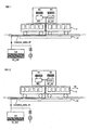
- the Figures 1 to 6 represent an example of the energy regulation system described above as well as a method of operation of the system for a vehicle V on a path T between a starting station S1 according to the Figures 1, 2 and an arrival station S2 according to the Figures 5, 6 .
- the stations S1, S2 comprise, for example, a platform (for the length of the stations S1, S2) for the passengers such as a conventional station stop for a metro, a tramway, a bus, etc.
- a battery BAT (with high specific energy unlike the super-capacitor) with a charge level N1 is also embedded in the vehicle.
- the vehicle here includes two wagons at least one of which is a tractor or propeller. Via a traction rail RT on the ground along the platform, an electric contact is made between the vehicle and a second supercapacitor SC_EXT (on the ground) as a SITRAS SES system previously mentioned with a level of charge or N3 energy storage.
- the starting station comprises an electric CHARGE_AREA charge area that can charge the SC_INT storage means of the vehicle and which is activated in charging mode when the residual energy, that is, that is, the level N2 of said vehicle storage means SC_INT is less than a variable threshold.
- the CHARGE_AREA charging area can identically charge the battery.
- the energy flows will be represented by thick arrows and explicitly indicate the various emitters and the energy receivers.
- the vehicle is stationary at departure station S1. Feeding by the SITRAS SES assisted RT rail with the SC_EXT supercapacitor on the ground completes the load of the SC_INT supercapacitor on the vehicle V and, if necessary, the BAT battery.
- the vehicle starts with an increasing speed V0 (acceleration) and the power supply via the SITRAS SES system's power-assisted rail provides the energy required for starting, because as long as the contact via the rail RT is possible, a maximum of energy of SC_EXT super capacitor on the ground must be used to save the SC_INT supercapacitor.
- the on-board supercapacitor SC_INT and the BAT battery are further supported.
- the levels N1, N2 of the battery and the on-board supercapacitor SC_INT remain respectively at an adequate or maximum charge level.
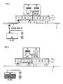
- Figure 3 represents the phase where the contact between the vehicle V (for example, via its wheel furthest downstream) to the rail RT is no longer ensured, because the vehicle engages on the path T out of the departure station S1.
- the vehicle On the path T between the departure station S1 and the arrival station S2, the vehicle is autonomous and therefore electrically isolated from a source of energy external to the vehicle.
- Figure 4 shows the vehicle on the path T, after its acceleration and a stabilized speed phase V2, which is about to slow down when approaching the arrival station S2.
- the level N2 of the on-board super-capacitor SC_INT can then be at its minimum. If a need, of energy turns out, BAT battery will take over as previously described. As soon as the braking is activated, the speed V2 decreases, but the kinetic energy recovered is channeled to the on-board supercapacitor SC_INT and / or the battery. The braking energy can then be advantageously stored (up to 40% of the kinetic energy is recovered). Furthermore, during these phases, the SITRAS SES system (s) with an SC_EXT supercapacitor on the ground is / are recharged (level N3 up) and ready for the arrival of an approaching vehicle.
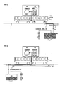
- the arrival at station S2 is represented at figure 5 for the vehicle V at a braking speed V3.
- the front of the vehicle is in contact first with the traction rail RT (for example, via a shoe between the vehicle and the rail on the ground) which will allow to already complete the load of the means on-board storage SC_INT, BAT, thanks to the supercapacitor SC_EXT on the ground loaded to a high level N3, this before the complete stop of the vehicle.
- Other uses of the energy stored in the supercapacitor SC_EXT on the ground can be envisaged, such as to supplement the on-board storage means SC_INT, BAT of the vehicle if another vehicle blocked in station or to allow other mechanical actions requiring high power.
- the braking energy and the power supply of the SITRAS SES system with the SITRAS SES integrated charging system and, if necessary, the BAT battery can also be used as additional energy for as long as the vehicle is in operation. load area.
- the vehicle stops at the station to allow passengers to go up or down.
- the load of the on-board supercapacitor SC_INT and if necessary the battery BAT is carried out by the supercapacitor SC_EXT, whose charge level N3 then re-decreases, however to satisfy the deterministic objectives of a next trip.
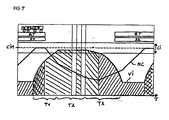
- the figure 7 represents an example of the level of charge NC of the on-board supercapacitor SC_INT according to the speed VI of the vehicle V on a path T between two stations S1, S2 (each with a traction rail RT) with reference to the Figures 1 to 6 .
- the hatching amounts to the right symbolize a charge of the on-board supercapacitor SC_INT (and / or the battery), the simple hatchings rising towards the left symbolize a discharge of the super-capacitor embedded SC_INT (and / or the battery) and the crossed hatches symbolize a maintenance (non-use) of the on-board supercapacitor SC_INT (and / or the battery).
- the train is stationary (constant speed VI because zero, while the load is running to a target load threshold CIM in an interval CI also said of target according to the given energy objectives), then during its phase of acceleration of duration T1, the charge level NC remains constant as long as a contact or a ground-vehicle energy flow is still possible.
- the vehicle has passed the traction rail (therefore the possible load area)
- only the own on-board supercapacitor SC_INT is used to continue the T1 acceleration phase which requires a high power.
- the energy relays between the two supercapacitors on the ground, and then embedded is assured.
- the speed VI remains constant.
- a power effort is not necessarily useful, if the terrain is for example flat.
- Uses of the battery instead of or in compensation mode of the on-board super-capacitor SC_INT can then be performed preferably in a short manner.
- the vehicle NC load level decreases irreparably, so that the speed VI at least is maintained at a desired and constant value.
- this target zone CI corresponds to a variation between 5 and 10% of the nominal load to ensure a number of cycles of more than 300,000 on current batteries.
- Supercapacitors have higher life cycles, between 500,000 and 1 million depending on current technology.
Landscapes
- Engineering & Computer Science (AREA)
- Power Engineering (AREA)
- Mechanical Engineering (AREA)
- Transportation (AREA)
- Life Sciences & Earth Sciences (AREA)
- Sustainable Development (AREA)
- Sustainable Energy (AREA)
- Electric Propulsion And Braking For Vehicles (AREA)
- Charge And Discharge Circuits For Batteries Or The Like (AREA)
Claims (18)
- Energieregulierungssystem für ein Fahrzeug (V) für den öffentlichen Verkehr zwischen einer Abgangsstation (S1) und einer Ankunftsstation (S2), die voneinander durch eine vorgegebene Strecke (T) getrennt sind, umfassend: ein in das Fahrzeug integriertes, elektrisches Hochleistungsspeichermittel (SC_INT), bei dem:- eine beim Bremsen des Fahrzeugs zurückgewonnene Energie im Speichermittel gespeichert wird,- eine Batterie (BAT) mit hoher Energiedichte im Fahrzeug angeordnet ist,dadurch gekennzeichnet, dass
mindestens die Abgangsstation einen elektrischen Ladebereich (CHARGE_AREA) umfasst, der das Speichermittel (SC_INT) des Fahrzeugs aufladen kann und dessen Ladebetrieb aktiviert wird, sobald die Restenergie des Speichermittels (SC_INT) des Fahrzeugs einen variablen Schwellenwert unterschreitet, welcher von der mindestens bis zur Ankunftsstation (S2) vorausgeschätzten Energiebilanz des Fahrzeugs abhängig ist,- das elektrische Hochleistungsspeichermittel (SC_INT) mindestens bei einer Beschleunigung eine Antriebsenergie an das Fahrzeug abgibt;- die elektrische Batterie (BAT) mit hoher Energiedichte bei einer konstanten Geschwindigkeit des Fahrzeugs ergänzend zum Speichermittel (SC_INT) des Fahrzeugs eine elektrische Energie an das Fahrzeug abgibt. - System nach Anspruch 1, bei dem:- der Ladebereich (CHARGE_AREA) mit einer elektrischen Energiequelle wie einem Stromnetz, einem Generator wie einem Motor oder einer Brennstoffzelle, einem Akkumulator wie einer Batterie oder einem Schwungrad oder einem anderen elektrischen Speichermittel (SC_EXT) wie einer kapazitiven Hochleistungsvorrichtung verbunden ist,- der Ladebereich über eine endliche Bewegungslänge des Fahrzeugs in der Station einen elektrischen Kontakt umfasst, der das Speichermittel (SC_INT) des Fahrzeugs mit dieser Quelle koppelt, idealerweise mittels mindestens einer Stromschiene (RT) oder einer Fahrleitung mit Schleifstück oder über ein induktives Energiezuführungssystem ohne Schleifstück.
- System nach Anspruch 2, bei dem die endliche Länge vor und/oder hinter einem Haltepunkt des Fahrzeugs in der Station veränderlich ist, idealerweise durch Ausdehnen des elektrischen Ladebereichs.
- System nach einem der vorangehenden Ansprüche, bei dem das Fahrzeug auf der Strecke zwischen der Abgangsstation und der Ankunftsstation von einer fahrzeugexternen Energiequelle elektrisch isoliert ist.
- System nach einem der vorangehenden Ansprüche mit einer Einheit zur Steuerung des Energieaustauschs zwischen der Batterie (BAT), dem Speichermittel (SC_INT) und einem Antriebselement des Fahrzeugs, so dass beispielsweise beim Bremsen eine zurückgewonnene Energie so gelenkt werden kann, dass sie unabhängig die Batterie (BAT) und/oder das Speichermittel (SC_INT) des Fahrzeugs auflädt.
- System nach einem der vorangehenden Ansprüche, bei dem gelegentlich die Batterie das Speichermittel (SC_INT) des Fahrzeugs auflädt oder eine andere Energieverbrauchsquelle des Fahrzeugs speist.
- System nach Anspruch 6, bei dem ein Entladen der Batterie unter einen Schwellenwert für einen besseren Wirkungsgrad der Batterie auf wenige Male und einen geringen Umfang unter diesem Schwellenwert begrenzt wird, um die Lebensdauer der Batterie zu schützen.
- System nach einem der Ansprüche 6 oder 7, bei dem gelegentlich und zulasten der Lebensdauer der Batterie ein Entladen der Batterie über den geringen Umfang hinaus in mindestens einem der folgenden Fälle erzwungen wird:- im Notbetrieb oder Wiederaufladebetrieb des Speichermittels (SC_INT) des Fahrzeugs, insbesondere bei einer Abfahrt des Fahrzeugs;- im Notbetrieb eines Ladebereichs (CHARGE_AREA), der außer Betrieb ist;- beim Schieben oder Ziehen eines anderen Fahrzeugs.
- System nach einem der Ansprüche 6 bis 8, bei dem ein Aufladen der Batterie durch Rückgewinnung von Bremsenergie und/oder in der Station erfolgt.
- System nach einem der Ansprüche 6 bis 9, bei dem eine Steuereinheit zur Kalibrierung und zum Erhalt der Energiestärken und -übertragungen in das Fahrzeug integriert ist.
- System nach einem der vorangehenden Ansprüche mit einem Rechner zur energetischen Vorausschätzung auf der Grundlage mehrerer Parameter zwischen den Stationen, der in das Fahrzeug integriert sein kann und mit einer Steuereinheit im Ladebereich in Verbindung gebracht werden kann und/oder umgekehrt.
- System nach Anspruch 11, bei dem die Parameter kinetische Parameter - Länge und Profil der Strecke, geforderte oder mögliche Geschwindigkeit, Gewicht des Fahrzeugs und der Fahrgäste usw. - und Umweltparameter - Stärke der Klimatisierung in Abhängigkeit von einer Außentemperatur, Innen- und Außenbeleuchtung des Fahrzeugs, Kommunikations-oder Sicherheitssysteme für die Fahrgäste usw. - sind.
- System nach einem der vorangehenden Ansprüche 11 oder 12, bei dem der Rechner mit einer Steuereinheit mit Prioritätsstufen verbunden ist, um einen hohen Energieverbrauch bei vorrangigen Parametern durch Energieeinsparungen bei nachrangigen Parametern auszugleichen.
- System nach einem der vorangehenden Ansprüche 11 bis 13, bei dem im Fall der Störung eines Ladebereichs in einer der Stationen der Rechner die Geschwindigkeit des Fahrzeugs auf einer späteren Strecke herabsetzt.
- System nach einem der vorangehenden Ansprüche, bei dem mindestens ein zusätzlicher Ladebereich auf der Strecke zwischen der Abgangsstation und der Ankunftsstation angeordnet ist, der insbesondere ein Wiederaufladen des Speichermittels (SC-INT) des Fahrzeugs ohne Halt des Fahrzeugs ermöglicht.
- System nach einem der vorangehenden Ansprüche, bei dem ein Speichermittel eines ersten Fahrzeugs seine elektrische Energie und/oder die eines oder mehrerer anderer Fahrzeuge, die vom ersten Fahrzeug gezogen oder geschoben werden, abgibt und/oder speichert.
- System nach einem der vorangehenden Ansprüche, bei dem ein Speichermittel eines ersten Fahrzeugs die elektrische Energie eines oder mehrerer anderer Fahrzeuge, die vom ersten Fahrzeug gezogen oder geschoben werden, abgibt und/oder speichert.
- System nach einem der vorangehenden Ansprüche, bei dem das Speichermittel (SC-INT) ein Super-Kondensator ist.
Priority Applications (1)
| Application Number | Priority Date | Filing Date | Title |
|---|---|---|---|
| EP07724178A EP2018291B1 (de) | 2006-05-19 | 2007-04-12 | Energieregulierungssystem für ein fahrzeug |
Applications Claiming Priority (3)
| Application Number | Priority Date | Filing Date | Title |
|---|---|---|---|
| EP06290825A EP1864849A1 (de) | 2006-05-19 | 2006-05-19 | Energieregelsystem für ein Fahrzeug |
| EP07724178A EP2018291B1 (de) | 2006-05-19 | 2007-04-12 | Energieregulierungssystem für ein fahrzeug |
| PCT/EP2007/003237 WO2007134674A1 (fr) | 2006-05-19 | 2007-04-12 | Systeme de regulation d'energie pour un vehicule |
Publications (2)
| Publication Number | Publication Date |
|---|---|
| EP2018291A1 EP2018291A1 (de) | 2009-01-28 |
| EP2018291B1 true EP2018291B1 (de) | 2011-08-17 |
Family
ID=37075828
Family Applications (2)
| Application Number | Title | Priority Date | Filing Date |
|---|---|---|---|
| EP06290825A Withdrawn EP1864849A1 (de) | 2006-05-19 | 2006-05-19 | Energieregelsystem für ein Fahrzeug |
| EP07724178A Active EP2018291B1 (de) | 2006-05-19 | 2007-04-12 | Energieregulierungssystem für ein fahrzeug |
Family Applications Before (1)
| Application Number | Title | Priority Date | Filing Date |
|---|---|---|---|
| EP06290825A Withdrawn EP1864849A1 (de) | 2006-05-19 | 2006-05-19 | Energieregelsystem für ein Fahrzeug |
Country Status (6)
| Country | Link |
|---|---|
| US (1) | US8027760B2 (de) |
| EP (2) | EP1864849A1 (de) |
| KR (1) | KR101066765B1 (de) |
| CN (1) | CN101563253B (de) |
| ES (1) | ES2369062T3 (de) |
| WO (1) | WO2007134674A1 (de) |
Cited By (1)
| Publication number | Priority date | Publication date | Assignee | Title |
|---|---|---|---|---|
| EP2689953B1 (de) | 2011-03-22 | 2018-03-14 | Construcciones Y Auxiliar de Ferrocarriles, S.A. | Elektrisches ladesystem für energiespeicher von schienenfahrzeugen |
Families Citing this family (55)
| Publication number | Priority date | Publication date | Assignee | Title |
|---|---|---|---|---|
| DE102007032776A1 (de) * | 2007-07-13 | 2009-01-15 | Siemens Ag | Elektrisches Antriebssystem |
| US8358107B2 (en) | 2007-12-31 | 2013-01-22 | Intel Corporation | Bidirectional power management techniques |
| DE102008030342A1 (de) * | 2008-06-26 | 2009-12-31 | Siemens Aktiengesellschaft | Vorrichtung zum Versorgen eines elektrisch angetriebenen spurgeführte Fahrzeugs mit elektrischer Energie |
| FR2933245B1 (fr) * | 2008-06-27 | 2010-09-03 | Peugeot Citroen Automobiles Sa | Dispositif de recharge d'un systeme de stockage comportant deux elements de stockage et procedes d'utilisation d'un tel dispositif de recharge associes |
| WO2010003711A1 (de) * | 2008-07-08 | 2010-01-14 | Siemens Aktiengesellschaft | Adaptereinrichtung und verfahren zum energetischen laden eines fahrzeugs |
| DE102009017556A1 (de) | 2009-04-17 | 2010-10-21 | Bär, Ralf, Dipl.-Ing. | Verfahren zum Betreiben einer Montageanlage und fahrerlose, mobile Montage- und/oder Materialtransporteinheit hierfür |
| US8749199B2 (en) * | 2009-05-08 | 2014-06-10 | William Gibbens Redmann | Method and apparatus for charging an electric vehicle from a streetlight |
| JP5622380B2 (ja) * | 2009-11-09 | 2014-11-12 | 株式会社東芝 | 給電システム |
| CN102712260B (zh) * | 2009-12-28 | 2016-01-20 | 山特维克矿山工程机械有限公司 | 采矿车辆及其能量供给的方法 |
| FI123470B (fi) * | 2009-12-28 | 2013-05-31 | Sandvik Mining & Constr Oy | Kaivosajoneuvo ja menetelmä sen energian syöttöön |
| DE102010021705B4 (de) * | 2010-05-27 | 2017-10-19 | Sew-Eurodrive Gmbh & Co Kg | Verfahren zum Transportieren eines Objektes, Fahrzeug, Anlage |
| US20110302078A1 (en) | 2010-06-02 | 2011-12-08 | Bryan Marc Failing | Managing an energy transfer between a vehicle and an energy transfer system |
| US8684150B2 (en) | 2010-06-15 | 2014-04-01 | General Electric Company | Control assembly and control method for supplying power to electrified rail vehicles |
| JP5146855B2 (ja) * | 2010-08-09 | 2013-02-20 | 村田機械株式会社 | 天井走行車システム |
| DE112011103613T5 (de) | 2010-10-29 | 2013-08-14 | Abb Research Ltd. | Entsenden von mobilen Energie-Ressourcen zum Antworten auf elektrische Stromnetzzustände |
| US20120191517A1 (en) * | 2010-12-15 | 2012-07-26 | Daffin Jr Mack Paul | Prepaid virtual card |
| KR101273267B1 (ko) * | 2011-03-15 | 2013-06-11 | 한국철도기술연구원 | 에너지저장장치를 이용한 지능형 에너지 관리 시스템 |
| FR2975351B1 (fr) * | 2011-05-19 | 2016-05-06 | Alstom Transport Sa | Procede d'alimentation electrique d'un vehicule ferroviaire, systeme d'alimentation en station, systeme de stockage d'energie embarque et vehicule ferroviaire associes |
| DE102011076787A1 (de) | 2011-05-31 | 2012-12-06 | Siemens Ag | Energieversorgung |
| US9545854B2 (en) * | 2011-06-13 | 2017-01-17 | General Electric Company | System and method for controlling and powering a vehicle |
| DE102011078869A1 (de) * | 2011-07-08 | 2013-01-10 | Robert Bosch Gmbh | Verfahren und Vorrichtung zum Betreiben eines Fahrzeugs, Computerprogramm, Computerprogramm-Produkt |
| DE102011110641A1 (de) * | 2011-08-18 | 2013-02-21 | Deutsches Zentrum für Luft- und Raumfahrt e.V. | Energieversorgungsvorrichtung |
| EP2755100A4 (de) * | 2011-09-06 | 2016-06-08 | Murata Machinery Ltd | Lieferfahrzeugsystem und ladeverfahren für lieferfahrzeuge |
| JP5494633B2 (ja) * | 2011-12-02 | 2014-05-21 | コニカミノルタ株式会社 | 電子機器および画像形成装置 |
| JP5901318B2 (ja) | 2012-02-02 | 2016-04-06 | 三菱重工業株式会社 | 充放電制御装置、充電制御方法、放電制御方法、及びプログラム |
| US8789473B2 (en) | 2012-02-24 | 2014-07-29 | Electro-Motive Diesel Inc. | Flow battery control system for a locomotive |
| EP2849312A4 (de) * | 2012-04-12 | 2016-06-01 | Hitachi Ltd | Fahrzeugsteuerungssystem |
| DE102012217184A1 (de) * | 2012-09-24 | 2014-06-12 | Bayerische Motoren Werke Aktiengesellschaft | Energiemanagement für Kraftfahrzeug mit Koppelspeichervorrichtung |
| US20140239879A1 (en) * | 2013-02-22 | 2014-08-28 | Electro-Motive Diesel, Inc. | Battery charging system |
| US11565598B2 (en) | 2013-03-15 | 2023-01-31 | Symbotic Llc | Rover charging system with one or more charging stations configured to control an output of the charging station independent of a charging station status |
| JP6134863B2 (ja) | 2013-05-08 | 2017-05-24 | ボルボトラックコーポレーション | 非鉄道車両のためのエネルギー制御システム |
| FR3008041B1 (fr) * | 2013-07-05 | 2016-12-09 | Blue Solutions | Vehicule electrique et installation de transport associee |
| CN104682469B (zh) * | 2013-12-02 | 2017-04-12 | 财团法人车辆研究测试中心 | 能量管理装置及方法 |
| US9114713B2 (en) * | 2013-12-24 | 2015-08-25 | Automotive Research & Testing Center | Energy management device and method for a vehicle |
| US10144294B2 (en) | 2014-11-28 | 2018-12-04 | Hitachi Rail Italy S.P.A. | Auxiliary energy management system and method for operating an auxiliary system |
| FR3029485B1 (fr) * | 2014-12-03 | 2018-03-16 | Alstom Transport Technologies | Dispositif aeraulique de refroidissement d'un element d'un vehicule ferroviaire et vehicule ferroviaire correspondant |
| FR3032921B1 (fr) * | 2015-02-23 | 2019-01-25 | Metrolab | Systeme de transport ferroviaire autonome en energie electrique |
| EP3150419B1 (de) * | 2015-09-30 | 2021-06-23 | Mitsubishi Electric R&D Centre Europe B.V. | Verfahren und system zur reduzierung des energieverbrauchs von eisenbahnsystemen |
| DE102016202813B4 (de) * | 2016-02-24 | 2022-01-27 | Bayerische Motoren Werke Aktiengesellschaft | Verfahren zur Steuerung des elektrischen Ladens einer Gruppe von Fahrzeugen |
| DE102016208082A1 (de) * | 2016-05-11 | 2017-11-16 | Volkswagen Ag | Brennstoffzellenfahrzeug mit einer Mehrzahl wählbarer Betriebsmodi |
| DE102016212071B4 (de) * | 2016-07-04 | 2019-02-14 | Audi Ag | Verfahren zum Betreiben eines elektrisch angetriebenen oder auch elektrisch antreibbaren Fahrzeugs sowie Fahrzeug |
| GB2552483B (en) * | 2016-07-25 | 2020-04-22 | Jaguar Land Rover Ltd | Battery management apparatus and method |
| CN107576389A (zh) * | 2017-09-14 | 2018-01-12 | 浙江海洋大学 | 一种船舶轴系扭振监测装置 |
| CN108832611B (zh) * | 2018-06-11 | 2023-09-19 | 西南交通大学 | 一种轨道交通应急电源系统与控制方法 |
| CN109204012A (zh) * | 2018-09-03 | 2019-01-15 | 中车大连机车车辆有限公司 | 用于轨道车辆的动力制动控制系统及轨道车辆 |
| KR102112039B1 (ko) | 2018-12-26 | 2020-06-15 | 한국철도기술연구원 | 교직겸용 전기철도차량 시스템의 무가선 운행성능 시험방법 및 그 시험장치 |
| CN109657400B (zh) * | 2019-01-02 | 2023-01-20 | 中车株洲电力机车有限公司 | 一种有轨电车混合供电放电牵引仿真计算方法 |
| DE102019210645A1 (de) * | 2019-07-18 | 2021-01-21 | Siemens Mobility GmbH | Fahrzeug und Verfahren zum Betreiben eines Fahrzeugs |
| WO2021012525A1 (zh) * | 2019-07-24 | 2021-01-28 | 苏州宝时得电动工具有限公司 | 自动行走设备回归停靠站的控制方法及自动行走设备 |
| JP7600263B2 (ja) * | 2020-04-24 | 2024-12-16 | オカド・イノベーション・リミテッド | 積荷取扱装置用のエネルギー貯蔵システム |
| CN114567027A (zh) * | 2020-11-27 | 2022-05-31 | 厦门雅迅网络股份有限公司 | 一种基于地形预测的动力电池组均衡方法 |
| DE102021211559A1 (de) | 2021-10-13 | 2023-04-13 | Karlsruher Institut für Technologie, Körperschaft des öffentlichen Rechts | Ansteuerung eines Transportfahrzeugs |
| US12024213B2 (en) * | 2021-12-02 | 2024-07-02 | Ranjan Kumar Gupta | System and method of electrical connection of rail vehicle for storing, transporting and delivering electric energy |
| GB202203386D0 (en) * | 2022-03-11 | 2022-04-27 | Tdi Greenway Tech Ltd | Rapid charging arrangement |
| KR102796332B1 (ko) * | 2024-06-25 | 2025-04-16 | 비나텍주식회사 | 전력 공급 및 전력 소모에 따라 선택적으로 슈퍼커패시터 및 배터리를 연결하는 하이브리드 전원 장치 |
Family Cites Families (12)
| Publication number | Priority date | Publication date | Assignee | Title |
|---|---|---|---|---|
| US3955657A (en) * | 1974-02-15 | 1976-05-11 | Oscar Bossi | Electric traction transportation system with storage battery powered vehicles and fast recharge at the vehicle stops |
| DE2405198A1 (de) * | 1973-02-15 | 1974-08-22 | Oscar Dr Ing Bossi | Batteriebetriebenes transportsystem, insbesondere fuer den oeffentlichen nahverkehr |
| FR2336272A1 (fr) * | 1975-12-23 | 1977-07-22 | Cotravel | Dispositif de transport de surface par vehicules a moteur electrique de traction alimente par une batterie d'accumulateurs |
| US5669470A (en) * | 1994-05-05 | 1997-09-23 | H. R. Ross Industries, Inc. | Roadway-powered electric vehicle system |
| JP3211699B2 (ja) * | 1996-09-17 | 2001-09-25 | トヨタ自動車株式会社 | 動力出力装置 |
| US6380637B1 (en) * | 1996-09-19 | 2002-04-30 | Ztek Corporation | Off-board station and an electricity exchanging system suitable for use with a mobile vehicle power system |
| FR2780684B1 (fr) * | 1998-07-02 | 2002-02-01 | Anf Ind | Reseau de transport en commun avec vehicules electriques |
| FR2782680B1 (fr) * | 1998-08-28 | 2000-11-17 | Alstom Technology | Systeme d'alimentation d'un vehicule a traction electrique |
| FR2819759B1 (fr) * | 2001-01-24 | 2003-05-23 | Alstom | Systeme d'alimentation d'un vehicule a traction electrique |
| US7430967B2 (en) * | 2001-03-27 | 2008-10-07 | General Electric Company | Multimode hybrid energy railway vehicle system and method |
| FR2871744B1 (fr) * | 2004-06-21 | 2008-02-22 | Alstom Sa | Dispositif d'alimentation embarque sur un vehicule de traction, procede d'alimentation et support d'enregistrement de ce procede |
| US7595597B2 (en) * | 2006-01-18 | 2009-09-29 | General Electric Comapany | Vehicle propulsion system |
-
2006
- 2006-05-19 EP EP06290825A patent/EP1864849A1/de not_active Withdrawn
-
2007
- 2007-04-12 KR KR1020087030841A patent/KR101066765B1/ko not_active Expired - Fee Related
- 2007-04-12 EP EP07724178A patent/EP2018291B1/de active Active
- 2007-04-12 ES ES07724178T patent/ES2369062T3/es active Active
- 2007-04-12 WO PCT/EP2007/003237 patent/WO2007134674A1/fr not_active Ceased
- 2007-04-12 CN CN2007800181880A patent/CN101563253B/zh not_active Expired - Fee Related
-
2008
- 2008-11-19 US US12/273,992 patent/US8027760B2/en active Active
Cited By (1)
| Publication number | Priority date | Publication date | Assignee | Title |
|---|---|---|---|---|
| EP2689953B1 (de) | 2011-03-22 | 2018-03-14 | Construcciones Y Auxiliar de Ferrocarriles, S.A. | Elektrisches ladesystem für energiespeicher von schienenfahrzeugen |
Also Published As
| Publication number | Publication date |
|---|---|
| WO2007134674A1 (fr) | 2007-11-29 |
| CN101563253B (zh) | 2011-10-19 |
| EP2018291A1 (de) | 2009-01-28 |
| US20090138149A1 (en) | 2009-05-28 |
| KR101066765B1 (ko) | 2011-09-21 |
| ES2369062T3 (es) | 2011-11-24 |
| CN101563253A (zh) | 2009-10-21 |
| KR20090018140A (ko) | 2009-02-19 |
| US8027760B2 (en) | 2011-09-27 |
| EP1864849A1 (de) | 2007-12-12 |
Similar Documents
| Publication | Publication Date | Title |
|---|---|---|
| EP2018291B1 (de) | Energieregulierungssystem für ein fahrzeug | |
| EP1241041B1 (de) | Fahrzeug mit Super-Kondensator zur Bremsenergie-Rückgewinnung | |
| US10144294B2 (en) | Auxiliary energy management system and method for operating an auxiliary system | |
| CN105324269B (zh) | 利用车载太阳能电池的充电控制装置 | |
| RU2570855C2 (ru) | Способ и система транспортного средства | |
| EP2648953B1 (de) | Verfahren zur steuerung eines hybridautos und an ein derartiges verfahren adaptiertes hybridauto | |
| EP2885147B1 (de) | Verfahren zur begrenzung des drehmoments einer elektrischen maschine eines hybridfahrzeugs mit einer drehzahlregelungssystem | |
| EP2162313B1 (de) | Einspeisungseinrichtung eines eisenbahnfahrzeugs | |
| WO2015110669A2 (fr) | Système de transport ferroviaire autonome en énergie électrique | |
| US20230336005A1 (en) | Solar charging of multiple battery banks | |
| WO2014118476A1 (fr) | Dispositif d'alimentation electrique d'un reseau de bord de vehicule automobile hybride | |
| WO2019073136A1 (fr) | Systeme de commande avec restriction du ratio de distribution du couple | |
| FR3001684A1 (fr) | Procede de gestion de la recuperation d'energie pour un vehicule hybride comportant un systeme de regulation ou de limitation de vitesse | |
| WO2016059356A2 (fr) | Véhicule hybride et procédé d'hybridation d'un véhicule | |
| EP2105366A2 (de) | Verfahren und Vorrichtung zur Kontrolle einer elektrischen Ladung | |
| EP3452324B1 (de) | Verfahren zur steuerung einer elektrischen maschine eines hybridantriebsstrangs auf basis des vom fahrer ausgewählten sollwerts | |
| FR3078204A1 (fr) | Gestion de l’energie electrique dans un vehicule automobile hybride | |
| US20240425030A1 (en) | Intelligent optimized energy storage control for electrified vehicles | |
| WO2012084282A2 (fr) | Méthode de réglage de puissance absorbée par au moins un véhicule alimenté électriquement | |
| FR2884887A1 (fr) | Systeme de transmission d'energie cinetique | |
| JP2016175501A (ja) | ハイブリッド車両及びその制御方法 | |
| FR3001666A1 (fr) | Tramway electrique et reseau de transport associe | |
| WO2020016491A1 (fr) | Procede de pilotage d'un groupe moto-propulseur comprenant un alterno-demarreur |
Legal Events
| Date | Code | Title | Description |
|---|---|---|---|
| PUAI | Public reference made under article 153(3) epc to a published international application that has entered the european phase |
Free format text: ORIGINAL CODE: 0009012 |
|
| 17P | Request for examination filed |
Effective date: 20081014 |
|
| AK | Designated contracting states |
Kind code of ref document: A1 Designated state(s): AT BE BG CH CY CZ DE DK EE ES FI FR GB GR HU IE IS IT LI LT LU LV MC MT NL PL PT RO SE SI SK TR |
|
| AX | Request for extension of the european patent |
Extension state: AL BA HR MK RS |
|
| DAX | Request for extension of the european patent (deleted) | ||
| RBV | Designated contracting states (corrected) |
Designated state(s): DE ES FR GB IT |
|
| RAP1 | Party data changed (applicant data changed or rights of an application transferred) |
Owner name: SIEMENS SAS |
|
| GRAP | Despatch of communication of intention to grant a patent |
Free format text: ORIGINAL CODE: EPIDOSNIGR1 |
|
| GRAS | Grant fee paid |
Free format text: ORIGINAL CODE: EPIDOSNIGR3 |
|
| GRAA | (expected) grant |
Free format text: ORIGINAL CODE: 0009210 |
|
| AK | Designated contracting states |
Kind code of ref document: B1 Designated state(s): DE ES FR GB IT |
|
| REG | Reference to a national code |
Ref country code: GB Ref legal event code: FG4D Free format text: NOT ENGLISH |
|
| REG | Reference to a national code |
Ref country code: DE Ref legal event code: R096 Ref document number: 602007016569 Country of ref document: DE Effective date: 20111027 |
|
| REG | Reference to a national code |
Ref country code: ES Ref legal event code: FG2A Ref document number: 2369062 Country of ref document: ES Kind code of ref document: T3 Effective date: 20111124 |
|
| PLBE | No opposition filed within time limit |
Free format text: ORIGINAL CODE: 0009261 |
|
| STAA | Information on the status of an ep patent application or granted ep patent |
Free format text: STATUS: NO OPPOSITION FILED WITHIN TIME LIMIT |
|
| 26N | No opposition filed |
Effective date: 20120521 |
|
| REG | Reference to a national code |
Ref country code: DE Ref legal event code: R097 Ref document number: 602007016569 Country of ref document: DE Effective date: 20120521 |
|
| PGFP | Annual fee paid to national office [announced via postgrant information from national office to epo] |
Ref country code: GB Payment date: 20150414 Year of fee payment: 9 |
|
| REG | Reference to a national code |
Ref country code: FR Ref legal event code: PLFP Year of fee payment: 10 |
|
| GBPC | Gb: european patent ceased through non-payment of renewal fee |
Effective date: 20160412 |
|
| PG25 | Lapsed in a contracting state [announced via postgrant information from national office to epo] |
Ref country code: GB Free format text: LAPSE BECAUSE OF NON-PAYMENT OF DUE FEES Effective date: 20160412 |
|
| REG | Reference to a national code |
Ref country code: FR Ref legal event code: PLFP Year of fee payment: 11 |
|
| REG | Reference to a national code |
Ref country code: FR Ref legal event code: PLFP Year of fee payment: 12 |
|
| REG | Reference to a national code |
Ref country code: DE Ref legal event code: R082 Ref document number: 602007016569 Country of ref document: DE Representative=s name: DEFFNER, ROLF, DR., DE Ref country code: DE Ref legal event code: R081 Ref document number: 602007016569 Country of ref document: DE Owner name: SIEMENS MOBILITY S.A.S., FR Free format text: FORMER OWNER: SIEMENS SAS, SAINT-DENIS, FR |
|
| REG | Reference to a national code |
Ref country code: ES Ref legal event code: PC2A Owner name: SIEMENS MOBILITY S.A.S. Effective date: 20210423 |
|
| PGFP | Annual fee paid to national office [announced via postgrant information from national office to epo] |
Ref country code: DE Payment date: 20240619 Year of fee payment: 18 |
|
| PGFP | Annual fee paid to national office [announced via postgrant information from national office to epo] |
Ref country code: IT Payment date: 20240422 Year of fee payment: 18 Ref country code: FR Payment date: 20240415 Year of fee payment: 18 |
|
| PGFP | Annual fee paid to national office [announced via postgrant information from national office to epo] |
Ref country code: ES Payment date: 20240724 Year of fee payment: 18 |
|
| REG | Reference to a national code |
Ref country code: DE Ref legal event code: R119 Ref document number: 602007016569 Country of ref document: DE |
|
| PG25 | Lapsed in a contracting state [announced via postgrant information from national office to epo] |
Ref country code: DE Free format text: LAPSE BECAUSE OF NON-PAYMENT OF DUE FEES Effective date: 20251104 |
|
| PG25 | Lapsed in a contracting state [announced via postgrant information from national office to epo] |
Ref country code: FR Free format text: LAPSE BECAUSE OF NON-PAYMENT OF DUE FEES Effective date: 20250430 |