EP2105366A2 - Verfahren und Vorrichtung zur Kontrolle einer elektrischen Ladung - Google Patents
Verfahren und Vorrichtung zur Kontrolle einer elektrischen Ladung Download PDFInfo
- Publication number
- EP2105366A2 EP2105366A2 EP09155954A EP09155954A EP2105366A2 EP 2105366 A2 EP2105366 A2 EP 2105366A2 EP 09155954 A EP09155954 A EP 09155954A EP 09155954 A EP09155954 A EP 09155954A EP 2105366 A2 EP2105366 A2 EP 2105366A2
- Authority
- EP
- European Patent Office
- Prior art keywords
- electric
- electrical
- storage unit
- charge
- load
- Prior art date
- Legal status (The legal status is an assumption and is not a legal conclusion. Google has not performed a legal analysis and makes no representation as to the accuracy of the status listed.)
- Withdrawn
Links
- 238000000034 method Methods 0.000 title claims abstract description 12
- 230000002441 reversible effect Effects 0.000 description 9
- 101100536354 Drosophila melanogaster tant gene Proteins 0.000 description 6
- 230000006870 function Effects 0.000 description 5
- 238000011084 recovery Methods 0.000 description 5
- 238000010586 diagram Methods 0.000 description 4
- 230000007704 transition Effects 0.000 description 4
- 238000010521 absorption reaction Methods 0.000 description 3
- 239000006096 absorbing agent Substances 0.000 description 2
- 238000004378 air conditioning Methods 0.000 description 2
- 230000007423 decrease Effects 0.000 description 2
- 230000000694 effects Effects 0.000 description 2
- 238000005457 optimization Methods 0.000 description 2
- 238000005381 potential energy Methods 0.000 description 2
- 230000000750 progressive effect Effects 0.000 description 2
- 230000000630 rising effect Effects 0.000 description 2
- 206010063493 Premature ageing Diseases 0.000 description 1
- 208000032038 Premature aging Diseases 0.000 description 1
- 230000001133 acceleration Effects 0.000 description 1
- 230000008901 benefit Effects 0.000 description 1
- 230000005540 biological transmission Effects 0.000 description 1
- 238000004364 calculation method Methods 0.000 description 1
- 239000003990 capacitor Substances 0.000 description 1
- 230000006378 damage Effects 0.000 description 1
- 238000001514 detection method Methods 0.000 description 1
- 230000006866 deterioration Effects 0.000 description 1
- 238000005516 engineering process Methods 0.000 description 1
- 239000000446 fuel Substances 0.000 description 1
- 230000012447 hatching Effects 0.000 description 1
- 238000010438 heat treatment Methods 0.000 description 1
- 238000009396 hybridization Methods 0.000 description 1
- 230000006872 improvement Effects 0.000 description 1
- 238000012423 maintenance Methods 0.000 description 1
- 230000021715 photosynthesis, light harvesting Effects 0.000 description 1
- 230000008569 process Effects 0.000 description 1
- 230000009467 reduction Effects 0.000 description 1
- 230000001172 regenerating effect Effects 0.000 description 1
- 238000009877 rendering Methods 0.000 description 1
- 238000010200 validation analysis Methods 0.000 description 1
Images


Classifications
-
- B—PERFORMING OPERATIONS; TRANSPORTING
- B60—VEHICLES IN GENERAL
- B60L—PROPULSION OF ELECTRICALLY-PROPELLED VEHICLES; SUPPLYING ELECTRIC POWER FOR AUXILIARY EQUIPMENT OF ELECTRICALLY-PROPELLED VEHICLES; ELECTRODYNAMIC BRAKE SYSTEMS FOR VEHICLES IN GENERAL; MAGNETIC SUSPENSION OR LEVITATION FOR VEHICLES; MONITORING OPERATING VARIABLES OF ELECTRICALLY-PROPELLED VEHICLES; ELECTRIC SAFETY DEVICES FOR ELECTRICALLY-PROPELLED VEHICLES
- B60L58/00—Methods or circuit arrangements for monitoring or controlling batteries or fuel cells, specially adapted for electric vehicles
- B60L58/10—Methods or circuit arrangements for monitoring or controlling batteries or fuel cells, specially adapted for electric vehicles for monitoring or controlling batteries
- B60L58/12—Methods or circuit arrangements for monitoring or controlling batteries or fuel cells, specially adapted for electric vehicles for monitoring or controlling batteries responding to state of charge [SoC]
-
- B—PERFORMING OPERATIONS; TRANSPORTING
- B60—VEHICLES IN GENERAL
- B60L—PROPULSION OF ELECTRICALLY-PROPELLED VEHICLES; SUPPLYING ELECTRIC POWER FOR AUXILIARY EQUIPMENT OF ELECTRICALLY-PROPELLED VEHICLES; ELECTRODYNAMIC BRAKE SYSTEMS FOR VEHICLES IN GENERAL; MAGNETIC SUSPENSION OR LEVITATION FOR VEHICLES; MONITORING OPERATING VARIABLES OF ELECTRICALLY-PROPELLED VEHICLES; ELECTRIC SAFETY DEVICES FOR ELECTRICALLY-PROPELLED VEHICLES
- B60L7/00—Electrodynamic brake systems for vehicles in general
- B60L7/10—Dynamic electric regenerative braking
-
- B—PERFORMING OPERATIONS; TRANSPORTING
- B60—VEHICLES IN GENERAL
- B60W—CONJOINT CONTROL OF VEHICLE SUB-UNITS OF DIFFERENT TYPE OR DIFFERENT FUNCTION; CONTROL SYSTEMS SPECIALLY ADAPTED FOR HYBRID VEHICLES; ROAD VEHICLE DRIVE CONTROL SYSTEMS FOR PURPOSES NOT RELATED TO THE CONTROL OF A PARTICULAR SUB-UNIT
- B60W10/00—Conjoint control of vehicle sub-units of different type or different function
- B60W10/04—Conjoint control of vehicle sub-units of different type or different function including control of propulsion units
- B60W10/08—Conjoint control of vehicle sub-units of different type or different function including control of propulsion units including control of electric propulsion units, e.g. motors or generators
-
- B—PERFORMING OPERATIONS; TRANSPORTING
- B60—VEHICLES IN GENERAL
- B60W—CONJOINT CONTROL OF VEHICLE SUB-UNITS OF DIFFERENT TYPE OR DIFFERENT FUNCTION; CONTROL SYSTEMS SPECIALLY ADAPTED FOR HYBRID VEHICLES; ROAD VEHICLE DRIVE CONTROL SYSTEMS FOR PURPOSES NOT RELATED TO THE CONTROL OF A PARTICULAR SUB-UNIT
- B60W10/00—Conjoint control of vehicle sub-units of different type or different function
- B60W10/24—Conjoint control of vehicle sub-units of different type or different function including control of energy storage means
- B60W10/26—Conjoint control of vehicle sub-units of different type or different function including control of energy storage means for electrical energy, e.g. batteries or capacitors
-
- B—PERFORMING OPERATIONS; TRANSPORTING
- B60—VEHICLES IN GENERAL
- B60W—CONJOINT CONTROL OF VEHICLE SUB-UNITS OF DIFFERENT TYPE OR DIFFERENT FUNCTION; CONTROL SYSTEMS SPECIALLY ADAPTED FOR HYBRID VEHICLES; ROAD VEHICLE DRIVE CONTROL SYSTEMS FOR PURPOSES NOT RELATED TO THE CONTROL OF A PARTICULAR SUB-UNIT
- B60W20/00—Control systems specially adapted for hybrid vehicles
- B60W20/10—Controlling the power contribution of each of the prime movers to meet required power demand
- B60W20/13—Controlling the power contribution of each of the prime movers to meet required power demand in order to stay within battery power input or output limits; in order to prevent overcharging or battery depletion
-
- H—ELECTRICITY
- H02—GENERATION; CONVERSION OR DISTRIBUTION OF ELECTRIC POWER
- H02J—CIRCUIT ARRANGEMENTS OR SYSTEMS FOR SUPPLYING OR DISTRIBUTING ELECTRIC POWER; SYSTEMS FOR STORING ELECTRIC ENERGY
- H02J7/00—Circuit arrangements for charging or depolarising batteries or for supplying loads from batteries
- H02J7/14—Circuit arrangements for charging or depolarising batteries or for supplying loads from batteries for charging batteries from dynamo-electric generators driven at varying speed, e.g. on vehicle
- H02J7/1415—Circuit arrangements for charging or depolarising batteries or for supplying loads from batteries for charging batteries from dynamo-electric generators driven at varying speed, e.g. on vehicle with a generator driven by a prime mover other than the motor of a vehicle
-
- B—PERFORMING OPERATIONS; TRANSPORTING
- B60—VEHICLES IN GENERAL
- B60L—PROPULSION OF ELECTRICALLY-PROPELLED VEHICLES; SUPPLYING ELECTRIC POWER FOR AUXILIARY EQUIPMENT OF ELECTRICALLY-PROPELLED VEHICLES; ELECTRODYNAMIC BRAKE SYSTEMS FOR VEHICLES IN GENERAL; MAGNETIC SUSPENSION OR LEVITATION FOR VEHICLES; MONITORING OPERATING VARIABLES OF ELECTRICALLY-PROPELLED VEHICLES; ELECTRIC SAFETY DEVICES FOR ELECTRICALLY-PROPELLED VEHICLES
- B60L2240/00—Control parameters of input or output; Target parameters
- B60L2240/40—Drive Train control parameters
- B60L2240/42—Drive Train control parameters related to electric machines
- B60L2240/423—Torque
-
- B—PERFORMING OPERATIONS; TRANSPORTING
- B60—VEHICLES IN GENERAL
- B60W—CONJOINT CONTROL OF VEHICLE SUB-UNITS OF DIFFERENT TYPE OR DIFFERENT FUNCTION; CONTROL SYSTEMS SPECIALLY ADAPTED FOR HYBRID VEHICLES; ROAD VEHICLE DRIVE CONTROL SYSTEMS FOR PURPOSES NOT RELATED TO THE CONTROL OF A PARTICULAR SUB-UNIT
- B60W20/00—Control systems specially adapted for hybrid vehicles
-
- B—PERFORMING OPERATIONS; TRANSPORTING
- B60—VEHICLES IN GENERAL
- B60W—CONJOINT CONTROL OF VEHICLE SUB-UNITS OF DIFFERENT TYPE OR DIFFERENT FUNCTION; CONTROL SYSTEMS SPECIALLY ADAPTED FOR HYBRID VEHICLES; ROAD VEHICLE DRIVE CONTROL SYSTEMS FOR PURPOSES NOT RELATED TO THE CONTROL OF A PARTICULAR SUB-UNIT
- B60W2510/00—Input parameters relating to a particular sub-units
- B60W2510/24—Energy storage means
- B60W2510/242—Energy storage means for electrical energy
- B60W2510/244—Charge state
-
- B—PERFORMING OPERATIONS; TRANSPORTING
- B60—VEHICLES IN GENERAL
- B60W—CONJOINT CONTROL OF VEHICLE SUB-UNITS OF DIFFERENT TYPE OR DIFFERENT FUNCTION; CONTROL SYSTEMS SPECIALLY ADAPTED FOR HYBRID VEHICLES; ROAD VEHICLE DRIVE CONTROL SYSTEMS FOR PURPOSES NOT RELATED TO THE CONTROL OF A PARTICULAR SUB-UNIT
- B60W2520/00—Input parameters relating to overall vehicle dynamics
- B60W2520/10—Longitudinal speed
-
- B—PERFORMING OPERATIONS; TRANSPORTING
- B60—VEHICLES IN GENERAL
- B60W—CONJOINT CONTROL OF VEHICLE SUB-UNITS OF DIFFERENT TYPE OR DIFFERENT FUNCTION; CONTROL SYSTEMS SPECIALLY ADAPTED FOR HYBRID VEHICLES; ROAD VEHICLE DRIVE CONTROL SYSTEMS FOR PURPOSES NOT RELATED TO THE CONTROL OF A PARTICULAR SUB-UNIT
- B60W2710/00—Output or target parameters relating to a particular sub-units
- B60W2710/08—Electric propulsion units
- B60W2710/083—Torque
-
- Y—GENERAL TAGGING OF NEW TECHNOLOGICAL DEVELOPMENTS; GENERAL TAGGING OF CROSS-SECTIONAL TECHNOLOGIES SPANNING OVER SEVERAL SECTIONS OF THE IPC; TECHNICAL SUBJECTS COVERED BY FORMER USPC CROSS-REFERENCE ART COLLECTIONS [XRACs] AND DIGESTS
- Y02—TECHNOLOGIES OR APPLICATIONS FOR MITIGATION OR ADAPTATION AGAINST CLIMATE CHANGE
- Y02T—CLIMATE CHANGE MITIGATION TECHNOLOGIES RELATED TO TRANSPORTATION
- Y02T10/00—Road transport of goods or passengers
- Y02T10/60—Other road transportation technologies with climate change mitigation effect
- Y02T10/64—Electric machine technologies in electromobility
-
- Y—GENERAL TAGGING OF NEW TECHNOLOGICAL DEVELOPMENTS; GENERAL TAGGING OF CROSS-SECTIONAL TECHNOLOGIES SPANNING OVER SEVERAL SECTIONS OF THE IPC; TECHNICAL SUBJECTS COVERED BY FORMER USPC CROSS-REFERENCE ART COLLECTIONS [XRACs] AND DIGESTS
- Y02—TECHNOLOGIES OR APPLICATIONS FOR MITIGATION OR ADAPTATION AGAINST CLIMATE CHANGE
- Y02T—CLIMATE CHANGE MITIGATION TECHNOLOGIES RELATED TO TRANSPORTATION
- Y02T10/00—Road transport of goods or passengers
- Y02T10/60—Other road transportation technologies with climate change mitigation effect
- Y02T10/70—Energy storage systems for electromobility, e.g. batteries
Definitions
- the invention relates to a method and a device for controlling an electric charge in a hybrid vehicle system comprising an electrical storage unit and an electric machine.
- the load of an electric storage is useful for involving an electric machine in the propulsion of the vehicle.
- the load must be in a range of values, called useful.
- a low value of the range generally corresponds to the minimum load to supply to power accessories without completely emptying the storer which would have the effect of putting it out of service.
- a high value of the range generally corresponds to a security against the risk of overloading the storer, which would have the effect of premature aging, or even destruction of the storer.
- the load is generally controlled so that it does not fall below the low value and does not rise above the high value of the range.
- the load varies between the low value and the high value depending on the movement of the vehicle.
- the document WO2006 / 018695 discloses a system to guard against an excessive load drop, induced by a consumption of accessories, when the vehicle is stationary.
- the disclosed system determines a second a low value not to be crossed when the vehicle is stationary and a first low value not to be crossed when the vehicle is in working condition before going off to keep a reserve for accessories.
- the prior state of the art is concerned with the ability of energy recovery by the storer but little or no energy absorption capacity.
- the problems of energy absorption capacity by the storer are disjoint, even in contradiction with the problems of energy recovery capacity.
- the knowledge of conventional energy dissipation means favors an optimization of the rendering capacity to the detriment, if necessary, of the optimization of the absorption capacity.
- the disadvantage is that a dissipation of energy in pure loss, is contrary to the needs in energy saving. Difficulties exist to reconcile restitution capacities and restitution capacity.
- said current state corresponds to a vehicle speed.
- said maximum allowable load is equal to a minimum value which allows the electric storage to absorb the additional load when the current state of operation of the vehicle is the most restrictive.
- the first module is arranged to match said current state to a vehicle speed.
- said maximum allowable load values are minimal when they allow the electrical storage to absorb the additional load related to the current operating state of the most restrictive vehicle.
- a hybrid vehicle comprises an electrical storage unit 11 consisting of a battery, super capacitors or any other element capable of reversibly storing electrical energy.
- Various electrical consumers 21 such as the lighting headlights, the heating and air conditioning elements of the vehicle, the control members of the gearbox, are connected to the terminals of the electric storage unit 11 and consume the electrical energy they need. timely.
- a reversible converter 50 of electrical energy into mechanical energy consumes electrical energy supplied by the electrical storer in different life situations. If the vehicle operates without a heat engine (not shown), it is the electric storage only that provide the energy required for traction. When the vehicle is running with the engine, the electric storage brings sometimes additional energy to improve performance, for example.
- the reversible converter 50 supplies energy to the electrical storer especially when the vehicle is decelerating or downhill, but this is not necessarily sufficient to ensure a zero energy balance.
- the reversible converter 50 must also provide electrical energy to recharge the electric storage 11 at other times by using the engine.
- the reversible converter 50 comprises a terminal 51 connected to the positive pole of the electrical storage unit 11 and a terminal 52 connected to the negative pole of the electrical storage unit 11. Between the terminals 51 and 52, the reversible converter 50 comprises for example an electric machine 53 which provides the mechanical energy in motor mode when the reversible converter 50 is controlled by a signal element 41 and absorbs mechanical energy in generator mode to charge the electric storage unit 11 when the reversible converter 50 is controlled by a signal element 42.
- the signal elements 41 and 42 are generated by a generally electronic module 40.
- the module 40 establishes the values of the signal elements 41 and 42 as a function of a torque setpoint to be supplied or absorbed by the electric machine 53.
- the module 40 receives various commands, for example brake units or acceleration units of the vehicle.
- the module 40 also receives a particular command from a generally electronic module 30.
- the module 30 is arranged to receive a charge level of the storage device 11 from a sensor 31 which, in a known manner, measures the voltage across the electrical storage unit 11 and its impedance is estimated from an electric current passing through the electric storage unit 11.
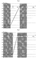
- the module 30 sends a torque instruction to the module 40 as represented by example on the figure 2 .
- the ordinate axis represents the torque setpoint as a percentage of the maximum torque Cmax.
- the negative percentages which represent a negative torque, correspond to an operating mode in the generator of the electric machine 53.
- the reversible converter 50 then supplies electrical energy to recharge the electric storage unit 11.
- the positive percentages on the ordinate axis correspond to a motor mode operation of the electric machine 53.
- the reversible converter 50 then absorbs electrical energy from the electrical storage unit 11 to convert it into mechanical energy so as to lower the charge level in the electric storage unit 11.
- the module 30 having mainly the function of controlling the charge level of the electric storage unit 11, called SOC (acronym for State of Charge in a foreign language), it is not represented here the percentages of torque going beyond 10%.
- the electrical storage can be used between 30 and 90% SOC.
- the storer When the storer is lightly loaded, the charging of the electric machine is done with high torque. When the storer is well loaded, the recharge is made with increasingly weaker couples.
- the useful energy of the storer is important, only the recovery in deceleration or slope, is used to recharge the storer so as not to saturate it.
- the torque setpoint is progressively changed from -80% to 0% when the level of load has reached 70%.
- the 70% to 90% load level area which is marked with rising hatch, is strictly reserved for deceleration recovery. This zone is large enough that no deceleration energy is lost, except on a very long slope. Finally, the area from 90% to 100% again with descending hatching is prohibited to keep a safety margin so as not to saturate the electrical storage.
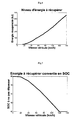
- the invention comes into play to ensure that the kinetic energy of the vehicle can always be stored in the battery or in the super capacitances of the electric storage unit 11, during deceleration by allowing maintenance of the electric braking performance.
- the energy that can still be recovered in the storer must be at least equal to the energy recovered during a deceleration until the vehicle stops.
- the energy level to be recovered is represented as a function of a speed of vehicle from 0 to 140 km / h.
- the speed is represented on the abscissa.
- the ordinate shows the recoverable energy in kilojoules which, given the weight and load of a vehicle taken as an example, changes from 0 to 500 kilojoules.
- the curve is of substantially parabolic pace because one knows that the kinetic energy is proportional to the square of the speed.
- the various forces of aerodynamic friction or hydraulic braking have been considered here.
- the ordinate shows the charge level SOC not to be exceeded as a function of the speed of the vehicle in kilometers, reported in abscissae from 0 to 140.
- the curve is substantially symmetrical to that represented on FIG. figure 4 , because the recovered energy, converted into SOC, corresponds to the distance which separates the high limit (here 60%) of the point on the curve.
- the charge level of the electric storage unit 11 is preferably equal to 60% because little kinetic energy of the vehicle will be recovered during braking.
- a charge level of the electrical storage unit is recommended at 40%, so as to leave 20% of overload available to reach 60%.
- the 20% of charge available correspond to the kinetic energy to recover converted into charge level in the storage.
- the load level should not exceed two-thirds above 70 km / h and the load level should be as low as possible above 120 km / h. This curve establishes the target load level that should not be exceeded.
- the electrical machine is controlled so as to continue recharging the electrical storage unit by taking the engine torque according to the level of the engine. charge. This results in a charging strategy that takes into account the load and kinetic energy of the vehicle through its speed.
- the electrical machine takes torque until this level is reached. If the load of the storer is higher than the target load level, the electrical machine no longer draws any torque.
- the load of the storer gradually decreases as the various levies of the system represented by block 21 on the figure 1 and which include auxiliaries, transmission or increases in performance of the engine. Sometimes this gradual discharge of the storer may be too slow and if a deceleration occurs before the target load level is reached, some of the kinetic energy may be lost. This is why, advantageously, the means that we will explain now further cause a load shedding of the heat engine.
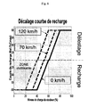
- the objective is to reach the target load level more quickly and to benefit as soon as possible from the energies available when the sum of the electric storage load and the recoverable kinetic energy is greater than what can be stored in the electric storage unit.
- the negative ordinates correspond as before, to the recharge torque Mel as a percentage of the maximum torque Cmax.
- the level of charge not to be exceeded is 60%.
- the charge level is between 40% and 60%, it is advisable to ask for a torque that changes from -80% to 0% until reaching the level of 60%.
- the curve corresponding to 0 km / h is shifted to the left of so that the null torque reference corresponds to a load level of 53%.
- the curve is shifted to the left so as to request a zero torque setpoint at 0% when the load of the storer is at 40% for a speed of 120 km / h.
- the curve previously explained is extended to a point whose abscissa corresponds to the level of load observed and the ordinate then corresponds to a positive torque setpoint to unload the energy store until it returns to the appropriate load level for the speed found on the abscissa axis.
- the previously explained curves which shifted to the left in the part of the plane of the negative ordinates corresponding to a recharge, are each extended to the right in the part of the plane of the positive ordinates which correspond to a load shedding of the energy store.
- the load shedding is materialized by a positive torque supply of the electric machine without seeking improvement in the performance of the engine. This shedding torque, then used to contribute to the traction of the vehicle relieves the engine and contributes to a reduction of fuel consumption.
- the module 3 executes steps to implement the method according to the invention, starting from an initial step 300.
- the module 3 is arranged to receive a vehicle speed, measured for example from a tachogenerator dynamo not shown.
- the measured speed validates a transition 301 which activates a step 302 in which the module 3 uses the measured speed value to access a corresponding load curve, either by a calculation or by pointing in a memory on one of the curves. represented in figure 6 .
- the load measured from the sensor 31 validates a transition 303 which activates a step 304 in which a torque setpoint is determined as being the ordinate of the curve selected in the preceding step which corresponds to the point whose abscissa has value the measured load. This torque setpoint is sent to module 4.
- module 4 executes process steps according to the invention from an initial step 400.
- a step 402 is activated by validation of a transition 401 which notes a lack of priority control.
- a priority command is for example a regenerative braking command or a starting command of the engine.
- a lighting control or various accessories is not in itself a priority control.
- the module 4 applies the torque instruction received from the module 3 to the converter 50.
- the module 4 returns to the initial step 400 when a priority control detection validates a transition 403. It goes without saying that the modules 3 and 4 can be indifferently in two different electronic circuits or together in the same electronic circuit.
- the means can be adapted for the protection of the saturation of the storer by potential energy related to the altitude.
- the energies at stake are not the same because the kinetic energy is finite (speed limitation) whereas the potential energy is much less (mountain).
- the electrical storage unit 11 is not limited to a battery or supercapacitors, the invention operates with any type of electrical storage technology.
- the operation of the hybrid vehicle in pure electric driving or not, does not affect the invention which relates to the recharging of the storer, and incidentally on its load shedding.
Landscapes
- Engineering & Computer Science (AREA)
- Transportation (AREA)
- Mechanical Engineering (AREA)
- Power Engineering (AREA)
- Chemical & Material Sciences (AREA)
- Combustion & Propulsion (AREA)
- Life Sciences & Earth Sciences (AREA)
- Sustainable Development (AREA)
- Sustainable Energy (AREA)
- Automation & Control Theory (AREA)
- Electric Propulsion And Braking For Vehicles (AREA)
Applications Claiming Priority (1)
| Application Number | Priority Date | Filing Date | Title |
|---|---|---|---|
| FR0852057A FR2929218B1 (fr) | 2008-03-28 | 2008-03-28 | Procede et dispositif de controle d'une charge electrique |
Publications (2)
| Publication Number | Publication Date |
|---|---|
| EP2105366A2 true EP2105366A2 (de) | 2009-09-30 |
| EP2105366A3 EP2105366A3 (de) | 2016-07-27 |
Family
ID=39971129
Family Applications (1)
| Application Number | Title | Priority Date | Filing Date |
|---|---|---|---|
| EP09155954.2A Withdrawn EP2105366A3 (de) | 2008-03-28 | 2009-03-24 | Verfahren und Vorrichtung zur Kontrolle einer elektrischen Ladung |
Country Status (2)
| Country | Link |
|---|---|
| EP (1) | EP2105366A3 (de) |
| FR (1) | FR2929218B1 (de) |
Cited By (2)
| Publication number | Priority date | Publication date | Assignee | Title |
|---|---|---|---|---|
| FR3079802A1 (fr) * | 2018-04-09 | 2019-10-11 | Psa Automobiles Sa | Systeme de commande pour vehicule hybride |
| US11390283B2 (en) * | 2019-07-25 | 2022-07-19 | Ford Global Technologies, Llc | System and method for controlling vehicle during coast |
Families Citing this family (1)
| Publication number | Priority date | Publication date | Assignee | Title |
|---|---|---|---|---|
| CN113320521B (zh) * | 2020-02-28 | 2022-10-04 | 联合汽车电子有限公司 | 混动交通工具的速度规划方法及系统 |
Citations (1)
| Publication number | Priority date | Publication date | Assignee | Title |
|---|---|---|---|---|
| WO2006018695A1 (en) | 2004-08-13 | 2006-02-23 | Eaton Corporation | Battery control system for hybrid vehicle and method for controlling a hybrid vehicle battery |
Family Cites Families (4)
| Publication number | Priority date | Publication date | Assignee | Title |
|---|---|---|---|---|
| JP3300294B2 (ja) * | 1998-12-07 | 2002-07-08 | 本田技研工業株式会社 | ハイブリッド車両の制御装置 |
| JP2001268719A (ja) * | 2000-03-23 | 2001-09-28 | Toyota Motor Corp | ハイブリッド車両のバッテリ充電制御装置 |
| US6304055B1 (en) * | 2000-06-30 | 2001-10-16 | Ford Global Technologies, Inc. | Method and apparatus for efficiently operating a hybrid vehicle |
| DE102005016300A1 (de) * | 2005-04-08 | 2006-10-12 | Proton Motor Fuel Cell Gmbh | Antriebssystem und Verfahren zum Betrieb eines Antriebssystems für ein elektrisch betriebenes Fahrzeug |
-
2008
- 2008-03-28 FR FR0852057A patent/FR2929218B1/fr active Active
-
2009
- 2009-03-24 EP EP09155954.2A patent/EP2105366A3/de not_active Withdrawn
Patent Citations (1)
| Publication number | Priority date | Publication date | Assignee | Title |
|---|---|---|---|---|
| WO2006018695A1 (en) | 2004-08-13 | 2006-02-23 | Eaton Corporation | Battery control system for hybrid vehicle and method for controlling a hybrid vehicle battery |
Cited By (2)
| Publication number | Priority date | Publication date | Assignee | Title |
|---|---|---|---|---|
| FR3079802A1 (fr) * | 2018-04-09 | 2019-10-11 | Psa Automobiles Sa | Systeme de commande pour vehicule hybride |
| US11390283B2 (en) * | 2019-07-25 | 2022-07-19 | Ford Global Technologies, Llc | System and method for controlling vehicle during coast |
Also Published As
| Publication number | Publication date |
|---|---|
| FR2929218A1 (fr) | 2009-10-02 |
| FR2929218B1 (fr) | 2010-05-07 |
| EP2105366A3 (de) | 2016-07-27 |
Similar Documents
| Publication | Publication Date | Title |
|---|---|---|
| EP2195185B1 (de) | Verfahren zum antreiben eines hybrid-antriebszuges auf basis eines batterieladestatus | |
| EP1588889B1 (de) | Elektrische Antriebsanlage für Brennstoffzellenfahrzeug mit einem elektrischen Widerstand zur Wärmeabfuhr | |
| EP1589601B1 (de) | Elektrisches Betriebssystem für ein Fahrzeug, mit dissipativem elektrischem Widerstand gekühlt mit Kühlflussigkeit | |
| EP2715909B1 (de) | Verfahren zur wiederaufladung eines fahrzeugbatteriepaares mit unterschiedlichen nennspannungen und zugehöriges system | |
| EP2885147B1 (de) | Verfahren zur begrenzung des drehmoments einer elektrischen maschine eines hybridfahrzeugs mit einer drehzahlregelungssystem | |
| EP2788221B1 (de) | Verfahren zur verwaltung eines alternators, der mit mindestens einer hochleistungsbatterie kombiniert, und von einer wärmekraftmaschine betrieben ist | |
| FR3003705A1 (fr) | Reseau de bord de vehicule automobile et son procede de gestion ainsi que des moyens d'implementation du procede | |
| EP3237258A1 (de) | Verfahren zur energieverwaltung einer wiederaufladbaren traktionsbatterie eines hybridfahrzeugs | |
| EP2105366A2 (de) | Verfahren und Vorrichtung zur Kontrolle einer elektrischen Ladung | |
| FR3058116A1 (fr) | Vehicule capable d'arreter et de demarrer automatiquement un moteur. | |
| EP2326541A1 (de) | Verfahren und vorrichtung zur überwachung eines hybridfahrzeug-energiespeichersystems | |
| FR2983435A1 (fr) | Procede de gestion de l'energie electrique d'un vehicule automobile et vehicule automobile mettant en oeuvre un tel procede | |
| FR2931427A1 (fr) | Procede de decouplage d'une machine electrique de traction sur un vehicule hybride et vehicule hybride pour la mise en oeuvre du procede | |
| EP2112739A1 (de) | Verfahren zur Begrenzung der inneren Erwärmung eines Super-Kondensators | |
| EP2113435B1 (de) | Verfahren und Vorrichtung zur Steuerung eines Energiespeichers für ein Hybridfahrzeug | |
| EP2108558B1 (de) | Verfahren und Vorrichtung zur Kontrolle einer energetischen Belastung | |
| WO2009044073A2 (fr) | Systeme de commande pour la gestion de l'energie electrique transitant par un element de stockage dans un groupe motopropulseur hybride equipe d'une transmission infiniment variable | |
| FR2995859A1 (fr) | Pilotage du mode de traction d'un vehicule hybride | |
| FR3078204A1 (fr) | Gestion de l’energie electrique dans un vehicule automobile hybride | |
| EP1674328A1 (de) | Hybridantriebssteuersystem für ein Fahrzeug | |
| JP2023149390A (ja) | 車両、および制御方法 | |
| WO2025131793A1 (fr) | Procédé et dispositif pour gérer la mise en œuvre d'une fonction de freinage d'un véhicule électrique au moyen d'un système de freinage redondant | |
| WO2020157394A1 (fr) | Procede de pilotage d'un generateur couple a une roue-libre d'un vehicule automobile | |
| EP4222009A1 (de) | Vorrichtung zur steuerung des neustarts eines verbrennungsmotors eines hybridfahrzeugs | |
| FR3120698A1 (fr) | Procede de detection d’un etat de masse excessive d’un vehicule automobile et methode de gestion de la charge d’une batterie de traction |
Legal Events
| Date | Code | Title | Description |
|---|---|---|---|
| PUAI | Public reference made under article 153(3) epc to a published international application that has entered the european phase |
Free format text: ORIGINAL CODE: 0009012 |
|
| AK | Designated contracting states |
Kind code of ref document: A2 Designated state(s): AT BE BG CH CY CZ DE DK EE ES FI FR GB GR HR HU IE IS IT LI LT LU LV MC MK MT NL NO PL PT RO SE SI SK TR |
|
| AX | Request for extension of the european patent |
Extension state: AL BA RS |
|
| PUAL | Search report despatched |
Free format text: ORIGINAL CODE: 0009013 |
|
| AK | Designated contracting states |
Kind code of ref document: A3 Designated state(s): AT BE BG CH CY CZ DE DK EE ES FI FR GB GR HR HU IE IS IT LI LT LU LV MC MK MT NL NO PL PT RO SE SI SK TR |
|
| AX | Request for extension of the european patent |
Extension state: AL BA RS |
|
| RIC1 | Information provided on ipc code assigned before grant |
Ipc: H02J 7/14 20060101ALI20160617BHEP Ipc: B60W 20/00 20160101AFI20160617BHEP Ipc: B60W 10/26 20060101ALN20160617BHEP Ipc: B60W 10/08 20060101ALN20160617BHEP Ipc: B60L 7/10 20060101ALI20160617BHEP Ipc: B60L 11/18 20060101ALI20160617BHEP |
|
| AKY | No designation fees paid | ||
| AXX | Extension fees paid |
Extension state: AL Extension state: RS Extension state: BA |
|
| REG | Reference to a national code |
Ref country code: DE Ref legal event code: R108 |
|
| STAA | Information on the status of an ep patent application or granted ep patent |
Free format text: STATUS: THE APPLICATION IS DEEMED TO BE WITHDRAWN |
|
| 18D | Application deemed to be withdrawn |
Effective date: 20170128 |