EP2017455B1 - AGR-Kühlvorrichtung - Google Patents
AGR-Kühlvorrichtung Download PDFInfo
- Publication number
- EP2017455B1 EP2017455B1 EP07253105A EP07253105A EP2017455B1 EP 2017455 B1 EP2017455 B1 EP 2017455B1 EP 07253105 A EP07253105 A EP 07253105A EP 07253105 A EP07253105 A EP 07253105A EP 2017455 B1 EP2017455 B1 EP 2017455B1
- Authority
- EP
- European Patent Office
- Prior art keywords
- egr cooler
- partition
- bottom portion
- flat tubes
- opening
- Prior art date
- Legal status (The legal status is an assumption and is not a legal conclusion. Google has not performed a legal analysis and makes no representation as to the accuracy of the status listed.)
- Ceased
Links
- 238000005192 partition Methods 0.000 claims description 33
- UGFAIRIUMAVXCW-UHFFFAOYSA-N Carbon monoxide Chemical compound [O+]#[C-] UGFAIRIUMAVXCW-UHFFFAOYSA-N 0.000 claims description 14
- 239000003546 flue gas Substances 0.000 claims description 13
- 239000000498 cooling water Substances 0.000 claims description 7
- 230000000149 penetrating effect Effects 0.000 claims description 3
- 238000005219 brazing Methods 0.000 description 3
- 230000037431 insertion Effects 0.000 description 2
- 238000003780 insertion Methods 0.000 description 2
- 230000035515 penetration Effects 0.000 description 2
- 125000006850 spacer group Chemical group 0.000 description 2
- 238000001816 cooling Methods 0.000 description 1
- 239000007789 gas Substances 0.000 description 1
- 238000009434 installation Methods 0.000 description 1
- 230000002093 peripheral effect Effects 0.000 description 1
- 230000002787 reinforcement Effects 0.000 description 1
- 238000004781 supercooling Methods 0.000 description 1
Images
Classifications
-
- F—MECHANICAL ENGINEERING; LIGHTING; HEATING; WEAPONS; BLASTING
- F02—COMBUSTION ENGINES; HOT-GAS OR COMBUSTION-PRODUCT ENGINE PLANTS
- F02M—SUPPLYING COMBUSTION ENGINES IN GENERAL WITH COMBUSTIBLE MIXTURES OR CONSTITUENTS THEREOF
- F02M37/00—Apparatus or systems for feeding liquid fuel from storage containers to carburettors or fuel-injection apparatus; Arrangements for purifying liquid fuel specially adapted for, or arranged on, internal-combustion engines
- F02M37/0011—Constructional details; Manufacturing or assembly of elements of fuel systems; Materials therefor
- F02M37/0023—Valves in the fuel supply and return system
- F02M37/0029—Pressure regulator in the low pressure fuel system
-
- F—MECHANICAL ENGINEERING; LIGHTING; HEATING; WEAPONS; BLASTING
- F02—COMBUSTION ENGINES; HOT-GAS OR COMBUSTION-PRODUCT ENGINE PLANTS
- F02M—SUPPLYING COMBUSTION ENGINES IN GENERAL WITH COMBUSTIBLE MIXTURES OR CONSTITUENTS THEREOF
- F02M26/00—Engine-pertinent apparatus for adding exhaust gases to combustion-air, main fuel or fuel-air mixture, e.g. by exhaust gas recirculation [EGR] systems
- F02M26/13—Arrangement or layout of EGR passages, e.g. in relation to specific engine parts or for incorporation of accessories
- F02M26/22—Arrangement or layout of EGR passages, e.g. in relation to specific engine parts or for incorporation of accessories with coolers in the recirculation passage
- F02M26/29—Constructional details of the coolers, e.g. pipes, plates, ribs, insulation or materials
- F02M26/32—Liquid-cooled heat exchangers
-
- F—MECHANICAL ENGINEERING; LIGHTING; HEATING; WEAPONS; BLASTING
- F28—HEAT EXCHANGE IN GENERAL
- F28D—HEAT-EXCHANGE APPARATUS, NOT PROVIDED FOR IN ANOTHER SUBCLASS, IN WHICH THE HEAT-EXCHANGE MEDIA DO NOT COME INTO DIRECT CONTACT
- F28D9/00—Heat-exchange apparatus having stationary plate-like or laminated conduit assemblies for both heat-exchange media, the media being in contact with different sides of a conduit wall
- F28D9/0062—Heat-exchange apparatus having stationary plate-like or laminated conduit assemblies for both heat-exchange media, the media being in contact with different sides of a conduit wall the conduits for one heat-exchange medium being formed by spaced plates with inserted elements
- F28D9/0068—Heat-exchange apparatus having stationary plate-like or laminated conduit assemblies for both heat-exchange media, the media being in contact with different sides of a conduit wall the conduits for one heat-exchange medium being formed by spaced plates with inserted elements with means for changing flow direction of one heat exchange medium, e.g. using deflecting zones
-
- F—MECHANICAL ENGINEERING; LIGHTING; HEATING; WEAPONS; BLASTING
- F28—HEAT EXCHANGE IN GENERAL
- F28F—DETAILS OF HEAT-EXCHANGE AND HEAT-TRANSFER APPARATUS, OF GENERAL APPLICATION
- F28F27/00—Control arrangements or safety devices specially adapted for heat-exchange or heat-transfer apparatus
- F28F27/02—Control arrangements or safety devices specially adapted for heat-exchange or heat-transfer apparatus for controlling the distribution of heat-exchange media between different channels
-
- F—MECHANICAL ENGINEERING; LIGHTING; HEATING; WEAPONS; BLASTING
- F28—HEAT EXCHANGE IN GENERAL
- F28F—DETAILS OF HEAT-EXCHANGE AND HEAT-TRANSFER APPARATUS, OF GENERAL APPLICATION
- F28F3/00—Plate-like or laminated elements; Assemblies of plate-like or laminated elements
- F28F3/02—Elements or assemblies thereof with means for increasing heat-transfer area, e.g. with fins, with recesses, with corrugations
- F28F3/025—Elements or assemblies thereof with means for increasing heat-transfer area, e.g. with fins, with recesses, with corrugations the means being corrugated, plate-like elements
-
- F—MECHANICAL ENGINEERING; LIGHTING; HEATING; WEAPONS; BLASTING
- F28—HEAT EXCHANGE IN GENERAL
- F28F—DETAILS OF HEAT-EXCHANGE AND HEAT-TRANSFER APPARATUS, OF GENERAL APPLICATION
- F28F3/00—Plate-like or laminated elements; Assemblies of plate-like or laminated elements
- F28F3/02—Elements or assemblies thereof with means for increasing heat-transfer area, e.g. with fins, with recesses, with corrugations
- F28F3/04—Elements or assemblies thereof with means for increasing heat-transfer area, e.g. with fins, with recesses, with corrugations the means being integral with the element
- F28F3/042—Elements or assemblies thereof with means for increasing heat-transfer area, e.g. with fins, with recesses, with corrugations the means being integral with the element in the form of local deformations of the element
- F28F3/044—Elements or assemblies thereof with means for increasing heat-transfer area, e.g. with fins, with recesses, with corrugations the means being integral with the element in the form of local deformations of the element the deformations being pontual, e.g. dimples
-
- F—MECHANICAL ENGINEERING; LIGHTING; HEATING; WEAPONS; BLASTING
- F28—HEAT EXCHANGE IN GENERAL
- F28D—HEAT-EXCHANGE APPARATUS, NOT PROVIDED FOR IN ANOTHER SUBCLASS, IN WHICH THE HEAT-EXCHANGE MEDIA DO NOT COME INTO DIRECT CONTACT
- F28D21/00—Heat-exchange apparatus not covered by any of the groups F28D1/00 - F28D20/00
- F28D21/0001—Recuperative heat exchangers
- F28D21/0003—Recuperative heat exchangers the heat being recuperated from exhaust gases
-
- F—MECHANICAL ENGINEERING; LIGHTING; HEATING; WEAPONS; BLASTING
- F28—HEAT EXCHANGE IN GENERAL
- F28F—DETAILS OF HEAT-EXCHANGE AND HEAT-TRANSFER APPARATUS, OF GENERAL APPLICATION
- F28F2250/00—Arrangements for modifying the flow of the heat exchange media, e.g. flow guiding means; Particular flow patterns
- F28F2250/06—Derivation channels, e.g. bypass
Definitions
- the present invention relates to an EGR (exhaust gas recirculation) cooler.
- An EGR cooler is proposed by the Patent Document 1 given below.
- a plurality of flat tubes is arranged in parallel, and both ends thereof penetrate through the respective header plates, thus structuring a core.
- a casing encloses the outer circumferential surface of the core to form a cooler body.
- a bypass pipe is laid along the cooler body. The bypass pipe and one end of the cooler body are connected via a tank, while the other end of the cooler body and the bypass pipe are connected to a tank having a gate valve.
- Document EP 1355058 discloses an EGR cooler comprising a core of bent tubes arranged in parallel, a header plate, the outer circumferential surface of said core being enclosed in a casing, further comprising a tank body and a partition, the flue gas being introduced to one side of said partition in each of the flat tubes, and then takes a U-turn at the bottom position to flow out from the other side of the partition, while a cooling water is introduced into said casing.
- the present invention may provide a compact EGR cooler integrated with a bypass valve with a with a small number of parts.
- An aspect of the present invention provides an EGR cooler having the structure of: a plurality of flat tubes (1), each having a bottom portion (1a) closing one end thereof, having an opening (1b) at the other end thereof, being arranged in parallel facing flat face thereeach; corrugated fins (2) formed in each of the flat tubes (1) while keeping a space (1c) against the bottom portion (1a) so as a ridgeline (2a) of each of the corrugated fins (2) to extend from the opening (1b) to the bottom portion (1a) ; a header plate (3) to which the opening (1b) of each of the flat tubes (1) penetrates therethrough and is fixed thereto, and a core (4) formed by the flat tubes, corrugated fins and header plate, wherein: the outer circumferential surface of the core (4) is enclosed by a casing (5); the header plate (3) closes an open end of a tank body (7) equipped with a partition (6); and the partition (6) is located at an intermediate position in the width direction of the opening (1b) of each of the flat tubes
- the EGR cooler further has an elastic support (11) which supports outer circumferential surface of the bottom portion (1a) of each of the flat tubes (1) at one end portion thereof, while the other end portion thereof is attached to the casing (5).
- the casing (5) may have a concave portion (21) at an intermediate position of the bottom portion thereof, and the other end portion of the elastic support (11) may be fitted into the concave portion (21).
- the partition (6) may have a connection opening (6a) which is closed by a bypass valve (8) capable of being arbitrarily closed or opened.
- each of the flat tubes (1) penetrating through the header plate (3) has a notched portion (25), at an intermediate position of an edge thereof in the width direction, cut to the face of the header plate (3), and an edge of the partition (6) contacts with the notched portion (25).
- the header plate (3) has a protruded strip (3a) at a position facing an edge of the partition (6) so as the protruded strip (3a) and an edge of each of the flat tubes (1) to become flush with each other, and the edge of the partition (6) contacts with the protruded strip (3a).
- the outer circumferential surface of the bottom portion (1a) of the flat tube (1) may be formed in an arc shape, auxiliary fins (2b) may be arranged at the bottom portion (1a), and the bottom portion (1a) and the auxiliary fins (2b) may be brazed to fix them together.
- the flat tube (1) may be a brazed article structured by a pair of plates (29) and (30), having the respective side walls (29a) and (30a), erecting at the periphery thereof except at the opening of flat tube (1), while the side walls (29a) and (30a) may have the respective concave portions (29b) and (30b) at the respective matching positions thereeach, thus fitting the concave portions (29b) and (30b) thereeach.
- corrugated fins 2 are located in the flat tube 1 having the bottom portion 1a, and the opening 1b of each of the plurality of flat tubes 1 penetrates to fix to the header plate 3, thereby forming the core 4.
- the outer circumferential surface of the core 4 is enclosed by the casing 5.
- the header plate 3 closes the opening at an end of the tank body 7 provided with the partition 6. Since the partition 6 is located at an intermediate position in the width direction of the opening 1b of the flat tube 1, the number of parts may be small and the structure may be quite simple, thus providing a U-turn flow compact EGR cooler at a low cost.
- Embodiments which locate the elastic support 11 between the bottom portion 1a of each flat tube 1 and the casing 5 may assist in smoothly absorbing the thermal expansion of the EGR cooler in operating state, while the elastic support 11 always supports each flat tube 1, thus providing a high strength EGR cooler enduring vibrations and other mechanical disturbances.
- Embodiments which form the concave portion 21 at an intermediate position at the bottom portion of the casing 5 and which fits other edge portion of the elastic support 11 to the concave portion 21 may provide a highly reliable EGR cooler with readily installation.
- Embodiments which have the connection opening (6a) on the partition (6) and which close the connection opening (6a) with the arbitrarily closing and opening bypass valve (8) may allow the flue gas to bypass the flat tube (1) by opening the bypass valve (8), at a low flue gas temperature, thus preventing supercooling of the flue gas.
- Embodiments which have the notched portion 25, at an intermediate position in the width direction of an edge of the flat tube 1 penetrating through the header plate 3, thus making an edge of the partition 6 contact with the notched portion 25, may provide a compact EGR cooler with simple structure free of leakage.
- Embodiments which have the protruded strip 3a on the header plate 3 to make an edge of the partition 6 contact with the protruded strip 3a may provide a highly reliable EGR cooler with simple structure and improved air-tightness of the partition 6.
- the face outer circumference of the bottom portion (1a) of the flat tube (1) may be formed in an arc shape
- the auxiliary fins (2b) may be arranged on the bottom portion (1a)
- the bottom portion (1a) and the auxiliary fins (2b) may be brazed to fix them together.
- the pressure strength of the bottomportion (1a) of the flat tube (1) can be increased.
- the flat tube (1) may be formed by a brazed article structured by combining a pair of plates (29) and (30) having the respective side walls (29a) and (30a) erecting at the periphery thereeach except at the opening of flat tube (1), and that the concave portions (29b) and (30b) may be formed on the respective side walls (29a) and (30a) at the matching position thereeach, thus fitting the concave portions (29b) and (30b) thereeach.
- the pair of plates (29) and (30) may be prevented from misalignment in the flat direction thereof, thus providing a highly reliable EGR cooler.
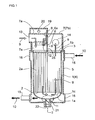
- Fig. 1 shows a vertical cross section of an EGR cooler according to the present invention
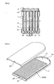
- Fig. 2 shows the cross sectional view along II-II line in Fig. 1
- Fig. 3 shows an exploded perspective view of the flat tube 1 having the corrugated fins 2
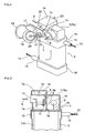
- Fig. 4 shows a perspective appearance of the EGR cooler.
- the EGR cooler has a plurality of flat tubes 1 arranged in parallel facing the flat face thereof each other, and the opening 1b of each flat tube 1 penetrates through and fixes to the header plate 3, thus forming the core 4.
- the casing 5 encloses the outer circumferential surface of the core 4, and the header plate 3 closes the opening at an end of the tank body 7 equipped with the partition 6.
- each flat tube 1 is formed by a pair of plates.
- the peripheral portion of each plate erects except an end in the longitudinal direction thereof. Both plates are fitted with each other, and the fitted portion is brazed or welded to fix them together.
- On outer face of the flat tube there are a large number of dimples for spacer (not shown).
- Each flat tube 1 has the bottom portion 1a in flat arc shape, and has the corrugated fins 2 inside thereof except in the bottom portion 1a.
- the ridgeline 2a on each of the corrugated fins 2 extends from the opening 1b to the bottom portion 1a.
- the corrugated fins 2 have a flat face at rise portion and at down portion of each fin, and there exists no louver such as cut-louver. With the configuration, the flue gas flowing through the inside space of the fin is prevented from moving in the width direction of the flat tube 1.
- the notched portion 25 is formed at an intermediate position in the width direction at an edge of the opening 1b of each flat tube 1, (although the position in this example is at the center of the width direction, the present invention does not limit the position to the center in the width direction).
- the flat tube 1 configured as above is inserted into a tube penetration hole (not shown) in the header plate 3, and the inserted flat tube 1 and the header plate 3 are fixed by brazing or other means at the penetration portion, thus forming the core 4.
- the bottom of the notched portion 25 of each flat tube 1 is positioned to become flush with the face of the header plate 3.
- the casing 5 is enclosed to the outer circumferential surface of the core 4.
- the casing 5 has an annular expanded portion 16 which slightly expands outward at each end in the longitudinal direction thereof. To each of both annular expanded portions 16, an inlet/outlet pipe 15 penetrates to fix them together. At the bottom portion of the annular expanded portion 16 of the casing 5, a concave portion 21 is formed. One end of the elastic support 11 is fitted to fix to the concave portion 21 via a bracket 22. As illustrated in Fig. 2 , the other end of the elastic support 11 enters into each space between the bottom portions 1a of the flat tubes 1, thus supporting the outer circumferential surface of the bottom portion 1a of each flat tube 1.
- the header plate 3 closes an end opening of the tank body 7.
- the tank body 7 has the partition 6 at an intermediate position thereof to divide the inside space thereof into an inlet tank portion 7a and an outlet tank portion 7b. That is, the edge of the partition 6 contacts to fix with the header plate 3 at the position of the notched portion 25 of each flat tube 1.
- the partition 6 has the connection opening 6a, and the connection opening 6a is closed by the bypass valve 8 capable of being arbitrarily closed or opened. In concrete terms, the bypass valve 8 moves from the position of the solid line to the position of broken line.
- a rotary shaft 12 of the bypass valve 8 protrudes outward from the tank body 7, as shown in Fig. 4 , and the front end of the rotary shaft 12 is fixed to one end of a first link 23.
- one end of a second link 26 is fixed, while the other end of the second link 26 penetrates through an actuator 18.
- the actuator 18 drives a second link 26 in a state of arbitrarily extending and retracting using a controller 17, thus rotating the rotary shaft 12 via the first link 23 to move the bypass valve 8 from the position of solid line to the position of broken line in Fig. 1 , as described above.
- the bypass valve 8 can be held at an intermediate position between the solid line one and the broken line one.
- the controller 17 according to the example generates a negative pressure when the flue gas temperature is relatively low, and the generated negative pressure enters the actuator 18 via a connection pipe 24, thus driving the second link 26 to open the bypass valve 8.
- the tank body 7 is divided by the partition 6 into the inlet tank portion 7a and the outlet tank portion 7b, while an auxiliary tank 19 is fitted to outer circumferential surface of the inlet tank portion 7a.
- an auxiliary tank 19 is fitted to outer circumferential surface of the inlet tank portion 7a.
- the cooling water is supplied to the auxiliary tank 19, thus cooling the outer circumferential surface of the inlet tank portion 7a.
- the cooling water 10 enters the casing 5 through one inlet/outlet pipe 15 to cool the outer circumferential surface of each flat tube 1, then flows out from other inlet/outlet pipe 15.
- the high temperature flue gas 9 flows through one side in the width direction of each flat tube 1, entering from an inlet 13 of the inlet tank portion 7a. Then, the flue gas takes a U-turn in a space 1c of the bottom portion 1a to flow through the other side in the width direction of the flat tube 1. After that, the flue gas flows out from the outlet pipe 14 of the outlet tank portion 7b. As a result, heat is exchanged between the cooling water 10 and the flue gas 9. During the heat exchange, the flat tube 1 extends, caused by the thermal expansion, relative to the casing 5 because the flue gas 9 flows inside the flat tube 1. The thermal expansion is, however, absorbed by the deformation of the elastic support 11. In addition, as illustrated in Fig. 2 , the elastic support 11 holds the bottom portion 1a of each flat tube 1, thereby absorbing the vibrations and other mechanical disturbances during operation to protect the brazed portion of the flat tube 1.
- the above bypass valve 8 may be eliminated. In that case, the connection opening 6a of the partition 6 is not required.
- Fig. 5 shows another example of the EGR cooler of the present invention.
- the only difference from the EGR cooler in Fig. 1 is the shape of the header plate 3.
- the edge of the partition 6 is inserted into the notched portion 25 of each flat tube 1, and the edge thereof is formed to contact with the header plate 3.
- the example of Fig. 5 has the protruded strip 3a at an intermediate position in the width direction of the header plate 3, and the edge of the protruded strip 3a becomes flush with the opening 1b of the flat tube 1.
- the protruded strip 3a is brought into contact and fixed together with the edge of the partition 6 using brazing or other means.
- the inlet tank portion 7a and the outlet tank portion 7b are perfectly separated from each other.
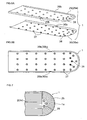
- Fig. 6 shows still another example of the flat tube 1 applied in the EGR cooler of the present invention.
- Fig. 6 (A) shows an exploded perspective view of the flat tube
- Fig. 6(B) shows the plan view of the assembled one.
- the flat tube 1 is formed by press-forming, and has a combination of a pair of plates 29 and 30, having the respective side walls 29a and 30a erecting at the periphery thereof except at the opening thereof, and has the respective concave portions 29b and 30b, matching with each other, on the respective side walls 29a and 30a.
- the pair of plates 29 and 30 is combined together, and the concave portions 29b and 30b are fitted each other, thereby preventing from misalignment of the plates in the face direction.
- the insertion portion and the contact portion of each of the plates 29 and 30 are brazed to fix together.
- the dimples 27 on a flat tube 1 contact with the dimples 27 on adjacent flat tube 1 at the respective positions thereof.
- Fig. 7 shows a further example of the flat tube 1 applied in the EGR cooler of the present invention.
- corrugated fins 2 having the respective straight ridgelines 2a.
- auxiliary fins 2b At the bottom portion 1a in a flat semicircular shape, there are arranged auxiliary fins 2b.
- Each of the fins 2 and 2b, and the inside face of the plates 29 and 30 are brazed to fix them together.
- the auxiliary fins 2b are formed so as the ridgeline of each fin to become arc shape.
- auxiliary fins 2b are not necessarily limited to the above example, and there may be used offset fins which have corrugated shape having cut-louvers on rise and down faces of each fin. In that case, the total outer circumference of the fin can be formed in semicircular shape.
Landscapes
- Engineering & Computer Science (AREA)
- Mechanical Engineering (AREA)
- General Engineering & Computer Science (AREA)
- Physics & Mathematics (AREA)
- Thermal Sciences (AREA)
- Chemical & Material Sciences (AREA)
- Combustion & Propulsion (AREA)
- Heat-Exchange Devices With Radiators And Conduit Assemblies (AREA)
- Exhaust-Gas Circulating Devices (AREA)
Claims (7)
- AGR-Kühler, der Folgendes umfasst:eine Vielzahl flacher Rohre (1), die jeweils einen Bodenabschnitt (1a) aufweisen, der ein Ende von diesen verschließt, und die eine Öffnung (1 b) an ihrem anderen Ende aufweisen, wobei die Rohre parallel angeordnet sind und einander mit der flachen Fläche zugewandt sind;gewellte Rippen (2), die in den flachen Rohren (1) so ausgebildet sind, dass sich die Kammlinie jeder gewellten Rippe von der Öffnung zu dem Bodenabschnitt erstreckt;eine Kopfplatte (3), durch welche die Öffnung der flachen Rohre hindurchverläuft und an der diese befestigt ist, undeinen Kern (4), der durch die flachen Rohre, die gewellten Rippen und die Kopfplatte gebildet ist, wobeidie Außenumfangsoberfläche des Kerns durch ein Gehäuse (5) eingeschlossen ist;die Kopfplatte ein offenes Ende eines Tankkörpers verschließt, der mit einem Trennelement versehen ist; unddas Trennelement in einer mittleren Position in der Breiterichtung der Öffnung jedes der flachen Rohre vorliegt, und wobeiein Abgas an einer Seite des Trennelements in jedes der flachen Rohre eingebracht wird, dann an dem Bodenabschnitt durch einen U-förmigen Abschnitt zurückgeleitet wird, um an der anderen Seite des Trennelements auszuströmen, während ein Kühlwasser in das Gehäuse eingeleitet wird; und wobeider AGR-Kühler ferner einen elastischen Träger (11) umfasst, der den Außenumfang des Bodenabschnitts jedes der flachen Rohre an seinem Endabschnitt trägt, während sein anderer Endabschnitt an dem Gehäuse befestigt ist.
- AGR-Kühler nach Anspruch 1, worin das Gehäuse einen konkaven Abschnitt (21) an einer mittleren Position seines unteren Abschnitts aufweist und der andere Endabschnitt des elastischen Trägers in den konkaven Abschnitt eingepasst ist.
- AGR-Kühler nach Anspruch 1 oder 2, worin das Trennelement eine Verbindungsöffnung (6a) aufweist, die durch ein Umleitungsventil verschlossen ist, das willkürlich geöffnet oder geschlossen werden kann.
- AGR-Kühler nach einem der Ansprüche 1 bis 3, worin jedes der flachen Rohre, die durch die Kopfplatte hindurch verlaufen, einen gekerbten Abschnitt (25) in einer mittleren Position an einer Kante davon in der Breitenrichtung aufweist, der bis zu der Fläche der Kopfplatte ausgeschnitten ist, und eine Kante des Trennelements mit dem gekerbten Abschnitt in Berührung steht.
- AGR-Kühler nach einem der Ansprüche 1 bis 3, worin die Kopfplatte einen vorstehenden Streifen (3a) an einer Position aufweist, die einer Kante des Trennelements zugewandt ist, so dass der vorstehende Streifen und eine Kante von jeder der flachen Rohre miteinander fluchten, und worin die Kante des Trennelements mit dem vorstehenden Streifen in Berührung steht.
- AGR-Kühler nach einem der Ansprüche 1 bis 4, worin der Außenumfang des Bodenabschnitts des flachen Rohrs bogenförmig ist, Hilfsrippen in dem Bodenabschnitt angeordnet sind und der Bodenabschnitt und die Hilfsrippen hartgelötet sind, um aneinander befestigt zu werden.
- AGR-Kühler nach einem der Ansprüche 1 bis 5, worin das flache Rohr durch ein kombiniertes Plattenpaar strukturiert ist und die entsprechenden Seitenwände an den Rändern mit Ausnahme der Öffnung des flachen Rohrs vorliegen, wobei die Seitenwände entsprechende konkave Abschnitte an jeweils passenden Positionen aufweisen, wodurch die konkaven Abschnitte der jeweiligen Rohre zusammenpassen.
Applications Claiming Priority (1)
| Application Number | Priority Date | Filing Date | Title |
|---|---|---|---|
| JP2007164162A JP2009002239A (ja) | 2007-06-21 | 2007-06-21 | Egrクーラ |
Publications (2)
| Publication Number | Publication Date |
|---|---|
| EP2017455A1 EP2017455A1 (de) | 2009-01-21 |
| EP2017455B1 true EP2017455B1 (de) | 2012-10-03 |
Family
ID=39386116
Family Applications (1)
| Application Number | Title | Priority Date | Filing Date |
|---|---|---|---|
| EP07253105A Ceased EP2017455B1 (de) | 2007-06-21 | 2007-08-08 | AGR-Kühlvorrichtung |
Country Status (4)
| Country | Link |
|---|---|
| US (1) | US8011422B2 (de) |
| EP (1) | EP2017455B1 (de) |
| JP (1) | JP2009002239A (de) |
| CN (1) | CN101329142B (de) |
Families Citing this family (41)
| Publication number | Priority date | Publication date | Assignee | Title |
|---|---|---|---|---|
| US8978740B2 (en) | 2006-06-22 | 2015-03-17 | Modine Manufacturing Company | Heat exchanger |
| US9403204B2 (en) | 2010-01-29 | 2016-08-02 | Modine Manufacturing Company | Heat exchanger assembly and method |
| US7958874B2 (en) * | 2007-02-05 | 2011-06-14 | Denso Corporation | Exhaust gas recirculation apparatus |
| KR20100136489A (ko) * | 2008-03-31 | 2010-12-28 | 보르그워너 인코퍼레이티드 | 멀티-포트 밸브 |
| US8596339B2 (en) * | 2008-04-17 | 2013-12-03 | Dana Canada Corporation | U-flow stacked plate heat exchanger |
| DE102009020306A1 (de) * | 2008-05-12 | 2010-02-11 | Modine Manufacturing Co., Racine | Wärmetauscher und Verfahren zum Zusammenbau |
| US7581533B1 (en) * | 2008-10-09 | 2009-09-01 | Gm Global Technology Operations, Inc. | Three mode cooler for exhaust gas recirculation |
| KR20100064977A (ko) * | 2008-12-05 | 2010-06-15 | 현대자동차주식회사 | 자동차용 인터쿨러 어셈블리 |
| CN101865574B (zh) * | 2010-06-21 | 2013-01-30 | 三花控股集团有限公司 | 换热器 |
| FR2966873B1 (fr) * | 2010-10-27 | 2012-12-21 | Faurecia Sys Echappement | Dispositif de recuperation de chaleur pour ligne d'echappement |
| DE102011001461B4 (de) | 2011-03-22 | 2017-01-26 | Pierburg Gmbh | Abgasrückführmodul für eine Verbrennungskraftmaschine |
| DE102011001854A1 (de) * | 2011-04-06 | 2012-10-11 | Pierburg Gmbh | Abgasrückführungs-Kühlermodul |
| US9121316B2 (en) * | 2011-09-09 | 2015-09-01 | Dana Canada Corporation | Exhaust gas heat recovery device |
| FR2983532B1 (fr) * | 2011-12-01 | 2015-02-13 | Valeo Sys Controle Moteur Sas | Vanne pour un circuit de circulation de gaz dans un vehicule |
| CN102619649A (zh) * | 2012-03-26 | 2012-08-01 | 浙江银轮机械股份有限公司 | 一种用于发动机的egr冷却器 |
| CN102798307B (zh) * | 2012-09-10 | 2014-03-19 | 张月明 | 一种不对称结构的板壳式换热器及其制作方法 |
| US20140251579A1 (en) * | 2013-03-05 | 2014-09-11 | Wescast Industries, Inc. | Heat recovery system and heat exchanger |
| FR3004527B1 (fr) * | 2013-04-16 | 2015-05-15 | Fives Cryo | Echangeur de chaleur avec ensemble de liaison de tete de distribution a double fonction |
| EP2843213B1 (de) * | 2013-06-26 | 2016-06-01 | Sumitomo Precision Products Co., Ltd. | Wärmetauscher für ein flugzeugtriebwerk |
| US10124452B2 (en) * | 2013-08-09 | 2018-11-13 | Hamilton Sundstrand Corporation | Cold corner flow baffle |
| KR101480633B1 (ko) * | 2013-08-30 | 2015-01-08 | 현대자동차주식회사 | 이지알 쿨러 및 이를 이용한 이지알 쿨러 유닛 |
| WO2015038111A1 (en) * | 2013-09-11 | 2015-03-19 | International Engine Intellectual Property Company, Llc | Thermal screen for an egr cooler |
| CN103470409A (zh) * | 2013-10-06 | 2013-12-25 | 无锡优萌汽车部件制造有限公司 | 一种egr冷却器 |
| JP6343183B2 (ja) * | 2014-06-20 | 2018-06-13 | 株式会社ティラド | ヘッダプレートレス熱交換器用偏平チューブ |
| KR102142662B1 (ko) * | 2014-10-17 | 2020-08-07 | 현대자동차주식회사 | 차량용 egr 쿨러 |
| JP6606375B2 (ja) | 2015-02-09 | 2019-11-13 | 現代自動車株式会社 | 統合egrクーラー及びこれを含む統合egrクーリングシステム |
| KR20160097613A (ko) | 2015-02-09 | 2016-08-18 | 현대자동차주식회사 | 통합 egr 쿨러 |
| JP6474429B2 (ja) * | 2015-03-04 | 2019-02-27 | 株式会社三五 | 熱交換器、及び該熱交換器を備えた排気熱回収装置 |
| CN105443200A (zh) * | 2015-12-31 | 2016-03-30 | 无锡金轮达科技有限公司 | 板翅式egr冷却器 |
| CN105756814B (zh) * | 2016-04-27 | 2018-12-14 | 江苏四达动力机械集团有限公司 | 柴油机egr冷却器 |
| KR102440580B1 (ko) * | 2016-11-15 | 2022-09-05 | 현대자동차 주식회사 | 응축수 배출구조를 갖는 이지알 쿨러, 및 이를 구비한 엔진시스템 |
| US10119498B2 (en) * | 2017-02-01 | 2018-11-06 | GM Global Technology Operations LLC | Enhanced long route EGR cooler arrangement with bypass |
| IT201700018674A1 (it) * | 2017-02-20 | 2018-08-20 | Turboden Spa | Scambiatore di calore a passi variabili per impianti a ciclo rankine organico |
| KR102299349B1 (ko) * | 2017-04-10 | 2021-09-08 | 현대자동차주식회사 | 차량용 egr 쿨러 |
| KR102371237B1 (ko) * | 2017-05-11 | 2022-03-04 | 현대자동차 주식회사 | 수냉식 이지알 쿨러, 및 이의 제조방법 |
| JP6865154B2 (ja) * | 2017-12-18 | 2021-04-28 | ヤンマーパワーテクノロジー株式会社 | エンジン |
| US10865739B2 (en) * | 2018-03-21 | 2020-12-15 | Hamilton Sunstrand Corporation | Valve system |
| EP3768534A4 (de) | 2018-03-23 | 2022-01-26 | Modine Manufacturing Company | Hochdruckfähiger flüssigkeit-kältemittel-wärmetauscher |
| EP3608617B1 (de) * | 2018-08-06 | 2020-12-16 | LEONARDO S.p.A. | Wärmetauscher für ein flugzeug |
| CN109269323A (zh) * | 2018-08-31 | 2019-01-25 | 安徽普生源生物科技有限公司 | 一种防结垢换热器 |
| CN113804041B (zh) | 2020-06-17 | 2022-09-23 | 重庆美的通用制冷设备有限公司 | 端盖结构和冷水机组 |
Family Cites Families (22)
| Publication number | Priority date | Publication date | Assignee | Title |
|---|---|---|---|---|
| DE2450739A1 (de) * | 1974-10-25 | 1976-04-29 | Autokuehler Gmbh | Waermeaustauscher, insbesondere oelkuehler |
| FR2444580A1 (fr) * | 1978-12-22 | 1980-07-18 | Ferodo Sa | Dispositif de montage d'un echangeur de chaleur dans un carter d'appareil de chauffage, de ventilation et/ou de climatisation, notamment d'un habitacle de vehicule automobile et echangeur equipe d'un tel dispositif |
| GB2110812B (en) * | 1981-11-28 | 1984-11-14 | Imi Marston Ltd | Heat exchanger |
| EP0197823A1 (de) * | 1985-03-20 | 1986-10-15 | Valeo | Wärmetauscher für Kraftfahrzeug, insbesondere Abgaswärmetauscher |
| DE3514379A1 (de) * | 1985-04-20 | 1986-10-23 | MTU Motoren- und Turbinen-Union München GmbH, 8000 München | Waermetauscher |
| JPS62131268U (de) * | 1986-02-06 | 1987-08-19 | ||
| DE4018569C2 (de) * | 1990-06-09 | 1995-04-27 | Borsig Babcock Ag | Wärmetauscher zum Kühlen von Heißdampf |
| JPH0566073A (ja) * | 1991-09-05 | 1993-03-19 | Sanden Corp | 積層型熱交換器 |
| FR2704310B1 (fr) * | 1993-04-20 | 1995-07-13 | Const Aero Navales | Echangeur a plaques et barrettes a circuits croises. |
| US5632328A (en) * | 1995-12-05 | 1997-05-27 | Ford Motor Company | Heat exchanger assembly |
| DE19819247A1 (de) * | 1998-04-29 | 1999-11-11 | Valeo Klimatech Gmbh & Co Kg | Wärmetauscher für Kraftfahrzeuge, insbesondere Wasser/Luft-Wärmetauscher oder Verdampfer |
| GB0001283D0 (en) * | 2000-01-21 | 2000-03-08 | Serck Heat Transfer Limited | Twin flow valve gas cooler |
| DE10216773B4 (de) | 2002-04-15 | 2004-09-16 | Benteler Automobiltechnik Gmbh | Kühler für ein dem Hauptabgasstrom eines Verbrennungsmotors entnommenes Abgas |
| US20040003916A1 (en) * | 2002-07-03 | 2004-01-08 | Ingersoll-Rand Energy Systems, Inc. | Unit cell U-plate-fin crossflow heat exchanger |
| JP2004116913A (ja) * | 2002-09-26 | 2004-04-15 | Toyo Radiator Co Ltd | 熱交換器 |
| JP4143966B2 (ja) * | 2003-02-28 | 2008-09-03 | 株式会社ティラド | Egrクーラ用の偏平チューブ |
| JP2005180714A (ja) * | 2003-12-16 | 2005-07-07 | Calsonic Kansei Corp | 熱交換器およびそれに用いるインナーフィン |
| DE102004027402A1 (de) * | 2004-06-04 | 2005-12-22 | Behr Gmbh & Co. Kg | Wärmetauscher |
| JP2007009724A (ja) | 2005-06-28 | 2007-01-18 | Denso Corp | 排気ガス用熱交換装置 |
| JP2007056765A (ja) * | 2005-08-24 | 2007-03-08 | Daihatsu Motor Co Ltd | 内燃機関における排気ガス還流装置 |
| JP4468277B2 (ja) * | 2005-10-03 | 2010-05-26 | 愛三工業株式会社 | 流路切替弁 |
| DE102005054731A1 (de) * | 2005-11-17 | 2007-05-24 | Handtmann Systemtechnik Gmbh & Co. Kg | Abgaswärmetauscher |
-
2007
- 2007-06-21 JP JP2007164162A patent/JP2009002239A/ja active Pending
- 2007-08-08 EP EP07253105A patent/EP2017455B1/de not_active Ceased
- 2007-08-30 CN CN2007101471168A patent/CN101329142B/zh not_active Expired - Fee Related
- 2007-09-19 US US11/901,836 patent/US8011422B2/en not_active Expired - Fee Related
Also Published As
| Publication number | Publication date |
|---|---|
| CN101329142B (zh) | 2010-04-21 |
| US20080314569A1 (en) | 2008-12-25 |
| JP2009002239A (ja) | 2009-01-08 |
| US8011422B2 (en) | 2011-09-06 |
| CN101329142A (zh) | 2008-12-24 |
| EP2017455A1 (de) | 2009-01-21 |
Similar Documents
| Publication | Publication Date | Title |
|---|---|---|
| EP2017455B1 (de) | AGR-Kühlvorrichtung | |
| JP3822279B2 (ja) | Egrガス冷却装置 | |
| EP1801407B1 (de) | Agr-kühler | |
| EP1878990A1 (de) | Wärmetauscher mit eingebauten elastischen Bereichen | |
| CN102459839A (zh) | 集成有增压空气冷却器的吸管 | |
| JP5222977B2 (ja) | 排熱回収装置 | |
| JP2006284165A (ja) | 排気ガス熱交換器 | |
| KR101580233B1 (ko) | 열교환기 | |
| JP2009228930A (ja) | 熱交換器 | |
| JP2018059705A (ja) | 熱交換器 | |
| US11835297B2 (en) | Heat exchanger | |
| JPH10232097A (ja) | 熱交換器 | |
| KR102670678B1 (ko) | 열교환기 | |
| US20070000652A1 (en) | Heat exchanger with dimpled tube surfaces | |
| JPH11223486A (ja) | 並設一体型熱交換器及びその製造方法 | |
| CN113383205A (zh) | 换热器 | |
| JP2007232330A (ja) | 積層型熱交換器 | |
| KR102729471B1 (ko) | 열 교환기 | |
| EP2057434B1 (de) | Wärmetauscher ohne endkammern mit abwechselnden platten | |
| JP2007218556A (ja) | 排気熱回収器 | |
| JP7349821B2 (ja) | 熱交換器 | |
| JP2016186254A (ja) | 排気熱回収器及びその製造方法 | |
| JP4017707B2 (ja) | 積層型熱交換器 | |
| JP2004108640A (ja) | 排熱回収用熱交換器 | |
| JP2024115870A (ja) | 熱交換器 |
Legal Events
| Date | Code | Title | Description |
|---|---|---|---|
| PUAI | Public reference made under article 153(3) epc to a published international application that has entered the european phase |
Free format text: ORIGINAL CODE: 0009012 |
|
| PUAI | Public reference made under article 153(3) epc to a published international application that has entered the european phase |
Free format text: ORIGINAL CODE: 0009012 |
|
| AK | Designated contracting states |
Kind code of ref document: A1 Designated state(s): AT BE BG CH CY CZ DE DK EE ES FI FR GB GR HU IE IS IT LI LT LU LV MC MT NL PL PT RO SE SI SK TR |
|
| AX | Request for extension of the european patent |
Extension state: AL BA HR MK RS |
|
| 17P | Request for examination filed |
Effective date: 20090224 |
|
| 17Q | First examination report despatched |
Effective date: 20090331 |
|
| AKX | Designation fees paid |
Designated state(s): CZ DE IT |
|
| GRAP | Despatch of communication of intention to grant a patent |
Free format text: ORIGINAL CODE: EPIDOSNIGR1 |
|
| GRAS | Grant fee paid |
Free format text: ORIGINAL CODE: EPIDOSNIGR3 |
|
| GRAA | (expected) grant |
Free format text: ORIGINAL CODE: 0009210 |
|
| AK | Designated contracting states |
Kind code of ref document: B1 Designated state(s): CZ DE IT |
|
| REG | Reference to a national code |
Ref country code: DE Ref legal event code: R082 Ref document number: 602007025829 Country of ref document: DE Representative=s name: LEINWEBER & ZIMMERMANN, DE |
|
| REG | Reference to a national code |
Ref country code: DE Ref legal event code: R096 Ref document number: 602007025829 Country of ref document: DE Effective date: 20121129 |
|
| PLBE | No opposition filed within time limit |
Free format text: ORIGINAL CODE: 0009261 |
|
| STAA | Information on the status of an ep patent application or granted ep patent |
Free format text: STATUS: NO OPPOSITION FILED WITHIN TIME LIMIT |
|
| 26N | No opposition filed |
Effective date: 20130704 |
|
| REG | Reference to a national code |
Ref country code: DE Ref legal event code: R097 Ref document number: 602007025829 Country of ref document: DE Effective date: 20130704 |
|
| PGFP | Annual fee paid to national office [announced via postgrant information from national office to epo] |
Ref country code: IT Payment date: 20160822 Year of fee payment: 10 |
|
| PGFP | Annual fee paid to national office [announced via postgrant information from national office to epo] |
Ref country code: CH Payment date: 20170516 Year of fee payment: 5 |
|
| PG25 | Lapsed in a contracting state [announced via postgrant information from national office to epo] |
Ref country code: IT Free format text: LAPSE BECAUSE OF NON-PAYMENT OF DUE FEES Effective date: 20170808 |
|
| PG25 | Lapsed in a contracting state [announced via postgrant information from national office to epo] |
Ref country code: CZ Free format text: LAPSE BECAUSE OF NON-PAYMENT OF DUE FEES Effective date: 20180808 |
|
| PGFP | Annual fee paid to national office [announced via postgrant information from national office to epo] |
Ref country code: DE Payment date: 20210630 Year of fee payment: 15 |
|
| REG | Reference to a national code |
Ref country code: DE Ref legal event code: R119 Ref document number: 602007025829 Country of ref document: DE |
|
| PG25 | Lapsed in a contracting state [announced via postgrant information from national office to epo] |
Ref country code: DE Free format text: LAPSE BECAUSE OF NON-PAYMENT OF DUE FEES Effective date: 20230301 |