EP2017208B1 - Medientrennmechanismus für eine Blattmedienverarbeitungsvorrichtung - Google Patents
Medientrennmechanismus für eine Blattmedienverarbeitungsvorrichtung Download PDFInfo
- Publication number
- EP2017208B1 EP2017208B1 EP08012907.5A EP08012907A EP2017208B1 EP 2017208 B1 EP2017208 B1 EP 2017208B1 EP 08012907 A EP08012907 A EP 08012907A EP 2017208 B1 EP2017208 B1 EP 2017208B1
- Authority
- EP
- European Patent Office
- Prior art keywords
- diversion
- diversion unit
- check
- guide surfaces
- unit
- Prior art date
- Legal status (The legal status is an assumption and is not a legal conclusion. Google has not performed a legal analysis and makes no representation as to the accuracy of the status listed.)
- Not-in-force
Links
- 230000007246 mechanism Effects 0.000 title claims description 24
- 238000011144 upstream manufacturing Methods 0.000 description 4
- 230000000694 effects Effects 0.000 description 3
- 238000003384 imaging method Methods 0.000 description 2
- 238000012986 modification Methods 0.000 description 2
- 230000004048 modification Effects 0.000 description 2
- 230000001154 acute effect Effects 0.000 description 1
- 230000001419 dependent effect Effects 0.000 description 1
- 238000000034 method Methods 0.000 description 1
Images
Classifications
-
- B—PERFORMING OPERATIONS; TRANSPORTING
- B65—CONVEYING; PACKING; STORING; HANDLING THIN OR FILAMENTARY MATERIAL
- B65H—HANDLING THIN OR FILAMENTARY MATERIAL, e.g. SHEETS, WEBS, CABLES
- B65H29/00—Delivering or advancing articles from machines; Advancing articles to or into piles
- B65H29/58—Article switches or diverters
-
- B—PERFORMING OPERATIONS; TRANSPORTING
- B65—CONVEYING; PACKING; STORING; HANDLING THIN OR FILAMENTARY MATERIAL
- B65H—HANDLING THIN OR FILAMENTARY MATERIAL, e.g. SHEETS, WEBS, CABLES
- B65H2301/00—Handling processes for sheets or webs
- B65H2301/30—Orientation, displacement, position of the handled material
- B65H2301/31—Features of transport path
- B65H2301/312—Features of transport path for transport path involving at least two planes of transport forming an angle between each other
- B65H2301/3122—U-shaped
-
- B—PERFORMING OPERATIONS; TRANSPORTING
- B65—CONVEYING; PACKING; STORING; HANDLING THIN OR FILAMENTARY MATERIAL
- B65H—HANDLING THIN OR FILAMENTARY MATERIAL, e.g. SHEETS, WEBS, CABLES
- B65H2301/00—Handling processes for sheets or webs
- B65H2301/30—Orientation, displacement, position of the handled material
- B65H2301/32—Orientation of handled material
- B65H2301/321—Standing on edge
-
- B—PERFORMING OPERATIONS; TRANSPORTING
- B65—CONVEYING; PACKING; STORING; HANDLING THIN OR FILAMENTARY MATERIAL
- B65H—HANDLING THIN OR FILAMENTARY MATERIAL, e.g. SHEETS, WEBS, CABLES
- B65H2404/00—Parts for transporting or guiding the handled material
- B65H2404/60—Other elements in face contact with handled material
- B65H2404/63—Oscillating, pivoting around an axis parallel to face of material, e.g. diverting means
- B65H2404/632—Wedge member
-
- B—PERFORMING OPERATIONS; TRANSPORTING
- B65—CONVEYING; PACKING; STORING; HANDLING THIN OR FILAMENTARY MATERIAL
- B65H—HANDLING THIN OR FILAMENTARY MATERIAL, e.g. SHEETS, WEBS, CABLES
- B65H2701/00—Handled material; Storage means
- B65H2701/10—Handled articles or webs
- B65H2701/19—Specific article or web
- B65H2701/1912—Banknotes, bills and cheques or the like
Definitions
- the present invention relates to a sheet media processing device that has a mechanism for distributing sheet media conveyed from a transportation path into one of a plurality of diversion paths.
- the invention relates more particularly to a diversion mechanism for the sheet media processing device that routes the sheet media to the desired path without the media jamming.
- check processing devices also referred to as a "check reader” or “check scanner”
- the captured image data and magnetic ink character information is also computer processed for transaction processing.
- the magnetic ink characters required for transaction processing cannot be read from some presented checks.
- the check processing device therefore stores the checks from which the magnetic ink characters cannot be read in a separate media storage unit.
- the check processing device processes checks while conveying the checks standing on edge through a transportation path rendered as a narrow vertical slot-like channel.
- the downstream end of the transportation path branches into left and right channels into which the checks are directed at the junction with the main transportation path, and a media storage unit is disposed at the downstream end of both branch paths.
- a path-switching lever, or flapper, that directs the checks conveyed thereto into one of the branch paths is disposed at the junction where the paths diverge. See, for example, Japanese Unexamined Patent Appl. Pub. JP-A-2004-206362 .
- the width of the most commonly used check sizes ranges from 60 to 125 mm.
- the top part of the check typically protrudes above the top of the transportation path, and the protruding part of the check may be rather large. This can result in the exposed top part of the check drooping to one side as the check is conveyed through the transportation path.
- the top part of the check exposed from the top of the transportation path may also droop to the side even if the check is not particularly wide.
- a problem with the related art is thus that when an edge portion of the check is drooping or bent over and this bent portion of the check collides with the diversion unit of the transportation path, the check may become jammed.
- a diversion mechanism according to the pre-characterizing portion of claim 1 is known from EP 0 516 539 A1 .
- This document discloses different embodiments of diversion mechanisms and among them one embodiment ( Figs. 3 and 4 in the document) corresponding to the pre-characterizing portion of claim 1.
- the diversion unit has a top that slopes in three dimensions above the branch switching lever.
- the shape of the diversion unit top perpendicularly to the diversion direction is preferably a convex curve when seen in section view.
- the diversion unit top has a mirror-surface finish in order to guide the drooping part of the sheet medium smoothly. Further preferably, the left and right guide surfaces of the diversion unit diverge at an angle less than 90 degrees.
- the left and right diversion unit guide surfaces are positioned set back to the inside from imaginary lines extending the left and right lever-side guide surfaces in the diversion directions so that the sheet medium guided into a branch path by a lever-side guide surface does not collide with the diverting guide surface of the diversion unit.
- the diversion unit has diversion unit guide surfaces that spread apart in the diversion direction, and a diversion unit top that connects the top edges of the diversion unit guide surfaces.
- the branch switching lever has lever-side guide surfaces that spread apart substantially in the diversion direction, and a lever top that connects the top edges of the lever-side guide surfaces.
- the lever top slopes upward in the diversion direction, and slopes upward perpendicularly to the diversion direction from the top edges of the lever-side guide surfaces.
- the diversion unit guide surfaces are positioned set back to the inside from imaginary lines extending the lever-side guide surfaces in the diversion directions, and the edge portion of the diversion unit top on the branch switching lever side is positioned below an imaginary line extending the lever top in the diversion direction.
- the branch switching lever has a top that slopes in three dimensions.
- the edges of the left and right diversion unit guide surfaces and the diversion unit top are also set back from the plane of the lever-side guide surfaces and the lever top.
- the diversion mechanism for a sheet media processing device guides the drooping part of the medium up and along the top of the diversion unit so that the drooping portion of the medium rides over the diversion unit.
- the sheet medium can be prevented from colliding with the end of the diversion unit when the sheet medium enters one of the branch paths, and can therefore travel unimpeded into the branch path without becoming jammed.
- the branch switching lever has a top that slopes in three dimensions.
- the edges of the left and right diversion unit guide surfaces and the diversion unit top are also set back from the plane of the lever-side guide surfaces and the lever top.
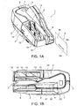
- FIG. 1A is an external oblique view and FIG. 1B is a plan view of a check processing device 1 according to a preferred embodiment of the invention.
- the check processing device 1 has a case 2 on the main unit and a pair of left and right access covers 4 and 5 that open and close pivoting on a vertical support pin 3 disposed at the back end of the case 2.
- a check transportation path 7 for conveying checks 6 is formed between the case 2 and the access covers 4 and 5.
- the check transportation path 7 is a narrow vertical slot that curves in a basically U-shaped configuration when seen from above.
- the upstream end of the check transportation path 7 in the check transportation direction is connected through a check infeed path 8 that is a narrow vertical channel to a check supply unit 9, which is a wide vertical channel.
- the downstream end of the check transportation path 7 is connected to a check storage unit 10.
- the check storage unit 10 has first and second branch paths 11 and 12 connected to the downstream end of the check transportation path 7, and first and second storage pockets 13 and 14 connected to the downstream ends of the first and second branch paths 11 and 12.
- each check 6 has an MICR line 6A printed along the long bottom edge on the front 6a of the check 6. Also recorded on the front 6a against a patterned background are the check amount, payer and payee, various numbers, and the payer signature. An endorsement is recorded on the back 6b of the check 6.
- a front contact image scanner 21 for imaging the fronts of the checks 6 a back contact image scanner 22 for imaging the backs of the checks 6, a magnetic head 23 for reading magnetic ink characters, and a printing mechanism 24 for printing ELECTRONIC FUNDS TRANSFER, for example, on the check front are disposed in this order along the check transportation path 7.
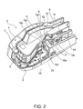
- FIG. 2 is an oblique view of the check processing device with one of the access covers 5 removed.
- the downstream end of the check transportation path 7 is divided into first and second branch paths 11 and 12 by a diversion unit 18. While the transportation path is divided into only two branch paths in this example, there could be three or more branches.
- the diversion unit 18 has right and left diversion unit guide surfaces 18a and 18b, and a diversion unit top 18c connecting the top edges of the diversion unit guide surfaces 18a and 18b.
- the diversion unit guide surfaces 18a and 18b spread apart to the right and left in the downstream branching direction from a vertex at the branching position A between the first and second branch paths 11 and 12.
- the first branch path 11, of which one inside wall is defined by diversion unit guide surface 18a, continues in a straight line from the downstream end of the check transportation path 7.
- the angle is approximately 30 degrees in this embodiment of the invention, but can be any angle less than 90 degrees and is not limited to 30 degrees.
- a switching lever 19 for directing the in-fed check 6 to either one of the first and second branch paths 11 and 12 is disposed at the branching position A.
- the flapper 19 has right and left flapper guide surfaces 19a and 19b that diverge to the right and left in the diversion directions of the first and second branch paths 11 and 12, and a level lever top 19c that covers the top edges of the flapper guide surfaces 19a and 19b.
- the flapper 19 When positioned as seen in FIG. 2 , the flapper 19 closes the upstream end of the second branch path 12 so that a check 6 delivered to the branching position A from the upstream end at the check transportation path 7 is guided by the flapper guide surface 19a and enters the first branch path 11.
- the flapper 19 can also be switched by a switching mechanism 20 disposed below the branching position A to the position closing the upstream end of the first branch path 11.
- a check 6 travelling to the branching position A is guided by the flapper guide surface 19b and enters the second branch path 12.
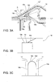
- FIG. 3A is a plan view showing the main parts at the transportation path diversion position.
- FIG. 3B is a section view through line I-I in FIG. 3A
- FIG. 3C is a section view through line II-II in FIG. 3A .
- Line I-I passes through the branching position A and the center between the right and left diversion unit guide surfaces, and line II-II passes through diversion unit top perpendicularly to the direction of each branch path.
- the diversion unit top 18c of the diversion unit 18 slopes upward from the lever top 19c in both left and right diversion directions, and also slopes upward from the top edges of the right and left diversion unit guide surfaces 18a and 18b perpendicularly to the diversion direction.
- the diversion unit top 18c is substantially triangular when seen in plan view, and has an acute angle portion that is defined by the diversion unit guide surfaces 18a and 18b that spread apart to the right and left in the downstream branching direction from a vertex at the branching position A.
- the diversion unit top 18c is finished to a mirror surface.
- the right and left diversion unit guide surfaces 18a and 18b are located to the inside of imaginary lines L1 and L2 extending substantially in the diversion direction of the right and left flapper guide surfaces 19a and 19b of the flapper 19.
- the diversion unit top 18c slopes upward in each of the diversion directions.
- the sectional shape of the diversion unit top 18c perpendicularly to the diversion directions is defined by a convex curved surface that bridges the top edges of the diversion unit guide surfaces 18a and 18b extending in the diversion directions.
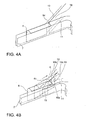
- FIG. 4A shows a diversion unit that does not have a diversion unit top as described above
- FIG. 4B shows a diversion unit with the foregoing diversion unit top.
- the diversion unit 18 has a diversion unit top 18c as described above, the drooping portion 6c at the top of the check 6 is guided by the diversion unit top 18c to ride over the diversion unit 18, thereby avoiding a collision between the check 6 and the diversion unit 18.
- the diversion unit top 18c inclines upward in the directions in which the transportation path diverges (the check transportation direction) as well as perpendicularly to the diversion directions.
- the drooping portion 6c of the in-fed check is thereby gradually raised so that it passes over the diversion unit 18.
- the diversion unit top 18c has a mirror finish, the drooping portion 6c of the check 6 is guided smoothly up so that it rides over the diversion unit 18.
- the check 6 guided by the flapper guide surfaces 19a and 19b also does not collide with the diversion unit guide surfaces 18a and 18b.
- the drooping portion of the check is again guided up by the diversion unit top 18c so that it passes over the diversion unit 18.
- the check 6 is thus also prevented from colliding with the diversion unit 18 and jamming when the check 6 enters the first branch path 11.
- the diversion unit top 18c has a convex curved surface when seen in a section view perpendicular to the branching directions of the first and second branch paths 11 and 12, but the diversion unit top 18c could be a flat inclined surface that slopes upward from the top edges of the guide surfaces 18a and 18b of the diversion unit 18.
- check transportation path 7 splits into two branch paths, but the structure of the diversion unit described above for directing checks to the desired branch path can be also be used when the check transportation path 7 splits into three or more branches.
- the diversion unit top 18c is rendered to the diversion unit 18 as a three-dimensionally inclined surface for guiding the drooping portion 6c of a check 6 in the foregoing embodiments, but the lever top 19c of the flapper 19 can be rendered as a three-dimensionally inclined guide surface.
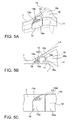
- FIG. 5 shows an example in which the top of the path switching lever (flapper) is rendered as a three-dimensionally inclined guide surface.
- FIG. 5A is an oblique view of the diversion unit area
- FIG. 5B is a plan view of the same
- FIG. 5C is a side view from the side of the flapper and the diversion unit.
- lever top 19c slopes up in the right and left diversion directions while also sloping up from the top edges of the flapper guide surfaces 19a and 19b substantially perpendicularly to the directions in which the branch path diverges. More particularly, the lever top 19c is shaped similarly to the diversion unit top 18c described above.
- top of the flapper is thus rendered as a three-dimensionally inclined guide surface and the right and left guide surfaces 18a and 18b of the diversion unit 18 are positioned set back to the inside from imaginary lines L3 and L4 extending substantially in the diversion direction of the right and left guide surfaces 19a and 19b of the flapper 19, a check 6 guided by the flapper guide surfaces 19a and 19b can be prevented from colliding with the diversion unit guide surfaces 18a and 18b.
- the edge 18d of the diversion unit top 18c facing the flapper 19 is positioned below an imaginary line L5 extending the lever top 19c in the diversion direction, a check 6 guided by the lever top 19c can be prevented from colliding with the diversion unit top 18c.
Landscapes
- Engineering & Computer Science (AREA)
- Mechanical Engineering (AREA)
- Separation, Sorting, Adjustment, Or Bending Of Sheets To Be Conveyed (AREA)
Claims (5)
- Trennmechanismus für eine Blattmedienverarbeitungsvorrichtung, umfassend:einen Blattmedientransportweg (7), bei dem es sich um einen vertikalen Einschub handelt, der ausgelegt ist, ein Blattmedium zu befördern, dessen oberer Teil typischerweise über den oberen Teil des Blattmedientransportwegs (7) vorstehen kann;eine Trenneinheit (18), die ausgelegt ist, den Blattmedientransportweg in einen rechten und einen linken Abzweigungsweg (11, 12) zu teilen; undeinen Abzweigungs-Umschalthebel (19), der ausgelegt ist, Blattmedien, die an eine Abzweigungsweg-Trennposition befördert werden, in einen der Abzweigungswege (11, 12) zu führen, wobeidie Trenneinheit (18) eine linke und eine rechte Trenneinheit-Leitfläche (18a, 18b) hat, die sich in eine linke und eine rechte Trennrichtung ausbreiten, und einen Trenneinheit-Oberteil (18c), der die Oberkanten der Trenneinheit-Leitflächen (18a, 18b) verbindet; undwobei der Abzweigungs-Umschalthebel (19) eine linke und eine rechte Hebelseiten-Leitfläche (19a, 19b) hat, die sich in die linke und die rechte Trennrichtung des Blattmedientransportwegs (7) ausbreiten, und einen Hebel-Oberteil (19c), der die Oberkanten der Hebelseiten-Leitflächen (19a, 19b) verbindet;dadurch gekennzeichnet, dassder Trenneinheit-Oberteil (18c) in die linke und rechte Trennrichtung vom Hebel-Oberteil (19c) nach oben geneigt ist und im rechten Winkel zur linken und rechten Trennrichtung des Blattmedientransportwegs (7) von den Oberkanten der linken und der rechten Trenneinheit-Leitfläche (18a, 18b) nach oben geneigt ist.
- Trennmechanismus nach Anspruch 1, wobei die Form des Trenneinheit-Oberteils (18c) in der Querschnittsansicht im rechten Winkel zur linken und rechten Trennrichtung des Blattmedientransportwegs (7) eine konvexe Kurve ist.
- Trennmechanismus nach Anspruch 1 oder 2, wobei der Trenneinheit-Oberteil (18c) eine verspiegelte Oberfläche hat.
- Trennmechanismus nach einem der vorhergehenden Ansprüche, wobei die linke und die rechte Trenneinheit-Leitfläche (18a, 18b) der Trenneinheit (18) in einem Winkel von weniger als 90 Grad voneinander divergieren.
- Trennmechanismus nach einem der vorhergehenden Ansprüche, wobei die linke und die rechte Trenneinheit-Leitfläche (18a, 18b) von imaginären Linien (L1, L2), die die linke und die rechte Hebelseiten-Leitfläche (19a, 19b) in die linke und die rechte Trennrichtung des Blattmedientransportwegs (7) verlängern, nach innen zurückgesetzt positioniert sind.
Applications Claiming Priority (1)
| Application Number | Priority Date | Filing Date | Title |
|---|---|---|---|
| JP2007186607A JP4905276B2 (ja) | 2007-07-18 | 2007-07-18 | シート状媒体処理装置の分岐部構造およびシート状媒体処理装置 |
Publications (3)
| Publication Number | Publication Date |
|---|---|
| EP2017208A2 EP2017208A2 (de) | 2009-01-21 |
| EP2017208A3 EP2017208A3 (de) | 2009-08-05 |
| EP2017208B1 true EP2017208B1 (de) | 2014-03-12 |
Family
ID=39870026
Family Applications (1)
| Application Number | Title | Priority Date | Filing Date |
|---|---|---|---|
| EP08012907.5A Not-in-force EP2017208B1 (de) | 2007-07-18 | 2008-07-17 | Medientrennmechanismus für eine Blattmedienverarbeitungsvorrichtung |
Country Status (4)
| Country | Link |
|---|---|
| US (1) | US7988151B2 (de) |
| EP (1) | EP2017208B1 (de) |
| JP (1) | JP4905276B2 (de) |
| ES (1) | ES2462742T3 (de) |
Families Citing this family (3)
| Publication number | Priority date | Publication date | Assignee | Title |
|---|---|---|---|---|
| FR2983842B1 (fr) * | 2011-12-13 | 2014-07-04 | Solystic | Dispositif de convoyage pour objets plats sur chant et machine de tri postal |
| CN103632432B (zh) * | 2012-08-24 | 2016-04-20 | 山东新北洋信息技术股份有限公司 | 支票处理设备 |
| CN106373261B (zh) * | 2016-10-17 | 2022-08-30 | 深圳怡化电脑股份有限公司 | 导钞装置 |
Citations (1)
| Publication number | Priority date | Publication date | Assignee | Title |
|---|---|---|---|---|
| US3162437A (en) * | 1961-10-11 | 1964-12-22 | Sperry Rand Corp | Document output mechanism |
Family Cites Families (10)
| Publication number | Priority date | Publication date | Assignee | Title |
|---|---|---|---|---|
| IT1059759B (it) * | 1975-05-30 | 1982-06-21 | Licentia Gmbh | Dispositivo trasportatore ripartitore |
| US4913295A (en) * | 1985-04-08 | 1990-04-03 | Banctec, Inc. | Apparatus for processing remittance and remittance advice documents |
| FR2677003B1 (fr) | 1991-05-30 | 1993-10-01 | Bertin Et Cie | Dispositif pour deplacer une piece mobile entre une premiere et une seconde positions et la maintenir dans chacune de ces positions. |
| JPH0733307A (ja) | 1993-07-16 | 1995-02-03 | Omron Corp | 小切手処理装置 |
| JP4064137B2 (ja) * | 2002-03-28 | 2008-03-19 | グローリー株式会社 | 紙幣処理装置 |
| JP2004206362A (ja) * | 2002-12-25 | 2004-07-22 | Canon Electronics Inc | 小切手類読取装置 |
| US20040144697A1 (en) * | 2003-01-24 | 2004-07-29 | Roland Ramonowski | Diverter gate with wear attachment |
| JP4349259B2 (ja) * | 2003-11-10 | 2009-10-21 | セイコーエプソン株式会社 | 画像読取装置および画像読取装置を備えた複合処理装置 |
| JP4720161B2 (ja) | 2004-12-01 | 2011-07-13 | セイコーエプソン株式会社 | 複合処理装置及びその制御方法 |
| JP4837592B2 (ja) * | 2006-05-29 | 2011-12-14 | 株式会社リコー | 記録媒体搬送装置および画像形成装置 |
-
2007
- 2007-07-18 JP JP2007186607A patent/JP4905276B2/ja not_active Expired - Fee Related
-
2008
- 2008-07-16 US US12/218,513 patent/US7988151B2/en active Active
- 2008-07-17 EP EP08012907.5A patent/EP2017208B1/de not_active Not-in-force
- 2008-07-17 ES ES08012907.5T patent/ES2462742T3/es active Active
Patent Citations (1)
| Publication number | Priority date | Publication date | Assignee | Title |
|---|---|---|---|---|
| US3162437A (en) * | 1961-10-11 | 1964-12-22 | Sperry Rand Corp | Document output mechanism |
Also Published As
| Publication number | Publication date |
|---|---|
| JP4905276B2 (ja) | 2012-03-28 |
| US7988151B2 (en) | 2011-08-02 |
| EP2017208A3 (de) | 2009-08-05 |
| EP2017208A2 (de) | 2009-01-21 |
| US20090184465A1 (en) | 2009-07-23 |
| ES2462742T3 (es) | 2014-05-26 |
| JP2009023759A (ja) | 2009-02-05 |
Similar Documents
| Publication | Publication Date | Title |
|---|---|---|
| EP2017208B1 (de) | Medientrennmechanismus für eine Blattmedienverarbeitungsvorrichtung | |
| CN101329794B (zh) | 记录介质处理装置 | |
| AP1742A (en) | Smart documents. | |
| JP2004297761A (ja) | データ読取装置 | |
| US9519846B2 (en) | Card reader | |
| JP4770757B2 (ja) | 媒体送り出し装置および媒体処理装置 | |
| JP5647798B2 (ja) | 紙葉取扱装置 | |
| CN103426233B (zh) | 介质收集装置以及介质处理装置 | |
| EP3051465B1 (de) | Kartenleser | |
| KR102010314B1 (ko) | 카드 처리 장치, 자동 거래 장치 | |
| JP5033606B2 (ja) | カード搬送機構 | |
| CN106233343A (zh) | 介质处理装置及自动交易装置 | |
| US11797964B2 (en) | Automated transaction machine | |
| JP4323329B2 (ja) | カードリーダ | |
| JP2008165483A (ja) | カード回収機構およびカード発行装置 | |
| JP2008021140A (ja) | 紙葉類取扱装置 | |
| JP2017123128A (ja) | カード処理装置 | |
| US20090039596A1 (en) | Sheet media storage device and sheet media processing device | |
| CN106056791B (zh) | 介质输送装置及介质交易装置 | |
| JP2009029537A (ja) | シート収納装置および媒体処理装置 | |
| JP5397041B2 (ja) | 媒体挿入部 | |
| JP4838156B2 (ja) | 媒体搬送機構 | |
| JPH0729457B2 (ja) | 通帳類自動発行装置 | |
| JP6916147B2 (ja) | 紙葉類読取装置及び紙葉類排出方法 | |
| JP4113803B2 (ja) | カード挿入口機構 |
Legal Events
| Date | Code | Title | Description |
|---|---|---|---|
| PUAI | Public reference made under article 153(3) epc to a published international application that has entered the european phase |
Free format text: ORIGINAL CODE: 0009012 |
|
| AK | Designated contracting states |
Kind code of ref document: A2 Designated state(s): AT BE BG CH CY CZ DE DK EE ES FI FR GB GR HR HU IE IS IT LI LT LU LV MC MT NL NO PL PT RO SE SI SK TR |
|
| AX | Request for extension of the european patent |
Extension state: AL BA MK RS |
|
| PUAL | Search report despatched |
Free format text: ORIGINAL CODE: 0009013 |
|
| AK | Designated contracting states |
Kind code of ref document: A3 Designated state(s): AT BE BG CH CY CZ DE DK EE ES FI FR GB GR HR HU IE IS IT LI LT LU LV MC MT NL NO PL PT RO SE SI SK TR |
|
| AX | Request for extension of the european patent |
Extension state: AL BA MK RS |
|
| 17P | Request for examination filed |
Effective date: 20091201 |
|
| AKX | Designation fees paid |
Designated state(s): DE ES FR GB IT |
|
| 17Q | First examination report despatched |
Effective date: 20110323 |
|
| GRAP | Despatch of communication of intention to grant a patent |
Free format text: ORIGINAL CODE: EPIDOSNIGR1 |
|
| INTG | Intention to grant announced |
Effective date: 20131126 |
|
| GRAS | Grant fee paid |
Free format text: ORIGINAL CODE: EPIDOSNIGR3 |
|
| GRAA | (expected) grant |
Free format text: ORIGINAL CODE: 0009210 |
|
| AK | Designated contracting states |
Kind code of ref document: B1 Designated state(s): DE ES FR GB IT |
|
| REG | Reference to a national code |
Ref country code: GB Ref legal event code: FG4D |
|
| REG | Reference to a national code |
Ref country code: DE Ref legal event code: R096 Ref document number: 602008030727 Country of ref document: DE Effective date: 20140424 |
|
| REG | Reference to a national code |
Ref country code: ES Ref legal event code: FG2A Ref document number: 2462742 Country of ref document: ES Kind code of ref document: T3 Effective date: 20140526 |
|
| REG | Reference to a national code |
Ref country code: DE Ref legal event code: R097 Ref document number: 602008030727 Country of ref document: DE |
|
| PLBE | No opposition filed within time limit |
Free format text: ORIGINAL CODE: 0009261 |
|
| STAA | Information on the status of an ep patent application or granted ep patent |
Free format text: STATUS: NO OPPOSITION FILED WITHIN TIME LIMIT |
|
| 26N | No opposition filed |
Effective date: 20141215 |
|
| REG | Reference to a national code |
Ref country code: DE Ref legal event code: R097 Ref document number: 602008030727 Country of ref document: DE Effective date: 20141215 |
|
| REG | Reference to a national code |
Ref country code: FR Ref legal event code: PLFP Year of fee payment: 9 |
|
| REG | Reference to a national code |
Ref country code: FR Ref legal event code: PLFP Year of fee payment: 10 |
|
| REG | Reference to a national code |
Ref country code: FR Ref legal event code: PLFP Year of fee payment: 11 |
|
| PGFP | Annual fee paid to national office [announced via postgrant information from national office to epo] |
Ref country code: IT Payment date: 20220613 Year of fee payment: 15 Ref country code: GB Payment date: 20220606 Year of fee payment: 15 |
|
| PGFP | Annual fee paid to national office [announced via postgrant information from national office to epo] |
Ref country code: FR Payment date: 20220609 Year of fee payment: 15 |
|
| PGFP | Annual fee paid to national office [announced via postgrant information from national office to epo] |
Ref country code: ES Payment date: 20220801 Year of fee payment: 15 Ref country code: DE Payment date: 20220531 Year of fee payment: 15 |
|
| REG | Reference to a national code |
Ref country code: DE Ref legal event code: R119 Ref document number: 602008030727 Country of ref document: DE |
|
| GBPC | Gb: european patent ceased through non-payment of renewal fee |
Effective date: 20230717 |
|
| PG25 | Lapsed in a contracting state [announced via postgrant information from national office to epo] |
Ref country code: DE Free format text: LAPSE BECAUSE OF NON-PAYMENT OF DUE FEES Effective date: 20240201 Ref country code: GB Free format text: LAPSE BECAUSE OF NON-PAYMENT OF DUE FEES Effective date: 20230717 |
|
| PG25 | Lapsed in a contracting state [announced via postgrant information from national office to epo] |
Ref country code: FR Free format text: LAPSE BECAUSE OF NON-PAYMENT OF DUE FEES Effective date: 20230731 |
|
| PG25 | Lapsed in a contracting state [announced via postgrant information from national office to epo] |
Ref country code: IT Free format text: LAPSE BECAUSE OF NON-PAYMENT OF DUE FEES Effective date: 20230717 |
|
| REG | Reference to a national code |
Ref country code: ES Ref legal event code: FD2A Effective date: 20240830 |
|
| PG25 | Lapsed in a contracting state [announced via postgrant information from national office to epo] |
Ref country code: ES Free format text: LAPSE BECAUSE OF NON-PAYMENT OF DUE FEES Effective date: 20230718 |
|
| PG25 | Lapsed in a contracting state [announced via postgrant information from national office to epo] |
Ref country code: ES Free format text: LAPSE BECAUSE OF NON-PAYMENT OF DUE FEES Effective date: 20230718 |