EP2015138A1 - Anzeigevorrichtung - Google Patents
Anzeigevorrichtung Download PDFInfo
- Publication number
- EP2015138A1 EP2015138A1 EP08252101A EP08252101A EP2015138A1 EP 2015138 A1 EP2015138 A1 EP 2015138A1 EP 08252101 A EP08252101 A EP 08252101A EP 08252101 A EP08252101 A EP 08252101A EP 2015138 A1 EP2015138 A1 EP 2015138A1
- Authority
- EP
- European Patent Office
- Prior art keywords
- section
- image
- screen
- display device
- reflection
- Prior art date
- Legal status (The legal status is an assumption and is not a legal conclusion. Google has not performed a legal analysis and makes no representation as to the accuracy of the status listed.)
- Withdrawn
Links
- 238000003702 image correction Methods 0.000 claims description 21
- 230000008859 change Effects 0.000 description 13
- 238000010586 diagram Methods 0.000 description 13
- 230000004044 response Effects 0.000 description 6
- 230000000694 effects Effects 0.000 description 4
- 239000004973 liquid crystal related substance Substances 0.000 description 3
- 239000003550 marker Substances 0.000 description 3
- 230000003287 optical effect Effects 0.000 description 3
- 230000004907 flux Effects 0.000 description 2
- QSHDDOUJBYECFT-UHFFFAOYSA-N mercury Chemical compound [Hg] QSHDDOUJBYECFT-UHFFFAOYSA-N 0.000 description 2
- 229910052753 mercury Inorganic materials 0.000 description 2
- 230000009467 reduction Effects 0.000 description 2
- 238000005549 size reduction Methods 0.000 description 2
- 230000003213 activating effect Effects 0.000 description 1
- 230000008901 benefit Effects 0.000 description 1
- 230000005540 biological transmission Effects 0.000 description 1
- 230000000903 blocking effect Effects 0.000 description 1
- 230000015556 catabolic process Effects 0.000 description 1
- 230000003247 decreasing effect Effects 0.000 description 1
- 238000006731 degradation reaction Methods 0.000 description 1
- 239000011159 matrix material Substances 0.000 description 1
- 238000000034 method Methods 0.000 description 1
- 230000008569 process Effects 0.000 description 1
- 230000000717 retained effect Effects 0.000 description 1
- 239000007787 solid Substances 0.000 description 1
Images




Classifications
-
- G—PHYSICS
- G03—PHOTOGRAPHY; CINEMATOGRAPHY; ANALOGOUS TECHNIQUES USING WAVES OTHER THAN OPTICAL WAVES; ELECTROGRAPHY; HOLOGRAPHY
- G03B—APPARATUS OR ARRANGEMENTS FOR TAKING PHOTOGRAPHS OR FOR PROJECTING OR VIEWING THEM; APPARATUS OR ARRANGEMENTS EMPLOYING ANALOGOUS TECHNIQUES USING WAVES OTHER THAN OPTICAL WAVES; ACCESSORIES THEREFOR
- G03B21/00—Projectors or projection-type viewers; Accessories therefor
- G03B21/14—Details
- G03B21/28—Reflectors in projection beam
-
- G—PHYSICS
- G03—PHOTOGRAPHY; CINEMATOGRAPHY; ANALOGOUS TECHNIQUES USING WAVES OTHER THAN OPTICAL WAVES; ELECTROGRAPHY; HOLOGRAPHY
- G03B—APPARATUS OR ARRANGEMENTS FOR TAKING PHOTOGRAPHS OR FOR PROJECTING OR VIEWING THEM; APPARATUS OR ARRANGEMENTS EMPLOYING ANALOGOUS TECHNIQUES USING WAVES OTHER THAN OPTICAL WAVES; ACCESSORIES THEREFOR
- G03B21/00—Projectors or projection-type viewers; Accessories therefor
- G03B21/14—Details
- G03B21/53—Means for automatic focusing, e.g. to compensate thermal effects
Definitions
- the present invention relates to a display device that performs image display by projecting image lights onto a screen.
- projectors are used for projecting image lights onto a screen.
- Using such a projector requires a space large enough for placement of both the screen and the projector.
- the screen is placed to be substantially vertical, and the projector is placed at a place away from the screen.
- the projector gets in their sights, thereby preventing viewing of entire images projected on the screen.
- an all-in-one reflective projector system which can be placed in a small space, proposed to configure a projector and a screen in a piece for the purpose of not blocking image viewing by the presenter or the projector itself
- Patent Document 1 Japanese Patent No. 3864051
- an arm movable arm
- the screen reflective projection screen
- the arm is provided thereon with a projection section (reflective projection head) for enlarging projection of image lights.
- the image lights are directed to the screen located diagonally below the projection section for image display.
- An advantage of some aspects of the invention is to solve at least a part of the problems mentioned above.
- a first aspect of the invention is to provide a display device includes a screen unit that is provided with a projection section that enlarges and projects an image light, and a screen.
- An arm section is attached to the screen unit to be protruded therefrom.
- a reflection unit is attached to the arm section, and is provided with a reflection mirror that reflects the image light projected by the projection section toward the screen.
- the projection section is provided to the screen unit so that, for placement of the screen unit, the arm section is reduced in weight compared with the case where the arm section includes the projection section.
- the lighter arm section as such, the weight balance is not lost as easily, and may provide display device with satisfactory stability.
- the reflection unit is configured to be changeable in a direction of reflecting the image light.
- the reflection unit can be changed in a direction of reflecting image lights, thereby allowing image display at various positions on the screen.
- image projection may be allowed not only onto the screen but also onto room walls and desks, for example.
- an image correction section is provided for correcting distortion of an image displayed on the screen.
- this display device is provided with the image correction section that corrects any distortion of images, thereby being able to display distortion-suppressed images with whatever reflection direction.
- the image correction section corrects the distortion of the image in conjunction with a change of the direction of reflection made in the reflection unit.
- the image correction section corrects any distortion of images in conjunction with any change made for the reflection direction of the reflection unit. Accordingly, users can view distortion-free images with no need for operation for distortion correction.
- the arm section is configured to adjustably extend or contract to allow a change of protrusion degree with respect to the screen.
- the arm section is so configured as to be adjustably extended or contracted so that the distance between the screen and the reflection unit can be changed. This accordingly enables to change the distance of an optical path from the projection section to the screen, i.e., projection distance, so that the images can be changed in size.
- the reflection mirror has a reflection surface of convex shape.
- the reflection mirror has a reflection surface of convex shape
- images can be increased in size to a further degree compared with a case with any reflection mirror having a flat reflection surface. Accordingly, if with images of a size, the projection distance can be reduced, and thus the arm section can be reduced in length so that the protrusion degree of the arm section can be suppressed with respect to the screen. If the projection distance remains the same with images of a size, the magnification of the projection section can be lowered, thereby achieving the simplification of the lens configuration and the reduction of the lens size.
- the screen is a white board that allows pen-based writing and erasing of the writing.
- the screen is a white board that allows pen-based writing and erasing of the writing, in addition to image display thereon by image projection, any details of conferences and meetings can be written thereon.
- the screen unit is provided with a reading section that reads a written image written on the screen, and an output section that outputs the image read by the reading section.
- the screen unit is provided with the reading section that reads a written image written on the screen, and the output section that outputs the image read by the reading section. Accordingly, any written images can be stored with no need for copying thereof.
- the arm section is attached with an image-capture section that can capture an image of the screen
- the screen unit is provided with an output section that outputs the image captured by the image-capture section.
- the arm section is attached with the image-capture section that can capture an image of the screen
- the screen unit is provided with an output section that outputs the image captured by the image-capture section.
- the output section is provided with a printing section that prints the captured image on paper.
- the output section is provided with the printing section. This accordingly enables to store any images written on the screen after printing.
- the output section is provided with an interface section that can be connected to an external device.
- the output section is provided with the interface section. This accordingly enables to transfer any images written on the screen to an external device such as PC (Personal Computer). As such, the application purposes can be extended for image storage and image display to a large number of people, for example.
- PC Personal Computer
- FIG. 1 is a perspective view of a display device of a first embodiment, viewed from the upper front surface thereof.
- FIG. 2 is a block diagram for illustrating the schematic configuration of the display device of the first embodiment.
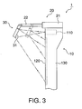
- FIG. 3 is a side view of the display device of the first embodiment.
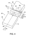
- FIG. 4 is a perspective view of a tip end portion of a movable section and a reflection unit, viewed from above thereof.
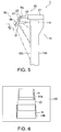
- FIG. 5 is a side view of the display device of the first embodiment.
- FIG. 6 is a front view of a screen.
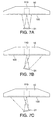
- FIGS. 7A to 7C are each a plan view of the display device, viewed from the top side thereof.
- FIG. 8 is a front view of the screen of FIGS. 7A to 7C .
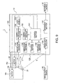
- FIG. 9 is a block diagram for illustrating the schematic configuration of a display device of a second embodiment.
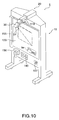
- FIG. 10 is an outer view of the display device of the second embodiment.
- FIG. 11 is a block diagram for illustrating the schematic configuration of a display device of a third embodiment.
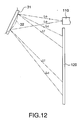
- FIG. 12 is a schematic diagram for comparison in terms of an optical path for reflection of image lights between a reflection mirror having a flat reflection surface and another reflection mirror having a concave reflection surface.
- the display device of this embodiment is of a type that displays images by projecting image lights from a projection section onto a screen.
- FIG. 1 is a diagram showing the outer appearance of the display device of this embodiment, i.e., a perspective view of the display device viewed from the upper front surface side.
- a display device 1 is configured to include a screen unit 10, an arm section 20, and a reflection unit 30.
- the screen unit 10 is configured to include a screen 120 and a projection section 110.
- the screen 120 is retained by a chassis 130, and is in the shape of square when it is viewed from the front surface side.
- the projection section 110 is housed in the chassis 130 at its substantially upper center portion.
- the arm section 20 is so attached as to be protruded from the screen unit 10, and at the tip end of the arm section 20, the reflection unit 30 provided with a reflection mirror 31 is attached.
- the projection section 110 projects image lights from an aperture portion formed to the front surface of the chassis 130 toward the reflection unit 30.
- the reflection unit 30 reflects the image lights toward the screen 120 for image display on the screen 120.
- the reflection unit 30 can be changed in reflection direction for image lights, and with such a change of reflection direction, images to be displayed on the screen 120 can be changed in position in the vertical and lateral directions.
- the chassis 130 is formed at its lower portion with two leg sections 131, and below these leg sections 131, rollers 132 are attached so that the display device 1 can be freely moved for placement.
- FIG. 2 is a block diagram for illustrating the schematic configuration of the display device 1.
- the screen unit 10 is configured to include an operation section 140, an image input section 150, a control section 151, an image correction section 152, a light source 153, a light modulation section 154, the projection section 110, the screen 120, and the chassis 130.
- the operation section 140 is provided with a plurality of keys for making various settings to the display device 1.
- the keys include a power key for turning on/off the power, up and down keys for an operation of changing the image position in the vertical direction, right and left keys for an operation of changing the image position in the lateral direction, and others.
- the image input section 150 is configured to include a connection terminal, which is provided for a connection, via a cable, with an external image output device 50 such as PC (Personal Computer) and DVD (Digital Versatile Disc) reproduction device.
- the image input section 150 forwards an image signal coming from the image output device 50 to the control section 151.
- the control section 151 generates a display image signal by processing the image signal provided by the image input section 150, and forwards the resulting signal to the image correction section 152.
- the control section 151 performs control to change the reflection direction for the image lights.
- the image correction section 152 performs correction of image distortion caused by any position change made to the images.
- the display image signal after such a correction is forwarded to the light modulation section 154.
- the light source 153 is configured by an ultra-high-pressure mercury lamp, for example, and emits luminous fluxes.
- the light modulation section 154 is configured by a liquid crystal panel, for example, and has a rectangular-shaped pixel area in which tiny pixels are arranged in a matrix.
- the light modulation section 154 sets each of the pixels to a light transmission ratio based on the display image signal provided by the image correction section 152 so that a modulated image is formed in the pixel area. Thereafter, the light modulation section 154 modulates, in the pixel area, the luminous fluxes coming from the light source 153 so that image lights are formed.
- the projection section 110 is configured to include a plurality of lenses, and enlarges and projects the image lights formed by the light modulation section 154.
- the arm section 20 is configured so as to be able to adjustably extend and contract, and carries therein a motor My.
- a command comes from the control section 151 so that the motor My responsively drives the reflection unit 30 to change the reflection direction for the image lights in such a manner that the image position is changed in the vertical direction.
- the reflection unit 30 is configured to include the reflection mirror 31 and a motor Mx .
- the reflection mirror 31 reflects an image light ( Lo ) coming from the projection section 110 toward the screen 120 (reflected light Li) so that an image is displayed on the screen 120.
- a command comes from the control section 151 so that the motor Mx responsively drives the reflection mirror 31 to change the reflection direction for the image lights in such a manner that the image position is changed in the lateral direction.
- FIG. 3 is a side view of the display device 1.
- the arm section 20 is configured to include a fixed section 21 and a movable section 22.
- the fixed section 21 is fixed to the upper end of the chassis 130, and the movable section 22 is inserted into the fixed section 21 to be able to move to slide in the substantially perpendicular direction with respect to the screen 120.
- the arm section 20 can be adjustably extended or contracted.
- the tip end of the movable section 22 is attached with the reflection unit 30, and when the arm section 20 is adjustably extended or contracted, the projection distance can be changed.
- the projection distance is increased so that the image is increased in size.
- the projection distance is decreased so that the image is reduced in size.
- the images can be increased or reduced in size.
- the projection distance is reduced for such a purpose, and there thus is no need for decimating any modulated images of the light modulation section 154 for size reduction of images. This makes it possible to achieve image display with little or no degradation of image quality.
- the degree of protuberance of the arm section 20 can be reduced so that the storage space can be favorably reduced.
- FIG. 4 is a perspective view of the tip end portion of the movable section 22 and the reflection unit 30 viewed from above, and FIG. 5 is a side view of the display device.1.
- the tip end portion of the movable section 22 is formed with a shaft 23 that is substantially horizontal, and whose center axis 24 is substantially parallel to the screen 120.
- the motor My is attached so that its rotation center axis becomes substantially parallel to the center axis 24.
- a gear 25 is placed to transfer the power of the motor My.
- the reflection unit 30 is configured to include a support section 37 and a rotation section 38.
- the support section 37 is provided with the motor Mx, and the rotation section 38 is provided with the reflection mirror 31.
- the support section 37 is configured to include a square-bracket-shaped section 37A and a cylindrical-shaped section 37B.
- a hole 34 is formed to both walls thereof, and on the inner side of the section 37A, a toothed section 35 is formed with a plurality of teeth.
- the section 37B is so formed that its center axis 39 (center axis of the cylindrical shape) becomes substantially perpendicular to the center axis of the hole 34.
- the reflection unit 30 is attached to the movable section 22 by the holes 34 of the support section 37 being engaged with the shaft 23 and by the toothed section 35 being meshed with the gear 25.
- the reflection unit 30 rotates, with respect to the movable section 22, in the directions of ⁇ Ry about the center axis 24.
- the control section 151 drives the motor My based on the key operation so that the reflection unit 30 is rotated in the direction of + Ry (indicated by solid lines in FIG. 5 ). As a result, the reflection unit 30 changes the reflection direction, and changes the image position toward the top.
- the control section 151 drives the motor My based on the key operation so that the reflection unit 30 is rotated in the direction of -Ry (indicated by chain double-dashed lines in FIG. 5 ). As a result, the reflection unit 30 changes the reflection direction, and changes the image position toward the bottom.
- control section 151 drives the motor My based on the operation of the up and down keys to rotate the reflection unit 30 in the directions of ⁇ Ry .
- the reflection unit 30 then changes the reflection direction for image lights for image display on the screen 120 at various positions in the vertical direction.
- Such an image position change by changing the reflection direction causes trapezoidal distortion with which images are trapezoidally distorted.
- the projection section 110 is so set that images are displayed in square with no such trapezoidal distortion when the images are displayed by the reflection unit 30 substantially at the center portion of the screen 120, i.e., in the reference state.
- the image correction section 152 accordingly performs a correction.
- FIG. 6 is a front view of the screen 120.
- the control section 151 drives the motor My to rotate the reflection unit 30 in the direction of +Ry.
- the control section 151 also issues a command to the image correction section 152 to make it correct a display image signal in such a manner that a modulated image to be formed by the light modulation section 154 will be in the shape that can cancel out any trapezoidal distortion of an image IHa in a case of no correction.
- the screen 120 displays thereon a square-shaped image la.
- square-shaped includes rectangular-shaped.
- the control section 151 drives the motor My to rotate the reflection unit 30 in the direction of -Ry.
- the control section 151 also issues a command to the image correction section 152 to make it correct a display image signal in such a manner that a modulated image to be formed by the light modulation section 154 will be in the shape that can cancel out any trapezoidal distortion of an image IHb in a case of no correction.
- the screen 120 displays thereon a square-shaped image Ib.
- the image correction section 152 corrects any image distortion. Accordingly, users can view distortion-free images with no need for operation for distortion correction.
- the reflection unit 30 is so configured that image position can be changed in the lateral direction of the screen 120.
- the motor Mx is so attached to the support section 37 that its rotation center axis becomes substantially parallel to the center axis 39 of the section 37B.
- the rotation section 38 of the reflection unit 30 is formed with a toothed section that is not shown but is with a plurality of teeth.
- the rotation section 38 is attached to the support section 37 by the toothed section being meshed with a pinion provided to the motor Mx.
- the rotation section 38 is rotated, with respect to the support section 37, in the directions of ⁇ Rx about the center axis 39.
- the center axis 39 is so formed as to be substantially perpendicular to the center axis of the hole 34, and because the hole 34 is being engaged with the axis 23, the center axis 39 and the center axis 24 are configured to be substantially perpendicular to each other.
- FIGS. 7A to 7C are each a plan view of the display device 1 viewed from the top side, showing the screen unit 10 and the reflection mirror 31 of the reflection unit 30.
- FIG. 7A is a diagram showing the state that image lights are being reflected when the reflection unit 30 is in the reference state
- FIG. 7B is a diagram showing the state in which the image lights are being reflected toward the right side of the screen 120
- FIG. 7C is a diagram showing the state in which the image lights are being reflected toward the left side of the screen 120.
- the reflection mirror 31 when the reflection unit 30 is in the reference state, the reflection mirror 31 reflects image lights toward the substantially center portion of the screen 120, thereby displaying images at the substantially center portion of the screen 120.
- the control section 151 drives the motor Mx based on the key operation so that the rotation section 38 is rotated in the direction of +Rx (refer to FIG. 4 ).
- the reflection mirror 31 reflects the image lights toward the right side of the screen 120.
- the control section 151 drives the motor Mx based on the key operation so that the rotation section 38 is rotated in the direction of -Rx (refer to FIG. 4 ).
- the reflection mirror 31 reflects the image lights toward the left side of the screen 120.
- control section 151 drives the motor Mx based on the operation of the right and left keys for rotating the rotation section 38 in the directions of ⁇ Rx .
- the reflection mirror 31 then changes the reflection direction for the image lights for displaying images on the screen 120 at various positions in the lateral direction.
- the image correction section 152 performs an image correction not only in conjunction with the operation of the up and down keys but also in conjunction with the operation of the right and left keys.
- FIG. 8 is a front view of the screen 120 of FIGS. 7A to 7C .
- the control section 151 drives the motor Mx to rotate the rotation section 38 in the direction of +Rx (refer to FIG. 4 ).
- the control section 151 also issues a command to the image correction section 152 to make it correct a display image signal in such a manner that a modulated image to be formed by the light modulation section 154 will be in the shape that can cancel out any trapezoidal distortion of an image IHc in a case of no correction.
- the screen 120 displays thereon a square-shaped image Ic.
- the control section 151 drives the motor Mx to rotate the rotation section 38 in the direction of -Rx (refer to FIG. 4 ).
- the control section 151 also issues a command to the image correction section 152 to make it correct a display image signal in such a manner that a modulated image to be formed by the light modulation section 154 will be in the shape that can cancel out any trapezoidal distortion of an image IHd in a case of no correction.
- the screen 120 displays thereon a square-shaped image Id.
- the image correction section 152 corrects any image distortion. Accordingly, users can view distortion-free square-shaped images with no need for operation for distortion correction.
- the screen unit 10 is provided with the projection section 110 that may be heavy in weight due to a plurality of lenses for the purpose of enlarging projection.
- the arm section 20 can be reduced in weight compared with a configuration where the arm section 20 is provided with the projection section 110 such that the resulting display device may have good stability, and the weight balance may be hardly lost.
- the reflection mirror 31 is disposed between the projection section 110 and the screen 120, thereby being able to lengthen the projection distance with relative ease.
- the lens of the projection section 110 may be smaller in size.
- the arm section 20 can be adjustably extended and contracted so that the distance between the screen 120 and the reflection unit 30 may be changed. Accordingly, this enables the changing of the projection distance, and the image size can be accordingly changed.
- the reflection unit 30 may be changed to alter the reflection direction of reflecting image lights, thereby allowing image display at various positions on the screen 120.
- the image correction section 152 may be provided for correcting any distortion of images, thereby assisting in displaying distortion-suppressed images no matter the reflection direction of the reflection unit 30. 6.
- the reflection unit 30 may be changed to alter the reflection direction in response to a key operation made at the operation section 140, and the image correction section 152 may correct the distortion of images in conjunction with the key operation, i.e., any change made in the reflection direction. Accordingly, users may view distortion-free images with little or no need for operation for distortion correction.
- FIG. 9 is a block diagram for illustrating the schematic configuration of the display device 1 of this embodiment, and FIG. 10 is a diagram showing the outer appearance thereof.
- the display device 1 of the embodiment is configured to include, in the screen unit 10 of the first embodiment, a reading section 155, a printing section 156, and an interface section 157.
- the screen 120 is configured by a white board.
- the operation section 140 is configured to include a reading key (not shown) for operating the reading section 155, and a printing key (not shown) for operating the printing section 156.
- the screen 120 is available not only for display of images being projection results from the projection section 110 but also for pen-based writing and erasing of characters, graphics, and others using a marker pen and an eraser, for example.
- the reading section 155 is disposed on the front surface side of the screen 120, and when the reading key or the printing key of the operation section 140 is operated, a command comes from the control section 151. In response to the command, the reading section 155 reads a written image Iw written on the screen 120 while moving in the direction from left to right. Alternatively, the read image Iw may be combined with projection image data from the control section or correction section. The thus read image is forwarded to the control section 151 as an image signal.
- control section 151 stores the image signal provided by the reading section 155, and when the printing key is operated, processes the image signal provided by the reading section 155 for output to the printing section 156.
- the printing section 156 is disposed on the lower left side of the screen 120, and serves as an output section that outputs images read by the reading section 155.
- the printing section 156 responsively prints, for output, images based on the image signal being the processing result by the control section 151.
- the interface section 157 is configured to include a connection terminal for establishing a connection with an external device 51 such as a PC (Personal Computer) via a cable. Needless to say, in this and other embodiments the connection may be wireless.
- the interface section 157 is disposed on the lower right side of the screen 120, and also serves as an output section for outputting images read by the reading section 155. When the interface section 157 is connected with the external device 51, the image signal stored in the control section 151 becomes available for reading from the external device 51.
- the screen 120 may be a white board that is available for writing and erasing of characters, graphics, and others using a marker pen and an eraser, for example. It means that the screen 120 may be available not only for display of projection images but also for writing of details of conferences and meetings.
- the screen unit 10 may be provided with the reading section 155 configured for reading a written image Iw written by a marker pen or others on the screen 120, and the printing section 156 configured to output the image read by the reading section 155.
- the written image Iw may be printed and stored with no need for copying thereof.
- the screen unit 10 may be provided with the interface section 157, and configured to transfer the written image Iw to the external device 51 such as a PC (Personal Computer).
- the application purposes may be extended for storage of the written image Iw and image display to a large number of people, for example.
- FIG. 11 is a block diagram for illustrating the schematic configuration of the display device 1 of this embodiment.
- the display device 1 of this embodiment is configured to include, as an alternative to the reading section 155 in the screen unit 10 of the second embodiment, an image-capture section 158 in the arm section 20.
- the operation section 140 is provided with, as an alternative to the reading key, an image-capture key (not shown) for operating the image-capture section 158.
- a command comes from the control section 151, and the image-capture section 158 responsively captures an image of the screen 120 in its entirety.
- the resulting image is forwarded to the control section 151 as an image signal.
- control section 151 stores the image signal provided by the image-capture section 158, and when the printing key is operated, the image signal provided by the image-capture section 158 is processed for output to the printing section 156.
- the arm section 20 is provided with the image-capture section 158 that may capture an image of the screen 120 in its entirety. As such, a written image and a display image may be captured all at once.
- the arm section 20 is configured so as to be manually extended and contracted.
- the fixed section 21 may be provided with driving means, e.g., motor, for moving the movable section 22 to slide, and the movable section 22 may be moved to slide by activating the driving means based on any key operation.
- the arm section 20 is configured so as to be adjustably extended and contracted in response to when the movable section 22 is moved to slide by being inserted into the fixed section 21.
- a plurality of movable sections and a fixed section may be configured like a rod antenna, and the arm section 20 may be adjustably extended and contracted by moving the movable sections to slide. If this is the configuration, the degree of protuberance of the arm section 20 may be further reduced for housing of the display device 1.
- the fixed section 21 of the arm section 20 is fixed to the upper end of the chassis 130.
- the fixed section 21 may be configured so as to be able to move with respect to the chassis 130, e.g., the fixed section 21 may be configured so as to be able to rotate to be substantially parallel to the screen 120.
- the degree of protuberance of the arm section 20 can be reduced to almost zero by making the arm section 20 to be substantially parallel to the screen 120 through rotation thereof, thereby reducing the storage space to a further degree.
- the arm section 20 may be attached to the upper portion of the chassis 130, and is allowed to adjustably extend and contract when the movable section 22 is moved to slide.
- the arm section 20 may be configured so as to be able to extend and contract like a pantograph, or may be extended from one side surface or the bottom of the chassis 130.
- the projection section may be provided at a side area or a bottom area of the chassis 130/screen unit 10. The configuration of the arm section 20 is not restricted as long as it allows placement of the reflection unit 30 in such a manner that image lights from the projection section 110 are projected on the screen 120.
- images may be changed in size by extending or contracting the arm section 20.
- the projection section 110 may be provided with a lens component for increasing and reducing the image size and a zoom operation section, and through operation of the zoom operation section, the images may be increased or reduced in size.
- images may be changed in size by extending or contracting the arm section 20.
- modulated images of the light modulation section 154 may be additionally processed for increasing and reducing the image size. This may enable an increase or reduce the size of the images to a further degree.
- the reflection unit 30 is configured so as to be able to reflect image lights onto the screen 120.
- the reflection unit 30 may be so configured as to be able to reflect image lights toward the outside of the screen 120. This configuration may allow image projection not only onto the screen but also onto room walls and desks, for example.
- the reflection unit 30 is changed in reflection direction when it is driven by the motors Mx and My. This is surely not restrictive, and the reflection direction may be changed manually.
- the reflection mirror 31 of the above embodiments may have a reflection surface of convex shape.
- FIG. 12 is a schematic diagram for comparison in terms of an optical path for reflection of image lights between the reflection mirror 31 having a flat reflection surface and a reflection mirror 32 having a concave reflection surface.
- an image light (Lc) reflected by the reflection mirror 32 has a wide range of reflection compared with an image light ( Lf ) reflected by the reflection mirror 31. Accordingly, an image as a result of reflection by the reflection mirror 32 whose reflection surface is of convex shape will be larger in size compared with an image as a result of reflection by the reflection mirror 31 whose reflection surface is flat. Accordingly, if images are of a size, using the reflection mirror 32 whose reflection surface is of convex shape can shorten the projection distance. This facilitates the reduction of the length of the arm section 20 so that the degree of protrusion of the arm section 20 can be reduced with respect to the screen 120. Moreover, when images are of a size, if the projection distance remains the same, the magnification of the projection section 110 can be reduced, and may simplify the lens configuration and reduce the lens size in the projection section 110.
- the reflection surface of the reflection mirror 31 of the above embodiments may be aspheric with which image lights are reflected with a higher magnification than those with a flat surface, and the resulting images suffer from less distortion.
- the chassis 130 is formed with the leg sections 131 at its lower portion, and below these leg sections 131, the rollers 132 are attached so that the display device 1 can be freely moved for placement.
- the screen unit 10 may be fixed to the room walls or others.
- the reading section 155 is disposed on the front surface side of the screen 120, and reads the written image Iw written on the screen 120 while moving in the direction from left to right.
- the reading section 155 may be fixed and disposed on the rear surface side of the screen 120, the screen 120 may be rolled from the front surface to the rear surface, and the reading section 155 may read the written image lw while the screen 120 is being moved.
- the screen 120 may be configured by a white board whose both surfaces are available for writing, and this screen 120 may be attached to the chassis 130 to be able to be flipped over for use.
- the light modulation section 154 is a liquid crystal panel. This is surely not restrictive, and the light modulation section 154 may be configured by using a reflective liquid crystal panel or a device with a micromirror, for example.
- the light source 153 is exemplified by the ultra-high-pressure mercury lamp.
- the light source 153 may be a fixed light source such as any other discharge lamp and an LED (Light-Emitting Diode).
Landscapes
- Physics & Mathematics (AREA)
- General Physics & Mathematics (AREA)
- Projection Apparatus (AREA)
- Transforming Electric Information Into Light Information (AREA)
Applications Claiming Priority (1)
| Application Number | Priority Date | Filing Date | Title |
|---|---|---|---|
| JP2007161004A JP2009002982A (ja) | 2007-06-19 | 2007-06-19 | 表示装置 |
Publications (1)
| Publication Number | Publication Date |
|---|---|
| EP2015138A1 true EP2015138A1 (de) | 2009-01-14 |
Family
ID=39705265
Family Applications (1)
| Application Number | Title | Priority Date | Filing Date |
|---|---|---|---|
| EP08252101A Withdrawn EP2015138A1 (de) | 2007-06-19 | 2008-06-18 | Anzeigevorrichtung |
Country Status (4)
| Country | Link |
|---|---|
| US (1) | US20080316438A1 (de) |
| EP (1) | EP2015138A1 (de) |
| JP (1) | JP2009002982A (de) |
| CN (1) | CN101329501A (de) |
Families Citing this family (27)
| Publication number | Priority date | Publication date | Assignee | Title |
|---|---|---|---|---|
| JP2009192559A (ja) * | 2008-02-12 | 2009-08-27 | Brother Ind Ltd | 画像表示装置 |
| JP2009229563A (ja) * | 2008-03-19 | 2009-10-08 | Seiko Epson Corp | プロジェクタ、および反射装置 |
| TWI465826B (zh) * | 2008-09-09 | 2014-12-21 | Coretronic Corp | 微型投影機 |
| JP2010186040A (ja) * | 2009-02-12 | 2010-08-26 | Seiko Epson Corp | プロジェクター |
| JP2010224015A (ja) * | 2009-03-19 | 2010-10-07 | Sanyo Electric Co Ltd | 投写型映像表示装置及び記載ボード及び投写映像システム |
| JP2011107611A (ja) * | 2009-11-20 | 2011-06-02 | Sanyo Electric Co Ltd | 電子機器用スタンド及び映像表示システム |
| GB2483097B (en) * | 2010-08-26 | 2013-12-11 | Promethean Ltd | Safety device for interactive display system |
| CN102566250B (zh) * | 2010-12-22 | 2015-08-19 | 康佳集团股份有限公司 | 一种裸眼自由立体显示的投影系统及显示器 |
| JP2012173911A (ja) * | 2011-02-21 | 2012-09-10 | Seiko Epson Corp | 画像生成装置、プロジェクターおよび画像生成方法 |
| JP4891443B1 (ja) * | 2011-03-11 | 2012-03-07 | パナソニック株式会社 | 画像表示装置 |
| TW201303131A (zh) * | 2011-07-06 | 2013-01-16 | Taroko Door & Window Technologies Inc | 可投影門窗構造 |
| JP6295528B2 (ja) * | 2013-07-18 | 2018-03-20 | セイコーエプソン株式会社 | プロジェクター |
| CN203606983U (zh) * | 2013-07-31 | 2014-05-21 | 深圳市松凤堂文化艺术产业发展有限公司 | 书画学习机 |
| JP6427858B2 (ja) * | 2013-09-19 | 2018-11-28 | セイコーエプソン株式会社 | 表示システム、画像表示装置および表示システムの制御方法 |
| JP6387590B2 (ja) | 2013-09-19 | 2018-09-12 | セイコーエプソン株式会社 | 表示システム、画像表示装置および表示システムの制御方法 |
| JP6287161B2 (ja) * | 2013-12-18 | 2018-03-07 | セイコーエプソン株式会社 | 投写装置および投写方法 |
| JP2015215416A (ja) * | 2014-05-08 | 2015-12-03 | 富士通株式会社 | プロジェクタ装置 |
| JP5895036B2 (ja) * | 2014-09-04 | 2016-03-30 | 株式会社北島製作所 | 黒板装置 |
| JP6846618B2 (ja) * | 2016-03-10 | 2021-03-24 | パナソニックIpマネジメント株式会社 | 投影システム及びキャリブレーション装置 |
| CN106444233A (zh) * | 2016-11-30 | 2017-02-22 | 张雅婧 | 壁挂式正投光学成像电脑电视一体机 |
| JP6323789B1 (ja) * | 2017-10-01 | 2018-05-16 | 裕之 本地川 | 投射方向可変装置、及び投射装置 |
| CN107783363A (zh) * | 2017-11-24 | 2018-03-09 | 伏晓鹏 | 基于映射像的显示装置 |
| CN109557662A (zh) * | 2018-12-12 | 2019-04-02 | 无锡和晶科技股份有限公司 | 一种远距离导光以及光斑的方向和大小可控的显示方法 |
| CN209182645U (zh) * | 2018-12-29 | 2019-07-30 | 广景视睿科技(深圳)有限公司 | 一种投影装置 |
| CN110519577B (zh) * | 2019-08-09 | 2021-04-23 | 广景视睿科技(深圳)有限公司 | 一种投影装置 |
| JP7417935B2 (ja) * | 2020-03-11 | 2024-01-19 | パナソニックIpマネジメント株式会社 | 投写方向変更装置および画像投写システム |
| CN114127630A (zh) * | 2021-08-25 | 2022-03-01 | 广景视睿科技(深圳)有限公司 | 一种投影装置 |
Citations (4)
| Publication number | Priority date | Publication date | Assignee | Title |
|---|---|---|---|---|
| JPH10206969A (ja) * | 1997-01-24 | 1998-08-07 | Ricoh Co Ltd | 画像表示装置および画像表示装置用アタッチメント |
| WO2000052526A1 (en) * | 1999-03-03 | 2000-09-08 | 3M Innovative Properties Company | Integrated front projection system |
| JP2004085752A (ja) * | 2002-08-26 | 2004-03-18 | Minolta Co Ltd | 画像投影装置 |
| US20050122484A1 (en) * | 2003-12-05 | 2005-06-09 | Rodriguez Ernesto M.Jr. | Projection display device with a projection module |
Family Cites Families (5)
| Publication number | Priority date | Publication date | Assignee | Title |
|---|---|---|---|---|
| US6431711B1 (en) * | 2000-12-06 | 2002-08-13 | International Business Machines Corporation | Multiple-surface display projector with interactive input capability |
| US6540366B2 (en) * | 2001-03-19 | 2003-04-01 | Smart Technologies, Inc. | Overhead projection system |
| US7044605B2 (en) * | 2001-12-26 | 2006-05-16 | Infocus Corporation | Image-rendering device |
| TW591321B (en) * | 2002-01-21 | 2004-06-11 | Beauty Up Co Ltd | Projecting device |
| JP2003280089A (ja) * | 2002-03-20 | 2003-10-02 | Nec Viewtechnology Ltd | プロジェクタ |
-
2007
- 2007-06-19 JP JP2007161004A patent/JP2009002982A/ja not_active Withdrawn
-
2008
- 2008-06-16 US US12/139,954 patent/US20080316438A1/en not_active Abandoned
- 2008-06-17 CN CNA2008101097884A patent/CN101329501A/zh active Pending
- 2008-06-18 EP EP08252101A patent/EP2015138A1/de not_active Withdrawn
Patent Citations (5)
| Publication number | Priority date | Publication date | Assignee | Title |
|---|---|---|---|---|
| JPH10206969A (ja) * | 1997-01-24 | 1998-08-07 | Ricoh Co Ltd | 画像表示装置および画像表示装置用アタッチメント |
| WO2000052526A1 (en) * | 1999-03-03 | 2000-09-08 | 3M Innovative Properties Company | Integrated front projection system |
| JP3864051B2 (ja) | 1999-03-03 | 2006-12-27 | スリーエム イノベイティブ プロパティズ カンパニー | 一体型反射投影システム |
| JP2004085752A (ja) * | 2002-08-26 | 2004-03-18 | Minolta Co Ltd | 画像投影装置 |
| US20050122484A1 (en) * | 2003-12-05 | 2005-06-09 | Rodriguez Ernesto M.Jr. | Projection display device with a projection module |
Also Published As
| Publication number | Publication date |
|---|---|
| US20080316438A1 (en) | 2008-12-25 |
| CN101329501A (zh) | 2008-12-24 |
| JP2009002982A (ja) | 2009-01-08 |
Similar Documents
| Publication | Publication Date | Title |
|---|---|---|
| EP2015138A1 (de) | Anzeigevorrichtung | |
| JP4037128B2 (ja) | 投影型表示装置、及びプログラム | |
| US20060234784A1 (en) | Collapsible portable display | |
| US7883221B2 (en) | Electronic device | |
| US8820944B2 (en) | Selectable throw ratio image projection device | |
| CN101213487B (zh) | 投影图像显示装置 | |
| US20070263176A1 (en) | Electronic Device | |
| KR101548997B1 (ko) | 투사 표시 장치 | |
| US20060232578A1 (en) | Collapsible portable display | |
| EP2150043A1 (de) | Bildanzeigegerät vom Projektor-Typ und Bildanzeigeverfahren | |
| JP2005148556A (ja) | プロジェクタ | |
| JP5185586B2 (ja) | 電子黒板 | |
| CN101308252B (zh) | 投影装置和用于该投影装置的投影方法 | |
| JP2011232474A (ja) | プロジェクタ | |
| FI103220B (fi) | Näyttölaite | |
| JP4708765B2 (ja) | 投射型画像表示装置 | |
| JP4967573B2 (ja) | 画像投影装置 | |
| WO2007060666A1 (en) | Compact portable projection display system | |
| JP2006115485A (ja) | 電子機器 | |
| JP2000138856A (ja) | 画像入力装置、プレゼンテーションシステム及び情報記憶媒体 | |
| JP4305117B2 (ja) | プロジェクタ | |
| JP2015011282A (ja) | 投影装置 | |
| JP2006115486A (ja) | 電子機器 | |
| WO2006067640A2 (en) | Collapsible portable display | |
| JP2008249871A (ja) | 広角プロジェクタ |
Legal Events
| Date | Code | Title | Description |
|---|---|---|---|
| PUAI | Public reference made under article 153(3) epc to a published international application that has entered the european phase |
Free format text: ORIGINAL CODE: 0009012 |
|
| PUAI | Public reference made under article 153(3) epc to a published international application that has entered the european phase |
Free format text: ORIGINAL CODE: 0009012 |
|
| AK | Designated contracting states |
Kind code of ref document: A1 Designated state(s): AT BE BG CH CY CZ DE DK EE ES FI FR GB GR HR HU IE IS IT LI LT LU LV MC MT NL NO PL PT RO SE SI SK TR |
|
| AX | Request for extension of the european patent |
Extension state: AL BA MK RS |
|
| 17P | Request for examination filed |
Effective date: 20090714 |
|
| 17Q | First examination report despatched |
Effective date: 20090805 |
|
| AKX | Designation fees paid |
Designated state(s): DE FR GB |
|
| STAA | Information on the status of an ep patent application or granted ep patent |
Free format text: STATUS: THE APPLICATION IS DEEMED TO BE WITHDRAWN |
|
| 18D | Application deemed to be withdrawn |
Effective date: 20091216 |