EP2014955B1 - Crepine de transmission - Google Patents
Crepine de transmission Download PDFInfo
- Publication number
- EP2014955B1 EP2014955B1 EP07740671A EP07740671A EP2014955B1 EP 2014955 B1 EP2014955 B1 EP 2014955B1 EP 07740671 A EP07740671 A EP 07740671A EP 07740671 A EP07740671 A EP 07740671A EP 2014955 B1 EP2014955 B1 EP 2014955B1
- Authority
- EP
- European Patent Office
- Prior art keywords
- oil
- suction port
- oil suction
- cover member
- time
- Prior art date
- Legal status (The legal status is an assumption and is not a legal conclusion. Google has not performed a legal analysis and makes no representation as to the accuracy of the status listed.)
- Expired - Fee Related
Links
- 230000005540 biological transmission Effects 0.000 title claims description 34
- 230000001133 acceleration Effects 0.000 claims description 26
- 238000004891 communication Methods 0.000 claims description 15
- 239000003921 oil Substances 0.000 description 219
- 238000005273 aeration Methods 0.000 description 18
- 239000000446 fuel Substances 0.000 description 4
- 238000003466 welding Methods 0.000 description 4
- 238000013019 agitation Methods 0.000 description 3
- 239000004745 nonwoven fabric Substances 0.000 description 3
- 238000001914 filtration Methods 0.000 description 2
- 238000000465 moulding Methods 0.000 description 2
- 239000011347 resin Substances 0.000 description 2
- 229920005989 resin Polymers 0.000 description 2
- 239000012530 fluid Substances 0.000 description 1
- 239000010720 hydraulic oil Substances 0.000 description 1
- 239000010687 lubricating oil Substances 0.000 description 1
- 238000000034 method Methods 0.000 description 1
- 238000005192 partition Methods 0.000 description 1
- 230000000452 restraining effect Effects 0.000 description 1
Images


Classifications
-
- B—PERFORMING OPERATIONS; TRANSPORTING
- B01—PHYSICAL OR CHEMICAL PROCESSES OR APPARATUS IN GENERAL
- B01D—SEPARATION
- B01D35/00—Filtering devices having features not specifically covered by groups B01D24/00 - B01D33/00, or for applications not specifically covered by groups B01D24/00 - B01D33/00; Auxiliary devices for filtration; Filter housing constructions
- B01D35/02—Filters adapted for location in special places, e.g. pipe-lines, pumps, stop-cocks
- B01D35/027—Filters adapted for location in special places, e.g. pipe-lines, pumps, stop-cocks rigidly mounted in or on tanks or reservoirs
- B01D35/0273—Filtering elements with a horizontal or inclined rotation or symmetry axis submerged in tanks or reservoirs
-
- F—MECHANICAL ENGINEERING; LIGHTING; HEATING; WEAPONS; BLASTING
- F16—ENGINEERING ELEMENTS AND UNITS; GENERAL MEASURES FOR PRODUCING AND MAINTAINING EFFECTIVE FUNCTIONING OF MACHINES OR INSTALLATIONS; THERMAL INSULATION IN GENERAL
- F16H—GEARING
- F16H57/00—General details of gearing
- F16H57/04—Features relating to lubrication or cooling or heating
- F16H57/0402—Cleaning of lubricants, e.g. filters or magnets
- F16H57/0404—Lubricant filters
-
- F—MECHANICAL ENGINEERING; LIGHTING; HEATING; WEAPONS; BLASTING
- F16—ENGINEERING ELEMENTS AND UNITS; GENERAL MEASURES FOR PRODUCING AND MAINTAINING EFFECTIVE FUNCTIONING OF MACHINES OR INSTALLATIONS; THERMAL INSULATION IN GENERAL
- F16H—GEARING
- F16H57/00—General details of gearing
- F16H57/04—Features relating to lubrication or cooling or heating
- F16H57/0434—Features relating to lubrication or cooling or heating relating to lubrication supply, e.g. pumps ; Pressure control
- F16H57/0443—Features relating to lubrication or cooling or heating relating to lubrication supply, e.g. pumps ; Pressure control for supply of lubricant during tilt or high acceleration, e.g. problems related to the tilt or extreme acceleration of the transmission casing and the supply of lubricant under these conditions
-
- F—MECHANICAL ENGINEERING; LIGHTING; HEATING; WEAPONS; BLASTING
- F16—ENGINEERING ELEMENTS AND UNITS; GENERAL MEASURES FOR PRODUCING AND MAINTAINING EFFECTIVE FUNCTIONING OF MACHINES OR INSTALLATIONS; THERMAL INSULATION IN GENERAL
- F16H—GEARING
- F16H57/00—General details of gearing
- F16H57/04—Features relating to lubrication or cooling or heating
- F16H57/045—Lubricant storage reservoirs, e.g. reservoirs in addition to a gear sump for collecting lubricant in the upper part of a gear case
- F16H57/0452—Oil pans
Definitions
- the present invention relates to an oil strainer for filtering an oil in a transmission case.
- An oil used as a working fluid or a lubricating oil in a transmission is reserved in a lower part of a transmission casing, is sucked by an oil pump and is supplied to a control valve and other parts to be lubricated.
- a configuration in which a filter member formed from a non-woven fabric or the like is disposed in a resin-made case to form the oil strainer has been known.
- the filter member composed of the non-woven fabric is clamped between an upper-lower pair of cases configured dividedly, and the upper and lower cases are joined to each other, to fabricate the strainer.
- Japanese Patent Laid-open No. 2001-124188 discloses an oil strainer wherein upper and lower cases can be vibration welded efficiently and, in use of the oil strainer, bubbles are prevented from stagnating at the lower surface of a lower flange.
- a notch is provided in a rib formed along the whole flange circumference of the joint part for holding a jig for vibration welding, and air tending to stagnate at the lower part of the flange is discharged through the notch, thereby preventing aeration from occurring.
- Japanese Patent Laid-open No. 2005-291408 discloses an oil strainer wherein a filter member of an oil strainer and a flange part of a case thereof are disposed in the state of being inclined to the left or the right as viewed in the forward vehicle running direction, so as to lessen the portion where air tends to stagnate, thereby restraining the generation of aeration.
- JP 2002-273116 discloses an oil strainer for a transmission, comprising a resin-made upper case which is provided with a communication port for communication to a pump in a side surface of an upper part thereof and which has an upper flange at an outer periphery thereof, a resin-made lower case which is provided with an oil suction port in a lower surface thereof and which has a lower flange joined to said upper flange of said upper case, and a filter member which is disposed in a space formed by joining said upper and lower cases and which filters an oil flowing from said oil suction port to said communication port.
- JP 58-81305U discloses a case in which an oil strainer is disposed wherein an end position of an oil suction port conducting oil by an oil suction port cover member and the total amount of oil in the case are so determined that the end position of said suction port is located substantially at the intersection between an oil surface inclined in the opposite direction.
- the oil strainer is mounted in the state of being inclined to the front or rear side as viewed in the forward vehicle running direction in order to prevent the generation of the microscopic aeration, the area of the passage in the vicinity of the oil suction port would be varied between the time of forward running and the time of rearward running of the vehicle. Therefore, it is difficult to secure an aeration balance in each cases of forward running and rearward running.
- the total amount of the oil in the transmission is substantially determined by the position and dimensions of the oil suction port which are so set as to keep the aeration balance. Therefore, when the total amount of the oil in the transmission is large, the weight thereof is also large accordingly, and there is a fear of generation of aeration due to an increase in oil agitation resistance of gears or a fear of worsening of fuel economy attendant on an increase in friction.
- the spacing in the vehicle running direction of the oil suction port formed in the lower case of the oil strainer is narrowed as a countermeasure against the problem mentioned just above, the resistance at the time of sucking the oil would be increased, so that the hydraulic oil in a hydraulic pressure control circuit may be lowered, or the increase in the oil suction resistance may cause an increase in the oil pump driving torque, leading to worsening of fuel economy.
- an object of the present invention to provide an oil strainer for a transmission which is simple in structure and with which it is possible to reduce the total amount of oil and to restrain aeration from being generated.
- an oil strainer for a transmission including a resin-made upper case which is provided with a communication port for communication to a pump in a side surface of an upper part thereof and which has an upper flange at an outer periphery thereof, a resin-made lower case which is provided with an oil suction port in a lower surface thereof and which has a lower flange joined to the upper flange of the upper case, and a filter member which is disposed in a space formed by joining the upper and lower cases and which filters an oil flowing from the oil suction port to the communication port, the oil strainer further including an oil suction port cover member which is so formed as to cover at least an inside upper surface of the oil suction port and which forms a passage for conducting the oil to the filter member.
- the end position of the oil suction port in the oil conducting direction constitutes a dominant factor in setting the oil surface at the time of a change in the oil surface. Therefore, it is possible to reduce the total amount of the oil in the transmission, and to enhance aeration toughness at the times of changes in the oil surface which are generated at the times of acceleration and deceleration of the vehicle.
- the oil suction port cover member is so formed as to cover the left and right sides and the rear side of the oil suction port or the left and right sides and the front side of the oil suction port, as viewed along the forward vehicle running direction. This ensures that the oil flowing in through the oil suction port can be efficiently conducted to the filter member.
- both an end position of the oil suction port in the direction for conducting the oil by the oil suction port cover member and the total amount of the oil in the transmission are so determined that the end position of the oil suction port is located substantially at the intersection between an oil surface at the time of a maximum vehicle acceleration and an oil surface at the time of a maximum vehicle deceleration.
- the oil suction port cover member is opened in the forward vehicle running direction, a tip position of the oil suction port cover member in the oil conducting direction is located as if advanced more in the forward vehicle running direction than the oil surface at the time of the maximum vehicle deceleration, and the tip position of the oil suction port cover member is so set as to be immersed in the oil at the time of the maximum vehicle deceleration.
- the oil suction port cover member is opened in a direction opposite to the forward vehicle running direction, a tip position of the oil suction port cover member in the oil conducting direction is located as if advanced more in the direction opposite to the forward vehicle running direction than the oil surface at the time of the maximum vehicle acceleration, and the tip position of the oil suction port cover member is so set as to be immersed in the oil at the time of the maximum vehicle acceleration.
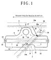
- FIG. 1 a schematic sectional view of the oil strainer according to one embodiment of the present invention is shown, together with changes of an oil surface at the time of standstill of the vehicle and at the time of an acceleration of the vehicle.
- Reference numeral 2 denotes a bottom surface of a transmission case, and the oil strainer 4 is disposed in the transmission case.
- the oil strainer 4 includes an upper case 6 provided with a communication port 8 for communication with an oil pump in a side surface of an upper part thereof, a lower case 12 which is provided with an oil suction port 14 in its lower surface and which is joined to the upper case 6, and a filter member 20 which is disposed in a space 18 formed by joining the upper and lower cases 6 and 12 and which is provided for filtering an oil flowing from the oil suction port 14 to the communication port 8.
- Both the upper case 6 and the lower case 12 are formed by resin molding.
- the upper case 6 is provided with an upper flange 10 along the outer periphery thereof
- the lower case 12 is provided with a lower flange 16 along the outer periphery thereof.
- the oil strainer 4 is produced by a method in which both the flanges 10 and 16 are clamped by a jig or jigs of a vibration welder so that the lower surface of the upper flange 10 and the upper surface of the lower flange 16 are in contact with each other, and a vibration is applied to the jig(s) of the vibration welder, whereby both the flanges 10 and 16 are integrally welded to each other.
- the filter member 20 formed by use of a non-woven fabric is clamped between both the cases 6 and 12 being joined.
- the filter member 20 is so disposed as to partition the space 18 formed by joining the upper and lower cases 6 and 12 into an upper portion and a lower portion, and the oil flowing from the oil suction port 14 to the communication port 8 is filtered by the filter member 20.
- Reference numeral 22 denotes an oil suction port cover member, by which the oil sucked in through the oil suction port 14 is conducted to the filter member 20.
- Broken line arrow 24 indicates the flow of the oil.
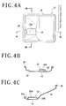
- the oil suction port cover member 22 is formed as shown in FIGS. 3 and 4 .
- FIG. 3 shows a perspective view of the lower case 12
- FIG. 4(A) shows a plan view of the lower case 12.
- FIG. 4(B) is a sectional view taken along line 4B-4B of FIG. 4(A)
- FIG. 4(C) is a sectional view taken along line 4C-4C of FIG. 4(A) .
- the oil suction port cover member 22 is formed by integrally connecting an upper wall 22a and left and right walls 22b, 22c, and a aperture part 23 is opened in the forward vehicle running direction.
- the oil suction port cover member 22 is integrally molded at the time of molding the lower case 12 from a resin mold.
- reference numeral 14a denotes an end position of the oil suction port 14 in the direction in which the oil is conducted by the oil suction port cover member 22.
- Reference numeral 26 denotes an oil surface at the time of standstill of the vehicle
- reference numeral 28 denotes an oil surface at the time of a maximum acceleration of the vehicle.
- reference numeral 26a denotes an oil surface at the time of standstill of the vehicle in the case where an oil strainer according to the related art is used
- reference numeral 28a denotes an oil surface at the time of a maximum acceleration of the vehicle in that case.
- the oil surface is changed from the standstill oil surface 26 as indicated by arrow 30.
- the total amount of oil in the transmission required can be reduced as compared with that in the related art; therefore, the oil surface at the time of vehicle standstill is lowered as indicated by arrow 27, and the oil surface at the time of a maximum vehicle acceleration is changed as indicated by arrow 29.
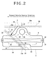
- FIG. 2 is a sectional view of the oil strainer, showing the change of the oil surface at the time of a maximum vehicle deceleration in comparison with the oil surface in the oil strainer according to the related art. While the oil surface 26 at the time of vehicle standstill is the same as in FIG. 1 , the oil surface is changed from the standstill oil surface 26 as indicated by arrow 34 at the time of a maximum vehicle deceleration, whereon the oil surface is as denoted by reference numeral 32.
- Reference numeral 32a denotes an oil surface at the time of a maximum deceleration in the case where an oil strainer according to the related art is used. According to this embodiment, the oil surface 32 at the time of the maximum deceleration is changed as indicated by arrow 33 from the oil surface 32a in the related art.
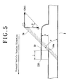
- FIG. 5 shows an oil surface at the time of a maximum vehicle acceleration
- FIG. 6 shows an oil surface at the time of a maximum vehicle deceleration
- FIG. 7 shows the oil surfaces at the times of the maximum vehicle acceleration and the maximum vehicle deceleration.
- the height h of the oil suction port cover member 22 is determined taking into account the aeration toughness based on the positional relationship between the lower case 12 of the oil strainer 4 and the filter member 20, while securing a passage area of not less than the area of the oil suction port 14.
- both the end position 14a of the oil suction port 14 in the direction in which the oil is conducted by the oil suction port cover member 22 and the total amount of oil in the transmission are determined so that the end position 14a of the oil suction port 14 is located substantially at the intersection between the oil surface 28 at the time of the maximum vehicle acceleration and the oil surface 32 at the time of the maximum vehicle deceleration.
- the oil surface can be determined by the end position 14a of the oil suction port 14 in the oil conducting direction. Therefore, the height of the oil surface can be set lower than that in the related art, the total amount of oil in the transmission can be reduced, and aeration toughness at the times of variations in the oil surface which are generated at the times of vehicle acceleration and deceleration can be enhanced.
- the tip position 22d in the oil conducting direction of the oil suction port cover member 22 is located as if advanced more in the forward vehicle running direction than the oil surface 32 at the time of the maximum vehicle deceleration, and the tip position 22d of the oil suction port cover member 22 is so set as to be immersed in the oil at the time of the maximum vehicle deceleration.
- the length 1 of the oil suction port cover member 22 shown in FIGS. 5 to 7 is so set that the tip position 22d of the oil suction port cover member 22 is immersed in the oil at the time of the maximum vehicle deceleration.
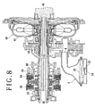
- FIG. 8 there is shown a partial longitudinal sectional view of an automatic transmission equipped with the oil strainer 4 according to the embodiment of the present invention.
- the communication port 8 of the oil strainer 4 is connected to an oil pump 46.
- the oil pump 46 is connected to a crankshaft 44 of an engine (not shown) through a case 42 of a torque converter 40, and is normally driven by the engine.
- a gear 48 is non-rotatably fixed to a main shaft 38 of the automatic transmission, and gears 50 and 52 are rotatably mounted on the main shaft 38.
- gears 50 and 52 are rotatably mounted on the main shaft 38.
- the gear 50 is fixed relative to the main shaft 38.
- gear 52 is fixed relative to the main shaft 38.
- FIG. 9 is a partial longitudinal sectional view of an automatic transmission equipped with an oil strainer 60 according to another embodiment which has an oil suction port cover member 22' characteristic of the present invention.
- the oil strainer 60 is disposed in the state of being inclined to the right or left side with reference to the forward vehicle running direction.
- An oil suction port 62 of the oil strainer 60 is covered with the oil suction port cover member 22', which is the same as that in the above-described embodiment, and a communication port 64 communicates with an oil pump 46.
- a lower part of the case of the transmission can be reduced according to the shape of the oil strainer 60, so that a further reduction in the total amount of oil in the transmission can be expected, as compared with the above-described embodiment.
- both the end position 14a of the oil suction port 14 in the direction in which the oil is conducted by the oil suction port cover member 22 and the total amount of oil in the transmission can be so determined that the end position 14a of the oil suction port 14 is located substantially at the intersection between the oil surface 28 at the time of a maximum vehicle acceleration and the oil surface 32 at the time of a maximum vehicle deceleration. This makes it possible to lower, as much as possible, the height of the oil surface, and to reduce the total amount of oil in the transmission.
- the aperture of the oil suction port cover member 22 may be set to face toward the rear side of the vehicle.
- the tip position in the oil conducting direction of the oil suction port cover member is located as if advanced more in the direction (toward the rear side of the vehicle) opposite to the forward vehicle running direction than the oil surface at the time of a maximum vehicle acceleration, and the tip position of the oil suction port cover member is so set as to be immersed in the oil at the time of the maximum vehicle acceleration.
Landscapes
- Chemical & Material Sciences (AREA)
- Chemical Kinetics & Catalysis (AREA)
- General Details Of Gearings (AREA)
Claims (3)
- Véhicule comprenant un boîtier de transmission (2) dans lequel une crépine (4) est disposée, la crépine (4) comprenant :un boîtier supérieur constitué de résine (6) qui est doté d'un orifice de communication (8) pour communiquer avec une pompe dans une surface latérale d'une partie supérieure de ce dernier et qui a une bride supérieure (10) au niveau d'une périphérie externe de ce dernier,un boîtier inférieur constitué de résine (12) qui est doté d'un orifice d'aspiration d'huile (14) dans une surface inférieure de ce dernier et qui a une bride inférieure (16) reliée à ladite bride supérieure (10) dudit boîtier supérieur (6), etun organe de filtre (20) qui est disposé dans un espace (18) formé en reliant lesdits boîtiers supérieur et inférieur (6, 12) et qui filtre une huile s'écoulant dudit orifice d'aspiration d'huile (14) vers ledit orifice de communication (8),un organe de capot d'orifice d'aspiration d'huile (22) qui est formé de façon à couvrir au moins une surface supérieure interne dudit orifice d'aspiration d'huile (14) et qui forme un passage pour conduire ladite huile vers ledit organe de filtre (20),dans lequel ledit organe de capot d'orifice d'aspiration d'huile (22) est formé de façon à couvrir les côtés gauche et droit et le côté arrière dudit orifice d'aspiration d'huile (14) ou les côtés gauche et droit et le côté avant dudit orifice d'aspiration d'huile (14), tel que vu le long de la direction de déplacement vers l'avant du véhicule, et dans lequel à la fois une position finale (14a) dudit orifice d'aspiration d'huile (14) dans la direction permettant de guider ladite huile par ledit organe de capot d'orifice d'aspiration d'huile (22) et la quantité totale de ladite huile dans ladite transmission sont déterminées de sorte que ladite position finale (14a) dudit orifice d'aspiration d'huile (14) est situées sensiblement au niveau de l'intersection entre une surface d'huile (28) au moment d'une accélération maximale du véhicule et une surface d'huile (28) au moment d'une décélération maximale du véhicule.
- Véhicule selon la revendication 1, dans lequel ledit organe de capot d'orifice d'aspiration d'huile (22) est ouvert dans la direction de déplacement vers l'avant du véhicule, une position d'extrémité (22d) dudit organe de capot d'orifice d'aspiration d'huile (22) dans ladite direction de guidage d'huile est située comme si elle était plus avancée dans ladite direction de déplacement vers l'avant du véhicule que ladite surface d'huile (28) au moment de ladite décélération maximale du véhicule, et
ladite position d'extrémité (22d) dudit organe de capot d'orifice d'aspiration d'huile (22) est réglée de façon à être immergée dans ladite huile au moment de ladite décélération maximale du véhicule. - Véhicule selon la revendication 1, dans lequel ledit organe de capot d'orifice d'aspiration d'huile (22) est ouvert dans une direction opposée à ladite direction de déplacement vers l'avant du véhicule, une position d'extrémité (22d) dudit organe de capot d'orifice d'aspiration d'huile (22) dans ladite direction de guidage d'huile est située comme si elle était plus avancée dans ladite direction de déplacement vers l'avant du véhicule que ladite surface d'huile au moment de ladite accélération maximale du véhicule, et ladite position d'extrémité (22d) dudit organe de capot d'orifice d'aspiration d'huile (22) est établie de façon à être immergée dans ladite huile au moment de ladite accélération maximale du véhicule.
Applications Claiming Priority (2)
| Application Number | Priority Date | Filing Date | Title |
|---|---|---|---|
| JP2006127584 | 2006-05-01 | ||
| PCT/JP2007/057235 WO2007129514A1 (fr) | 2006-05-01 | 2007-03-30 | Crepine de transmission |
Publications (3)
| Publication Number | Publication Date |
|---|---|
| EP2014955A1 EP2014955A1 (fr) | 2009-01-14 |
| EP2014955A4 EP2014955A4 (fr) | 2011-09-07 |
| EP2014955B1 true EP2014955B1 (fr) | 2012-12-05 |
Family
ID=38667624
Family Applications (1)
| Application Number | Title | Priority Date | Filing Date |
|---|---|---|---|
| EP07740671A Expired - Fee Related EP2014955B1 (fr) | 2006-05-01 | 2007-03-30 | Crepine de transmission |
Country Status (4)
| Country | Link |
|---|---|
| US (1) | US20090127174A1 (fr) |
| EP (1) | EP2014955B1 (fr) |
| JP (1) | JP5179871B2 (fr) |
| WO (1) | WO2007129514A1 (fr) |
Families Citing this family (10)
| Publication number | Priority date | Publication date | Assignee | Title |
|---|---|---|---|---|
| US8486277B1 (en) * | 2006-06-28 | 2013-07-16 | Sonnax Industries, Inc. | Internal bypass filtration circuit |
| JP5336045B2 (ja) * | 2007-01-10 | 2013-11-06 | 株式会社ニフコ | 燃料用フィルタ装置 |
| DE102007023641B4 (de) * | 2007-05-22 | 2015-04-02 | Ibs Filtran Kunststoff-/ Metallerzeugnisse Gmbh | Ölfiltervorrichtung |
| US20090139922A1 (en) * | 2007-12-04 | 2009-06-04 | Gm Global Technology Operations, Inc. | Transmission Filter System |
| DE102008027662A1 (de) * | 2008-06-10 | 2009-12-17 | Ibs Filtran Kunststoff- / Metallerzeugnisse Gmbh | Ölwanne mit Ölfilter |
| JP5274435B2 (ja) | 2009-11-26 | 2013-08-28 | ジヤトコ株式会社 | オイルストレーナにおけるエア溜まり防止構造 |
| JP5609237B2 (ja) * | 2010-04-26 | 2014-10-22 | トヨタ紡織株式会社 | 自動変速機用流体フィルタ |
| JP6114240B2 (ja) * | 2014-08-20 | 2017-04-12 | トヨタ自動車株式会社 | 車両用変速機 |
| US9410609B1 (en) * | 2015-09-29 | 2016-08-09 | Borgwarner Inc. | Passively fed bypass filter for splash lubrication |
| CN109306884A (zh) * | 2017-07-28 | 2019-02-05 | 福特环球技术公司 | 具有结合的滤油器的油底壳组件 |
Citations (1)
| Publication number | Priority date | Publication date | Assignee | Title |
|---|---|---|---|---|
| JPS5881305U (ja) * | 1981-11-30 | 1983-06-02 | スズキ株式会社 | エンジンの潤滑オイル吸入口 |
Family Cites Families (24)
| Publication number | Priority date | Publication date | Assignee | Title |
|---|---|---|---|---|
| JPS58181305U (ja) * | 1982-05-28 | 1983-12-03 | 吉田工業株式会社 | コンパクト容器 |
| JP2717271B2 (ja) * | 1988-07-25 | 1998-02-18 | アイシン・エィ・ダブリュ株式会社 | 自動変速機用オイルストレーナ、並びにそれを用いた自動変速機 |
| US4995971A (en) * | 1989-08-07 | 1991-02-26 | Ford Motor Company | Dual purpose automatic transmission oil pan |
| JPH0754683Y2 (ja) * | 1989-09-30 | 1995-12-18 | スズキ株式会社 | 変速機のオイルストレーナ構造 |
| JPH03157110A (ja) * | 1989-11-15 | 1991-07-05 | Aisin Aw Co Ltd | オイルストレーナ装置 |
| JPH084886A (ja) * | 1994-06-23 | 1996-01-12 | Nok Corp | 自動変速装置用流体フィルタ装置 |
| DE19626212C2 (de) * | 1996-06-29 | 1998-04-23 | Luk Fahrzeug Hydraulik | Ölsaugfilter |
| US6293420B1 (en) * | 1997-07-25 | 2001-09-25 | Kautex Textron Gmbh & Co., Kg. | Fuel tank |
| US6616836B1 (en) * | 1997-07-29 | 2003-09-09 | Dana Corporation | Filter element for oil pans and filter element/oil pan combination |
| JP2001028145A (ja) * | 1999-07-13 | 2001-01-30 | Toshiba Corp | 光学ヘッド装置及びディスク録再装置 |
| JP3420541B2 (ja) | 1999-10-22 | 2003-06-23 | 本田技研工業株式会社 | オイルストレーナ |
| JP4375698B2 (ja) | 2001-03-19 | 2009-12-02 | トヨタ紡織株式会社 | 自動変速機用オイルフィルタ装置 |
| JP4317347B2 (ja) * | 2001-04-27 | 2009-08-19 | 日本バイリーン株式会社 | 自動変速機用オイルフィルタの濾過材 |
| US7087160B2 (en) * | 2003-05-29 | 2006-08-08 | Spx Corporation | Outside-in flow engine and transmission filter and method |
| US6821422B1 (en) * | 2003-06-13 | 2004-11-23 | Ti Group Automotive Systems, L.L.C. | Strainer assembly |
| JP4405206B2 (ja) * | 2003-08-08 | 2010-01-27 | 株式会社Roki | 仕切り部材付きケース |
| JP4608859B2 (ja) * | 2003-08-26 | 2011-01-12 | 株式会社デンソー | 自動変速機の油圧制御装置 |
| JP2005291408A (ja) * | 2004-04-01 | 2005-10-20 | Honda Motor Co Ltd | オイルストレーナ |
| JP4381913B2 (ja) * | 2004-07-23 | 2009-12-09 | 本田技研工業株式会社 | 燃料タンク装置 |
| US7182869B2 (en) * | 2004-10-07 | 2007-02-27 | Ti Group Automotive Systems, L.L.C. | Fuel filter arrangement |
| DE102005027920A1 (de) * | 2005-06-16 | 2006-12-28 | Ibs Filtran Kunststoff-/ Metallerzeugnisse Gmbh | Filtervorrichtung |
| US8899266B2 (en) * | 2007-02-14 | 2014-12-02 | GM Global Technology Operations LLC | Fluid displacement reservoir |
| DE102007023641B4 (de) * | 2007-05-22 | 2015-04-02 | Ibs Filtran Kunststoff-/ Metallerzeugnisse Gmbh | Ölfiltervorrichtung |
| US20090139922A1 (en) * | 2007-12-04 | 2009-06-04 | Gm Global Technology Operations, Inc. | Transmission Filter System |
-
2007
- 2007-03-30 JP JP2007530523A patent/JP5179871B2/ja not_active Expired - Fee Related
- 2007-03-30 EP EP07740671A patent/EP2014955B1/fr not_active Expired - Fee Related
- 2007-03-30 WO PCT/JP2007/057235 patent/WO2007129514A1/fr active Application Filing
-
2008
- 2008-10-31 US US12/262,839 patent/US20090127174A1/en not_active Abandoned
Patent Citations (1)
| Publication number | Priority date | Publication date | Assignee | Title |
|---|---|---|---|---|
| JPS5881305U (ja) * | 1981-11-30 | 1983-06-02 | スズキ株式会社 | エンジンの潤滑オイル吸入口 |
Also Published As
| Publication number | Publication date |
|---|---|
| JP5179871B2 (ja) | 2013-04-10 |
| US20090127174A1 (en) | 2009-05-21 |
| EP2014955A4 (fr) | 2011-09-07 |
| WO2007129514A1 (fr) | 2007-11-15 |
| EP2014955A1 (fr) | 2009-01-14 |
| JPWO2007129514A1 (ja) | 2009-09-17 |
Similar Documents
| Publication | Publication Date | Title |
|---|---|---|
| EP2014955B1 (fr) | Crepine de transmission | |
| KR101576298B1 (ko) | 오일 팬 | |
| US5050447A (en) | Oil reservoir device for an automatic transmission | |
| EP2278191B1 (fr) | Transmission d'engrenage avec une pompe à lubrifiant et un réservoir à lubrifiant | |
| US8899266B2 (en) | Fluid displacement reservoir | |
| US9927019B2 (en) | Power unit | |
| US9109476B2 (en) | Lubricating device for power unit | |
| JP5045369B2 (ja) | オイル吸入装置 | |
| JP4645571B2 (ja) | 動力伝達装置 | |
| US9869243B2 (en) | Internal combustion engine for vehicle | |
| JPS6320607Y2 (fr) | ||
| CN102029902A (zh) | 车辆用自动变速器 | |
| JP6554132B2 (ja) | 樹脂ケース | |
| JP4563880B2 (ja) | 並列複数気筒エンジン | |
| US20180283533A1 (en) | Control device unit installation structure for transmission | |
| US11226032B2 (en) | Air vent structure of oil pump for automatic transmission, and method for assembling air vent structure | |
| EP1099614A2 (fr) | Réservoir en résine pour fluide de direction assistée | |
| JP7479756B2 (ja) | 変速機 | |
| JP4759477B2 (ja) | 変速機ハウジング | |
| JP7249937B2 (ja) | トランスアクスル | |
| JP5227821B2 (ja) | オイルパン | |
| JP4876014B2 (ja) | 潤滑装置 | |
| JP2005291408A (ja) | オイルストレーナ | |
| JP7002394B2 (ja) | 車両用動力伝達装置のオイルストレーナ | |
| JPS5811965Y2 (ja) | 車輌用油圧作動式変速機におけるオイル供給装置 |
Legal Events
| Date | Code | Title | Description |
|---|---|---|---|
| PUAI | Public reference made under article 153(3) epc to a published international application that has entered the european phase |
Free format text: ORIGINAL CODE: 0009012 |
|
| 17P | Request for examination filed |
Effective date: 20081024 |
|
| AK | Designated contracting states |
Kind code of ref document: A1 Designated state(s): AT BE BG CH CY CZ DE DK EE ES FI FR GB GR HU IE IS IT LI LT LU LV MC MT NL PL PT RO SE SI SK TR |
|
| AX | Request for extension of the european patent |
Extension state: AL BA HR MK RS |
|
| DAX | Request for extension of the european patent (deleted) | ||
| RBV | Designated contracting states (corrected) |
Designated state(s): DE GB |
|
| A4 | Supplementary search report drawn up and despatched |
Effective date: 20110804 |
|
| RIC1 | Information provided on ipc code assigned before grant |
Ipc: F16H 57/02 20060101ALI20110729BHEP Ipc: F16H 57/04 20100101AFI20110729BHEP Ipc: B01D 35/02 20060101ALI20110729BHEP Ipc: B01D 35/30 20060101ALI20110729BHEP |
|
| 17Q | First examination report despatched |
Effective date: 20110818 |
|
| RIC1 | Information provided on ipc code assigned before grant |
Ipc: B01D 35/027 20060101ALI20120525BHEP Ipc: F16H 57/04 20100101AFI20120525BHEP |
|
| GRAP | Despatch of communication of intention to grant a patent |
Free format text: ORIGINAL CODE: EPIDOSNIGR1 |
|
| RIN1 | Information on inventor provided before grant (corrected) |
Inventor name: TSUBATA, YOSHIMICHI C/O HONDA R&D CO., LTD. Inventor name: TAKEI, SUSUMU C/O HONDA R&D CO., LTD. Inventor name: SHINBORI, ISAMU C/O HONDA R&D CO., LTD. |
|
| GRAS | Grant fee paid |
Free format text: ORIGINAL CODE: EPIDOSNIGR3 |
|
| GRAA | (expected) grant |
Free format text: ORIGINAL CODE: 0009210 |
|
| AK | Designated contracting states |
Kind code of ref document: B1 Designated state(s): DE GB |
|
| REG | Reference to a national code |
Ref country code: GB Ref legal event code: FG4D |
|
| REG | Reference to a national code |
Ref country code: DE Ref legal event code: R096 Ref document number: 602007027148 Country of ref document: DE Effective date: 20130131 |
|
| PLBE | No opposition filed within time limit |
Free format text: ORIGINAL CODE: 0009261 |
|
| STAA | Information on the status of an ep patent application or granted ep patent |
Free format text: STATUS: NO OPPOSITION FILED WITHIN TIME LIMIT |
|
| 26N | No opposition filed |
Effective date: 20130906 |
|
| REG | Reference to a national code |
Ref country code: DE Ref legal event code: R097 Ref document number: 602007027148 Country of ref document: DE Effective date: 20130906 |
|
| REG | Reference to a national code |
Ref country code: DE Ref legal event code: R084 Ref document number: 602007027148 Country of ref document: DE |
|
| REG | Reference to a national code |
Ref country code: GB Ref legal event code: 746 Effective date: 20141114 |
|
| REG | Reference to a national code |
Ref country code: DE Ref legal event code: R084 Ref document number: 602007027148 Country of ref document: DE Effective date: 20141120 |
|
| PGFP | Annual fee paid to national office [announced via postgrant information from national office to epo] |
Ref country code: DE Payment date: 20180320 Year of fee payment: 12 Ref country code: GB Payment date: 20180329 Year of fee payment: 12 |
|
| REG | Reference to a national code |
Ref country code: DE Ref legal event code: R119 Ref document number: 602007027148 Country of ref document: DE |
|
| GBPC | Gb: european patent ceased through non-payment of renewal fee |
Effective date: 20190330 |
|
| PG25 | Lapsed in a contracting state [announced via postgrant information from national office to epo] |
Ref country code: DE Free format text: LAPSE BECAUSE OF NON-PAYMENT OF DUE FEES Effective date: 20191001 Ref country code: GB Free format text: LAPSE BECAUSE OF NON-PAYMENT OF DUE FEES Effective date: 20190330 |