EP2012282A2 - Spielautomat - Google Patents
Spielautomat Download PDFInfo
- Publication number
- EP2012282A2 EP2012282A2 EP08010810A EP08010810A EP2012282A2 EP 2012282 A2 EP2012282 A2 EP 2012282A2 EP 08010810 A EP08010810 A EP 08010810A EP 08010810 A EP08010810 A EP 08010810A EP 2012282 A2 EP2012282 A2 EP 2012282A2
- Authority
- EP
- European Patent Office
- Prior art keywords
- cabinet
- gaming machine
- game
- speakers
- pair
- Prior art date
- Legal status (The legal status is an assumption and is not a legal conclusion. Google has not performed a legal analysis and makes no representation as to the accuracy of the status listed.)
- Withdrawn
Links
- 210000005069 ears Anatomy 0.000 claims description 6
- 210000000707 wrist Anatomy 0.000 description 10
- 230000000694 effects Effects 0.000 description 6
- UFULAYFCSOUIOV-UHFFFAOYSA-N cysteamine Chemical compound NCCS UFULAYFCSOUIOV-UHFFFAOYSA-N 0.000 description 5
- 238000012423 maintenance Methods 0.000 description 5
- 238000001514 detection method Methods 0.000 description 2
- 238000010586 diagram Methods 0.000 description 2
- 238000007689 inspection Methods 0.000 description 2
- 238000009434 installation Methods 0.000 description 2
- 239000004973 liquid crystal related substance Substances 0.000 description 2
- VYZAMTAEIAYCRO-UHFFFAOYSA-N Chromium Chemical compound [Cr] VYZAMTAEIAYCRO-UHFFFAOYSA-N 0.000 description 1
- NIXOWILDQLNWCW-UHFFFAOYSA-N acrylic acid group Chemical group C(C=C)(=O)O NIXOWILDQLNWCW-UHFFFAOYSA-N 0.000 description 1
- 229920000122 acrylonitrile butadiene styrene Polymers 0.000 description 1
- 230000009286 beneficial effect Effects 0.000 description 1
- 235000019504 cigarettes Nutrition 0.000 description 1
- 210000004247 hand Anatomy 0.000 description 1
- 238000010030 laminating Methods 0.000 description 1
- 238000004519 manufacturing process Methods 0.000 description 1
- 239000002184 metal Substances 0.000 description 1
- 238000012986 modification Methods 0.000 description 1
- 230000004048 modification Effects 0.000 description 1
- 230000002093 peripheral effect Effects 0.000 description 1
- 229920003023 plastic Polymers 0.000 description 1
- 230000035939 shock Effects 0.000 description 1
- 230000008961 swelling Effects 0.000 description 1
Images


Classifications
-
- G—PHYSICS
- G07—CHECKING-DEVICES
- G07F—COIN-FREED OR LIKE APPARATUS
- G07F17/00—Coin-freed apparatus for hiring articles; Coin-freed facilities or services
- G07F17/32—Coin-freed apparatus for hiring articles; Coin-freed facilities or services for games, toys, sports, or amusements
-
- G—PHYSICS
- G07—CHECKING-DEVICES
- G07F—COIN-FREED OR LIKE APPARATUS
- G07F17/00—Coin-freed apparatus for hiring articles; Coin-freed facilities or services
- G07F17/32—Coin-freed apparatus for hiring articles; Coin-freed facilities or services for games, toys, sports, or amusements
- G07F17/3202—Hardware aspects of a gaming system, e.g. components, construction, architecture thereof
- G07F17/3216—Construction aspects of a gaming system, e.g. housing, seats, ergonomic aspects
Definitions
- the present invention relates to a gaming machine such as a slot machine, in which a gaming medium (a gaming value) such as a coin is used to play a game and a gaming value such as credit is provided to a player.
- a gaming medium a gaming value
- a gaming value such as credit
- a slot machine as a gaming machine includes: a cabinet with an opening to store a reel unit and the like therein; a front door to open and close the opening; and a display device to display information related to the game.
- the front door has an operation table that allows a player to perform operation for the gaming machine, and decorative lamps to perform gaming modes and speakers to produce sounds related to the game
- a pair of speakers is preferably arranged so that lines connecting each of the speakers and a player form an equilateral triangle.
- the speakers have been thus arranged on both sides of the gaming machine (for example, refer to U.S. Patent No. 6,334,612 , hereinafter referred to as Patent Document 1).
- the speakers since the speakers must be spaced apart from each other to make the lines connecting each of the speakers and the player form an equilateral triangle, the speakers must be arranged as near to the side edges of the gaming machine as possible in view of the size of the gaming machine. Therefore, when a plurality of gaming machines is juxtaposed in a hall, the adjacent gaming machines must be arranged with a spacing therebetween corresponding to the size of the speakers projecting laterally.
- the speakers are set inside the gaming machine, the speakers are required to be arranged remotely from the player due to the operation table that projects forward from a front face of the gaming machine. In this way, these restrictions do not allow the gaming machine to provide the player with a chance to hear gaming sound effects with much presence while playing a game.
- the present invention has been made in view of the abovementioned problems.
- the present invention provides the following.
- a gaming machine which includes a cabinet, a display device, an input device, a controller, a pair of speakers, and a pair of exterior frames.
- the display device that is placed in a front face of the cabinet displays information related to a game.
- the input device allows a player to perform operation related to the game.
- the controller performs processing related to execution of the game in response to an input to the input device.
- the pair of speakers produces sound related to the game in response to a signal from the controller.
- the pair of exterior frames is placed in a height direction of the cabinet at laterally end portions of the cabinet. Each speaker is integral with each exterior frame.
- the speakers are integral with the cabinet via the exterior frames, they do not project laterally in a width direction of the gaming machine. This allows a plurality gaming machines to be juxtaposed. In addition, the speakers, which are integral with the cabinet via the exterior frames, can be easily assembled with the gaming machine.
- a gaming machine which further includes an operation table.
- the input device is placed on the operation table.
- the operation tale is configured to project forward from the cabinet.
- the pair of exterior frames is placed at laterally end portions of the operation table.
- the exterior frames are placed at the lateral end portions of the operation table, it is easy to assemble the speakers with the cabinet. Furthermore, the speakers do not cause interference with the operation performed for the input device by the player.
- a gaming machine in which the pair of speakers is placed at laterally end portions of the operation table in front of the cabinet.
- the gaming machine described above has the speakers that are placed closer to the player, the gaming machine stimulates the player by sound with much presence.
- the gaming machine can place the speakers closer to the player with the operation table that does not project excessively forward from the cabinet.
- a gaming machine in which the pair of speakers is independently controlled to produce sound by the controller.
- the gaming machine described above can provide the sound in stereo, the gaming machine allows the player to feel more excited.
- a gaming machine in which the pair of speakers is placed so as to substantially meet the height of ears of the player.
- the gaming machine described above produces sound with speakers closer to the ears of the player, the gaming machine can allow the player to enjoy the sound with much presence.
- a gaming machine which includes a cabinet, a display device, an input device, a controller, a pair of speakers, a pair of exterior frames, and an operation table.
- the display device that is placed in a front face of the cabinet displays information related to a game.
- the input device allows a player to perform operation related to the game.
- the controller performs processing related to execution of the game in response to an input to the input device.
- the pair of speakers produces sound related to the game in response to a signal from the controller.
- the pair of exterior frames is placed in a height direction of the cabinet at laterally end portions of the cabinet.
- the input device is placed on the operation table.
- the operation tale is configured to project forward from the cabinet.
- the pair of exterior frames is placed at laterally end portions of the operation table.
- Each speaker is integral with each exterior frame.
- the pair of speakers is placed at the laterally end portions of the operation table in front of the cabinet.
- the speakers integrated with the cabinet by way of the exterior frames do not project from lateral sides of the gaming machine, a plurality of gaming machines can thus be closely juxtaposed.
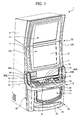
- a gaming machine 1 has: a cabinet 2; a display disposed on a front face of the cabinet 2, which displays information related to a game (a main display 4 described later); an input device for allowing a player to carry out operations related to the game (a 1-bet button 11, a 3-bet button 12, a 5-bet button 13 and a spin button 14 described later); a controller that performs operations to execute a game in response to an input to the input device; a speaker 20 for generating sound effects related to the game in response to a signal from the controller; and an exterior frame 19 installed on each side of a front face of the cabinet 2 along a height direction, in which the speaker 20 is formed integrally via the exterior frame 19. Therefore, since speakers 20 integrated with the cabinet 2 by way of exterior frames 19 do not project from lateral sides of the gaming machine 1, a plurality of gaming machines 1a and 1b can be closely juxtaposed.
- the gaming machine 1 according to the present embodiment is described hereinafter with reference to FIGS. 1 to 6 .
- a schematic configuration of the gaming machine 1 of the present embodiment is described with reference to FIG. 1 .
- FIG. 1 is a perspective view of the gaming machine 1.
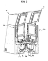
- FIG. 2 is a perspective view illustrating a front door 22 of the gaming machine 1 in an open position.
- the gaming machine 1 is an upright slot machine to be installed in game halls such as a casino, having a cabinet 2 for storing electronic and mechanical components for performing a game.
- the cabinet 2 is formed in a rectangular parallelepiped having an opening 29 in a front face thereof.
- the front door 22 that closes the opening 29 is pivotally attached to the cabinet 2 by way of a hinge 30 provided on a left side end portion of the front face of the cabinet 2.
- a sub display 3 is disposed in an upper portion of the front face of the cabinet 2, and a main display 4 is disposed in a central portion of the front face of the cabinet 2.
- the sub display 3 constituted of a liquid crystal display displays an award table, which shows odds and the like indicating an award per single medal provided for a player winning the game, while the gaming machine 1 is in a base game or a standby state.
- the sub display 3 is tilted forward with respect to the gaming machine 1 so as to be more visually beneficial to the player, whose line of sight lies substantially at a height of the main display 4. A detailed configuration of the main display 4 is described later.
- An operation table 5 which projects forward from the front face of the cabinet 2, is disposed below the main display 4.
- a CHANGE button 6, a CASH OUT button 7, and a HELP button 8 are disposed from the left.
- a coin slot 9 and a bill slot 10 are disposed on the right side of the HELP button 8.
- a 1-bet button 11, a 3-bet button 12, and a 5-bet button 13 are disposed from the left.
- a SPIN/REPEAT-bet button hereinafter referred to as a "spin button" 14 is disposed.
- the CHANGE button 6 is pressed by a player to change a bill inserted into the bill slot 10.
- the changed coins are discharged through a coin payout opening 15 to a coin tray 16 provided in a lower portion of the cabinet 2.
- a CHANGE switch is connected to the CHANGE button 6.
- the CHANGE switch When the CHANGE button 6 is pressed by a player, the CHANGE switch outputs a switch signal to a CPU device and the like, which control the gaming machine 1.
- the CASH OUT button 7 is pressed by a player at the end of a base game to cash out coins obtained in the game to the coin tray 16 through the coin payout opening 15.
- a CASH OUT switch is connected to the CASH OUT button 7. When the CASH OUT button 7 is pressed by a player, the CASH OUT switch outputs a switch signal to a CPU device and the like, which control the gaming machine 1.
- the HELP button 8 is pressed by a player when she is unfamiliar with how to play the game.
- the sub display 3 and the main display 4 display various kinds of help information.
- a HELP switch is connected to the HELP button 8.
- the HELP switch When the HELP button 8 is pressed, the HELP switch outputs a switch signal to a CPU device and the like, which control the gaming machine 1.
- the award table when an award table is not displayed on the sub display 3 during a game, the award table appears on the sub display 3 in response to the HELP button 8 pressed by a player.
- a coin sensor is disposed at the coin slot 9. When a coin is inserted into the coin slot 9, the coin sensor outputs a coin detection signal to a CPU device and the like, which control the gaming machine 1.
- a bill sensor is disposed at the bill slot 10. When a bill is inserted into the bill slot 10, the bill sensor outputs a bill detection signal to a CPU device and the like, which control the gaming machine 1.
- the 1-bet button 11 is used to bet a coin one by one and can be pressed to bet up to three times.
- a 1-bet switch is connected to the 1-bet button 11. When the 1-bet button 11 is pressed, the 1-bet switch outputs a switch signal to a CPU device and the like, which control the gaming machine 1.
- the 3-bet button 12 is pressed to start a game with 3 coins bet.
- a 3-bet switch is connected to the 3-bet button 12. When the 3-bet button 12 is pressed, the 3-bet switch outputs a switch signal to a CPU device and the like, which control the gaming machine 1.
- the 5-bet button 13 is pressed to start a game with 5 coins bet or to start a bonus game which provides a special gaming mode which is advantageous to the player.
- a 5-bet switch is connected to the 5-bet button 13. When the 5-bet button 13 is pressed, the 5-bet switch outputs a switch signal to a CPU device and the like, which control the gaming machine 1.
- the spin button 14 is used as a game start button to start a game on condition that a bet has been made by way of the bet button 11, 12 or 13.
- the spin button 14 is pressed by a player to start rotation of reels (described later) so as to execute a game with the present bet amount or the previous bet amount.
- the spin button 14, which must be pressed at the beginning of each game, is a frequently used button. Accordingly, the spin button 14 is preferably provided on the right hand side of the operation table 5 of a gaming machine 1 designed for right-handed players. On the contrary, the spin button 14 is preferably provided on the left hand side a gaming machine 1 designed for left-handed players.
- a spin switch is connected to the spin button 14. When the spin button 14 is pressed, the spin switch outputs a switch signal to a CPU device and the like, which control the gaming machine 1.
- bet amounts allowed for a player to wager by pressing the spin button 14 are 1, 2, 3, and 5.
- the coin payout opening 15 is formed and the coin tray 16 is provided, which receives coins discharged through the coin payout opening 15.
- a coin detector is provided inside the coin payout opening 15 for detecting the number of coins discharged through the coin payout opening 15.
- the main display 4 is a panel that provides a display of rotation of symbols to which a player pays continuous attention.
- the main display 4 has a transparent touch panel 31 disposed on the front face thereof and a transparent liquid crystal display, which is translucent and fixed to the front door 22 of the cabinet 2.
- Five transparent display windows (not shown) are provided on the main display 4. Behind the main display 4, five mechanical reels are disposed in parallel, and supported independently and rotatably. Each of the five reels is disposed so as to face each of the display windows formed on the main display 4.
- a plurality of kinds of symbols is arranged on an outer peripheral surface of each reel. Three symbols are externally visible through each of the display windows for each of the five mechanical reels disposed inside the cabinet 2. A plurality of pay lines (not shown) that traverses the five display windows horizontally and obliquely is also displayed on the main display 4.
- the main display 4 is tilted back to allow a player, whose line of sight lies substantially at a height of the main display 4, to turn her eyes slightly downward at the main display 4 so as to allow her to have a comfortable posture.
- the mechanical reels disposed behind the main display 4 to variably display the symbols have been described above, video reels can alternatively be displayed on the main display 4. In addition, the number of reels is not limited to 5.
- a winning combination is predetermined based on a combination of plurality of kinds of symbols.
- a combination matching a winning combination of symbols is statically displayed along a pay line, coins are discharged through the coin payout opening 15 in accordance with the winning combination.
- the symbols may alternatively be provided in other ways.
- a center line is set as a pay line.
- the pay line is displayed on the main display 4 when a player plays a game by rotating and stopping the reels by pressing the 1-bet button 11, the 3-bet button 12, or 5-bet button 13, and then pressing the spin button 14.
- the pay line disappears from the main display 4.
- a ticket printer 34 is installed on the left, below the main display 4, which outputs tickets with information in accordance with the displayed result on the main display 4.
- the operation table 5 projecting from the front face of the cabinet 2 is disposed below the ticket printer 34.
- a lower panel 17 is disposed below the operation table 5, which is a plastic panel having a printed image related to the game.
- the lower panel 17 is illuminated by way of a cold-cathode tube.
- the coin tray 16 is provided for accumulating coins paid out according to a result of the game.
- the gaming machine 1 has the front door 22 with the main display 4 and the operation table 5, and a lower front door 33 with the lower panel 17 and the coin tray 16.
- the front door 22 and the lower front door 33 are configured to swing open so as to implement better workability in opening and closing these doors 22 and 33.
- the front door 22 is provided at the front of the cabinet 2 and is supported on the left end portion of the cabinet 2 by the hinge 30. Since the front door 22 is attached to the left end portion of the cabinet 2 via the hinge 30 and the front face of the cabinet 2 is tilted back, the front door 22 can be opened not less than 90 degrees while lifting up the right portion of the front door 22.
- the lower front door 33 swings open along with the front door 22. Accordingly, a large opening 29 appears at the front of the cabinet 2. While the front door 22 is open, the reels and wiring disposed inside the cabinet 2 can undergo maintenance, and a collection box (not shown) in the cabinet 2 can be exposed. The collection box is used for collecting bills inserted through the bill slot 10. In addition, a coin hopper (not shown) is also installed in the opening 29, which accumulates the coins inserted from the coin slot 9. The coin tray 16 receives the coins that are discharged by the coin hoper as necessary.
- the coin tray 16 is fixed at the bottom end of the front face of the lower front door 33 that is mainly used for collecting bills and the like.
- the coin tray 16 extends across substantially the entire width of the lower front door 33 and accumulates the coins discharged from the coin hopper installed inside the cabinet 2.
- the front door 22 and the lower front door 33 in an open position do not interfere with the operation carried out inside the cabinet 2, thereby improving the efficiency of operation. As shown in FIGS.
- the coin tray 16 moves to a position to avoid contact with an operator while the front door 22 and the lower front door 33 are in an open position.
- the coin tray 16 is used not only to accumulate the gaming medium discharged from the gaming machine 1 such as medals, tokens, tickets and the like, but also to hold belongings of the player (for example, cigarettes and a hand bag).
- the operation table 5 is disposed in front of the cabinet 2 and below the main display 4.
- the operation table 5 laterally extends along the width direction of the front door 22.
- the operation table 5 projects forward from the front door 22, which is pivotally attached to the cabinet 2 via the hinge 30 provided on the left thereof.
- the upper face of the operation table 5 is tilted so as to make a portion closer to a player 28 lower than that closer to the cabinet 2, allowing the player 28 to lean comfortably against the operation table 5 by placing their hands thereon.
- the 1-bet button 11, the 3-bet button 12, the 5-bet button 13 and the like, which are the input device for instructing the execution of a game, are provided on the operation table 5.
- the spin button 14 is provided, which is used as a game start button to start a game under the condition that a bet has been made by the bet button 11, 12 or 13.
- a wrist rest 36 for supporting a wrist of the player 28 is provided on the right side of the operation table 5.
- the wrist rest 36 projects from the front end portion of the operation table 5 toward the player 28.
- the front end of the wrist rest 36 has a shape of a gentle arc swelling outwardly toward the player 28. Since the spin button 14, which is frequently used by the player 28 to start each game, is provided in a portion of the operation table 5 closer to the wrist rest 36, as shown in FIG. 6 , the gaming machine 1 can alleviate fatigue experienced by the player 28, allowing her to play a game for a longer time.
- a gaming machine 1 designed for right-handed players since a description has been given of the gaming machine 1 designed for right-handed players, it has the wrist rest 36 on the right portion.
- a gaming machine 1 designed for left-handed players preferably has a wrist rest 36 on the left portion of an operation table 5.
- a cutout 21 is provided on the right portion of the operation table 5, and a front door 22 is pivotally attached to a cabinet 2 via a hinge 30 disposed on the right portion of the cabinet 2.
- the lower panel 17 is provided below the operation table 5.
- the lower panel 17 is formed by laminating a film having a logo showing the name of the gaming machine and an image of characters and the like thereon, and a transparent acrylic plate.
- the lower panel 17 is disposed at a lower front face of the cabinet 2.
- a cold-cathode tube (not shown) is installed behind the lower panel 17, and light irradiated from the cold-cathode tube penetrates the lower panel 17 and lights up the logo and the image of characters and the like shown thereon. Accordingly, the image shown on the lower panel 17 becomes more visible to the audience watching the slot game from behind the player 28. In this way, the gaming machine 1 can differentiate itself from other types of gaming machines and increase its attractiveness.
- speakers 20L and 20R for generating sound effects for the game are provided at the front face of the cabinet 2, between the main display 4 and the operation
- the speakers 20L and 20R are configured to add effects for the game by generating sound relating to the game in response to a signal from a controller, and are controlled by the controller to generate sound independently from each other. Therefore, the right and left speakers 20R and 20L can produce sound with enhanced stereo effects, allowing the player to feel excited.
- Exterior frames 19L and 19R are provided on both sides of the front door 22 on the front face of the cabinet 2, along a height direction.
- the exterior frames 19L and 19R have the same length as the length from the upper end of the front door 22 to the side portion of the operation table 5.
- the exterior frames 19L and 19R are attached to be integral with both lateral end portions of the front door 22, and at the same time installed at the side portions of the operation table 5.
- the exterior frame 19R installed on the right of the front door 22 has a C-shaped speaker space 26R.
- the position of the C-shaped speaker space is arranged to lie between the main display 4 and the operation table 5.
- the C-shaped speaker space bulges out in the width direction of the front door 22.
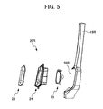
- the speaker 20R includes: a speaker body 25 for outputting sound; a speaker box 24 for housing the speaker body 25; and a speaker grill 23 provided on the front face of the speaker box 24 for protection thereof.
- the front face of the speaker body 25 is fixed to the front wall of the speaker box 24, which is fixed inside the speaker space 26 provided in the exterior frame 19R.
- the size of the speaker space 26R provided in the exterior frame 19R is substantially the same as the size of the speaker 20R.
- the speaker 20R can thus be fixed inside the speaker space 26. Therefore, the speaker 20R can easily be attached to the front door 22 by way of the exterior frame 19R.
- FIG. 5 is an exploded enlarged view of the speaker 20R disposed on the right of the cabinet 2. It should be noted that the speaker 20L disposed on the left of the cabinet 2 is similarly configured to have a mirrored image of FIG. 5 .
- the speakers 20L and 20R with the cabinet 2 by way of the exterior frames 19L and 19R, restricting the speakers 20L and 20R from projecting too much from the sides of the gaming machine 1.
- This allows a plurality of gaming machines 1 to be closely juxtaposed in a hall and the like. In this way, it is possible to save spacing between the adjacent gaming machines 1, thereby increasing the number of gaming machines 1 installed in a given installation area.
- the speakers 20L and 20R can be protected by the exterior frames 19L and 19R, it is possible to protect the speakers 20L and 20R from possible damage during transportation of the gaming machine 1.
- the exterior frames 19L and 19R which are formed of sheet metal and a chrome plated ABS resin disposed thereon, have high stiffness. In case a foreign object hits the gaming machine 1 during transportation and the like, the exterior frames 19L and 19R protect the speakers 20L and 20R installed in the speaker spaces 26L and 26R from shock, thereby preventing damage to the speakers 20L and 20R. In addition, the exterior frames 19L and 19R with high stiffness prevent a malicious person who tries forcefully open the exterior frames 19L and 19R from damaging the gaming machine 1.
- the exterior frames 19L and 19R extend from the upper end of the front door 22 to both sides of the operation table 5.
- the speaker spaces 26L and 26R provided in the exterior frames 19L and 19R are arranged so as to lie between the main display 4 and the operation table 5.
- the speaker spaces 26L and 26R arranged to lie at the front of the front door 22 and at the side portions of the operation table 5.
- the speakers 20L and 20R are arranged to lie at the front face of the cabinet 2, they are allowed to be closer to the player 28 compared to when they are disposed on the side faces of the cabinet 2. In this way, the speakers 20L and 20R produce sound with presence that stimulates the player 28. Also, the close location of the speakers 20L and 20R relative to the player 28, which is implemented without causing the operation table 5 to project forward too much, contributes the production of sound with presence.
- the speakers 20L and 20R are arranged to be parallel to the main display 4 at the front of the cabinet 2. Front faces of the speakers 20L and 20R are tilted back so as to be oriented toward the ears of the player. This can orient the sound of the speakers to the player and improve sound effects.
- the speakers 20L and 20R integrated with the front door 22 via the exterior frames 19L and 19R, move integrally with the front door 22.
- the speakers 20L and 20R are arranged to lie substantially at the height of the ears of the player 28, sound with more presence can be provided to the player, because the sound is produced at a position closer to the ears of the player.
- the description is focused on a relation between a cutout 21a of the first gaming machine 1a and an operation table 5b of the second gaming machine 1b, while a front door 22a of the first gaming machine 1a is an open position.
- FIG. 3 is a diagram illustrating the front door 22a in an open position of the first gaming machine 1a that is juxtaposed with the second gaming machine 1b.
- FIG. 4 is an enlarged view of the operation tables 5a and 5b of FIG. 3 .
- the front door 22a can be opened, which pivots about a hinge provided on the left of the front door 22a.
- the cutout 21a on the left of the operation table 5a of the first gamine machine 1a is likely to collide with the right end of a wrist rest 36b on the right of the operation table 5b of the second gaming machine 1b. Since a curved recess provided by the cutout 21a avoids interference with the wrist rest 36b, and the cutout 21a of the first gaming machine 1a is spaced a given distance from the wrist rest 36b of the adjacent second gaming machine 1b, the front door 22a of the first gaming machine 1a can be opened enough to perform easy maintenance inside the cabinet. Furthermore, since this can save spacing between the adjacent gaming machines 1a and 1b, it is possible to increase the number of gaming machines 1 that can be installed in a given area available for installation.
Landscapes
- Physics & Mathematics (AREA)
- General Physics & Mathematics (AREA)
- Slot Machines And Peripheral Devices (AREA)
- Pinball Game Machines (AREA)
Applications Claiming Priority (1)
| Application Number | Priority Date | Filing Date | Title |
|---|---|---|---|
| JP2007160631A JP2008307334A (ja) | 2007-06-18 | 2007-06-18 | 遊技機 |
Publications (2)
| Publication Number | Publication Date |
|---|---|
| EP2012282A2 true EP2012282A2 (de) | 2009-01-07 |
| EP2012282A3 EP2012282A3 (de) | 2009-12-23 |
Family
ID=39710940
Family Applications (1)
| Application Number | Title | Priority Date | Filing Date |
|---|---|---|---|
| EP08010810A Withdrawn EP2012282A3 (de) | 2007-06-18 | 2008-06-13 | Spielautomat |
Country Status (5)
| Country | Link |
|---|---|
| US (1) | US20080311987A1 (de) |
| EP (1) | EP2012282A3 (de) |
| JP (1) | JP2008307334A (de) |
| AU (1) | AU2008202570A1 (de) |
| ZA (1) | ZA200805220B (de) |
Families Citing this family (30)
| Publication number | Priority date | Publication date | Assignee | Title |
|---|---|---|---|---|
| JP2008307335A (ja) * | 2007-06-18 | 2008-12-25 | Aruze Corp | 遊技機 |
| USD615598S1 (en) * | 2009-02-17 | 2010-05-11 | Spec International, Inc. | Gaming machine cabinet |
| CA2681684A1 (en) * | 2009-10-06 | 2011-04-06 | Jvl Corporation | Game terminal |
| US20110269543A1 (en) | 2010-04-28 | 2011-11-03 | Igt | Projection Button |
| JP5800372B2 (ja) * | 2013-07-29 | 2015-10-28 | 株式会社ディ・ライト | 遊技機 |
| DE102014008159A1 (de) * | 2014-05-30 | 2015-12-03 | Novomatic Ag | Gerät mit einem einem Handgriff zugeordneten Bedienelement |
| CA161944S (en) * | 2014-12-22 | 2016-01-20 | Adp Gauselmann Gmbh | Gaming machine housing |
| USD820915S1 (en) | 2015-09-22 | 2018-06-19 | Ags Llc | Gaming machine |
| USD813954S1 (en) | 2015-09-24 | 2018-03-27 | Ags Llc | Game tower |
| USD803324S1 (en) * | 2015-09-26 | 2017-11-21 | Everi Games Inc. | Gaming machine |
| USD818048S1 (en) * | 2015-10-05 | 2018-05-15 | Ags Llc | Gaming machine |
| US9997010B2 (en) | 2015-12-18 | 2018-06-12 | Ags Llc | Electronic gaming device with external lighting functionality |
| US10002488B2 (en) | 2015-12-17 | 2018-06-19 | Ags Llc | Electronic gaming device with call tower functionality |
| USD803323S1 (en) * | 2016-01-11 | 2017-11-21 | Everi Games Inc. | Gaming machine with topper monitor |
| USD864305S1 (en) * | 2017-01-16 | 2019-10-22 | ZITRO IP S.àr.l. | Gaming machine desk top terminal |
| USD843473S1 (en) | 2017-04-07 | 2019-03-19 | Ags Llc | Gaming machine |
| USD865873S1 (en) | 2017-08-23 | 2019-11-05 | Ags Llc | Gaming machine |
| USD854620S1 (en) * | 2017-08-30 | 2019-07-23 | Entropy Cabinet Solutions Co., Ltd. | Gaming machine |
| USD852890S1 (en) | 2017-11-30 | 2019-07-02 | Ags Llc | Gaming machine |
| JP6526269B2 (ja) * | 2018-01-31 | 2019-06-05 | 株式会社ディ・ライト | 遊技機 |
| US10901253B2 (en) | 2018-10-02 | 2021-01-26 | Aristocrat Technologies Australia Pty Limited | Button deck assembly for an electronic gaming machine and method for making the same |
| US11288912B2 (en) | 2020-03-04 | 2022-03-29 | Aristocrat Technologies, Inc. | Electronic gaming machine including hybrid virtual and physical button area |
| USD1029942S1 (en) * | 2020-04-14 | 2024-06-04 | Aristocrat Technologies, Inc. (ATI) | Gaming machine |
| USD990577S1 (en) | 2021-09-28 | 2023-06-27 | Igt | Gaming machine |
| USD986978S1 (en) | 2021-09-29 | 2023-05-23 | Everi Games, Inc. | Gaming machine |
| USD1032722S1 (en) | 2022-04-19 | 2024-06-25 | Ags Llc | Gaming machine |
| USD1032723S1 (en) | 2022-04-19 | 2024-06-25 | Ags Llc | Gaming machine |
| USD990574S1 (en) * | 2022-05-02 | 2023-06-27 | Igt | Gaming machine |
| USD1105254S1 (en) | 2023-04-18 | 2025-12-09 | Ags Llc | Gaming machine |
| USD1074823S1 (en) * | 2023-08-14 | 2025-05-13 | Igt | Gaming machine |
Citations (2)
| Publication number | Priority date | Publication date | Assignee | Title |
|---|---|---|---|---|
| US6334612B1 (en) | 1999-11-17 | 2002-01-01 | Wms Gaming Inc. | Ergonomically-designed gaming machine |
| JP2007160631A (ja) | 2005-12-12 | 2007-06-28 | Canon Inc | 画像記録装置 |
Family Cites Families (30)
| Publication number | Priority date | Publication date | Assignee | Title |
|---|---|---|---|---|
| AUPP272698A0 (en) * | 1998-03-31 | 1998-04-23 | Lake Dsp Pty Limited | Soundfield playback from a single speaker system |
| JP2001079139A (ja) * | 1999-09-17 | 2001-03-27 | Aruze Corp | スロットマシン |
| JP3831695B2 (ja) * | 2002-09-11 | 2006-10-11 | 株式会社コナミデジタルエンタテインメント | ゲームシステム及びサーバ装置 |
| US20040072610A1 (en) * | 2002-10-11 | 2004-04-15 | Rick White | Gaming machine and method having symbols capable of displaying movement |
| JP4443104B2 (ja) * | 2002-11-18 | 2010-03-31 | 株式会社ユニバーサルエンターテインメント | 遊技機 |
| US20040142747A1 (en) * | 2003-01-16 | 2004-07-22 | Pryzby Eric M. | Selectable audio preferences for a gaming machine |
| US7367886B2 (en) * | 2003-01-16 | 2008-05-06 | Wms Gaming Inc. | Gaming system with surround sound |
| US7922583B2 (en) * | 2003-08-05 | 2011-04-12 | Igt | Digital signal processor based generation and control of electronic signals in a gaming machine |
| US7758429B2 (en) * | 2003-09-03 | 2010-07-20 | Igt | Articulated player tracking panel |
| US20050130731A1 (en) * | 2003-12-10 | 2005-06-16 | Englman Allon G. | Gaming machine having an enhanced game play scheme |
| US8113517B2 (en) * | 2004-07-30 | 2012-02-14 | Wms Gaming Inc. | Gaming machine chair |
| JP2006051711A (ja) * | 2004-08-12 | 2006-02-23 | Sumitomo Rubber Ind Ltd | タイヤ用ゴム部材の製造方法。 |
| US20060068908A1 (en) * | 2004-09-30 | 2006-03-30 | Pryzby Eric M | Crosstalk cancellation in a wagering game system |
| US20080070685A1 (en) * | 2004-09-30 | 2008-03-20 | Pryzby Eric M | Audio Object Location in a Computerized Wagering Game |
| US20060068909A1 (en) * | 2004-09-30 | 2006-03-30 | Pryzby Eric M | Environmental audio effects in a computerized wagering game system |
| JP2006218043A (ja) * | 2005-02-09 | 2006-08-24 | Aruze Corp | タイピングゲーム装置 |
| US20060189391A1 (en) * | 2005-01-31 | 2006-08-24 | Bird John M | Gaming machine system and method |
| JP4697855B2 (ja) * | 2005-02-22 | 2011-06-08 | 株式会社ユニバーサルエンターテインメント | 遊技機 |
| US20060199645A1 (en) * | 2005-02-28 | 2006-09-07 | Canterbury Stephen A | Wagering game with streaming usb audio |
| ZA200509335B (en) * | 2005-11-11 | 2007-09-26 | Aruze Corp | Gaming machine |
| US20070123344A1 (en) * | 2005-11-30 | 2007-05-31 | Ghaly Nabil N Jr | Slot machine |
| US8613651B2 (en) * | 2005-12-20 | 2013-12-24 | Nabil N. Ghaly | Gaming device method and apparatus |
| US7624426B1 (en) * | 2006-02-27 | 2009-11-24 | Aruze Corp | Gaming machine |
| JP2007325880A (ja) * | 2006-06-09 | 2007-12-20 | Aruze Corp | 遊技機 |
| JP2007325883A (ja) * | 2006-06-09 | 2007-12-20 | Aruze Corp | 遊技機及び遊技機用表示装置 |
| JP2007325878A (ja) * | 2006-06-09 | 2007-12-20 | Aruze Corp | 遊技機 |
| JP2007325879A (ja) * | 2006-06-09 | 2007-12-20 | Aruze Corp | 遊技機 |
| JP2007325885A (ja) * | 2006-06-09 | 2007-12-20 | Aruze Corp | 遊技機 |
| JP2007325882A (ja) * | 2006-06-09 | 2007-12-20 | Aruze Corp | 遊技機 |
| JP2007325884A (ja) * | 2006-06-09 | 2007-12-20 | Aruze Corp | 遊技機 |
-
2007
- 2007-06-18 JP JP2007160631A patent/JP2008307334A/ja active Pending
-
2008
- 2008-05-29 US US12/128,923 patent/US20080311987A1/en not_active Abandoned
- 2008-06-10 AU AU2008202570A patent/AU2008202570A1/en not_active Abandoned
- 2008-06-13 EP EP08010810A patent/EP2012282A3/de not_active Withdrawn
- 2008-06-17 ZA ZA200805220A patent/ZA200805220B/en unknown
Patent Citations (2)
| Publication number | Priority date | Publication date | Assignee | Title |
|---|---|---|---|---|
| US6334612B1 (en) | 1999-11-17 | 2002-01-01 | Wms Gaming Inc. | Ergonomically-designed gaming machine |
| JP2007160631A (ja) | 2005-12-12 | 2007-06-28 | Canon Inc | 画像記録装置 |
Also Published As
| Publication number | Publication date |
|---|---|
| AU2008202570A1 (en) | 2009-01-08 |
| JP2008307334A (ja) | 2008-12-25 |
| ZA200805220B (en) | 2009-05-27 |
| EP2012282A3 (de) | 2009-12-23 |
| US20080311987A1 (en) | 2008-12-18 |
Similar Documents
| Publication | Publication Date | Title |
|---|---|---|
| EP2012282A2 (de) | Spielautomat | |
| USRE46472E1 (en) | Slot-type gaming machine with improved cabinet | |
| US20050192090A1 (en) | Gaming machin display | |
| US7699315B2 (en) | Light emitting gaming device to reduce player fatigue | |
| AU2002335928A1 (en) | Gaming machin display | |
| JP2009017966A (ja) | 遊技機及び遊技機の制御方法及び記憶媒体 | |
| JP2017060714A (ja) | 遊技機 | |
| JP5750531B1 (ja) | メダル検出装置 | |
| JP5404890B1 (ja) | 遊技機の腰部パネル | |
| JP5866592B2 (ja) | 遊技台 | |
| JP2001112912A (ja) | 球スロ式遊技機 | |
| JP6449579B2 (ja) | 遊技機 | |
| JP4344711B2 (ja) | 遊技機 | |
| JP4344710B2 (ja) | 遊技機 | |
| JP2009055991A (ja) | 遊技機 | |
| JP2017060715A (ja) | 遊技機 | |
| AU2012216790B2 (en) | Gaming machine display | |
| JP5545457B2 (ja) | 遊技機 | |
| JP2011177445A (ja) | 遊技台 | |
| JP2011000217A (ja) | 遊技台 | |
| JP2010213819A (ja) | 遊技台 | |
| JP2005095487A (ja) | 遊技機用筐体 | |
| JP2006334304A (ja) | 遊技機 | |
| JP2009022314A (ja) | 遊技機 | |
| JP2007300995A (ja) | 弾球遊技機 |
Legal Events
| Date | Code | Title | Description |
|---|---|---|---|
| PUAI | Public reference made under article 153(3) epc to a published international application that has entered the european phase |
Free format text: ORIGINAL CODE: 0009012 |
|
| AK | Designated contracting states |
Kind code of ref document: A2 Designated state(s): AT BE BG CH CY CZ DE DK EE ES FI FR GB GR HR HU IE IS IT LI LT LU LV MC MT NL NO PL PT RO SE SI SK TR |
|
| AX | Request for extension of the european patent |
Extension state: AL BA MK RS |
|
| PUAL | Search report despatched |
Free format text: ORIGINAL CODE: 0009013 |
|
| AK | Designated contracting states |
Kind code of ref document: A3 Designated state(s): AT BE BG CH CY CZ DE DK EE ES FI FR GB GR HR HU IE IS IT LI LT LU LV MC MT NL NO PL PT RO SE SI SK TR |
|
| AX | Request for extension of the european patent |
Extension state: AL BA MK RS |
|
| 17P | Request for examination filed |
Effective date: 20100330 |
|
| AKX | Designation fees paid |
Designated state(s): AT BE BG CH CY CZ DE DK EE ES FI FR GB GR HR HU IE IS IT LI LT LU LV MC MT NL NO PL PT RO SE SI SK TR |
|
| RAP1 | Party data changed (applicant data changed or rights of an application transferred) |
Owner name: UNIVERSAL ENTERTAINMENT CORPORATION |
|
| 17Q | First examination report despatched |
Effective date: 20131205 |
|
| STAA | Information on the status of an ep patent application or granted ep patent |
Free format text: STATUS: THE APPLICATION IS DEEMED TO BE WITHDRAWN |
|
| 18D | Application deemed to be withdrawn |
Effective date: 20140103 |