EP2011602B1 - Schleifmaschine - Google Patents
Schleifmaschine Download PDFInfo
- Publication number
- EP2011602B1 EP2011602B1 EP08011240A EP08011240A EP2011602B1 EP 2011602 B1 EP2011602 B1 EP 2011602B1 EP 08011240 A EP08011240 A EP 08011240A EP 08011240 A EP08011240 A EP 08011240A EP 2011602 B1 EP2011602 B1 EP 2011602B1
- Authority
- EP
- European Patent Office
- Prior art keywords
- grinding
- elements
- grinding elements
- machine
- grinding machine
- Prior art date
- Legal status (The legal status is an assumption and is not a legal conclusion. Google has not performed a legal analysis and makes no representation as to the accuracy of the status listed.)
- Active
Links
- 238000003754 machining Methods 0.000 claims 3
- 125000006850 spacer group Chemical group 0.000 description 3
- 238000000034 method Methods 0.000 description 2
- 230000001680 brushing effect Effects 0.000 description 1
- 238000010276 construction Methods 0.000 description 1
- 230000001419 dependent effect Effects 0.000 description 1
Images


Classifications
-
- B—PERFORMING OPERATIONS; TRANSPORTING
- B24—GRINDING; POLISHING
- B24B—MACHINES, DEVICES, OR PROCESSES FOR GRINDING OR POLISHING; DRESSING OR CONDITIONING OF ABRADING SURFACES; FEEDING OF GRINDING, POLISHING, OR LAPPING AGENTS
- B24B7/00—Machines or devices designed for grinding plane surfaces on work, including polishing plane glass surfaces; Accessories therefor
- B24B7/06—Machines or devices designed for grinding plane surfaces on work, including polishing plane glass surfaces; Accessories therefor involving conveyor belts, a sequence of travelling work-tables or the like
-
- B—PERFORMING OPERATIONS; TRANSPORTING
- B24—GRINDING; POLISHING
- B24B—MACHINES, DEVICES, OR PROCESSES FOR GRINDING OR POLISHING; DRESSING OR CONDITIONING OF ABRADING SURFACES; FEEDING OF GRINDING, POLISHING, OR LAPPING AGENTS
- B24B27/00—Other grinding machines or devices
- B24B27/0076—Other grinding machines or devices grinding machines comprising two or more grinding tools
-
- B—PERFORMING OPERATIONS; TRANSPORTING
- B24—GRINDING; POLISHING
- B24D—TOOLS FOR GRINDING, BUFFING OR SHARPENING
- B24D13/00—Wheels having flexibly-acting working parts, e.g. buffing wheels; Mountings therefor
- B24D13/14—Wheels having flexibly-acting working parts, e.g. buffing wheels; Mountings therefor acting by the front face
- B24D13/145—Wheels having flexibly-acting working parts, e.g. buffing wheels; Mountings therefor acting by the front face having a brush-like working surface
Definitions
- the invention relates to a grinding machine with a grinding device for processing a movable in a conveying direction relative to the grinding device, arranged in a working plane workpiece surface, in which the grinding device has a plurality of grinding heads with rotating around one axis grinding elements and the grinding heads by means of an endless circulating transport device in a grinding area over by deflection around pulleys over straight sections in a grinding area at an angle to the conveying direction are movable.
- EP 1 541 285 A1 discloses grinding tools mounted on a carriage, respectively, which are drawn by a circulating chain along a guide rail.
- the grinding tools consist for example of disc grinders whose rotational drive takes place in that the guide rail is formed toothed and a gear on a vertical axis of the disc sander is set by the movement of the grinding tool in cooperation with the guide rail in rotation.
- the rotational speed of the disc sander is thus dependent on the speed with which the disc sander being pulled by the chain.
- each disc sander has its own motor drive.
- the grinding tools can also be designed as a roll grinder whose orientation can be different from the conveying direction of the workpiece.
- WO 2005/056234 A1 discloses a grinding machine having a plurality of grinding heads attached to a revolving chain.
- the grinding heads are disc grinders, which process the workpiece surface with an end face.
- the grinding machine requires a drive motor for the transport chain and drive motors for each grinding element.
- the invention is therefore based on the object to enable improved grinding results by increased degrees of freedom in the adjustment of the grinding parameters without a high cost for drive motors.
- a drive device is provided with which the grinding elements of a common, provided for the rotary drive of these grinding elements motor are driven in rotation and that Drive device consists of a flexible Reib gleich- or form-locking arrangement, which is guided parallel to the transport means around pulleys and is formed with the axes of the grinding elements for a rotary drive regardless of the transport speed of the grinding elements.
- At least one drive means is provided in addition to the endless circulating transport means for the circulating transport of the grinding heads, the plurality of grinding elements, preferably in the same direction of rotation, so that only one motor is required for the rotary drive of these multiple grinding elements.
- the grinding elements of the group are driven by the same motor, so that their rotational speed determined from the rotational speed of one motor. Conveniently, the rotational speeds of all grinding elements of the group are the same.
- the drive device preferably consists of a circumferential flexible ReibRIS- or form-fitting arrangement, that is preferably of a drive chain, a drive toothed belt or a V-belt, which cooperates with corresponding counter-devices on the axis of the grinding element.
- a circumferential flexible ReibRIS- or form-fitting arrangement that is preferably of a drive chain, a drive toothed belt or a V-belt, which cooperates with corresponding counter-devices on the axis of the grinding element.
- Preferred is the design with a circulating toothed belt, which is not susceptible to slippage.
- the grinding machine according to the invention may be provided with a single group of grinding elements.
- only a single drive means with a single motor is provided, which drives all the grinding elements during transport with the endless circulating transport device.
- two drive means are provided which drive two groups of grinding elements.
- the groups are designed so that adjacent grinding elements each belong to a different group.
- the grinding elements of the two groups are driven in opposite directions, whereby a more uniform grinding result is achieved. For each of the two groups, however, only a single drive motor is required.
- the grinding elements may preferably be formed by brushes, wherein the axes about which the grinding elements rotate, preferably perpendicular to the working plane.
- the grinding device is preferably wider than the maximum workpiece width, based on the conveying direction formed.
- the grinding region in which the grinding elements on the workpiece surface are effective can be formed by a rectilinear path on which the grinding heads are transported perpendicular to the conveying direction over the surface of the workpiece and thereby process the workpiece surface by the rotational movement. Since the grinding heads are driven in rotation, arises in the conveying direction downstream another appropriate route that forms a grinding area in which the grinding heads in opposite direction are guided transversely to the conveying direction over the workpiece.
- the described grinding device can form a grinding station of a grinding machine with a plurality, ie at least two, grinding stations.
- the further grinding station (s) may be embodied with other grinding elements, for example as a belt grinding unit, in order to allow different grinding operations on the workpiece surface.
- the grinding stations are therefore preferably of modular construction, so that they can be built interchangeable and in different orders.
- FIG. 1 allows to recognize a grinding device in which a transport chain 1 rotates endlessly as a transport device and is deflected by two deflecting wheels 2 at the end of a rectilinear chain section 3. In this way, two straight chain sections 3, which are aligned perpendicular to a conveying direction of a conveyed under the grinding device through workpiece.
- grinding units 4 On the transport chain 1 grinding units 4 are fixed by means of a housing foot 5, which is fixed with respect to the circulating chain 1 outside of the chain.
- the opposite end of the housing base 5 is provided with a roller 6, which is guided in a parallel to the chain 1 circumferential support rail 7.
- the grinding unit 4 has in the illustrated embodiment grinding elements 8, which are formed by brushing with downwardly directed (against the surface of the workpiece) bristles and in plan view a circular cross-section form.
- the grinding units 4 are each provided with a driven pulley 9 in the form of a gear, wherein adjacent grinding units have the associated driven pulley at different axial heights.
- two circumferential flexible drive belts are provided which rotate parallel to the chain 1 in plan view inside of the chain 1 in two different heights, with different running direction, as in FIG. 1 indicated by the arrows 11. Accordingly, adjacent grinding units 4 rotate in different directions, which in FIG. 1 is illustrated by the arrows 12.
- a drive roller device 13 For driving the drive belt 10, a drive roller device 13 is provided, over which a tensioning roller 14, a driving belt 15 is guided.
- the driving belt is provided with an outer toothing, in which an internal toothing of the drive belt 10 engages, so that it is driven without slip by the driving belt 15.
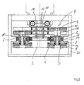
- FIG. 2 illustrates the structure of the grinding units 4 in a high section, which is in the conveying direction and is performed by two grinding units 4 therethrough.
- the grinding elements 8 of the grinding units each have a circular plate 16, in the center of an axis 17 attached.
- the plate 16 carries the downwardly projecting bristles 8 ', with which the grinding element 8 acts on the surface of a workpiece.
- the axis 17 extends through the housing base 5 by being rotatably supported by needle bearings 18. Above the housing base 5, the axis is provided with a spacer 19, 19 ', whose diameter is substantially larger than the diameter of the axis 17 within the housing base 5. With an upwardly projecting lug 20, the axis is rotatably connected to the driven pulley 9 in the form of a gear.
- the formed at its periphery with teeth gear 9 meshes with the circumferentially driven associated drive belt 10, two of which rotate at different heights.
- the axles with the longer spacer 19 have intermeshing gears 9 with the upper drive belt 10, while the gears 9 of the axles with the shorter spacer 19 'mesh with the bottom circulating drive belt.
- FIG. 2 can still be seen that the circumferential support rail 7 is fixedly mounted in a machine frame 21 and that the rollers 6 of the grinding units 4 are guided positively in the support rail 7.
- FIG. 2 shows further that the device feet 5 of the grinding units 8 are firmly connected to the links of the chain 1 and that the chain 1 is deflected by a deflection wheel 2. Above the guide wheel 2 are in FIG. 2 (non-driven) pulleys 22 for the drive belt 10 shown.
- FIG. 3 indicates that one of the pulleys 2 for the transport chain 1 is driven by an electric motor 23. Above the driven deflection roller 2 (not driven) deflection rollers 22 are also stored for the drive belt 10 here.
- FIG. 4 illustrates in an enlarged view in particular the drive roller assembly 13 through which the driving belt 15 is guided for the drive belt 10, wherein the drive belt 10 is formed on both sides serrated.
- FIG. 5 illustrates another embodiment for the drive of the grinding elements 8.
- the driven disc sits in the form of the gear 9 'not on the axis 17, but is connected via a drive belt connection 23 with the axis.
- the gear 9 ' is mounted on a pivot lever, which in the direction of in FIG. 5 drawn double arrow is pivotable. Under load of a spring (not shown), the pivot lever against the associated drive belt 10, which is also formed here double-toothed pressed.
- the arrangement with the spring-loaded pivot lever has the advantage that a safe and slip-free drive of the gear 9 'is ensured even if the drive belt 10 should be slightly longer in use and therefore could tend to inward, ie from the gear 9, 9 'away to give.
- the drive belt 10 is supported by a linear guide 25 along the rectilinear chain portions where the drive roller assembly 13 is not located. This linear guide 25 is also in the embodiment according to the FIGS. 1 to 4 contain.
Priority Applications (1)
| Application Number | Priority Date | Filing Date | Title |
|---|---|---|---|
| PL08011240T PL2011602T3 (pl) | 2007-07-06 | 2008-06-20 | Szlifierka |
Applications Claiming Priority (1)
| Application Number | Priority Date | Filing Date | Title |
|---|---|---|---|
| DE102007031656A DE102007031656A1 (de) | 2007-07-06 | 2007-07-06 | Schleifmaschine |
Publications (3)
| Publication Number | Publication Date |
|---|---|
| EP2011602A2 EP2011602A2 (de) | 2009-01-07 |
| EP2011602A3 EP2011602A3 (de) | 2010-01-27 |
| EP2011602B1 true EP2011602B1 (de) | 2010-10-27 |
Family
ID=39926517
Family Applications (1)
| Application Number | Title | Priority Date | Filing Date |
|---|---|---|---|
| EP08011240A Active EP2011602B1 (de) | 2007-07-06 | 2008-06-20 | Schleifmaschine |
Country Status (9)
| Country | Link |
|---|---|
| US (1) | US7632171B2 (zh) |
| EP (1) | EP2011602B1 (zh) |
| CN (1) | CN101434050B (zh) |
| AT (1) | ATE485918T1 (zh) |
| CA (1) | CA2636744C (zh) |
| DE (2) | DE102007031656A1 (zh) |
| ES (1) | ES2354003T3 (zh) |
| PL (1) | PL2011602T3 (zh) |
| PT (1) | PT2011602E (zh) |
Cited By (1)
| Publication number | Priority date | Publication date | Assignee | Title |
|---|---|---|---|---|
| DE102021105394A1 (de) | 2021-03-05 | 2022-09-08 | Karl Heesemann Maschinenfabrik Gmbh & Co. Kg | Aggregat zum Entgraten und Verrunden von Kanten in einer Flächenschleifmaschine |
Families Citing this family (15)
| Publication number | Priority date | Publication date | Assignee | Title |
|---|---|---|---|---|
| DK200701731A (da) * | 2007-12-04 | 2009-06-05 | Flex Trim As | Apparat til dobbeltsidet slibning |
| IT1396807B1 (it) * | 2009-11-25 | 2012-12-14 | Toncelli | Macchina di levigatura o lucidatura di lastre di materiale lapideo, quale pietra naturale e agglomerata, ceramico e vetro. |
| GB2491398B (en) * | 2011-06-03 | 2013-11-27 | Rolls Royce Plc | An apparatus and a method of shaping an edge of an aerofoil |
| JP5797145B2 (ja) * | 2012-03-29 | 2015-10-21 | 三菱重工業株式会社 | 研磨装置及びその方法 |
| MX366443B (es) * | 2013-02-05 | 2019-07-09 | Sintokogio Ltd | Una unidad de cepillo, un dispositivo para pulido con cepillo que utiliza la unidad de cepillo, un sistema para pulido con cepillo y un metodo para pulido con cepillo. |
| KR102110562B1 (ko) * | 2013-06-28 | 2020-05-14 | 삼성디스플레이 주식회사 | 기판 연마 장치 |
| KR20150002176A (ko) * | 2013-06-28 | 2015-01-07 | 삼성디스플레이 주식회사 | 기판 표면 연마 장치 |
| EP3172013B1 (en) * | 2014-07-24 | 2018-03-28 | Luca Toncelli | Method for smoothing and/or polishing slabs of stone or stone-like material |
| CN106181623A (zh) * | 2016-07-01 | 2016-12-07 | 芜湖中驰机床制造有限公司 | 一种回转型平面打磨机床 |
| CN106078499A (zh) * | 2016-08-11 | 2016-11-09 | 东莞市春草研磨科技有限公司 | 底旋转高震动的打磨装置 |
| CN108723959B (zh) * | 2018-03-29 | 2019-10-15 | 温州市强龙铜业有限公司 | 用于铜带生产线的刷箱机构 |
| CN108942606B (zh) * | 2018-06-05 | 2023-08-29 | 杭州同悦自动化设备有限公司 | 一种多轮清光装置 |
| CN108673327B (zh) * | 2018-06-05 | 2023-08-29 | 杭州同悦自动化设备有限公司 | 一种高效清光机 |
| CN111496641A (zh) * | 2020-04-03 | 2020-08-07 | 大连富地重工机械制造有限公司 | 一种连续棒料磨削装置 |
| CN113696091B (zh) * | 2021-10-27 | 2022-02-08 | 江苏华兴激光科技有限公司 | 一种外延片的快速研磨方法及装置 |
Family Cites Families (9)
| Publication number | Priority date | Publication date | Assignee | Title |
|---|---|---|---|---|
| US1732695A (en) * | 1926-08-16 | 1929-10-22 | Edward Ford Plate Glass Compan | Glass-polishing apparatus |
| US1666347A (en) * | 1926-09-03 | 1928-04-17 | Edward Ford Plate Glass Compan | Continuous glass-polishing means |
| US2985989A (en) * | 1958-07-15 | 1961-05-30 | Lloyd H Knost | Slab surfacing machine |
| US2948087A (en) * | 1958-11-03 | 1960-08-09 | Reproduction Res Lab Inc | Plate graining apparatus |
| US6113472A (en) * | 1997-02-28 | 2000-09-05 | Rosa; Valerio | Method and an apparatus for polishing a roller and for removing the chromium plating thereof |
| DE10035977A1 (de) * | 2000-07-24 | 2002-02-07 | Buetfering Maschinenfabrik Gmb | Verfahren und Vorrichtung zur Bearbeitung von Werkstück-Oberflächen |
| DK200301826A (da) * | 2003-12-10 | 2005-06-11 | Flex Trim As | Slibeapparat til behandling af en flade |
| DE20319366U1 (de) | 2003-12-13 | 2004-03-11 | Jakob Löwer Inh. von Schumann GmbH & Co. KG | Durchlaufschleifmaschine zum Bearbeiten einer ebenen Werkstückoberfläche |
| CN2789249Y (zh) * | 2005-05-20 | 2006-06-21 | 中山市富山玻璃机械有限公司 | 一种平面玻璃用多排盘刷清洗、抛光机 |
-
2007
- 2007-07-06 DE DE102007031656A patent/DE102007031656A1/de not_active Withdrawn
-
2008
- 2008-06-20 DE DE502008001623T patent/DE502008001623D1/de active Active
- 2008-06-20 AT AT08011240T patent/ATE485918T1/de active
- 2008-06-20 ES ES08011240T patent/ES2354003T3/es active Active
- 2008-06-20 EP EP08011240A patent/EP2011602B1/de active Active
- 2008-06-20 PL PL08011240T patent/PL2011602T3/pl unknown
- 2008-06-20 PT PT08011240T patent/PT2011602E/pt unknown
- 2008-07-01 US US12/165,927 patent/US7632171B2/en active Active
- 2008-07-03 CA CA2636744A patent/CA2636744C/en active Active
- 2008-07-04 CN CN2008101737857A patent/CN101434050B/zh active Active
Cited By (2)
| Publication number | Priority date | Publication date | Assignee | Title |
|---|---|---|---|---|
| DE102021105394A1 (de) | 2021-03-05 | 2022-09-08 | Karl Heesemann Maschinenfabrik Gmbh & Co. Kg | Aggregat zum Entgraten und Verrunden von Kanten in einer Flächenschleifmaschine |
| WO2022184882A2 (de) | 2021-03-05 | 2022-09-09 | Karl Heesemann Maschinenfabrik Gmbh & Co. Kg | Aggregat zum entgraten und verrunden von kanten in einer flächenschleifmaschine |
Also Published As
| Publication number | Publication date |
|---|---|
| EP2011602A3 (de) | 2010-01-27 |
| DE502008001623D1 (de) | 2010-12-09 |
| DE102007031656A1 (de) | 2009-01-08 |
| PT2011602E (pt) | 2010-12-21 |
| CA2636744A1 (en) | 2009-01-06 |
| CA2636744C (en) | 2012-04-24 |
| EP2011602A2 (de) | 2009-01-07 |
| ES2354003T3 (es) | 2011-03-09 |
| PL2011602T3 (pl) | 2011-04-29 |
| ATE485918T1 (de) | 2010-11-15 |
| CN101434050A (zh) | 2009-05-20 |
| US7632171B2 (en) | 2009-12-15 |
| CN101434050B (zh) | 2011-12-21 |
| US20090011689A1 (en) | 2009-01-08 |
Similar Documents
| Publication | Publication Date | Title |
|---|---|---|
| EP2011602B1 (de) | Schleifmaschine | |
| EP2593384B1 (de) | Transfer-fördervorrichtung | |
| DE2856519C2 (de) | Maschine zum Schleifen der Ränder von Glasplatten | |
| DE3004389C2 (de) | Fördereinrichtung an einer Kantenbearbeitungsmaschine für plattenförmige Werkstücke | |
| EP3398754B1 (de) | Antriebsanordnung für schweissautomaten | |
| DE102012104213B4 (de) | Transportsystem für Behandlungsmaschinen sowie Behandlungsmaschine | |
| EP1175961A2 (de) | Verfahren und Vorrichtung zur Bearbeitung von Werkstück-Oberflächen | |
| DE20319366U1 (de) | Durchlaufschleifmaschine zum Bearbeiten einer ebenen Werkstückoberfläche | |
| DE102011018942B4 (de) | Transportstrecke für Behandlungsmaschinen sowie Behandlungsmaschine | |
| EP1510477A1 (de) | Reibrollentrieb für auf Tragrollen verfahrbare Skids | |
| DE60304179T2 (de) | Schleifmaschine | |
| EP0799580B1 (de) | Schälmaschine | |
| DE3523901A1 (de) | Glasplattenschleifmaschine | |
| EP1699717B1 (de) | Einheit für behälter-rücknahmeautomaten | |
| DE10158646A1 (de) | Vorrichtung zum Besäumen von Glastafeln | |
| EP1632444B1 (de) | Vorrichtung zum getakteten Transport von Werkstückträgern | |
| DE202009004734U1 (de) | Kurvenrollenbahn | |
| DE3224330A1 (de) | Vorrichtung zum transport von wenigstens einem werkstuecktraeger, insbesondere zur verkettung von maschinen oder arbeitsstationen | |
| EP1319447B1 (de) | Reinigungseinrichtung insbesondere für Backbleche | |
| DE4028181A1 (de) | Duplex-foerderer | |
| DE3109427C2 (zh) | ||
| DE3734175C2 (de) | Mehrzweck-Werkzeugmaschine | |
| DE1814933A1 (de) | Umlaufstapler | |
| DE615677C (de) | Tabakschneidvorrichtung mit zwei umlaufenden Messerwalzen | |
| EP0060501B1 (de) | Bogenbearbeitungsmaschine |
Legal Events
| Date | Code | Title | Description |
|---|---|---|---|
| PUAI | Public reference made under article 153(3) epc to a published international application that has entered the european phase |
Free format text: ORIGINAL CODE: 0009012 |
|
| AK | Designated contracting states |
Kind code of ref document: A2 Designated state(s): AT BE BG CH CY CZ DE DK EE ES FI FR GB GR HR HU IE IS IT LI LT LU LV MC MT NL NO PL PT RO SE SI SK TR |
|
| AX | Request for extension of the european patent |
Extension state: AL BA MK RS |
|
| PUAL | Search report despatched |
Free format text: ORIGINAL CODE: 0009013 |
|
| AK | Designated contracting states |
Kind code of ref document: A3 Designated state(s): AT BE BG CH CY CZ DE DK EE ES FI FR GB GR HR HU IE IS IT LI LT LU LV MC MT NL NO PL PT RO SE SI SK TR |
|
| AX | Request for extension of the european patent |
Extension state: AL BA MK RS |
|
| 17P | Request for examination filed |
Effective date: 20100217 |
|
| GRAP | Despatch of communication of intention to grant a patent |
Free format text: ORIGINAL CODE: EPIDOSNIGR1 |
|
| GRAS | Grant fee paid |
Free format text: ORIGINAL CODE: EPIDOSNIGR3 |
|
| GRAA | (expected) grant |
Free format text: ORIGINAL CODE: 0009210 |
|
| AKX | Designation fees paid |
Designated state(s): AT BE BG CH CY CZ DE DK EE ES FI FR GB GR HR HU IE IS IT LI LT LU LV MC MT NL NO PL PT RO SE SI SK TR |
|
| AK | Designated contracting states |
Kind code of ref document: B1 Designated state(s): AT BE BG CH CY CZ DE DK EE ES FI FR GB GR HR HU IE IS IT LI LT LU LV MC MT NL NO PL PT RO SE SI SK TR |
|
| REG | Reference to a national code |
Ref country code: GB Ref legal event code: FG4D Free format text: NOT ENGLISH |
|
| REG | Reference to a national code |
Ref country code: CH Ref legal event code: EP |
|
| REG | Reference to a national code |
Ref country code: IE Ref legal event code: FG4D Free format text: LANGUAGE OF EP DOCUMENT: GERMAN |
|
| REF | Corresponds to: |
Ref document number: 502008001623 Country of ref document: DE Date of ref document: 20101209 Kind code of ref document: P |
|
| REG | Reference to a national code |
Ref country code: PT Ref legal event code: SC4A Free format text: AVAILABILITY OF NATIONAL TRANSLATION Effective date: 20101214 |
|
| REG | Reference to a national code |
Ref country code: SE Ref legal event code: TRGR |
|
| REG | Reference to a national code |
Ref country code: NL Ref legal event code: VDEP Effective date: 20101027 |
|
| REG | Reference to a national code |
Ref country code: ES Ref legal event code: FG2A Effective date: 20110225 |
|
| LTIE | Lt: invalidation of european patent or patent extension |
Effective date: 20101027 |
|
| PG25 | Lapsed in a contracting state [announced via postgrant information from national office to epo] |
Ref country code: LT Free format text: LAPSE BECAUSE OF FAILURE TO SUBMIT A TRANSLATION OF THE DESCRIPTION OR TO PAY THE FEE WITHIN THE PRESCRIBED TIME-LIMIT Effective date: 20101027 Ref country code: NO Free format text: LAPSE BECAUSE OF FAILURE TO SUBMIT A TRANSLATION OF THE DESCRIPTION OR TO PAY THE FEE WITHIN THE PRESCRIBED TIME-LIMIT Effective date: 20110127 |
|
| REG | Reference to a national code |
Ref country code: PL Ref legal event code: T3 |
|
| REG | Reference to a national code |
Ref country code: IE Ref legal event code: FD4D |
|
| PG25 | Lapsed in a contracting state [announced via postgrant information from national office to epo] |
Ref country code: NL Free format text: LAPSE BECAUSE OF FAILURE TO SUBMIT A TRANSLATION OF THE DESCRIPTION OR TO PAY THE FEE WITHIN THE PRESCRIBED TIME-LIMIT Effective date: 20101027 Ref country code: FI Free format text: LAPSE BECAUSE OF FAILURE TO SUBMIT A TRANSLATION OF THE DESCRIPTION OR TO PAY THE FEE WITHIN THE PRESCRIBED TIME-LIMIT Effective date: 20101027 Ref country code: HR Free format text: LAPSE BECAUSE OF FAILURE TO SUBMIT A TRANSLATION OF THE DESCRIPTION OR TO PAY THE FEE WITHIN THE PRESCRIBED TIME-LIMIT Effective date: 20101027 Ref country code: BG Free format text: LAPSE BECAUSE OF FAILURE TO SUBMIT A TRANSLATION OF THE DESCRIPTION OR TO PAY THE FEE WITHIN THE PRESCRIBED TIME-LIMIT Effective date: 20110127 Ref country code: IS Free format text: LAPSE BECAUSE OF FAILURE TO SUBMIT A TRANSLATION OF THE DESCRIPTION OR TO PAY THE FEE WITHIN THE PRESCRIBED TIME-LIMIT Effective date: 20110227 Ref country code: LV Free format text: LAPSE BECAUSE OF FAILURE TO SUBMIT A TRANSLATION OF THE DESCRIPTION OR TO PAY THE FEE WITHIN THE PRESCRIBED TIME-LIMIT Effective date: 20101027 Ref country code: SI Free format text: LAPSE BECAUSE OF FAILURE TO SUBMIT A TRANSLATION OF THE DESCRIPTION OR TO PAY THE FEE WITHIN THE PRESCRIBED TIME-LIMIT Effective date: 20101027 |
|
| PG25 | Lapsed in a contracting state [announced via postgrant information from national office to epo] |
Ref country code: GR Free format text: LAPSE BECAUSE OF FAILURE TO SUBMIT A TRANSLATION OF THE DESCRIPTION OR TO PAY THE FEE WITHIN THE PRESCRIBED TIME-LIMIT Effective date: 20110128 |
|
| PG25 | Lapsed in a contracting state [announced via postgrant information from national office to epo] |
Ref country code: EE Free format text: LAPSE BECAUSE OF FAILURE TO SUBMIT A TRANSLATION OF THE DESCRIPTION OR TO PAY THE FEE WITHIN THE PRESCRIBED TIME-LIMIT Effective date: 20101027 Ref country code: IE Free format text: LAPSE BECAUSE OF FAILURE TO SUBMIT A TRANSLATION OF THE DESCRIPTION OR TO PAY THE FEE WITHIN THE PRESCRIBED TIME-LIMIT Effective date: 20101027 Ref country code: CZ Free format text: LAPSE BECAUSE OF FAILURE TO SUBMIT A TRANSLATION OF THE DESCRIPTION OR TO PAY THE FEE WITHIN THE PRESCRIBED TIME-LIMIT Effective date: 20101027 |
|
| PG25 | Lapsed in a contracting state [announced via postgrant information from national office to epo] |
Ref country code: RO Free format text: LAPSE BECAUSE OF FAILURE TO SUBMIT A TRANSLATION OF THE DESCRIPTION OR TO PAY THE FEE WITHIN THE PRESCRIBED TIME-LIMIT Effective date: 20101027 Ref country code: SK Free format text: LAPSE BECAUSE OF FAILURE TO SUBMIT A TRANSLATION OF THE DESCRIPTION OR TO PAY THE FEE WITHIN THE PRESCRIBED TIME-LIMIT Effective date: 20101027 Ref country code: DK Free format text: LAPSE BECAUSE OF FAILURE TO SUBMIT A TRANSLATION OF THE DESCRIPTION OR TO PAY THE FEE WITHIN THE PRESCRIBED TIME-LIMIT Effective date: 20101027 |
|
| PLBE | No opposition filed within time limit |
Free format text: ORIGINAL CODE: 0009261 |
|
| STAA | Information on the status of an ep patent application or granted ep patent |
Free format text: STATUS: NO OPPOSITION FILED WITHIN TIME LIMIT |
|
| 26N | No opposition filed |
Effective date: 20110728 |
|
| REG | Reference to a national code |
Ref country code: DE Ref legal event code: R097 Ref document number: 502008001623 Country of ref document: DE Effective date: 20110728 |
|
| PG25 | Lapsed in a contracting state [announced via postgrant information from national office to epo] |
Ref country code: MT Free format text: LAPSE BECAUSE OF FAILURE TO SUBMIT A TRANSLATION OF THE DESCRIPTION OR TO PAY THE FEE WITHIN THE PRESCRIBED TIME-LIMIT Effective date: 20101027 |
|
| BERE | Be: lapsed |
Owner name: HEESEMANN, JURGEN Effective date: 20110630 |
|
| PG25 | Lapsed in a contracting state [announced via postgrant information from national office to epo] |
Ref country code: BE Free format text: LAPSE BECAUSE OF NON-PAYMENT OF DUE FEES Effective date: 20110630 |
|
| REG | Reference to a national code |
Ref country code: CH Ref legal event code: PL |
|
| REG | Reference to a national code |
Ref country code: CH Ref legal event code: PL |
|
| GBPC | Gb: european patent ceased through non-payment of renewal fee |
Effective date: 20120620 |
|
| PG25 | Lapsed in a contracting state [announced via postgrant information from national office to epo] |
Ref country code: LI Free format text: LAPSE BECAUSE OF NON-PAYMENT OF DUE FEES Effective date: 20120630 Ref country code: GB Free format text: LAPSE BECAUSE OF NON-PAYMENT OF DUE FEES Effective date: 20120620 Ref country code: CH Free format text: LAPSE BECAUSE OF NON-PAYMENT OF DUE FEES Effective date: 20120630 Ref country code: MC Free format text: LAPSE BECAUSE OF NON-PAYMENT OF DUE FEES Effective date: 20110630 |
|
| PG25 | Lapsed in a contracting state [announced via postgrant information from national office to epo] |
Ref country code: LU Free format text: LAPSE BECAUSE OF NON-PAYMENT OF DUE FEES Effective date: 20110620 Ref country code: CY Free format text: LAPSE BECAUSE OF FAILURE TO SUBMIT A TRANSLATION OF THE DESCRIPTION OR TO PAY THE FEE WITHIN THE PRESCRIBED TIME-LIMIT Effective date: 20101027 |
|
| PG25 | Lapsed in a contracting state [announced via postgrant information from national office to epo] |
Ref country code: TR Free format text: LAPSE BECAUSE OF FAILURE TO SUBMIT A TRANSLATION OF THE DESCRIPTION OR TO PAY THE FEE WITHIN THE PRESCRIBED TIME-LIMIT Effective date: 20101027 |
|
| REG | Reference to a national code |
Ref country code: DE Ref legal event code: R082 Ref document number: 502008001623 Country of ref document: DE Representative=s name: GRAMM, LINS & PARTNER GBR, DE |
|
| PG25 | Lapsed in a contracting state [announced via postgrant information from national office to epo] |
Ref country code: HU Free format text: LAPSE BECAUSE OF FAILURE TO SUBMIT A TRANSLATION OF THE DESCRIPTION OR TO PAY THE FEE WITHIN THE PRESCRIBED TIME-LIMIT Effective date: 20101027 |
|
| REG | Reference to a national code |
Ref country code: DE Ref legal event code: R082 Ref document number: 502008001623 Country of ref document: DE Representative=s name: GRAMM, LINS & PARTNER GBR, DE Effective date: 20131001 Ref country code: DE Ref legal event code: R081 Ref document number: 502008001623 Country of ref document: DE Owner name: KARL HEESEMANN MASCHINENFABRIK GMBH & CO KG, DE Free format text: FORMER OWNER: HEESEMANN, JUERGEN, 32547 BAD OEYNHAUSEN, DE Effective date: 20131001 Ref country code: DE Ref legal event code: R082 Ref document number: 502008001623 Country of ref document: DE Representative=s name: GRAMM, LINS & PARTNER PATENT- UND RECHTSANWAEL, DE Effective date: 20131001 Ref country code: DE Ref legal event code: R081 Ref document number: 502008001623 Country of ref document: DE Owner name: KARL HEESEMANN MASCHINENFABRIK GMBH & CO. KG, DE Free format text: FORMER OWNER: HEESEMANN, JUERGEN, 32547 BAD OEYNHAUSEN, DE Effective date: 20131001 |
|
| REG | Reference to a national code |
Ref country code: DE Ref legal event code: R082 Ref document number: 502008001623 Country of ref document: DE Representative=s name: GRAMM, LINS & PARTNER PATENT- UND RECHTSANWAEL, DE |
|
| REG | Reference to a national code |
Ref country code: FR Ref legal event code: PLFP Year of fee payment: 9 |
|
| REG | Reference to a national code |
Ref country code: FR Ref legal event code: PLFP Year of fee payment: 10 |
|
| REG | Reference to a national code |
Ref country code: FR Ref legal event code: PLFP Year of fee payment: 11 |
|
| REG | Reference to a national code |
Ref country code: DE Ref legal event code: R082 Ref document number: 502008001623 Country of ref document: DE Representative=s name: EISENFUEHR SPEISER PATENTANWAELTE RECHTSANWAEL, DE |
|
| PGFP | Annual fee paid to national office [announced via postgrant information from national office to epo] |
Ref country code: IT Payment date: 20230626 Year of fee payment: 16 Ref country code: DE Payment date: 20230623 Year of fee payment: 16 |
|
| PGFP | Annual fee paid to national office [announced via postgrant information from national office to epo] |
Ref country code: SE Payment date: 20230629 Year of fee payment: 16 Ref country code: PL Payment date: 20210804 Year of fee payment: 15 Ref country code: AT Payment date: 20230623 Year of fee payment: 16 |
|
| PGFP | Annual fee paid to national office [announced via postgrant information from national office to epo] |
Ref country code: ES Payment date: 20230706 Year of fee payment: 16 |
|
| PGFP | Annual fee paid to national office [announced via postgrant information from national office to epo] |
Ref country code: PT Payment date: 20230705 Year of fee payment: 16 Ref country code: FR Payment date: 20230705 Year of fee payment: 16 |
|
| PGFP | Annual fee paid to national office [announced via postgrant information from national office to epo] |
Ref country code: PL Payment date: 20231106 Year of fee payment: 16 |