EP2011128B1 - Verfahren zur dimensionierung einer abtrennvorrichtung für überspannungsableiter - Google Patents
Verfahren zur dimensionierung einer abtrennvorrichtung für überspannungsableiter Download PDFInfo
- Publication number
- EP2011128B1 EP2011128B1 EP07727670.7A EP07727670A EP2011128B1 EP 2011128 B1 EP2011128 B1 EP 2011128B1 EP 07727670 A EP07727670 A EP 07727670A EP 2011128 B1 EP2011128 B1 EP 2011128B1
- Authority
- EP
- European Patent Office
- Prior art keywords
- switching
- force
- tongue
- movement
- point
- Prior art date
- Legal status (The legal status is an assumption and is not a legal conclusion. Google has not performed a legal analysis and makes no representation as to the accuracy of the status listed.)
- Active
Links
Images


Classifications
-
- H—ELECTRICITY
- H01—ELECTRIC ELEMENTS
- H01H—ELECTRIC SWITCHES; RELAYS; SELECTORS; EMERGENCY PROTECTIVE DEVICES
- H01H37/00—Thermally-actuated switches
- H01H37/74—Switches in which only the opening movement or only the closing movement of a contact is effected by heating or cooling
- H01H37/76—Contact member actuated by melting of fusible material, actuated due to burning of combustible material or due to explosion of explosive material
- H01H37/761—Contact member actuated by melting of fusible material, actuated due to burning of combustible material or due to explosion of explosive material with a fusible element forming part of the switched circuit
-
- H—ELECTRICITY
- H01—ELECTRIC ELEMENTS
- H01C—RESISTORS
- H01C7/00—Non-adjustable resistors formed as one or more layers or coatings; Non-adjustable resistors made from powdered conducting material or powdered semi-conducting material with or without insulating material
- H01C7/10—Non-adjustable resistors formed as one or more layers or coatings; Non-adjustable resistors made from powdered conducting material or powdered semi-conducting material with or without insulating material voltage responsive, i.e. varistors
- H01C7/12—Overvoltage protection resistors; Arresters
- H01C7/126—Means for protecting against excessive pressure or for disconnecting in case of failure
-
- H—ELECTRICITY
- H01—ELECTRIC ELEMENTS
- H01H—ELECTRIC SWITCHES; RELAYS; SELECTORS; EMERGENCY PROTECTIVE DEVICES
- H01H37/00—Thermally-actuated switches
- H01H37/74—Switches in which only the opening movement or only the closing movement of a contact is effected by heating or cooling
- H01H37/76—Contact member actuated by melting of fusible material, actuated due to burning of combustible material or due to explosion of explosive material
- H01H37/761—Contact member actuated by melting of fusible material, actuated due to burning of combustible material or due to explosion of explosive material with a fusible element forming part of the switched circuit
- H01H2037/762—Contact member actuated by melting of fusible material, actuated due to burning of combustible material or due to explosion of explosive material with a fusible element forming part of the switched circuit using a spring for opening the circuit when the fusible element melts
- H01H2037/763—Contact member actuated by melting of fusible material, actuated due to burning of combustible material or due to explosion of explosive material with a fusible element forming part of the switched circuit using a spring for opening the circuit when the fusible element melts the spring being a blade spring
Definitions
- the invention relates to a disconnecting device for a surge arrester whose switching movement is performed by a switching tongue, according to claim 1.
- the solder Under the influence of a heating, whose heat source preferably forms a surge protection component to be monitored, the solder is liquefied and separated as a result of thereby triggered switching movement of a specially designed part of the separation device, an electrical connection.
- the part of the separating device, which performs the switching movement is, for example after DE 295 19 313 U1 biased by a spring force oriented in the switching direction. The switching movement reaches its absolute end point as soon as the preload force of this spring is used up.
- Disconnecting devices according to the prior art are known as a disadvantage that the biasing force, if it acts permanently on the Lotstelle, already without thermal influence can cause a purely mechanical, unintentional triggering.
- a certain biasing force is necessary to achieve a correspondingly effective switching movement, i. that a sufficient switching path (separation distance) and a sufficient switching speed can be achieved.
- Both the switching path and the switching speed are parameters that determine the performance (switching capacity) of the separating device. Since with increasing switching path, a purely mechanical biasing force decreases rapidly, it is very difficult to ensure on the one hand over the entire switching path sufficient switching speed and on the other hand to limit the biasing force on the Lotstelle to a value that excludes with sufficient certainty a purely mechanically induced false triggering. In practice, therefore, a compromise is required, which allows a sufficient biasing force depending on the execution of the Lotstelle, the Lotmenge and finally also the composition of the solder. This requires a stable manufacturing process, especially with regard to must be redefined on the introduction of lead-free solders and usually requires a further reduction of the preload force.
- the biasing force should be able to be increased to the extent that on the one hand, an improved switching power on the switching path and the switching speed results, on the other hand, however, the risk of a purely mechanical triggering caused thereby does not exist.
- the forces F1 / F2 and F3 can be generated as independently organized individual forces from one or more of the same or different energy stores.
- the total prestressing force which acts on the soldering point is composed of at least two partial forces whose force effects (Effective directions) reinforce in the direction of switching movement as needed complementary.
- first biasing force F1 which acts permanently on the Lotstelle, also act one or more other forces demand-oriented by e.g. At normal soldering temperature are almost ineffective and only with increasing soldering temperature or during the separation or switching process bring their force effect.
- This force influence or distribution developed according to demand can be used as a function of state or temperature continuously or abruptly starting from a certain state of the switch position and / or a certain temperature.
- the invention is based on an increased force acting on the separating element during the entire separation process, i. during the Ausloöt- and the subsequent switching phase, which is influenced or supported by additional thermal and / or mechanical effects. This is e.g. then the case when a switching tongue used as a separating element itself supports the thermal force action or this force is even formed out of itself, e.g. is made of a material having the required mechanical / thermal properties.
- the switching tongue is formed from a molded part, at the first aus convinceddem end a contact clip for external contact with a male part and at the second expiring end of a specially trained or formable Lotspitze is formed.
- This Lotspitze is connected via a defined Lotstelle with the active, serving in case of failure as a heat source part of the arrester and thus forms an electrical / thermal connection using the described Preload force F1 is extinguished at the corresponding temperature influence, executes a switching movement. Due to the switching movement, the circuit is permanently interrupted by the now faulty arrester.
- a second biasing force F2 is required intervention in the separation process.
- this can be effected thermally, e.g. Already while the soldering point is "heated up” is increasing steadily or suddenly and so supports the Auslötvorgang.
- the separation process starting after the brazing operation can be assisted by the biasing force F2 by acting so that the separation process undergoes an additional "acceleration", e.g. the switching path is increased by a further opening of the separation path by deformation of the switching tongue.
- the electrical separation is improved, which is particularly advantageous at higher system voltages.
- the predominantly thermally induced prestressing force acting together with the first pretensioning force F1 is referred to as F2 and the preloading force acting predominantly mechanically together with F1 after the soldering operation is referred to as the shifting force F3.
- the switching tongue consists of a metallic, electrically conductive material which is deformable under the influence of heat.
- Such metals according to the prior art, have two different stable states of formation which are temperature-dependent.
- the second stable state which sets in under the influence of heat, on the other hand corresponds to the opened state of the separating device, so that with increasing heating, the bias voltage increases (steadily or abruptly) and thus increases the mechanical prestressing on the soldering point.
- a demand-based bias is generated, which ultimately also leads to high switching speeds, even with large switching paths.
- bi-metals are suitable for providing such a function.
- the memory metals consist of a metal alloy (eg nickel / titanium).
- the bimetals where the tendency to go into the second stable state increases steadily with increasing temperature, the memory metals have a certain temperature point at which they move abruptly in the manner of a switching movement from one state to the other and there remain when the temperature that led to the tripping has fallen off again.
- the embodiment of a switching tongue is conceivable, which generates in addition to the mentioned thermal effect of a biasing force F2 and the first, mechanically induced biasing force F1 by all or part of a combination of one of the mentioned thermal materials with a resilient material.
- both a specific area and the entire switching tongue in sandwich construction can be equipped with the thermally reacting metal.
- a mechanical tension or compression spring for generating the biasing force F1 is possibly replaced by the resilient effect of the reed tongue material.
- the achievable effect of such a combination is the same as in the embodiment according to the first variant with the functionally separate elements for generating the force effect F1 / F2.
- An advantage may arise in certain applications arise, for example, where there is a risk that the mechanical suspension of the spring for the biasing force F1 triggers (eg by mechanical shocks) or space requirements require a compact design of the separation device according to the invention.
- the biasing force F1 decreases steadily during the switching movement with increasing switching path.
- This effect can be compensated only partially by the biasing force F2, since this partial force unfolds only in the Auslötphase and after the heat supply is interrupted by the separation process, this force decreases more or less steadily.
- a further force F3 is provided according to the invention, which unfolds during the switching operation and thus at least partially compensates for the decreasing effect of F1 or F2 .
- the provision of this additional force takes place exclusively during the switching process and unfolds in the same direction relative to the pretensioning forces F1 / F2, but inversely offset in time. It is derived from the movement of the switching tongue by the force ratio is influenced by changing force and or leverage effects by a constant displacement of a power transmission point along the switching tongue so that the resulting force F3 increases steadily with increasing switching path.
- the invention provides a separation device for surge arresters with extended functional scope, which is that a first biasing force F1 is supported according to the prior art by at least one second biasing force F2 or switching force F3 according to the invention as needed to the triggering and switching characteristic to improve, on the one hand reduces the force on the Lotstelle at normal ambient temperature and on the other hand, the Abtrennweg or the separation speed compared to the prior art is increased.
- the separating means of the separating device according to the invention are located together with the over-voltage protection element to be monitored preferably in the attachable upper part of a two-part housing, but are in principle also a one-piece arrangement can be realized.
- the upper part has means for contacting with a lower part and a display window on which the switching state of the separating device is optically displayed.
- the lower part contacted via corresponding mating contacts the upper part and also has connection means for the outer terminals.
- the active element represents a surge-limiting or a overvoltage-switching component which is monitored by the separating device for exceeding a specific heating temperature.
- Exceeding given temperature values is considered to be the defective state of the active device (e.g., spark gap and / or varistor), requiring its disconnection from the power supply via the disconnect device.
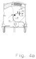
- FIG. 1a shows the upper part of a basic embodiment of a pluggable surge arrester, on which the invention essentially builds.
- both contact pieces (4, 6) consist of a single piece as a stamped, drawn or stamped part of a preferably thermally deformable and / or resilient and yet highly conductive material, at whose end or expression respectively contact springs (4b , 6b) or contact bracket (6a) for contacting the lower part or the arrester element (5) are integrally formed.
- a first of the two contact pieces (4) is formed in its design or configuration as a switching tongue (4c) of a separating device with extended properties, wherein an embodiment of the switching tongue (4c) as a rail once without expression and in another embodiment with a is formed centrally arranged expression. It is essential that both versions of the contact pieces (4) consist of a single part. At its end is the solder pad (4d) whose solder connection (4f) melts at a concomitant with heating overload of the arrester element (5) on the contact (5a) by heat transfer and with a switching movement of the switching tongue (4c) causes the intended shutdown ,
- the switching movement of the switching tongue (4c) results from a spring tension, which exerts indirectly via a separating block (2) a bias on the switching tongue (4c) and thus on the solder pad (4d).
- This bias corresponds to the biasing force F1.
- the separated switching tongue (4c) performs a correspondingly fast switching movement over a large opening path and thus provides a safe separation between the arrester element (5) and the cable formed by the switching tongue (4c) ago.
- the rotary movement performed by the separating block (2) is displayed in its end position (1b) in a viewing window (1a), so that the switching position of the separating block (2) can be recognized as a triggering state on the basis of its scarf surface (2d).
- the spring preload F1 for the switching tongue (4c) is generated by a spring (3) having its fixed point at the end of a housing groove (4a).
- the pressure force thus generated by the spring acts on the separating block (2) at point (2c), which in turn acts on the pivot bearing (2a) of the separating block and thus enables the already mentioned rotational movement.
- the spring preload F1 acts on the disconnect block (2) on the switching tongue (4c) and thus on the solder pad (4d). Further support can be obtained by the fact that the switching tongue (4c) itself generates a bias, which may consist of a spring clip or of a bimetal or memory metal strip.
- thermoformable metals that are designed to accept (at least) two stable, temperature dependent positions or shapes may be used to assist in the brazing operation.
- This effect is used in the invention so that the switching tongue with increasing temperature an increasing tensile force F2 in the switching direction learns and thus in addition to the spring force F1 increases the bias, which positively influences the initiated Auslöt- and the subsequent separation or switching operation.
- the bias of the tab generated by the combination F1 / F2 not only has an amplifying effect on the brazing operation, but additionally increases the reliability of the initiation of a switching operation by two independently acting, rectified forces.
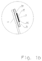
- the Lotstelle that connects the tongue with the arrester element is designed and manufactured so that the separation takes place safely and at a time when no thermal damage can be foreseen by a superheated discharge element. This point is first determined by the choice of the solder, with the described mechanical bias provides a significant share to it. Furthermore, the Lotmenge at the Lotstelle (4f) (see FIG. 1b ) and the heat distribution at the solder pad be optimized.
- solder pad (4d) is formed so that it receives only a limited amount of solder by the end of the switching tongue (4c) as a contact blade (4d '), which dips as a mating contact in a slot-shaped aperture (5c) and with its protruding Part is soldered to the contact (5a) of the active element (5) is formed.
- highly heat-conductive metals or metal alloys or coatings are preferably used at least or exclusively in the area of the solder contact point (4d).
- the second contact piece (6) is formed so that it exerts via corresponding supports in the GeHouserenzteil which is designed for receiving the components, a contact pressure on the bracket (6 a) on the contact surface (5 b) of the arrester element (5) is soldered with this contact piece.
- the supports consist of braided webs, which at the same time increase the strength of the housing half part (1), so that a continuous contact pressure is also ensured by a corresponding rigidity of the carrier housing.
- both contact pieces (4, 6) are guided and held in position.
- the webs act as insulation for the contact pieces in certain areas or support or reinforce their shape there and thus make it possible for the contact pieces, for example can be mechanically loaded in the region of the plug contacts, without thereby deform.
- the generation of the switching force F3 according to the invention is based on FIGS. 2 to 4 explained. It unfolds its effect as soon as the Auslötvorgang is completed and moves the tongue in the direction of the end position for the open state. So it acts as the biasing force F2 demand-oriented but time-displaced together with F1.
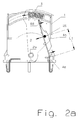
- FIGS. 2a and 2 B show a first example of the invention respectively in the closed and in the triggered state.
- the invention essential feature of this embodiment are two differently arranged pivot points, of which a first at the point (4e) of the switching tongue and a second at the point (2a) is associated with the Abtrennbock.
- the force effect of F1 biases the switching tongue in the direction of the switching movement via a fixed point (2b) on the disconnecting block in the untripped state.
- the separation is initiated under the action of the force F1 on the fixed point (2b) on the switching tongue, wherein the force of the fixed point on the Switching tongue exerts with increasing switching path in the direction of separation contact (4d) moves.
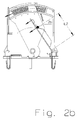
- FIGS. 3a and 3b show a second example of the invention in each case in the closed and in the triggered state.
- the triggering process up to the in FIG. 3b shown position of the tongue is so far identical to the one in FIG. 2a / 2 B already described.
- this variant of the invention has an additional function that, starting from this position of the switching position, which already represents the end position of the rotary movement through the Abtrennbock causes a further extension of the switching path.
- This switch position is in Figure 3c shown.
- the switching tongue (4c) used for this ( Figure 3d / 3e ) is formed from a spring material having in a certain area an expression with an arcuate web (4h).
- the over-arched bridge acts as an integrated spring clip. Due to the mechanical preload that the tongue learns by the overbending of the web or the spring clip acts in the soldered state, first a biasing force (F2 ') in the direction of Lotstelle, whereby the bias voltage is reduced in the switching direction by the spring force F1. After the Auslötvorgang is completed, the switching tongue sets under the predominant influence of F1 in the usual way from the Lotstelle by a switching movement in the direction of the end position.
- the overbend (4h) thereby undergoes an overstretching, so that it abruptly tilts in the opposite direction S2 ', whereby the switching tongue altogether performs a tilting movement by deformation of the web towards the end position and thus additionally increases the switching path beyond the actual end position of the switching movement S1 by the amount S2 ( Figure 3c ).
- FIGS. 4a / 4b show a third variant of the invention respectively in the soldered and in the soldered state.
- This variant has an approximately S-shaped pre-bent switching tongue (4c), as in FIG. 4b can be seen in the soldered state.
- the front portion of the tab In the closed state after FIG. 4a the front portion of the tab is bent into a U-shape, the open end (4d ') of which projects into a slot (5c) of the solder tab (5a) and is soldered therein.
- the fixed point (2b) of the Abtrennbocks transmits the biasing force F1 of the spring on the switching tongue and changed during the deletion following separation movement his point of attack so that it supports the separation movement.
- FIG. 5a shows by way of example the interaction of the individual partial forces F1, F2 and F3 during a Auslötvorganges by heating T of the Ableiteriatas to be monitored with subsequent separation of the switching tongue and the switching path, the switching tongue travels to the end stop.
- the Auslötvorgang is in the range A.
- the heating temperature T of the arrester increases starting at the ambient temperature T u until the Auslöttemperatur T A is reached.
- the arrester cools off again over time.
- overheating of the entire system which could develop in the worst case or lack of separation device to a fire hazard, avoided.
- the Auslötvorgangs increases the force of the biasing force F2 continuously, while the biasing force F1 permanently acts on the switching tongue and thus on the not soldered at this time Lotstelle.
- the soldering process is completed at time t2.
- the switching tongue is first significantly moved under the effect of decreasing with increasing switching path forces F1 and F2 towards the end position t3, while the force F3 in this area with means that in the explanations to the FIGS. 2 to 4 are described, increases to the end position.
- FIG. 5a also clearly shows that the force F2 essentially supports the brazing process (area A).
- Another object of the invention is that for the switching operation (area B), another force comes into action, which supports or replaces the decreasing with increasing shift travel spring force of F1 to achieve a high switching speed and a large switching path. Serves the switching force F3 after the means FIG. 2 to FIG. 4 provided.
- the cross section of the switching tongue is tapered at a suitable location. The cross-section of this taper determines the current that leads to a power-related shutdown.
- Another possibility is a quenching device that releases a quenching gas under the thermal influence of the arc.
- the separating block is designed so that it pushes between the separated parts of the switching tongue, wherein the lower part is hollow-walled and encloses the separated lower part of the switching tongue in the manner of a switching chamber. This offers the arc no further foot, whereby it is interrupted.
- the separating block or at least the hollow chamber consists of a material which releases a quenching gas under the influence of the arc, which additionally suppresses the expansion of the arc by cooling.
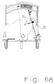
- FIGS. 6a and 6b show such, integrated in the switching tongue current fuse.
- FIG. 6a shows the switching tongue (4c), which in the region of the support point for the fixed point (2b) has a cross-sectional taper (4i), which is formed from a bore or expression.
- the divider block forms below the fixed point a switching chamber (2e), which separates the lower part of the switching tongue (4i ') during and after the current-related separation from the upper part (4i ") still connected to the soldering point, through the enclosure of the lower part the switching tongue, this area is electrically separated from the other parts by spacing and insulation ( FIG. 6b ).
Landscapes
- Engineering & Computer Science (AREA)
- Microelectronics & Electronic Packaging (AREA)
- Physics & Mathematics (AREA)
- Electromagnetism (AREA)
- Chemical & Material Sciences (AREA)
- Combustion & Propulsion (AREA)
- Fuses (AREA)
- Thermally Actuated Switches (AREA)
Description
- Die Erfindung betrifft eine Abtrennvorrichtung für einen Überspannungsableiter, deren Schaltbewegung durch eine Schaltzunge vollzogen wird, gemäß Patentanspruch 1.
- Unter dem Einfluss einer Erwärmung, deren Wärmequelle vorzugsweise ein zu überwachendes Überspannungsschutzbauteil bildet, wird das Lot verflüssigt und infolge einer dadurch ausgelösten Schaltbewegung eines speziell dafür vorgesehenen Teils der Abtrennvorrichtung, eine elektrische Verbindung aufgetrennt. Das Teil der Abtrennvorrichtung, welches die Schaltbewegung ausführt, ist z.B. nach
DE 295 19 313 U1 mittels einer in Schaltrichtung ausgerichteten Federkraft vorgespannt. Die Schaltbewegung erreicht ihren absoluten Endpunkt, sobald die Vorspannkraft dieser Feder aufgebraucht ist. - Von Abtrennvorrichtungen nach dem Stand der Technik ist als Nachteil bekannt, dass die Vorspannkraft, falls sie permanent auf die Lotstelle wirkt, bereits ohne thermischen Einfluss eine rein mechanische, nicht beabsichtigte Auslösung hervorrufen kann. Andererseits ist eine gewisse Vorspannkraft notwendig, um eine entsprechend wirkungsvolle Schaltbewegung zu erreichen, d.h. dass ein ausreichender Schaltweg (Trennabstand) und eine ausreichende Schaltgeschwindigkeit erreichbar sind.
- Sowohl der Schaltweg als auch die Schaltgeschwindigkeit sind Parameter, die die Leistungsfähigkeit (Schaltvermögen) der Abtrennvorrichtung bestimmen. Da mit zunehmendem Schaltweg eine rein mechanische Vorspannkraft rapide abnimmt, ist es sehr schwierig, einerseits über den gesamten Schaltweg eine ausreichende Schaltgeschwindigkeit sicherzustellen und andererseits die Vorspannungskraft auf die Lotstelle auf einen Wert zu begrenzen, der mit ausreichender Sicherheit eine rein mechanisch bedingte Fehlauslösung ausschließt. In der Praxis ist deshalb ein Kompromiss erforderlich, der abhängig von der Ausführung der Lotstelle, der Lotmenge und schließlich auch der Zusammensetzung des Lotes eine ausreichende Vorspannkraft zulässt. Dies setzt einen stabilen Fertigungsprozess voraus, der besonders im Hinblick auf die Einführung bleifreier Lote neu bestimmt werden muss und in der Regel eine weitere Reduzierung der Vorspannkraft erforderlich macht.
- Es ist daher Aufgabe der Erfindung, eine Lösung zu finden, die auf diese oben genannten geänderten Bedingungen mit einfachen Mitteln einzustellen ist. Zudem soll die Vorspannkraft soweit erhöht werden können, dass sich einerseits eine verbesserte Schaltleistung über den Schaltweg und die Schaltgeschwindigkeit ergibt, andererseits jedoch die Gefahr einer dadurch verursachten rein mechanischen Auslösung nicht besteht.
- Die Lösung der erfindungsgemäßen Abtrennvorrichtung für Überspannungsableiter mit erweitertem Funktionsumfang gemäß Anspruch 1 orientiert sich an folgenden Vorgaben:
- Eine Vorspannkraft F1, die im normalen Zustand des zu überwachenden Elementes auf die Lotstelle einwirkt soll idealerweise gleich Null oder zumindest sehr gering sein, so dass in diesem Zustand das Lot mechanisch dauerhaft nicht oder nur wenig belastet wird;
- Eine weitere Vorspannkraft F2 soll demgegenüber den eingeleiteten Auslötvorgang beschleunigen, um die Lotverbindung zu dem zu überwachenden Element möglichst schnell zu unterbrechen, indem sie mit zunehmender bzw. ab einer bestimmten Lottemperatur die Vorspannung F1 unterstützend verstärkt;
- Eine Schaltkraft F3 soll die während des Schaltvorgangs gegebenenfalls abklingenden Kräfte F1 / F2 unterstützen, indem sie idealerweise mit zunehmendem Schaltweg in dem Maße zunimmt, wie die resultierende Kraft F1 / F2 abnimmt.
- Die Kräfte F1 / F2 und F3 können als unabhängig voneinander organisierte Einzelkräfte aus einem oder auch aus mehreren gleichen oder unterschiedlichen Kraftspeichern erzeugt werden.
- Erfindungsgemäß wird die Gesamt-Vorspannkraft, die auf die Lotstelle wirkt, mindestens aus zwei Teilkräften zusammengesetzt, deren Kraftwirkungen (Wirkrichtungen) sich in Richtung Schaltbewegung bedarfsgerecht ergänzend verstärken.
- Neben einer ersten Vorspannkraft F1, die permanent auf die Lotstelle wirkt, wirken zudem eine oder mehrere weitere Kräfte bedarfsorientiert, indem sie z.B. bei normaler Lottemperatur nahezu wirkungslos sind und erst mit zunehmender Lottemperatur oder während des Abtrenn- bzw. Schaltvorgangs ihre Kraftwirkung mit einbringen. Diese bedarfsgerecht entwickelte Kräfteeinwirkung bzw. -verteilung kann zustands- oder temperaturabhängig stetig bzw. ab einem bestimmten Zustand der Schalterstellung und/oder einer bestimmten Temperatur schlagartig einsetzen.
- Voraussetzung hierfür ist, dass alle Teilkräfte vektoriell so ausgerichtet sind, dass sie sich in ihrer Kraftwirkung zum richtigen, dafür geeigneten Zeitpunkt ergänzen. Dazu beruht die Erfindung auf einer verstärkten Kraftwirkung auf das Abtrennelement während des gesamten Abtrennprozesses, d.h. während der Auslöt- und der nachfolgenden Schaltphase, die durch zusätzliche thermische und/oder mechanische Effekte beeinflusst bzw. unterstützt wird. Dies ist z.B. dann der Fall, wenn eine als Abtrennelement zur Anwendung kommende Schaltzunge selbst die thermische Kraftwirkung unterstützt oder diese Kraft gar aus ihr selbst heraus gebildet wird, indem sie z.B. aus einem Material hergestellt ist, das die dazu erforderlichen mechanischen/thermischen Eigenschaften aufweist.
- Die bei der Erfindung angewandte Lösung erfordert eine bestimmte Ausgestaltung einer solchen Schaltzunge, wobei sich die nachfolgend beschriebenen Ausführungen bzw. Varianten in diesem Sinne als vorteilhaft erwiesen haben.
- Die Schaltzunge ist aus einem Formteil gebildet, an dessen erstem auslaufendem Ende ein Kontaktbügel zur äußeren Kontaktierung mit einem Steckteil und an dessen zweitem auslaufendem Ende eine speziell ausgebildete oder ausbildbare Lotspitze angeformt ist. Diese Lotspitze wird über eine definierte Lotstelle mit dem aktiven, im Störfall als Wärmequelle dienenden Teil des Ableiters verbunden und bildet so eine elektrische/thermische Verbindung, die mithilfe der beschriebenen Vorspannkraft F1 bei entsprechendem Temperatureinfluss ausgelötet, eine Schaltbewegung ausführt.
Durch die Schaltbewegung wird der Stromkreis über den nun schadhaften Ableiter dauerhaft unterbrochen. - Da die Vorspannkraft F1 alleine erfindungsgemäß nur eine geringe Kraftwirkung auf die Lotstelle ausübt, soll eine zweite Vorspannkraft F2 bedarfsorientiert in den Abtrennvorgang eingreifen. Diese kann einerseits thermisch bewirkt sein, indem sie z.B. bereits während die Lotstelle "aufgeheizt" wird stetig oder schlagartig zunimmt und so den Auslötvorgang unterstützt. Andererseits kann der nach der Auslötung einsetzende Trennvorgang durch die Vorspannkraft F2 unterstützt werden, indem sie so wirkt, dass der Abtrennvorgang eine zusätzliche "Beschleunigung" erfährt, indem z.B. der Schaltweg durch eine weitere Öffnung der Trennstrecke durch Verformung der Schaltzunge vergrößert wird. Dadurch wird die elektrische Trennung verbessert, was besonders bei höheren Systemspannungen von Vorteil ist.
- Beide Lösungsansätze können vorteilhafterweise alleine oder in Kombination angewendet werden. Aus der Kombination ergibt sich zusätzlich eine gewisse Redundanz des Abtrennvorgangs, da beide Kräfte unabhängig voneinander den eingeleiteten Abtrennvorgang, nämlich den Auslötvorgang einerseits und den anschließenden Schaltvorgang andererseits unterstützen.
- Im Weiteren wird die zusammen mit der ersten Vorspannkraft F1 wirkende vorwiegend thermisch bedingte Vorspannkraft mit F2 und die nach dem Auslötvorgang zusammen mit F1 vorwiegend mechanisch wirkende Vorspannkraft als Schaltkraft F3 bezeichnet.
- Zur Bereitstellung der thermisch bedingten Vorspannkraft F2 besteht die Schaltzunge aus einem metallischen, elektrisch leitfähigen Material, das unter Wärmeeinfluss verformbar ist. Solche Metalle weisen nach dem Stand der Technik zwei verschiedene stabile Formzustände auf, die sich temperaturabhängig einstellen. Im Falle der Schaltzunge entspricht ein erster stabiler Zustand, der sich unter Normalbedingen ergibt, dem geschlossenen Zustand der Abtrennvorrichtung. Seine Kraftwirkung ist in dieser Stellung so gerichtet, dass er keine oder nur eine geringe zusätzliche Vorspannkraft erzeugt. Der zweite stabile Zustand, der sich unter Wärmeeinfluss einstellt, entspricht dagegen dem geöffneten Zustand der Abtrennvorrichtung, so dass mit zunehmender Erwärmung die Vorspannung ansteigt (stetig bzw. sprunghaft) und damit die mechanische Vorspannung auf die Lotstelle verstärkt. So wird eine bedarfsgerechte Vorspannung erzeugt, die letztlich auch für sich alleine gesehen zu hohen Schaltgeschwindigkeiten auch bei großen Schaltwegen führt.
- Für die Bereitstellung einer solchen Funktion sind z.B. sogenannte Bi-Metalle oder Memorymetalle geeignet. Während Bi-Metalle aus zwei Metallen zusammengesetzt sind, die sich unter Wärmeeinfluss unterschiedlich ausdehnen und somit das gesamte Teil in eine vorbestimmbare Richtung verformen, bestehen die Memorymetalle aus einer Metalllegierung (z.B. Nickel/Titan). Im Gegensatz zu den Bimetallen, wo sich mit steigender Temperatur das Bestreben in den zweiten stabilen Zustand überzugehen stetig zunimmt, weisen die Memorymetalle einen bestimmten Temperaturpunkt auf, bei dem sie sich schlagartig in der Art einer Schaltbewegung vom einen in den anderen Zustand bewegen und dort auch verbleiben, wenn die Temperatur, die zur Auslösung geführt hat, wieder abgefallen ist.
Bei der Ausführung mit einem Bimetall muss ggf. für den Fall der Abkühlung eine Rückhaltung vorgesehen werden, die das Wiedereinschalten der Abtrennvorrichtung verhindert. Ansonsten würde sich der Vorgang der Abtrennung zyklisch wiederholen. - Als weitere Ausgestaltung ist die Ausführung einer Schaltzunge denkbar, die selbst zusätzlich zu dem erwähnten thermischen Effekt einer Vorspannkraft F2 auch die erste, mechanisch bedingte Vorspannkraft F1 erzeugt, indem sie ganz oder teilweise aus einer Kombination eines der erwähnten thermischen Materialien mit einem federnden Material besteht. Bei einer solchen Ausführung kann sowohl ein bestimmter Bereich als auch die gesamte Schaltzunge in Sandwich-Bauweise mit dem thermisch reagierenden Metall ausgestattet sein. Eine mechanische Zug- oder Druckfeder zur Erzeugung der Vorspannkraft F1 wird dabei unter Umständen durch den federnden Effekt des Schaltzungenmaterials ersetzt. Insgesamt ist die erzielbare Wirkung einer solchen Kombination aber die gleiche wie bei der Ausführung nach der ersten Variante mit den funktionell getrennten Elementen zur Erzeugung der Kraftwirkung F1/F2. Ein Vorteil kann sich bei bestimmten Anwendungen ergeben, bei denen z.B. die Gefahr besteht, dass sich die mechanische Aufhängung der Feder für die Vorspannkraft F1 löst (z.B. durch mechanischen Erschütterungen) oder die Platzverhältnisse eine kompakte Ausführung der erfindungsgemäßen Abtrennvorrichtung erfordern.
- Wie bereits erwähnt, nimmt die Vorspannkraft F1 während der Schaltbewegung mit zunehmendem Schaltweg stetig ab. Dieser Effekt kann von der Vorspannkraft F2 nur teilweise kompensiert werden, da sich diese Teilkraft nur in der Auslötphase entfaltet und nachdem durch den Abtrennvorgang die Wärmezuführung unterbrochen wird, auch diese Kraft mehr oder weniger stetig abnimmt. Um zu verhindern, dass dadurch der Kräfteeintrag insgesamt für eine effektive Schaltbewegung über den gesamten Schaltweg nicht mehr ausreicht, ist gemäß der Erfindung eine weitere Kraft F3 vorgesehen, die sich während des Schaltvorgangs entfaltet und so die nachlassende Wirkung von F1 bzw. F2 zumindest teilweise kompensiert.
Die Bereitstellung dieser weiteren Kraft erfolgt ausschließlich während des Schaltvorgangs und entfaltet sich gegenüber den Vorspannkräften F1/F2 richtungsgleich, jedoch zeitlich versetzt invers. Sie wird aus der Bewegung der Schaltzunge abgeleitet indem durch eine stetige Verlagerung eines Kraftübertragungspunktes entlang der Schaltzunge das einwirkende Kräfteverhältnis durch veränderte Kraft- und oder Hebelwirkungen so beeinflusst wird, dass die daraus resultierende Kraft F3 mit zunehmendem Schaltweg stetig zunimmt. - Die Erfindung soll nachstehend anhand von Ausführungsbeispielen und den
Figuren 1 bis 6 näher erläutert werden. - Die nachfolgenden Ausführungsbeispiele beziehen sich ausgehend von einer gemeinsamen Grundversion auf drei Varianten der Erfindung, anhand derer die relevanten Funktionen, sowie weitere Details beschrieben und dargestellt werden.
- Die Erfindung stellt eine Abtrennvorrichtung für Überspannungsableiter mit erweitertem Funktionsumfang dar, der darin besteht, dass eine erste Vorspannkraft F1 nach dem Stand der Technik durch mindestens eine zweite, erfindungsgemäße Vorspannkraft F2 oder Schaltkraft F3 bedarfsgerecht unterstützt wird, um die Auslöse- sowie Schaltcharakteristik dahingehend zu verbessern, dass einerseits die Kraftwirkung auf die Lotstelle bei normaler Umgebungstemperatur vermindert und andererseits der Abtrennweg bzw. die Abtrenngeschwindigkeit gegenüber dem Stand der Technik erhöht ist. Die Abtrennmittel der erfindungsgemäßen Abtrennvorrichtung befinden sich zusammen mit dem zu überwachenden Überspannungs-Schutzelement bevorzugt in dem aufsteckbaren Oberteil eines zweiteiligen Gehäuses, sind aber prinzipiell auch einer einteiligen Anordnung realisierbar ist. Zudem weist das Oberteil Mittel zur Kontaktierung mit einem Unterteil und ein Anzeigefenster auf, an dem der Schaltzustand der Abtrennvorrichtung optisch angezeigt wird. Das Unterteil, kontaktiert über entsprechende Gegenkontakte das Oberteil und weist zudem Anschlussmittel für die äußeren Anschlüsse auf.
- Das aktive Element stellt dabei ein überspannungsbegrenzendes oder ein überspannungsschaltendes Bauteil dar, das von der Abtrennvorrichtung auf Überschreitung einer bestimmten Erwärmungstemperatur überwacht wird. Die Überschreitung vorgegebener Temperaturwerte wird als Defektzustand des aktiven Bauteils (z.B. Funkenstrecke und/oder Varistor) gewertet, was dessen Trennung von der Energiezufuhr über die Abtrennvorrichtung erfordert.
-
Figur 1a zeigt das Oberteil einer grundlegenden Ausführung eines steckbaren Überspannungsableiters, auf der die Erfindung im Wesentlichen aufbaut. - Hierbei besteht das Oberteil aus dem steckbaren Einsatz (1) mit angeformten äußeren Steckkontakten zur Kontaktierung mit dem Unterteil, an dem die Leitungszuführung der äußeren Anschlüsse erfolgt.
Die beiden äußeren Steckkontakte führen ins Gehäuseinnere und kontaktieren dort beidseitig das Ableiterelement (5). Erfindungsrelevant ist dabei, dass beide Kontaktstücke (4, 6) aus einem einzigen Stück als Stanz-, Zieh- oder Prägeteil aus einem vorzugsweise thermisch verformbaren und / oder federnden und dennoch gut leitfähigen Material bestehen, an dessen Ende bzw. Ausprägung jeweils Kontaktfedern (4b, 6b) oder Kontaktbügel (6a) zur Kontaktierung des Unterteils bzw. des Ableiterelementes (5) angeformt sind. - Ein erstes der beiden Kontaktstücke (4) ist in seiner Ausführung bzw. Ausgestaltung als Schaltzunge (4c) einer Abtrennvorrichtung mit erweiterten Eigenschaften ausgebildet, wobei eine Ausgestaltung der Schaltzunge (4c) als Schiene einmal ohne Ausprägung und bei einer weiteren Ausführung mit einer mittig angeordnete Ausprägung ausgebildet ist. Wesentlich ist dabei, dass beide Ausführungen der Kontaktstücke (4) aus einem einzigen Teil bestehen. An deren Ende befindet sich die Lotkontaktstelle (4d), deren Lotverbindung (4f) bei einer mit einer Erwärmung einhergehenden Überlastung des Ableiterelementes (5) an dessen Kontakt (5a) durch Wärmeübertragung aufschmilzt und mit einer Schaltbewegung der Schaltzunge (4c) die beabsichtigte Abschaltung bewirkt.
- Die Schaltbewegung der Schaltzunge (4c) resultiert aus einer Federspannung, die indirekt über einen Abtrennbock (2) eine Vorspannung auf die Schaltzunge (4c) und damit auf die Lotkontaktstelle (4d) ausübt. Diese Vorspannung entspricht der Vorspannkraft F1. Durch die Drehbewegung des Abtrennbocks (2) führt die abgetrennte Schaltzunge (4c) eine entsprechend schnelle Schaltbewegung über einen großen Öffnungsweg aus und stellt damit eine sichere Trennung zwischen dem Ableiterelement (5) und der durch die Schaltzunge (4c) gebildeten Leitungszuführung her. Gleichzeitig wird die vom Abtrennbock (2) ausgeführte Drehbewegung in ihrer Endstellung (1b) in einem Sichtfenster (1a) angezeigt, so dass nach außen hin die Schaltstellung des Abtrennbocks (2) anhand seiner Schaufläche (2d) als Auslösezustand erkennbar ist.
- Die Federvorspannung F1 für die Schaltzunge (4c) wird durch eine Feder (3) erzeugt, die ihren Festpunkt am Ende einer Gehäusenut (4a) hat. Die so von der Feder erzeugte Druckkraft wirkt auf den Abtrennbock (2) am Punkt (2c), der wiederum auf das Drehlager (2a) des Abtrennbocks wirkt und so die bereits erwähnte Drehbewegung ermöglicht.
Zunächst wirkt also die Federvorspannung F1 über den Abtrennbock (2) auf die Schaltzunge (4c) und damit auf die Lotkontaktstelle (4d). Eine weitere Unterstützung kann sie dadurch erfahren, dass die Schaltzunge (4c) selbst eine Vorspannung erzeugt, die aus einer Federspange oder aus einem Bimetall- oder Memorymetallstreifen bestehen kann. Während die Wirkung der Federspange hauptsächlich in der Schaltphase zum Tragen kommt, können thermisch verformbare Metalle, die so zusammengestellt sind, dass sie (mindestens) zwei stabile, temperaturabhängige Stellungen oder Ausformungen annehmen können, zur Unterstützung des Auslötvorgangs herangezogen werden. Dieser Effekt wird bei der Erfindung so genutzt, dass die Schaltzunge mit zunehmender Temperatur eine zunehmende Zugkraft F2 in Schaltrichtung erfährt und somit zuzüglich zur Federkraft F1 die Vorspannung erhöht, was den eingeleiteten Auslöt- und den nachfolgenden Abtrenn- bzw. Schaltvorgang positiv beeinflusst. Die durch die Kombination F1/F2 erzeugte Vorspannung der Schaltzunge hat nicht nur verstärkende Wirkung auf den Auslötvorgang, sondern erhöht zusätzlich die Zuverlässigkeit der Auslösung eines Schaltvorgangs durch zwei unabhängig einwirkende, gleichgerichtete Kräfte. - Die Lotstelle, die die Schaltzunge mit dem Ableiterelement verbindet, ist so ausgelegt und hergestellt, dass die Abtrennung sicher und zu einem Zeitpunkt erfolgt, bei dem noch keine thermischen Schäden durch ein überhitztes Ableiterelement abzusehen sind. Dieser Punkt wird zunächst durch die Wahl des Lotes bestimmt, wobei auch die beschriebene mechanische Vorspannung einen wesentlichen Anteil dazu liefert. Weiterhin müssen die Lotmenge an der Lotstelle (4f) (siehe
Figur 1b ) und die Wärmeverteilung an der Lotkontaktstelle optimiert sein.
Dazu ist zunächst die Lotkontaktstelle (4d) so ausgeformt, dass sie nur eine begrenzte Menge Lot aufnimmt, indem das Ende der Schaltzunge (4c) als Kontaktmesser (4d'), das als Gegenkontakt in einen schlitzförmigen Durchbruch (5c) eintaucht und mit seinem durchragenden Teil mit dem Kontakt (5a) des aktiven Elementes (5) verlötet wird, ausgebildet ist. Um eine optimale Wärmeverteilung zu erreichen, werden bevorzugt hochwärmeleitfähige Metalle oder Metalllegierungen bzw. Überzüge zumindest oder ausschließlich im Bereich der Lotkontaktstelle (4d) verwendet. - Das zweite Kontaktstück (6) ist so ausgeformt, dass es über entsprechende Abstützungen in dem Gehäusehalbteil, welches für die Aufnahme der Bauteile ausgebildet ist, einen Kontaktdruck über den Bügel (6a) auf die Kontaktfläche (5b) des Ableiterelementes (5) ausübt bzw. mit diesem Kontaktstück verlötet ist. Die Abstützungen bestehen aus miteinander verflochtenen Stegen, die gleichzeitig die Festigkeit des Gehäusehalbteiles (1) erhöhen, so dass ein kontinuierlicher Kontaktdruck auch durch eine entsprechende Steifigkeit des Trägergehäuses sichergestellt ist.
- Durch die Stege im tragenden Gehäusehalbteil werden beide Kontaktstücke (4, 6) geführt und in ihrer Lage gehalten. Gleichzeitig wirken die Stege in bestimmten Bereichen als Isolation für die Kontaktstücke bzw. stützen oder verstärken dort deren Form und ermöglichen so, dass die Kontaktstücke z.B. im Bereich der Steckkontakte mechanisch belastet werden können, ohne sich dadurch zu verformen.
- Die Erzeugung der erfindungsgemäßen Schaltkraft F3 wird anhand der
Figuren 2 bis 4 erklärt. Sie entfaltet ihre Wirkung sobald der Auslötvorgang vollzogen ist und sich die Schaltzunge in Richtung Endstellung für den geöffneten Zustand bewegt. Sie wirkt also wie die Vorspannkraft F2 bedarfsorientiert jedoch zeitversetzt zusammen mit F1. - Die betreffenden Ausführungen in den
Figuren 2 bis 4 entsprechen weitestgehend der Grundversion nachFigur 1 , weshalb hier nur diejenigen Elemente bezeichnet sind, die im unmittelbaren Zusammenhang mit der beschriebenen Funktion der jeweiligen Version stehen. Gemeinsame erfindungswesentliche Merkmale dieser drei erweiterten Funktionen sind - ein Festpunkt (2b) auf dem Abtrennbock, der die von den Vorspannkräften F1/F2 erzeugte und über den Abtrennbock übertragene, zunächst statische und nach dem Auslötvorgang in eine Drehbewegung umgesetzte Kraft abhängig von der Schaltstellung der Schaltzunge an einem bestimmten Punkt überträgt und dadurch eine sich stetig erweiternde Hebelkraft erzeugt,
- bestimmte Modifikationen der Schaltzunge, die eine gespeicherte statische Energie im Zuge der Schaltbewegung in eine richtungsgleiche Bewegungsenergie umwandeln und so die abklingenden Vorspannkräfte unterstützen.
- Die
Figuren 2a und2b zeigen ein erstes Beispiel der Erfindung jeweils im geschlossen und im ausgelösten Zustand.
Das erfindungswesentliche Merkmal dieses Ausführungsbeispiels sind zwei unterschiedlich angeordnete Drehpunkte, von denen ein erster am Punkt (4e) der Schaltzunge und ein zweiter am Punkt (2a) dem Abtrennbock zugeordnet ist. Die Kraftwirkung von F1 spannt im nicht ausgelösten Zustand über einen Festpunkt (2b) am Abtrennbock die Schaltzunge in Richtung der Schaltbewegung vor. Nach vollzogener Auslötung wird unter Einwirkung der Kraft F1 über den Festpunkt (2b) auf der Schaltzunge die Abtrennung eingeleitet, wobei sich die Krafteinwirkung die der Festpunkt auf die Schaltzunge ausübt mit zunehmendem Schaltweg in Richtung Abtrennkontakt (4d) bewegt. Diese Verlagerung der Kraftübertragung bewirkt eine Änderung der Kräfteaufteilung über die Länge der Schaltzunge zwischen dem Drehlager am Punkt (4e) und dem Auslötkontakt (4d), indem sich die Länge eines Hebelarmes L mit zunehmendem Schaltweg ausgehend von einer ausgeglichenen mittleren Position L1 in Bild 2a in eine ungleichgewichtige obere Position L2 in Bild 2b erstreckt.
So wird die bei zunehmendem Schaltweg abnehmende Federkraft F1 soweit kompensiert, dass sich trotzdem ein funktionell einwandfreier Verlauf des Abtrennvorgangs einstellt. Durch die anfänglich ausgeglichene mittlere Position L1 der Kraftübertragung über den Festpunkt auf die Schaltzunge kann die Vorspannkraft F1 gegenüber einer Abtrennvorrichtung nach dem Stand der Technik wesentlich reduziert sein. - Die
Figuren 3a und3b zeigen ein zweites Beispiel der Erfindung jeweils im geschlossen und im ausgelösten Zustand. Der Auslösevorgang bis zu der inFigur 3b dargestellten Position der Schaltzunge ist bis dahin identisch mit demjenigen, wie er inFigur 2a /2b bereits beschrieben wurde. Darüber hinaus weist diese Variante der Erfindung eine Zusatzfunktion auf, die ab dieser Position der Schaltstellung, die ja bereits die Endstellung der Drehbewegung durch den Abtrennbock darstellt eine weitere Verlängerung des Schaltweges bewirkt. Diese Schaltstellung ist inFigur 3c dargestellt. - Die hierfür zur Anwendung kommende Schaltzunge (4c) (
Figur 3d/3e ) wird aus einem Federmaterial ausgeformt, das in einem bestimmten Bereich eine Ausprägung mit einem überbogenen Steg (4h) aufweist. Der überbogene Steg wirkt als integrierte Federspange. Durch die mechanische Vorspannung, die die Schaltzunge durch die Überbiegung des Steges bzw. der Federspange erfährt, wirkt im eingelöteten Zustand zunächst eine Vorspannkraft (F2') in Richtung Lotstelle, wodurch die Vorspannung in Schaltrichtung durch die Federkraft F1 reduziert ist. Nachdem der Auslötvorgang abgeschlossen ist, setzt sich die Schaltzunge unter dem überwiegenden Einfluss von F1 in gewohnter Weise von der Lotstelle durch eine Schaltbewegung in Richtung Endstellung ab. Ab einer bestimmten Schaltstellung erfährt die Überbiegung (4h) dadurch eine Überdehnung, so dass sie schlagartig in die entgegengesetzte Richtung S2' kippt, wodurch die Schaltzunge insgesamt eine Kippbewegung durch Verformung des Steges in Richtung Endstellung vollzieht und damit den Schaltweg über die eigentliche Endstellung der Schaltbewegung S1 hinaus um den Betrag S2 zusätzlich vergrößert (Figur 3c ). - Die
Figuren 4a /4b zeigen eine dritte Variante der Erfindung jeweils im eingelöteten und im ausgelöteten Zustand. Diese Variante weist eine etwa S-förmig vorgebogene Schaltzunge (4c) auf, wie sie inFigur 4b im ausgelöteten Zustand zu erkennen ist.
Im geschlossenen Zustand nachFigur 4a wird der vordere Bereich der Schaltzunge in eine U-Form gebogen, deren offenes Ende (4d') in einen Schlitz (5c) der Lotkontaktfahne (5a) ragt und darin verlötet wird. Auch hier überträgt der Festpunkt (2b) des Abtrennbocks die Vorspannkraft F1 der Feder auf die Schaltzunge und verändert während der der Auslötung folgenden Trennbewegung seinen Angriffspunkt so, dass er die Trennbewegung unterstützt. Als Folge davon wird das verlötete Ende der Schaltzunge aus dem Schlitz der Lotkontaktfahne herausgezogen und vollzieht die Trennung ebenfalls durch eine Verformung der Schaltzunge, indem sie wieder ihre ursprüngliche S-Form einnimmt. Während das ausgelötete Ende dadurch nach oben schnappt, wird die Schaltbewegung bis zur Endstellung (1b) des Abtrennbocks fortgeführt. -
Figur 5a zeigt beispielhaft das Zusammenwirken der einzelnen Teilkräfte F1, F2 und F3 während eines Auslötvorganges durch Erwärmung T des zu überwachenden Ableiterelementes mit anschließender Abtrennung der Schaltzunge und dem Schaltweg, den die Schaltzunge bis zum Endanschlag zurücklegt. - Der Auslötvorgang liegt im Bereich A. Die Erwärmungstemperatur T des Ableiters steigt dabei beginnend bei der Umgebungstemperatur Tu an, bis die Auslöttemperatur TA erreicht ist. Durch die im Bereich B zum Zeitpunkt t2 eingeleitete Abtrennung von der Energiezufuhr kühlt der Ableiter über die Zeit wieder ab. So wird eine Überhitzung des Gesamtsystems, die sich im ungünstigsten Fall bzw. fehlender Abtrennvorrichtung zu einer Brandgefährdung entwickeln könnte, vermieden.
Während des Auslötvorgangs steigt die Kraftwirkung der Vorspannkraft F2 kontinuierlich an, während die Vorspannkraft F1 permanent auf die Schaltzunge und damit auf die zu diesem Zeitpunkt noch nicht aufgelötete Lotstelle wirkt. - An der Schnittstelle Bereich A zu Bereich B ist zum Zeitpunkt t2 der Auslötvorgang abgeschlossen. Die Schaltzunge wird zunächst maßgeblich unter Einwirkung der mit zunehmendem Schaltweg nachlassenden Kräfte F1 und F2 in Richtung Endstellung t3 bewegt, während die Kraft F3 in diesem Bereich mit Mitteln, die in den Erläuterungen zu den
Figuren 2 bis 4 beschrieben sind, bis zur Endstellung ansteigt. - Das Diagramm
Figur 5a zeigt zudem deutlich, dass die Kraft F2 im Wesentlichen den Auslötvorgang (Bereich A) unterstützt. Weiteres Ziel der Erfindung ist allerdings auch, dass für den Schaltvorgang (Bereich B) eine weitere Kraft zur Wirkung kommt, die die mit zunehmendem Schaltweg nachlassende Federkraft von F1 unterstützt oder ersetzt, um eine hohe Schaltgeschwindigkeit bzw. einen großen Schaltweg zu erzielen. Dazu dient die Schaltkraft F3 die nach den MittelnFigur 2 bis Figur 4 bereitgestellt wird. -
Figur 5b zeigt den Verlauf der aus den Teilkräften F1, F2 und F3 resultierenden Gesamtkraft FRG im Vergleich zum Verlauf der Vorspannkraft F1. Man erkennt, dass die zusätzlichen Maßnahmen der Erfindung gegenüber dem Stand der Technik (hier durch den Verlauf von F1 repräsentiert) deutliche Vorteile aufweist. - Die erläuterten Ausführungen einer Abtrennvorrichtung für Überspannungsableiter mit erweitertem Funktionsumfang gehen davon aus, dass sich das zu überwachende Überspannungsschutzelement unter dem Einfluss einer Belastung oder Beschädigung so verhält, dass es sich übermäßig erhitzt. Diese Überhitzung bildet praktisch die Vorraussetzung, dass die Lotstelle aufschmilzt und letztlich in der beschriebenen Art und weise das defekte Bauteil von der Versorgungsspannung abtrennt. Eine auf diese Art wirkende Abtrennvorrichtung kann deshalb auch nur dann wirkungsvoll eingesetzt werden, wenn eine relativ träge Abschaltung ausreicht, was in den meisten Fällen auch tatsächlich der Fall ist, zumal die meistens extern im Stromnetz vorzusehenden Stromsicherungen die Schnellabschaltung (z.B. bei Kurzschluss) übernehmen.
- Eine Abtrennvorrichtung mit erweitertem Funktionsumfang sollte jedoch so konzipiert sein, dass auch ein eventueller Kurzschluss über das Ableiterelement erkannt und rechtzeitig abgeschaltet werden kann. Diese Maßnahme hat folgende Vorteile:
- Es ist kein externer Kurzschlussschutz erforderlich, bzw. die Anwendung ist von dessen Bemessung unabhängig;
- die Schaltcharakteristik des integrierten Kurzschlussschutzes kann mit der der thermischen Abtrennung abgestimmt (koordiniert) werden;
- die thermische Abtrennung und die Kurzschlussabtrennung können am Überspannungsableiter angezeigt werden;
- Ein Kurzschluss des Überspannungsableiters führt nicht zwangsläufig zur Abschaltung der Stromversorgung der Verbraucheranlage durch die Stromkreissicherung (koordinationsabhängig).
- Wie auch immer besteht durch eine weitere Modifikation der Schaltzunge die Möglichkeit, eine Kurzschlusssicherung einzurichten. Dazu wird der Querschnitt der Schaltzunge an einer dafür geeigneten Stelle verjüngt. Der Querschnitt dieser Verjüngung bestimmt den Strom, der zu einer strombedingten Abschaltung führt.
- Der bei der strombedingten Abschaltung an der Trennstelle auftretende Lichtbogen wird, um dessen Auswirkungen zu begrenzen, am Aufbau behindert. Dazu wird in konventionellen Stromsicherungen eine Löschsandfüllung vorgesehen, die die Lichtbogenstelle umgibt und den entstehenden Lichtbogen soweit herunterkühlt, dass er sich gar nicht erst ausweiten kann.
Nach dem Stand der Technik ist von Trennschaltern allerdings auch bekannt, die Lichtbogenkühlung durch so genannte Funkenlöschkammern herbeizuführen. Hier wird der Lichtbogen in Teillichtbögen aufgeteilt und mittels Kühlbleche abgekühlt. - Eine weitere Möglichkeit bietet eine Löscheinrichtung, die unter dem thermischen Einfluss des Lichtbogens ein Löschgas freisetzt.
- Um den Lichtbogen an der strombedingten Schmelzstelle der Schaltzunge zu beherrschen, sind bei der Erfindung zwei Maßnahmen vorgesehen.
Zum einen ist der Abtrennbock so ausgeführt, dass er sich zwischen die aufgetrennten Teile der Schaltzunge schiebt, wobei der untere Teil hohlwandig ausgebildet ist und den abgetrennten unteren Teil der Schaltzunge in Art einer Schaltkammer umschließt. Damit bietet sich dem Lichtbogen kein weiterer Fußpunkt, wodurch er unterbrochen wird. - Zum zweiten besteht der Abtrennbock bzw. zumindest die Hohlkammer aus einem Werkstoff, der unter dem Einfluss des Lichtbogens ein Löschgas freisetzt, welches zusätzlich die Ausdehnung des Lichtbogens durch Kühlung unterbindet.
- Die
Figuren 6a und6b zeigen eine solche, in die Schaltzunge integrierte Stromsicherung. -
Figur 6a zeigt die Schaltzunge (4c), die im Bereich des Auflagepunktes für den Festpunkt (2b) eine Querschnittsverjüngung (4i) aufweist, die aus einer Bohrung oder Ausprägung gebildet ist. Der Abtrennbock bildet unterhalb des Festpunktes eine Schaltkammer (2e) aus, die den unteren Bereich der Schaltzunge (4i') während und nach der strombedingten Abtrennung vom oberen, noch mit der Lotstelle verbundenen Teil (4i") abtrennt. Durch die Einhausung des unteren Teils der Schaltzunge ist dieser Bereich elektrisch von den übrigen Teilen durch Beabstandung und Isolierung getrennt (Figur 6b ). -
- 1
- steckbarer Einsatz
- 1a
- Sichtfenster
- 1b
- Endstellung
- 2
- Abtrennbock
- 2a
- Drehlager [2]
- 2b
- Festpunkt
- 2c
- Kraftübertragung [3]
- 2d
- Schaufläche
- 2e
- Schaltkammer
- 3
- Feder
- 4
- Kontaktstück
- 4a
- Gehäusenut, Anschlag für [3]
- 4b
- Steckkontakt, Kontaktfeder
- 4c
- Schaltzunge
- 4d
- Lotkontaktstelle, Abtrennkontakt
- 4d'
- Kontaktmesser
- 4e
- Drehpunkt
- 4f
- Lotverbindung
- 4g
- ----
- 4h
- überbogener Steg [4c]
- 4i
- Querschnittsverjüngung [4c]
- 4i'
- Schaltzunge, unterer Bereich
- 4i"
- Schaltzunge, oberer Bereich
- 5
- Ableiterelement
- 5a
- Ableiterkontakt
- 5b
- Kontaktfläche
- 5c
- Durchbruch
- 6
- Kontaktstück
- 6a
- Kontaktbügel
- 6b
- Steckkontakt, Kontaktfeder
Claims (3)
- Abtrennvorrichtung für einen Überspannungsableiter, deren Schaltbewegung durch eine Schaltzunge vollzogen wird, die über eine permanent wirkende Federkraft in Gegenrichtung zu der über ein Schutzlot hergestellten Haltekraft ausgerichtet ist,
dadurch gekennzeichnet, dass
die auf die Schaltzunge oder deren Lotstelle zur Erzeugung einer Auslöt- bzw. Schaltkraft über einen Abtrennbock (2) indirekt einwirkende permanente Vorspannkraft (F1) durch mindestens eine weitere, unabhängig davon wirkende weitere Vorspannkraft (F2) sowie einer ergänzenden Schaltkraft (F3) mit gleicher Wirkrichtung unterstützt wird, wobei sich deren Kräfteverteilung so einstellt, dass im Ruhezustand eine geringe resultierende Kraft auf die Lotstelle wirkt und eine möglichst große resultierende Kraft die Schaltbewegung während des Auslötvorgangs vollzieht, indem die Vorspannkraft (F2) in der Auslötphase durch die Ausbildung der Schaltzunge aus einem Memory- oder Bimetallstreifen oder eine Schaltzunge (4c) aus einem Federmaterial, welches eine Ausprägung mit einem überbogenen Steg (4h) aufweist, bereitgestellt und die ergänzende Schaltkraft (F3) nach Beendigung des Auslötvorgangs durch Verlagerung eines Kraftübertragungspunktes (2b) der auf die Schaltzunge hervorgerufenen Vorspannung (F1) resultierenden Hebelkraft gebildet ist. - Abtrennvorrichtung nach Anspruch 1,
dadurch gekennzeichnet, dass
die Verlagerung des Kraftübertragungspunktes aus einer Drehbewegung abgeleitet ist. - Abtrennvorrichtung nach Anspruch 2,
dadurch gekennzeichnet, dass
der Abtrennbock ein Drehlager aufweist.
Priority Applications (1)
| Application Number | Priority Date | Filing Date | Title |
|---|---|---|---|
| SI200731785A SI2011128T1 (sl) | 2006-04-26 | 2007-04-03 | Postopek dimenzioniranja odklopnega stikala za prenapetostni odvodnik |
Applications Claiming Priority (3)
| Application Number | Priority Date | Filing Date | Title |
|---|---|---|---|
| DE102006019498 | 2006-04-26 | ||
| DE102006036598A DE102006036598A1 (de) | 2006-04-26 | 2006-08-04 | Verfahren zur Dimensionierung einer Abtrennvorrichtung für Überspannungsableiter |
| PCT/EP2007/053198 WO2007125000A1 (de) | 2006-04-26 | 2007-04-03 | Verfahren zur dimensionierung einer abtrennvorrichtung für überspannungsableiter |
Publications (2)
| Publication Number | Publication Date |
|---|---|
| EP2011128A1 EP2011128A1 (de) | 2009-01-07 |
| EP2011128B1 true EP2011128B1 (de) | 2016-03-30 |
Family
ID=38542467
Family Applications (1)
| Application Number | Title | Priority Date | Filing Date |
|---|---|---|---|
| EP07727670.7A Active EP2011128B1 (de) | 2006-04-26 | 2007-04-03 | Verfahren zur dimensionierung einer abtrennvorrichtung für überspannungsableiter |
Country Status (9)
| Country | Link |
|---|---|
| EP (1) | EP2011128B1 (de) |
| JP (1) | JP5059099B2 (de) |
| CN (1) | CN101427327B (de) |
| DE (1) | DE102006036598A1 (de) |
| ES (1) | ES2579908T3 (de) |
| PL (1) | PL2011128T3 (de) |
| RU (1) | RU2410781C2 (de) |
| SI (1) | SI2011128T1 (de) |
| WO (1) | WO2007125000A1 (de) |
Cited By (2)
| Publication number | Priority date | Publication date | Assignee | Title |
|---|---|---|---|---|
| DE102017129660A1 (de) | 2017-07-10 | 2019-01-10 | DEHN + SÖHNE GmbH + Co. KG. | Anordnung zum Monitoring des Zustandes von Überspannungsableitern |
| DE102018114564A1 (de) | 2018-06-18 | 2019-12-19 | Dehn Se + Co Kg | Abtrennvorrichtung für einen Überspannungsableiter |
Families Citing this family (16)
| Publication number | Priority date | Publication date | Assignee | Title |
|---|---|---|---|---|
| DE102008029670B4 (de) * | 2008-06-24 | 2016-10-20 | Phoenix Contact Gmbh & Co. Kg | Überspannungsschutzelement |
| DE102008048644B4 (de) * | 2008-08-01 | 2017-08-24 | DEHN + SÖHNE GmbH + Co. KG. | Überspannungsschutzgerät mit einem oder mehreren parallel geschalteten, in einer baulichen Einheit befindlichen überspannungsbegrenzenden Elementen |
| DE102009052400B3 (de) * | 2009-11-10 | 2011-05-12 | Phoenix Contact Gmbh & Co. Kg | Thermische Überlastschutzvorrichtung |
| DE102010038066B4 (de) * | 2010-08-06 | 2012-05-03 | Phoenix Contact Gmbh & Co. Kg | Thermische Überlastschutzanordnung |
| EP2541577A1 (de) * | 2011-06-30 | 2013-01-02 | Epcos Ag | Elektrisches Gerät |
| EP2541579B1 (de) | 2011-06-30 | 2015-11-04 | Epcos Ag | Elektrisches Gerät |
| DE102013202795C5 (de) * | 2013-02-20 | 2019-01-24 | Phoenix Contact Gmbh & Co. Kg | Reversible Abtrennvorrichtung |
| DE102013021936B3 (de) * | 2013-10-08 | 2015-02-12 | Dehn + Söhne Gmbh + Co. Kg | Kompakte, vorkonfektionierbare Überspannungsschutzvorrichtung |
| DE102015008136B4 (de) | 2014-09-05 | 2021-08-26 | Dehn Se + Co Kg | Schalteinrichtung für Überspannungsschutzgeräte |
| EP3166193B1 (de) | 2015-11-09 | 2018-01-31 | Dehn + Söhne Gmbh + Co Kg | Schalteinrichtung für überspannungsschutzgeräte |
| DE102016001767A1 (de) | 2015-11-09 | 2017-05-11 | DEHN + SÖHNE GmbH + Co. KG. | Schalteinrichtung für Überspannungsschutzgeräte |
| DE102018205549B3 (de) | 2018-04-12 | 2019-08-01 | Phoenix Contact Gmbh & Co. Kg | Abtrennelement und Ensemble aufweisend ein entsprechendes Abtrennelement und ein Überspannungsschutzelement |
| CN110553045A (zh) * | 2018-05-30 | 2019-12-10 | 杭州小米环境科技有限公司 | 阀座、锁止结构及防火止回阀 |
| DE202018006119U1 (de) | 2018-06-18 | 2019-04-11 | Dehn + Söhne Gmbh + Co. Kg | Abtrennvorrichtung für einen Überspannungsableiter |
| GB2619066A (en) * | 2022-05-26 | 2023-11-29 | Eaton Intelligent Power Ltd | Overvoltage protection device with improved integrated overtemperature protection |
| CN115473090B (zh) * | 2022-09-27 | 2025-09-05 | 南京淳科特来电新能源有限公司 | 一种新能源汽车充电设备防过充装置 |
Family Cites Families (17)
| Publication number | Priority date | Publication date | Assignee | Title |
|---|---|---|---|---|
| DE2735624A1 (de) * | 1977-08-06 | 1979-02-08 | Standard Elektrik Lorenz Ag | Ueberspannungsschutzvorrichtung fuer fernsprechanlagen |
| JPS57107253U (de) * | 1980-12-23 | 1982-07-02 | ||
| GB2096844A (en) * | 1981-04-10 | 1982-10-20 | Beswick Kenneth E Ltd | Electrical fuse |
| EP0076284A1 (de) * | 1981-04-10 | 1983-04-13 | Kenneth E Beswick Limited | Elektrische schmelzsicherung |
| JPS5895147U (ja) * | 1981-12-18 | 1983-06-28 | 松下電器産業株式会社 | 断路表示機構付サ−ジ吸収器 |
| JPS5916044U (ja) * | 1982-07-22 | 1984-01-31 | 東邦電気株式会社 | 回路しや断器の温度ヒユ−ズ装置 |
| JPS6094753U (ja) * | 1983-12-02 | 1985-06-28 | 本郷 萬蔵 | 温度ヒユ−ズ |
| DE4118738C1 (de) * | 1991-06-05 | 1992-12-24 | Krone Ag, 1000 Berlin, De | |
| JP2754334B2 (ja) * | 1994-06-22 | 1998-05-20 | ウチヤ・サーモスタット株式会社 | ヒューズスプリング内蔵サーモスタット |
| DE4437122C2 (de) * | 1994-10-01 | 1996-07-18 | Krone Ag | Überspannungsschutzstecker |
| CN2209383Y (zh) * | 1994-11-24 | 1995-10-04 | 西安无线电二厂 | 指示报警型浪涌吸收器 |
| DE29519313U1 (de) * | 1995-12-06 | 1996-01-25 | Dehn + Söhne GmbH + Co KG, 90489 Nürnberg | Überspannungsableiter |
| DE19717634C2 (de) * | 1997-04-25 | 2000-06-08 | Epcos Ag | Elektrisches Bauelement mit Sicherheitstrennvorrichtung |
| AT406207B (de) * | 1997-09-30 | 2000-03-27 | Felten & Guilleaume Ag Oester | Steckbarer überspannungsableiter |
| DE19819792A1 (de) * | 1998-05-04 | 1999-11-18 | Kopp Heinrich Ag | Mehrpoliger Schalter |
| DE10000617A1 (de) * | 2000-01-10 | 2001-07-12 | Abb Hochspannungstechnik Ag | Ueberspannungsableiter |
| CN2588521Y (zh) * | 2002-12-25 | 2003-11-26 | 王保巨 | 热爆式脱离器 |
-
2006
- 2006-08-04 DE DE102006036598A patent/DE102006036598A1/de not_active Withdrawn
-
2007
- 2007-04-03 CN CN2007800146088A patent/CN101427327B/zh not_active Expired - Fee Related
- 2007-04-03 WO PCT/EP2007/053198 patent/WO2007125000A1/de not_active Ceased
- 2007-04-03 JP JP2009507016A patent/JP5059099B2/ja not_active Expired - Fee Related
- 2007-04-03 SI SI200731785A patent/SI2011128T1/sl unknown
- 2007-04-03 RU RU2008145659/07A patent/RU2410781C2/ru not_active IP Right Cessation
- 2007-04-03 PL PL07727670.7T patent/PL2011128T3/pl unknown
- 2007-04-03 EP EP07727670.7A patent/EP2011128B1/de active Active
- 2007-04-03 ES ES07727670.7T patent/ES2579908T3/es active Active
Cited By (6)
| Publication number | Priority date | Publication date | Assignee | Title |
|---|---|---|---|---|
| DE102017129660A1 (de) | 2017-07-10 | 2019-01-10 | DEHN + SÖHNE GmbH + Co. KG. | Anordnung zum Monitoring des Zustandes von Überspannungsableitern |
| WO2019011631A1 (de) | 2017-07-10 | 2019-01-17 | Dehn + Söhne Gmbh + Co. Kg | Anordnung zum monitoring des zustandes von überspannungsableitern |
| DE102017129660B4 (de) | 2017-07-10 | 2024-04-11 | Dehn Se | Anordnung zum Monitoring des Zustandes von Überspannungsableitern |
| DE102018114564A1 (de) | 2018-06-18 | 2019-12-19 | Dehn Se + Co Kg | Abtrennvorrichtung für einen Überspannungsableiter |
| US11476071B2 (en) | 2018-06-18 | 2022-10-18 | Dehn Se | Disconnecting device for a surge arrester |
| DE102018114564B4 (de) | 2018-06-18 | 2023-01-19 | Dehn Se | Überspannungsableiter |
Also Published As
| Publication number | Publication date |
|---|---|
| CN101427327A (zh) | 2009-05-06 |
| CN101427327B (zh) | 2011-04-06 |
| DE102006036598A1 (de) | 2007-10-31 |
| EP2011128A1 (de) | 2009-01-07 |
| ES2579908T3 (es) | 2016-08-17 |
| RU2410781C2 (ru) | 2011-01-27 |
| JP5059099B2 (ja) | 2012-10-24 |
| PL2011128T3 (pl) | 2016-09-30 |
| SI2011128T1 (sl) | 2016-07-29 |
| RU2008145659A (ru) | 2010-06-10 |
| WO2007125000A1 (de) | 2007-11-08 |
| JP2009534804A (ja) | 2009-09-24 |
Similar Documents
| Publication | Publication Date | Title |
|---|---|---|
| EP2011128B1 (de) | Verfahren zur dimensionierung einer abtrennvorrichtung für überspannungsableiter | |
| DE602005000540T2 (de) | Überspannungs-Schutzeinrichtung | |
| EP1958304B1 (de) | Steckbarer überspannungsableiter | |
| DE19941190B4 (de) | Wärmeschutzsicherung | |
| DE102008013447B4 (de) | Überspannungsableiter mit einem Gehäuse und mindestens einem Ableitelement | |
| DE102011052805B4 (de) | Sicherung | |
| EP2126949A1 (de) | Auslösevorrichtung für eine thermosicherung | |
| EP0640242B1 (de) | Kontaktfederanordnung für ein relais zum führen und schalten hoher ströme | |
| EP3673497B1 (de) | Abtrennvorrichtung für einen überspannungsableiter | |
| DE102008049789B4 (de) | Kontaktvorrichtung mit unterschiedlichen Kontaktkräften in unterschiedlichen Betriebszuständen | |
| EP0938116B1 (de) | Schalter | |
| DE202007006934U1 (de) | Steckbarer Überspannungsableiter | |
| DE3823747C2 (de) | ||
| DE19909059A1 (de) | Schalter mit Verschweißsicherung | |
| DE2610951C3 (de) | Schutzschalter | |
| DE3729454C3 (de) | Kontaktelement für den Leistungsanschluß eines Schaltschrankeinschubs einer Niederspannungsschaltanlage | |
| EP3258231A1 (de) | Elektromechanisches schutzschaltgerät mit einer überlastauslöseeinrichtung | |
| EP0170186B1 (de) | Elektrische Sicherungseinrichtung mit einem Schmelzleiter | |
| DE19607756C1 (de) | Hochspannungs-Hochleistungs-Sicherung | |
| DE2414884A1 (de) | Thermischer mikroschalter | |
| EP2070169B1 (de) | Überspannungsableiter mit mindestens einem ableitelement, insbesondere einem varistor, sowie mit einer abtrennvorrichtung | |
| EP0264409A1 (de) | Vorrichtung zum schutz eines überspannungsableiters gegen thermische überlastung | |
| DE102008049472A1 (de) | Überspannungsableiter mit mindestens einem Ableitelement, insbesondere einem Varistor, sowie mit einer Abtrennvorrichtung | |
| WO2019077038A1 (de) | Überspannungsschutzgerät | |
| DE29913553U1 (de) | Elektrische Sicherung |
Legal Events
| Date | Code | Title | Description |
|---|---|---|---|
| PUAI | Public reference made under article 153(3) epc to a published international application that has entered the european phase |
Free format text: ORIGINAL CODE: 0009012 |
|
| 17P | Request for examination filed |
Effective date: 20080814 |
|
| AK | Designated contracting states |
Kind code of ref document: A1 Designated state(s): AT BE BG CH CY CZ DE DK EE ES FI FR GB GR HU IE IS IT LI LT LU LV MC MT NL PL PT RO SE SI SK TR |
|
| AX | Request for extension of the european patent |
Extension state: AL BA HR MK RS |
|
| 17Q | First examination report despatched |
Effective date: 20110901 |
|
| DAX | Request for extension of the european patent (deleted) | ||
| REG | Reference to a national code |
Ref country code: DE Ref legal event code: R079 Ref document number: 502007014668 Country of ref document: DE Free format text: PREVIOUS MAIN CLASS: H01C0007120000 Ipc: H01H0037760000 |
|
| GRAP | Despatch of communication of intention to grant a patent |
Free format text: ORIGINAL CODE: EPIDOSNIGR1 |
|
| RIC1 | Information provided on ipc code assigned before grant |
Ipc: H01H 37/76 20060101AFI20151126BHEP |
|
| INTG | Intention to grant announced |
Effective date: 20151216 |
|
| GRAS | Grant fee paid |
Free format text: ORIGINAL CODE: EPIDOSNIGR3 |
|
| GRAA | (expected) grant |
Free format text: ORIGINAL CODE: 0009210 |
|
| AK | Designated contracting states |
Kind code of ref document: B1 Designated state(s): AT BE BG CH CY CZ DE DK EE ES FI FR GB GR HU IE IS IT LI LT LU LV MC MT NL PL PT RO SE SI SK TR |
|
| REG | Reference to a national code |
Ref country code: GB Ref legal event code: FG4D Free format text: NOT ENGLISH |
|
| REG | Reference to a national code |
Ref country code: CH Ref legal event code: EP |
|
| REG | Reference to a national code |
Ref country code: AT Ref legal event code: REF Ref document number: 786177 Country of ref document: AT Kind code of ref document: T Effective date: 20160415 |
|
| REG | Reference to a national code |
Ref country code: IE Ref legal event code: FG4D Free format text: LANGUAGE OF EP DOCUMENT: GERMAN |
|
| REG | Reference to a national code |
Ref country code: FR Ref legal event code: PLFP Year of fee payment: 10 |
|
| REG | Reference to a national code |
Ref country code: DE Ref legal event code: R096 Ref document number: 502007014668 Country of ref document: DE |
|
| REG | Reference to a national code |
Ref country code: LT Ref legal event code: MG4D |
|
| PG25 | Lapsed in a contracting state [announced via postgrant information from national office to epo] |
Ref country code: FI Free format text: LAPSE BECAUSE OF FAILURE TO SUBMIT A TRANSLATION OF THE DESCRIPTION OR TO PAY THE FEE WITHIN THE PRESCRIBED TIME-LIMIT Effective date: 20160330 Ref country code: GR Free format text: LAPSE BECAUSE OF FAILURE TO SUBMIT A TRANSLATION OF THE DESCRIPTION OR TO PAY THE FEE WITHIN THE PRESCRIBED TIME-LIMIT Effective date: 20160701 |
|
| PGFP | Annual fee paid to national office [announced via postgrant information from national office to epo] |
Ref country code: ES Payment date: 20160518 Year of fee payment: 10 |
|
| REG | Reference to a national code |
Ref country code: NL Ref legal event code: MP Effective date: 20160330 |
|
| REG | Reference to a national code |
Ref country code: ES Ref legal event code: FG2A Ref document number: 2579908 Country of ref document: ES Kind code of ref document: T3 Effective date: 20160817 |
|
| PG25 | Lapsed in a contracting state [announced via postgrant information from national office to epo] |
Ref country code: BE Free format text: LAPSE BECAUSE OF NON-PAYMENT OF DUE FEES Effective date: 20160430 Ref country code: SE Free format text: LAPSE BECAUSE OF FAILURE TO SUBMIT A TRANSLATION OF THE DESCRIPTION OR TO PAY THE FEE WITHIN THE PRESCRIBED TIME-LIMIT Effective date: 20160330 Ref country code: LV Free format text: LAPSE BECAUSE OF FAILURE TO SUBMIT A TRANSLATION OF THE DESCRIPTION OR TO PAY THE FEE WITHIN THE PRESCRIBED TIME-LIMIT Effective date: 20160330 Ref country code: LT Free format text: LAPSE BECAUSE OF FAILURE TO SUBMIT A TRANSLATION OF THE DESCRIPTION OR TO PAY THE FEE WITHIN THE PRESCRIBED TIME-LIMIT Effective date: 20160330 |
|
| PGFP | Annual fee paid to national office [announced via postgrant information from national office to epo] |
Ref country code: SI Payment date: 20160401 Year of fee payment: 10 |
|
| PG25 | Lapsed in a contracting state [announced via postgrant information from national office to epo] |
Ref country code: NL Free format text: LAPSE BECAUSE OF FAILURE TO SUBMIT A TRANSLATION OF THE DESCRIPTION OR TO PAY THE FEE WITHIN THE PRESCRIBED TIME-LIMIT Effective date: 20160330 |
|
| PG25 | Lapsed in a contracting state [announced via postgrant information from national office to epo] |
Ref country code: IS Free format text: LAPSE BECAUSE OF FAILURE TO SUBMIT A TRANSLATION OF THE DESCRIPTION OR TO PAY THE FEE WITHIN THE PRESCRIBED TIME-LIMIT Effective date: 20160730 Ref country code: EE Free format text: LAPSE BECAUSE OF FAILURE TO SUBMIT A TRANSLATION OF THE DESCRIPTION OR TO PAY THE FEE WITHIN THE PRESCRIBED TIME-LIMIT Effective date: 20160330 |
|
| PG25 | Lapsed in a contracting state [announced via postgrant information from national office to epo] |
Ref country code: SK Free format text: LAPSE BECAUSE OF FAILURE TO SUBMIT A TRANSLATION OF THE DESCRIPTION OR TO PAY THE FEE WITHIN THE PRESCRIBED TIME-LIMIT Effective date: 20160330 Ref country code: PT Free format text: LAPSE BECAUSE OF FAILURE TO SUBMIT A TRANSLATION OF THE DESCRIPTION OR TO PAY THE FEE WITHIN THE PRESCRIBED TIME-LIMIT Effective date: 20160801 Ref country code: RO Free format text: LAPSE BECAUSE OF FAILURE TO SUBMIT A TRANSLATION OF THE DESCRIPTION OR TO PAY THE FEE WITHIN THE PRESCRIBED TIME-LIMIT Effective date: 20160330 |
|
| PGFP | Annual fee paid to national office [announced via postgrant information from national office to epo] |
Ref country code: CZ Payment date: 20160527 Year of fee payment: 10 Ref country code: PL Payment date: 20160426 Year of fee payment: 10 |
|
| REG | Reference to a national code |
Ref country code: CH Ref legal event code: PL |
|
| REG | Reference to a national code |
Ref country code: DE Ref legal event code: R097 Ref document number: 502007014668 Country of ref document: DE |
|
| REG | Reference to a national code |
Ref country code: IE Ref legal event code: MM4A |
|
| PG25 | Lapsed in a contracting state [announced via postgrant information from national office to epo] |
Ref country code: LI Free format text: LAPSE BECAUSE OF NON-PAYMENT OF DUE FEES Effective date: 20160430 Ref country code: DK Free format text: LAPSE BECAUSE OF FAILURE TO SUBMIT A TRANSLATION OF THE DESCRIPTION OR TO PAY THE FEE WITHIN THE PRESCRIBED TIME-LIMIT Effective date: 20160330 Ref country code: CH Free format text: LAPSE BECAUSE OF NON-PAYMENT OF DUE FEES Effective date: 20160430 |
|
| PLBE | No opposition filed within time limit |
Free format text: ORIGINAL CODE: 0009261 |
|
| STAA | Information on the status of an ep patent application or granted ep patent |
Free format text: STATUS: NO OPPOSITION FILED WITHIN TIME LIMIT |
|
| PGFP | Annual fee paid to national office [announced via postgrant information from national office to epo] |
Ref country code: IT Payment date: 20160427 Year of fee payment: 10 |
|
| GBPC | Gb: european patent ceased through non-payment of renewal fee |
Effective date: 20160630 |
|
| 26N | No opposition filed |
Effective date: 20170103 |
|
| REG | Reference to a national code |
Ref country code: FR Ref legal event code: PLFP Year of fee payment: 11 |
|
| PG25 | Lapsed in a contracting state [announced via postgrant information from national office to epo] |
Ref country code: IE Free format text: LAPSE BECAUSE OF NON-PAYMENT OF DUE FEES Effective date: 20160403 Ref country code: GB Free format text: LAPSE BECAUSE OF NON-PAYMENT OF DUE FEES Effective date: 20160630 |
|
| REG | Reference to a national code |
Ref country code: AT Ref legal event code: MM01 Ref document number: 786177 Country of ref document: AT Kind code of ref document: T Effective date: 20160403 |
|
| PG25 | Lapsed in a contracting state [announced via postgrant information from national office to epo] |
Ref country code: AT Free format text: LAPSE BECAUSE OF NON-PAYMENT OF DUE FEES Effective date: 20160403 |
|
| PG25 | Lapsed in a contracting state [announced via postgrant information from national office to epo] |
Ref country code: CZ Free format text: LAPSE BECAUSE OF NON-PAYMENT OF DUE FEES Effective date: 20170403 |
|
| PG25 | Lapsed in a contracting state [announced via postgrant information from national office to epo] |
Ref country code: SI Free format text: LAPSE BECAUSE OF NON-PAYMENT OF DUE FEES Effective date: 20170404 |
|
| REG | Reference to a national code |
Ref country code: SI Ref legal event code: KO00 Effective date: 20180115 |
|
| REG | Reference to a national code |
Ref country code: FR Ref legal event code: PLFP Year of fee payment: 12 |
|
| PG25 | Lapsed in a contracting state [announced via postgrant information from national office to epo] |
Ref country code: IT Free format text: LAPSE BECAUSE OF NON-PAYMENT OF DUE FEES Effective date: 20170403 Ref country code: CY Free format text: LAPSE BECAUSE OF FAILURE TO SUBMIT A TRANSLATION OF THE DESCRIPTION OR TO PAY THE FEE WITHIN THE PRESCRIBED TIME-LIMIT Effective date: 20160330 Ref country code: HU Free format text: LAPSE BECAUSE OF FAILURE TO SUBMIT A TRANSLATION OF THE DESCRIPTION OR TO PAY THE FEE WITHIN THE PRESCRIBED TIME-LIMIT; INVALID AB INITIO Effective date: 20070403 |
|
| PG25 | Lapsed in a contracting state [announced via postgrant information from national office to epo] |
Ref country code: MC Free format text: LAPSE BECAUSE OF FAILURE TO SUBMIT A TRANSLATION OF THE DESCRIPTION OR TO PAY THE FEE WITHIN THE PRESCRIBED TIME-LIMIT Effective date: 20160330 Ref country code: MT Free format text: LAPSE BECAUSE OF FAILURE TO SUBMIT A TRANSLATION OF THE DESCRIPTION OR TO PAY THE FEE WITHIN THE PRESCRIBED TIME-LIMIT Effective date: 20160330 Ref country code: LU Free format text: LAPSE BECAUSE OF NON-PAYMENT OF DUE FEES Effective date: 20160403 Ref country code: TR Free format text: LAPSE BECAUSE OF FAILURE TO SUBMIT A TRANSLATION OF THE DESCRIPTION OR TO PAY THE FEE WITHIN THE PRESCRIBED TIME-LIMIT Effective date: 20160330 |
|
| REG | Reference to a national code |
Ref country code: ES Ref legal event code: FD2A Effective date: 20180705 |
|
| PG25 | Lapsed in a contracting state [announced via postgrant information from national office to epo] |
Ref country code: BG Free format text: LAPSE BECAUSE OF FAILURE TO SUBMIT A TRANSLATION OF THE DESCRIPTION OR TO PAY THE FEE WITHIN THE PRESCRIBED TIME-LIMIT Effective date: 20160330 Ref country code: ES Free format text: LAPSE BECAUSE OF NON-PAYMENT OF DUE FEES Effective date: 20170404 |
|
| PG25 | Lapsed in a contracting state [announced via postgrant information from national office to epo] |
Ref country code: PL Free format text: LAPSE BECAUSE OF NON-PAYMENT OF DUE FEES Effective date: 20170403 |
|
| REG | Reference to a national code |
Ref country code: DE Ref legal event code: R081 Ref document number: 502007014668 Country of ref document: DE Owner name: DEHN SE, DE Free format text: FORMER OWNER: DEHN + SOEHNE GMBH + CO. KG., 92318 NEUMARKT, DE Ref country code: DE Ref legal event code: R082 Ref document number: 502007014668 Country of ref document: DE Representative=s name: MEISSNER BOLTE PATENTANWAELTE RECHTSANWAELTE P, DE Ref country code: DE Ref legal event code: R081 Ref document number: 502007014668 Country of ref document: DE Owner name: DEHN SE + CO KG, DE Free format text: FORMER OWNER: DEHN + SOEHNE GMBH + CO. KG., 92318 NEUMARKT, DE Ref country code: DE Ref legal event code: R082 Ref document number: 502007014668 Country of ref document: DE Representative=s name: PRINZ & PARTNER MBB PATENTANWAELTE RECHTSANWAE, DE |
|
| REG | Reference to a national code |
Ref country code: DE Ref legal event code: R082 Ref document number: 502007014668 Country of ref document: DE Representative=s name: PRINZ & PARTNER MBB PATENT- UND RECHTSANWAELTE, DE Ref country code: DE Ref legal event code: R082 Ref document number: 502007014668 Country of ref document: DE Representative=s name: PRINZ & PARTNER MBB PATENTANWAELTE RECHTSANWAE, DE |
|
| PGFP | Annual fee paid to national office [announced via postgrant information from national office to epo] |
Ref country code: FR Payment date: 20210421 Year of fee payment: 15 |
|
| REG | Reference to a national code |
Ref country code: DE Ref legal event code: R081 Ref document number: 502007014668 Country of ref document: DE Owner name: DEHN SE, DE Free format text: FORMER OWNER: DEHN SE + CO KG, 92318 NEUMARKT, DE |
|
| PG25 | Lapsed in a contracting state [announced via postgrant information from national office to epo] |
Ref country code: FR Free format text: LAPSE BECAUSE OF NON-PAYMENT OF DUE FEES Effective date: 20220430 |
|
| PGFP | Annual fee paid to national office [announced via postgrant information from national office to epo] |
Ref country code: DE Payment date: 20250417 Year of fee payment: 19 |