EP3673497B1 - Abtrennvorrichtung für einen überspannungsableiter - Google Patents
Abtrennvorrichtung für einen überspannungsableiter Download PDFInfo
- Publication number
- EP3673497B1 EP3673497B1 EP19725355.2A EP19725355A EP3673497B1 EP 3673497 B1 EP3673497 B1 EP 3673497B1 EP 19725355 A EP19725355 A EP 19725355A EP 3673497 B1 EP3673497 B1 EP 3673497B1
- Authority
- EP
- European Patent Office
- Prior art keywords
- disconnection
- surge arrester
- point
- support body
- bracket
- Prior art date
- Legal status (The legal status is an assumption and is not a legal conclusion. Google has not performed a legal analysis and makes no representation as to the accuracy of the status listed.)
- Active
Links
Images
Classifications
-
- H—ELECTRICITY
- H01—ELECTRIC ELEMENTS
- H01C—RESISTORS
- H01C7/00—Non-adjustable resistors formed as one or more layers or coatings; Non-adjustable resistors made from powdered conducting material or powdered semi-conducting material with or without insulating material
- H01C7/10—Non-adjustable resistors formed as one or more layers or coatings; Non-adjustable resistors made from powdered conducting material or powdered semi-conducting material with or without insulating material voltage responsive, i.e. varistors
- H01C7/12—Overvoltage protection resistors; Arresters
- H01C7/126—Means for protecting against excessive pressure or for disconnecting in case of failure
-
- H—ELECTRICITY
- H01—ELECTRIC ELEMENTS
- H01H—ELECTRIC SWITCHES; RELAYS; SELECTORS; EMERGENCY PROTECTIVE DEVICES
- H01H71/00—Details of the protective switches or relays covered by groups H01H73/00 - H01H83/00
- H01H71/08—Terminals; Connections
-
- H—ELECTRICITY
- H01—ELECTRIC ELEMENTS
- H01H—ELECTRIC SWITCHES; RELAYS; SELECTORS; EMERGENCY PROTECTIVE DEVICES
- H01H37/00—Thermally-actuated switches
- H01H37/74—Switches in which only the opening movement or only the closing movement of a contact is effected by heating or cooling
- H01H37/76—Contact member actuated by melting of fusible material, actuated due to burning of combustible material or due to explosion of explosive material
- H01H37/761—Contact member actuated by melting of fusible material, actuated due to burning of combustible material or due to explosion of explosive material with a fusible element forming part of the switched circuit
-
- H—ELECTRICITY
- H01—ELECTRIC ELEMENTS
- H01H—ELECTRIC SWITCHES; RELAYS; SELECTORS; EMERGENCY PROTECTIVE DEVICES
- H01H71/00—Details of the protective switches or relays covered by groups H01H73/00 - H01H83/00
- H01H71/02—Housings; Casings; Bases; Mountings
-
- H—ELECTRICITY
- H01—ELECTRIC ELEMENTS
- H01H—ELECTRIC SWITCHES; RELAYS; SELECTORS; EMERGENCY PROTECTIVE DEVICES
- H01H71/00—Details of the protective switches or relays covered by groups H01H73/00 - H01H83/00
- H01H71/10—Operating or release mechanisms
-
- H—ELECTRICITY
- H01—ELECTRIC ELEMENTS
- H01H—ELECTRIC SWITCHES; RELAYS; SELECTORS; EMERGENCY PROTECTIVE DEVICES
- H01H9/00—Details of switching devices, not covered by groups H01H1/00 - H01H7/00
- H01H9/02—Bases, casings, or covers
- H01H2009/0292—Transparent window or opening, e.g. for allowing visual inspection of contact position or contact condition
-
- H—ELECTRICITY
- H01—ELECTRIC ELEMENTS
- H01H—ELECTRIC SWITCHES; RELAYS; SELECTORS; EMERGENCY PROTECTIVE DEVICES
- H01H37/00—Thermally-actuated switches
- H01H37/74—Switches in which only the opening movement or only the closing movement of a contact is effected by heating or cooling
- H01H37/76—Contact member actuated by melting of fusible material, actuated due to burning of combustible material or due to explosion of explosive material
- H01H37/761—Contact member actuated by melting of fusible material, actuated due to burning of combustible material or due to explosion of explosive material with a fusible element forming part of the switched circuit
- H01H2037/762—Contact member actuated by melting of fusible material, actuated due to burning of combustible material or due to explosion of explosive material with a fusible element forming part of the switched circuit using a spring for opening the circuit when the fusible element melts
- H01H2037/763—Contact member actuated by melting of fusible material, actuated due to burning of combustible material or due to explosion of explosive material with a fusible element forming part of the switched circuit using a spring for opening the circuit when the fusible element melts the spring being a blade spring
-
- H—ELECTRICITY
- H01—ELECTRIC ELEMENTS
- H01T—SPARK GAPS; OVERVOLTAGE ARRESTERS USING SPARK GAPS; SPARKING PLUGS; CORONA DEVICES; GENERATING IONS TO BE INTRODUCED INTO NON-ENCLOSED GASES
- H01T1/00—Details of spark gaps
- H01T1/14—Means structurally associated with spark gap for protecting it against overload or for disconnecting it in case of failure
Definitions
- the invention relates to a surge arrester with a disconnecting device.
- a disconnection device for a surge arrester is previously known.
- the switching movement is carried out by a switching tongue, which is aligned via a permanently acting spring force in the opposite direction to the holding force produced by a protective solder.
- the permanent pre-tensioning force acting indirectly on the switching tongue or its soldering point to generate a desoldering or switching force via a separating block is supported by at least one further, independently acting pre-tensioning force and a supplementary switching force with the same effective direction.
- the distribution of forces is such that in the resting state a small resultant force acts on the soldering point and the greatest possible resultant force executes the switching movement during the desoldering process by creating the pretensioning force in the desoldering phase through the formation of the switching tongue from a memory or bimetallic strip or a Switching tongue made of a spring material, which has an expression with overbend web, provided and the supplementary switching force is formed after the end of the soldering process by shifting a force transmission point of the resulting pretensioning lever force on the switching tongue.
- the displacement of the force transmission point is derived from a rotary movement and in this respect the separating block has a pivot bearing.
- the switching movement of the previously known switching tongue results from a spring tension which, indirectly via the separating block, exerts a pretension on the switching tongue and thus the solder contact point.
- the disconnected switching tongue executes a rapid switching movement over a large opening path and thus creates a reliable separation between the arrester element and the line routing formed by the switching tongue.
- the rotary movement carried out by the separating block is displayed at its end position in a viewing window, so that the switching position of the separating block can be recognized as the triggered state on the outside by means of a viewing surface.
- soldering point that connects the switch tongue to the diverter element is designed and manufactured in such a way that the separation takes place safely and at a point in time at which no thermal damage is to be expected from an overheated diverter element. This point is initially determined by the choice of the perpendicular, with the mechanical pretensioning also providing an essential part of this.
- overvoltage protection element DE 20 2014 103 262 U1 which is intended for use between a neutral conductor and a potential equalization in the power supply of a low-voltage network, the same has a housing and an overvoltage-limiting component arranged in the housing with two connection contacts for the electrical connection of a current path to be protected.
- an electrically conductive connecting element as well as an insulating separating element and at least one spring element.
- a gas-filled surge arrester is used as the surge-limiting component, the insulating separating element being arranged displaceably on the housing and being able to be moved from a first position to a second position by the force of the at least one spring element.
- the second end of an electrically conductive connecting element is electrically conductively connected to the second electrode of the surge arrester via a thermally separating connection and the insulating separating element is fixed in a first position.
- the thermal connection between the second end of the electrically conductive connection element and the second electrode of the surge arrester is broken and the insulating separating element is moved into its second position by the force of the spring element, in which a section of the separating element is located between the second end of the electrically conductive connecting element and the second electrode of the overvoltage element.
- the electrically conductive connecting element is designed as an angled metallic strip and therefore basically has a high current carrying capacity.
- the aforementioned angled portion is present, which forms a contact surface that can be connected to the connection contact.
- a current constriction is formed in the kink area.
- Another disadvantage is the straight-line displacement of the insulating separating element with the risk of tilting in the slide guide provided, in particular when the surge arrester has already been subjected to thermal stress.
- a disconnection device for an overvoltage conductor in which an angled metallic strip is connected with one end to a conductor element via a thermal separation point, and a non-electrically conductive separation element is additionally provided.
- the separating element can be moved from a first to a second position by means of a spring, the movement being prevented by a blocking element connected to the metallic strip. If an overvoltage occurs, which leads to the loosening of the thermal separation point, the metallic strip becomes detached from the diverter element, so that the blocking element no longer prevents the separation element from moving. In the second position the separating element isolates the end of the metallic strip from the diverter element.
- the surge arrester with a disconnecting device which is received by a support body, and with plug contacts extending from the support body to the external connection, which are connected to at least one arrester element of the surge arrester, has a switching tongue which is connected to the at a first end via a thermal separation point Conductor element and is connected with a second end to one of the plug contacts.
- the separating device comprises an insulating separating block which is pivotably mounted on the support body and is spring pretensioned, the spring preloading acting on the thermal separation point via the switching tongue.
- the support body which accommodates both the diverter element and the actual separating device, is an injection-molded plastic part that is surrounded by a separate outer housing.
- the overall arrangement formed in this way can be implemented as a plug-in part and thus as an exchangeable surge arrester that can be introduced into a conventional lower part with connection terminals.
- the disconnection device according to the invention that is presented is also suitable for other types of surge arrester with support bodies.
- the switching tongue is designed as a straight, elongated, metallic, resiliently elastic separating strip with a rectangular cross section.
- the cross-sectional area is implemented in such a way that a design for maximum surge currents or maximum short-circuit currents is easily possible.
- connection to a contact surface of the diverter element takes place by means of a thermal separation point known per se, for example by means of a solder connection.
- the actual thermal separation point is implemented over the broad side of a first separation strip end.
- connection to one of the plug contacts takes place via the circumference of a second separating strip end, which dips into a slot-shaped recess within a section of the plug contact facing the support body.
- the recess is essentially complementary to the cross-sectional area of the second separating strip end.
- the second end of the separating strip is therefore inserted into the recess with a rectangular cross-section and fixed there, for example, in a materially bonded manner.
- the separating block When the melting point of the thermal separation point is reached, the separating block is subject to a position shift due to the spring preload.
- the separating strip is lifted from the contact point with its first separating strip end.
- the separating block then enters the resulting space and leads to a safe separation.
- the separating block itself is designed as a rotary lever.
- the axis of rotation is located here at one end that is opposite the point of attack for generating the spring preload, with the result of a corresponding force amplification on the position of the thermal separation point between the axis of rotation and the point of application for the spring preload.
- the shift in position of the separating block can be seen through a viewing window in an outer housing surrounding the support body, so that the current state of the surge arrester can be traced.
- a guide attachment for receiving the second separating strip end is formed on the support body.
- the second end of the separating strip is soldered or welded to the plug contact.
- the separating block is designed as a rotary slide valve and is provided with a flattened area in the form of a simple inclined surface or a wedge surface on its edge pointing towards the thermal separation point.
- the separation strip is only in its elastic area during the separation movement claimed. Plastic deformations neither occur nor are they necessary for the production side.
- the lever-reinforced forces acting on the thermal separation point can overcome blockages caused by solder residue or rough material surfaces or other unevenness during the melting process.
- the disconnection device according to the exemplary embodiment can be part of a surge arrester in the form of a plug-in part, as shown in FIG Figure 1 and 2 is indicated.
- the plug-in part shown here does not yet have an outer housing in order to make the structure and function of the separating device clear.
- the plug-in part has a support body 1, which has a chamber-like recess on one side, which has at least one diverter element.
- the support body has an opening 2 which allows access to a contact point 3 of the arrester element.
- the thermal separation point known per se is implemented in this area.
- the support body 1 has a curved guide 4 for receiving a spring 5 which generates a pretensioning force. It should also be noted that the spring 5 is supported at one end on a stop of an insulating separating block 6 designed as a rotary slide valve.
- the rotary slide valve sits on an axis of rotation 7, which can be designed as an extension and thus an integral element of the support body 1.
- the mating contacts 10 and 11 are connected to external screw terminals 12 and 13 known per se or are part of them.
- the switching tongue of the thermal separation point is designed as a straight, elongated, metallic, resiliently elastic separation strip 14.
- connection to the contact surface 3 of the diverter element takes place, as explained, by means of the thermal separation point, specifically via the broad side of a first separation strip end 140.
- the recess 15 here essentially corresponds to the cross-sectional area of the second separating strip end 141 and is designed to be complementary to this end.
- the separating block 6 is subject to a position shift; this is in the Figures 1 and 2 traceable by moving to the left.
- the separating strip lifts off the contact point 3 with its first separating strip end 140. Furthermore, the separating block 6 enters the resulting space with its area 60 (see FIG Figure 2 ).
- the shift in position of the separating block 6 can be seen through a viewing window (not shown in the figures) in an outer housing (not shown) that encloses the support body 1.
- a display surface 61 is formed on the separating block 6.
- the separating block 6 is, as from the Figures 1 and 2 understandable, designed as a rotary valve. At its edge 62 pointing towards the thermal separation point, the separating block 6 can have a flattening in the form of an inclined surface or a wedge surface in order to optimize the penetration into the separation point area and the separation process.
Landscapes
- Engineering & Computer Science (AREA)
- Chemical & Material Sciences (AREA)
- Combustion & Propulsion (AREA)
- Microelectronics & Electronic Packaging (AREA)
- Physics & Mathematics (AREA)
- Electromagnetism (AREA)
- Fuses (AREA)
- Thermistors And Varistors (AREA)
Description
- Die Erfindung betrifft einen Überspannungsableiter mit einer Abtrennvorrichtung.
- Aus der
EP 2 011 128 B1 ist eine Abtrennvorrichtung für einen Überspannungsableiter vorbekannt. Bei dieser Abtrennvorrichtung wird die Schaltbewegung durch eine Schaltzunge vollzogen, die über eine permanent wirkende Federkraft in Gegenrichtung zu der über einen Schutzlot hergestellten Haltekraft ausgerichtet ist. Die auf die Schaltzunge oder deren Lötstelle zur Erzeugung einer Auslöt- bzw. Schaltkraft über einen Abtrennbock indirekt einwirkende permanente Vorspannkraft wird durch mindestens eine weitere, unabhängig davon wirkende Vorspannkraft sowie einer ergänzenden Schaltkraft mit gleicher Wirkrichtung unterstützt. - Die Kräfteverteilung stellt sich so ein, dass im Ruhezustand eine geringe resultierende Kraft auf die Lotstelle wirkt und eine möglichst große resultierende Kraft die Schaltbewegung während des Auslötvorganges vollzieht, indem die Vorspannkraft in der Auslötphase durch die Ausbildung der Schaltzunge aus einem Memory- oder Bimetallstreifen oder eine Schaltzunge aus einem Federmaterial, welches eine Ausprägung mit überbogenen Steg aufweist, bereitgestellt und die ergänzende Schaltkraft nach Beendigung des Auslötvorganges durch Verlagerung eines Kraftübertragungspunktes der auf die Schaltzunge hervorgerufenen Vorspannung resultierenden Hebelkraft gebildet ist.
- Die Verlagerung des Kraftübertragungspunktes ist aus einer Drehbewegung abgeleitet und es weist insofern der Abtrennbock ein Drehlager auf.
- Die Schaltbewegung der vorbekannten Schaltzunge resultiert aus einer Federspannung, die indirekt über den Abtrennbock eine Vorspannung auf die Schaltzunge und damit die Lotkontaktstelle ausübt. Durch die Drehbewegung des Abtrennbockes führt die abgetrennte Schaltzunge eine schnelle Schaltbewegung über einen großen Öffnungsweg aus und stellt damit eine sichere Trennung zwischen Ableiterelement und der durch die Schaltzunge gebildeten Leitungsführung her. Gleichzeitig wird die vom Abtrennbock ausgeführte Drehbewegung an ihrer Endstellung in einem Sichtfenster angezeigt, so dass nach außen hin die Schaltstellung des Abtrennbocks anhand einer Schaufläche als Auslösezustand erkennbar ist.
- Die Lotstelle, die die Schaltzunge mit dem Ableiterelement verbindet, ist so ausgelegt und hergestellt, dass die Abtrennung sicher und zu einem Zeitpunkt erfolgt, bei dem noch keine thermischen Schäden durch ein überhitztes Ableiterelement abzusehen sind. Dieser Punkt wird zunächst durch die Wahl des Lotes bestimmt, wobei auch die beschriebene mechanische Vorspannung einen wesentlichen Anteil dazu liefert.
- Bei der Schaltzunge nach
EP 2 011 128 B1 sind mehrere Biege- und damit Verformungsabschnitte vorgesehen, die zu einer unerwünschten Stromdichteerhöhung führen. Aus diesem Grund ist die bekannte Lösung nicht geeignet, hohe Stoßströme und hohe Kurzschlussströme sicher aufzunehmen bzw. zu führen. - Bei dem Überspannungsschutzelement nach
DE 20 2014 103 262 U1 , welches für den Einsatz zwischen einem Neutralleiter und einem Potentialausgleich in der Stromversorgung eines Niederspannungsnetzes vorgesehen ist, weist selbiges ein Gehäuse und ein im Gehäuse angeordnetes überspannungsbegrenzendes Bauelement mit zwei Anschlusskontakten zum elektrischen Anschluss eines zu schützenden Strompfads auf. - Weiterhin ist ein elektrisch leitfähiges Verbindungselement sowie ein isolierendes Trennelement und mindestens ein Federelement vorhanden.
- Als überspannungsbegrenzendes Bauelement ist ein gasgefüllter Überspannungsableiter eingesetzt, wobei das isolierende Trennelement verschiebbar am Gehäuse angeordnet ist und durch die Kraft des mindestens einen Federelementes aus einer ersten Position in eine zweite Position verbringbar ist.
- Im Normalzustand des Überspannungsschutzelementes ist das zweite Ende eines elektrisch leitfähigen Verbindungselementes über eine thermisch auftrennende Verbindung mit der zweiten Elektrode des Überspannungsableiters elektrisch leitend verbunden und es ist das isolierende Trennelement in einer ersten Position fixiert.
- Bei Überschreiten einer vorgegebenen Grenztemperatur des Überspannungsschutzelementes wird die thermische Verbindung zwischen dem zweiten Ende des elektrisch leitfähigen Verbindungselementes und der zweiten Elektrode des Überspannungsableiters aufgetrennt und das isolierende Trennelement durch die Kraft des Federelementes in seine zweite Position bewegt, in der ein Abschnitt des Trennelementes zwischen dem zweiten Ende des elektrisch leitfähigen Verbindungselementes und der zweiten Elektrode des Überspannungselementes befindlich ist.
- Das elektrisch leitfähige Verbindungselement ist als abgewinkelter metallischer Streifen ausgebildet und weist damit vom Grundsatz her eine große Stromtragfähigkeit auf. Zum Zwecke der Kontaktierung des leitfähigen Verbindungselementes mit dem zweiten Anschlusskontakt ist die erwähnte Abwinkelung vorhanden, welche eine Kontaktfläche bildet, die mit dem Anschlusskontakt verbindbar ist. Auch diesbezüglich ist im Knickbereich eine Stromengstelle gebildet. Nachteilig ist weiterhin die geradlinige Verschiebung des isolierenden Trennelementes mit der Gefahr eines Verkantens in der vorgesehenen Schieberführung, insbesondere dann, wenn bereits eine thermische Belastung des Überspannungsableiters eingetreten ist.
- Aus der
US 2016/0134104 A1 ist eine Abtrennvorrichtung für einen Überspannungsleiter bekannt, in welcher ein abgewinkelter metallischer Streifen mit einem Ende an einem Ableiterelement über eine thermische Trennstelle verbunden ist, und wobei zusätzlich ein nicht elektrisch leitendes Trennelement vorgesehen ist. Das Trennelement ist mittels einer Feder von einer ersten in eine zweite Position bewegbar, wobei die Bewegung durch ein mit dem metallischen Streifen verbundenes Blockierelement unterbunden wird. Tritt eine Überspannung auf, die zum Lösen der thermischen Trennstelle führt, löst sich der metallische Streifen vom Ableiterelement, sodass das Blockierelement nicht länger die Bewegung des Trennelements unterbindet. In der zweiten Position isoliert das Trennelement das Ende des metallischen Streifens vom Ableiterelement. - Aus dem Vorgenannten ist es Aufgabe der Erfindung, einen weiterentwickelten Überspannungsableiter mit einer Abtrennvorrichtung anzugeben, welche in besonders einfacher Weise aufgebaut und damit kostengünstig herstellbar ist und die bezogen auf eine stoßstrom- bzw. kurzschlussstromführende Schaltzunge in der Lage ist, auch extrem hohe Stoßströme oder Kurzschlussströme zu führen.
- Die Lösung der Aufgabe der Erfindung erfolgt durch einen Überspannungsableiter mit einer Abtrennvorrichtung gemäß der Merkmalskombination des Anspruches 1, wobei die Unteransprüche mindestens zweckmäßige Ausgestaltungen und Weiterbildungen darstellen.
- Der Überspannungsableiter mit einer Abtrennvorrichtung, welche von einem Tragkörper aufgenommen ist, und wobei sich vom Tragkörper Steckkontakte zum Außenanschluss erstrecken, welche mit mindestens einem Ableiterelement des Überspannungsableiters in Verbindung stehen, weist eine Schaltzunge auf, die an einem ersten Ende über eine thermische Trennstelle mit dem Ableiterelement und mit einem zweiten Ende mit einem der Steckkontakte verbunden ist.
- Weiterhin umfasst die Abtrennvorrichtung einen am Tragkörper schwenkbar gelagerten, unter Federvorspannung stehenden, isolierenden Abtrennbock, wobei die Federvorspannung über die Schaltzunge auf die thermische Trennstelle einwirkt.
- Bei dem Tragkörper, welcher sowohl das Ableiterelement als auch die eigentliche Abtrennvorrichtung aufnimmt, handelt es sich um ein Kunststoffspritzteil, das von einem separaten Außengehäuse umgeben ist. Die so gebildete Gesamtanordnung kann als Steckteil und damit als auswechselbarer Überspannungsableiter realisiert werden, der in ein übliches Unterteil mit Anschlussklemmen einbringbar ist.
- Unabhängig davon ist die vorgestellte erfindungsgemäße Abtrennvorrichtung auch für andersartige Ausbildungen von Überspannungsableitern mit Tragkörpern geeignet.
- Erfindungsgemäß ist die Schaltzunge als geradflächiger, langgestreckter, metallischer, nachgiebig elastischer Abtrennstreifen mit rechteckigem Querschnitt ausgebildet.
- Die Querschnittsfläche ist dabei so realisiert, dass eine Auslegung auf maximale Stoßströme bzw. maximale Kurzschlussströme ohne weiteres möglich ist.
- Die Verbindung mit einer Kontaktfläche des Ableiterelementes erfolgt mittels einer an sich bekannten thermischen Trennstelle, zum Beispiel über eine Lotverbindung.
- Die eigentliche thermische Trennstelle ist allerdings erfindungsgemäß über die Breitseite eines ersten Abtrennstreifenendes realisiert.
- Die Verbindung mit einem der Steckkontakte hingegen erfolgt über den Umfang eines zweiten Abtrennstreifenendes, das in eine schlitzförmige Ausnehmung innerhalb eines zum Tragkörper weisenden Abschnittes des Steckkontaktes eintaucht.
- Diesbezüglich ist die Ausnehmung im Wesentlichen der Querschnittsfläche des zweiten Abtrennstreifenendes komplementär.
- Es wird also das zweite Abtrennstreifenende in die Ausnehmung mit rechteckigem Querschnitt eingesteckt und dort zum Beispiel stoffschlüssig fixiert.
- Mit dem Erreichen des Schmelzpunktes der thermischen Trennstelle unterliegt der Abtrennbock einer Positionsverlagerung, und zwar aufgrund der Federvorspannung.
- Hierdurch wird der Abtrennstreifen mit seinem ersten Abtrennstreifenende von der Kontaktstelle abgehoben. Der Abtrennbock tritt hiernach in den sich ergebenden Zwischenraum ein und führt zu einer sicheren Abtrennung.
- Das Entstehen eines eventuellen Lichtbogens wird hierdurch von Anfang an sicher vermieden bzw. unterdrückt.
- Der Abtrennbock selbst ist als Drehhebel ausgebildet. Die Drehachse befindet sich hier an einem Ende, das dem Punkt des Angriffes zur Erzeugung der Federvorspannung gegenüberliegt mit der Folge einer entsprechenden Kraftverstärkung auf die zwischen der Drehachse und dem Angriffspunkt für die Federvorspannung befindlichen Lage der thermischen Trennstelle.
- Die Positionsverlagerung des Abtrennbockes ist über ein Sichtfenster in einem den Tragkörper umschließenden Außengehäuse erkennbar, so dass der jeweilige Zustand des Überspannungsableiters nachvollzogen werden kann.
- In einer Ausgestaltung der Erfindung ist am Tragkörper ein Führungsansatz zur Aufnahme des zweiten Abtrennstreifenendes angeformt.
- Das zweite Abtrennstreifenende ist in einer Ausbildung der Erfindung mit dem Steckkontakt verlötet oder verschweißt.
- Wiederum ausgestaltend ist der Abtrennbock als Drehschieber ausgeführt und an seiner zur thermischen Trennstelle weisenden Kante mit einer Abflachung in Form einer einfachen Schrägfläche oder einer Keilfläche versehen. Hierdurch erfolgt ein schnelles und sicheres Trennen der durch Lot verbundenen Kontaktflächen unter Nutzung der Elastizität der als Abtrennstreifen ausgebildeten Schaltzunge. Der Abtrennstreifen wird bei der Abtrennbewegung nur in seinem elastischen Bereich beansprucht. Plastische Verformungen treten weder auf noch sind herstellungsseitig notwendig.
- Durch die hebelverstärkt einwirkenden Kräfte auf die thermische Trennstelle können möglicherweise beim Aufschmelzvorgang entstehende Blockierungen durch Lotreste oder raue Materialoberflächen bzw. andere Unebenheiten überwunden werden.
- Die Erfindung soll nachstehend anhand eines Ausführungsbeispieles sowie unter Zuhilfenahme von Figuren näher erläutert werden.
- Hierbei zeigen:
-
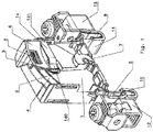
Fig. 1 eine perspektivische Ansicht eines Steckteiles eines Überspannungsableiters ohne Außengehäuse und ohne Unterteil, jedoch mit äußeren elektrischen Schraubanschlussklemmen im funktionsbereiten, das heißt nicht abgetrennten Zustand; -
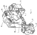
Fig. 2 eine Darstellung ähnlich derjenigen nachFig. 1 , jedoch im abgetrennten Zustand, wobei sich hier der Abtrennbock bereits positionsverlagert hat und in den Zwischenraum zwischen Kontaktstelle und Abtrennstreifen eingetaucht ist; -
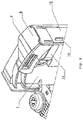
Fig. 3 eine Detailansicht zur Ausbildung der Verbindung eines der Steckkontakte über den Umfang eines zweiten Abtrennstreifenendes, welches in eine schlitzförmige Ausnehmung innerhalb eines zum Tragkörper weisenden Abschnittes des Steckkontaktes eintaucht. - Die Abtrennvorrichtung gemäß dem Ausführungsbeispiel kann Bestandteil eines Überspannungsableiters in Form eines Steckteiles sein, wie dies in der
Figur 1 und2 angedeutet ist. - Das gezeigte Steckteil weist hier noch kein Außengehäuse auf, um den Aufbau und die Funktion der Abtrennvorrichtung deutlich werden zu lassen.
- Das Steckteil besitzt einen Tragkörper 1, der auf einer Seite eine kammerartige Ausnehmung aufweist, die mindestens ein Ableiterelement aufweist.
- Der Tragkörper besitzt einen Durchbruch 2, welcher den Zugang zu einer Kontaktstelle 3 des Ableiterelementes gestattet.
- In diesem Bereich wird die an sich bekannte thermische Trennstelle realisiert.
- Weiterhin weist der Tragkörper 1 eine kurvenförmige Führung 4 zur Aufnahme einer eine Vorspannkraft erzeugenden Feder 5 auf. Weiterhin ist festzuhalten, dass die Feder 5 sich an einem Ende an einem Anschlag eines als Drehschieber ausgebildeten isolierenden Abtrennbockes 6 abstützt.
- Der Drehschieber sitzt auf einer Drehachse 7, die als Fortsatz und damit integrales Element des Tragkörpers 1 ausgeführt sein kann.
- Außenanschlüsse des Überspannungsableiters sind als Steckkontakte 8; 9 ausführbar, die in U-förmige Gegenkontakte 10 und 11 eingreifen.
- Die Gegenkontakte 10 und 11 stehen mit an sich bekannten Außenanschluss-Schraubklemmen 12 und 13 in Verbindung oder sind Bestandteil dieser.
- Erfindungsgemäß ist die Schaltzunge der thermischen Trennstelle als geradflächiger, langgestreckter, metallischer, nachgiebig elastischer Abtrennstreifen 14 ausgebildet.
- Die Verbindung mit der Kontaktfläche 3 des Ableiterelementes erfolgt wie erläutert mittels der thermischen Trennstelle, und zwar über die Breitseite eines ersten Abtrennstreifenendes 140.
- Die Verbindung mit einem der Steckkontakte 9 hingegen erfolgt über den Umfang eines zweiten Abtrennstreifenendes 141, das in eine schlitzförmige Ausnehmung 15 in einem Verlängerungsabschnitt 16 des Steckkontaktes 9 eintaucht.
- Die Ausnehmung 15 entspricht hier im Wesentlichen der Querschnittsfläche des zweiten Abtrennstreifenendes 141 und ist diesem Ende komplementär ausgeführt.
- Eine entsprechende Detaildarstellung ist der
Figur 3 entnehmbar. - Mit dem Erreichen des Schmelzpunktes der thermischen Trennstelle unterliegt der Abtrennbock 6 einer Positionsverlagerung; dies ist in den
Figuren 1 und2 über eine Bewegung nach links nachvollziehbar. - Hierbei hebt der Abtrennstreifen mit seinem ersten Abtrennstreifenende 140 von der Kontaktstelle 3 ab. Weiterhin tritt der Abtrennbock 6 mit seinem Bereich 60 in den sich ergebenden Zwischenraum ein (siehe
Figur 2 ). - Die Positionsverlagerung des Abtrennbockes 6 ist über ein in den Figuren nicht gezeigtes Sichtfenster in einen nicht dargestellten, den Tragkörper 1 umschließenden Außengehäuse erkennbar.
- Diesbezüglich ist am Abtrennbock 6 eine Anzeigefläche 61 angeformt.
- Der Abtrennbock 6 ist, wie aus den
Figuren 1 und2 nachvollziehbar, als Drehschieber ausgebildet. An seiner zur thermischen Trennstelle weisenden Kante 62 kann der Abtrennbock 6 eine Abflachung in Form einer Schrägfläche oder einer Keilfläche besitzen, um das Eindringen in den Trennstellenbereich und den Abtrennvorgang zu optimieren.
Claims (6)
- Überspannungsableiter mit einer Abtrennvorrichtung , welche von einem Tragkörper (1) aufgenommen ist, und sich vom Tragkörper (1) Steckkontakte (8; 9) erstrecken, welche mit mindestens einem Ableiterelement des Überspannungsableiters in Verbindung stehen,
weiterhin mit einer Schaltzunge (14), die an einem ersten Ende (140) über eine thermische Trennstelle mit dem Ableiterelement und mit einem zweiten Ende (141) mit einem der Steckkontakte (9) verbunden ist,
einen am Tragkörper (1) schwenkbar gelagerten unter Federvorspannung stehenden, isolierenden Abtrennbock (6),
wobei die Federvorspannung über die Schaltzunge (14) auf die thermische Trennstelle einwirkt,
weiterhin die Schaltzunge als geradflächiger, langgestreckter, metallischer, nachgiebig elastischer Abtrennstreifen (14) mit rechteckigem Querschnitt ausgebildet ist,
wobei die Verbindung mit einer Kontaktfläche (3) des Ableiterelementes mittels der thermischen Trennstelle über die Breitseite eines ersten Abtrennstreifenendes (140) erfolgt und
mit dem Erreichen des Schmelzpunktes der thermischen Trennstelle der Abtrennbock (6) einer Positionsverlagerung unterliegt und hierbei den Abtrennstreifen (14) mit seinem ersten Abtrennstreifenende (140) von der Kontaktstelle (3) abhebt und der Abtrennbock (6) in den sich ergebenden Zwischenraum eintritt, dadurch gekennzeichnet, dass
die Verbindung der Schaltzunge (14) mit einem der Steckkontakte (9) über den Umfang des zweiten Abtrennstreifenendes (141) erfolgt,
das in eine schlitzförmige Ausnehmung (15) innerhalb eines zum Tragkörper (1) weisenden Abschnittes (16) des Steckkontaktes (9) eintaucht, wobei die Ausnehmung (15) im Wesentlichen der Querschnittsfläche des zweiten Abtrennstreifenendes (141) komplementär ist. - Überspannungsableiter nach Anspruch 1, dadurch gekennzeichnet, dass der Abtrennbock (6) als Drehhebel ausgebildet ist.
- Überspannungsableiter nach Anspruch 1 oder 2, dadurch gekennzeichnet, dass die Positionsverlagerung des Abtrennbockes (6) über ein Sichtfenster in einem den Tragkörper (1) umschließenden Außengehäuse erkennbar ist.
- Überspannungsableiter nach einem der vorangegangenen Ansprüche, dadurch gekennzeichnet, dass am Tragkörper (1) ein Führungsansatz (100) zur Aufnahme des zweiten Abtrennstreifenendes (141) angeformt ist.
- Überspannungsableiter nach einem der vorangegangenen Ansprüche, dadurch gekennzeichnet, dass das zweite Abtrennstreifenende (141) mit dem Steckkontakt (9) verlötet oder verschweißt ist.
- Überspannungsableiter nach einem der vorangegangenen Ansprüche, dadurch gekennzeichnet, dass der Abtrennbock (6) als Drehschieber ausgebildet ist und an seiner zur thermischen Trennstelle weisenden Kante (62) eine Abflachung in Form einer einfachen Schrägfläche oder Keilfläche besitzt.
Priority Applications (2)
| Application Number | Priority Date | Filing Date | Title |
|---|---|---|---|
| PL19725355T PL3673497T3 (pl) | 2018-06-18 | 2019-05-20 | Urządzenie separujące do ogranicznika przepięć |
| SI201930096T SI3673497T1 (sl) | 2018-06-18 | 2019-05-20 | Odklopna naprava za prenapetostni odvodnik |
Applications Claiming Priority (2)
| Application Number | Priority Date | Filing Date | Title |
|---|---|---|---|
| DE102018114564.0A DE102018114564B4 (de) | 2018-06-18 | 2018-06-18 | Überspannungsableiter |
| PCT/EP2019/062906 WO2019242959A1 (de) | 2018-06-18 | 2019-05-20 | Abtrennvorrichtung für einen überspannungsableiter |
Publications (2)
| Publication Number | Publication Date |
|---|---|
| EP3673497A1 EP3673497A1 (de) | 2020-07-01 |
| EP3673497B1 true EP3673497B1 (de) | 2021-07-14 |
Family
ID=66625195
Family Applications (1)
| Application Number | Title | Priority Date | Filing Date |
|---|---|---|---|
| EP19725355.2A Active EP3673497B1 (de) | 2018-06-18 | 2019-05-20 | Abtrennvorrichtung für einen überspannungsableiter |
Country Status (9)
| Country | Link |
|---|---|
| US (1) | US11476071B2 (de) |
| EP (1) | EP3673497B1 (de) |
| JP (1) | JP2021527929A (de) |
| CN (1) | CN112514008B (de) |
| DE (1) | DE102018114564B4 (de) |
| ES (1) | ES2887304T3 (de) |
| PL (1) | PL3673497T3 (de) |
| SI (1) | SI3673497T1 (de) |
| WO (1) | WO2019242959A1 (de) |
Families Citing this family (3)
| Publication number | Priority date | Publication date | Assignee | Title |
|---|---|---|---|---|
| CN214479600U (zh) * | 2021-01-08 | 2021-10-22 | 厦门赛尔特电子有限公司 | 一种石墨浪涌保护器 |
| US20240222962A1 (en) * | 2021-04-30 | 2024-07-04 | SHANGHAI CHENZHU INSTRUMENT Co.,Ltd. | Surge protection module and surge protection device |
| CN115473090B (zh) * | 2022-09-27 | 2025-09-05 | 南京淳科特来电新能源有限公司 | 一种新能源汽车充电设备防过充装置 |
Family Cites Families (24)
| Publication number | Priority date | Publication date | Assignee | Title |
|---|---|---|---|---|
| JPS547389A (en) | 1977-06-17 | 1979-01-20 | Nittan Co Ltd | Photoelectric smoke detector |
| JPS5611335Y2 (de) * | 1977-06-18 | 1981-03-13 | ||
| US6040971A (en) * | 1998-06-08 | 2000-03-21 | Martenson; Kenneth R. | Circuit protection device |
| US6430019B1 (en) * | 1998-06-08 | 2002-08-06 | Ferraz S.A. | Circuit protection device |
| SI1743346T1 (sl) * | 2004-04-19 | 2011-04-29 | Abb France | Zaščitna naprava pred prenapetostjo s sredstvom za prekinitev obloka |
| US7477503B2 (en) * | 2005-04-30 | 2009-01-13 | Efi Electronics Corporation | Circuit protection device |
| US7839257B2 (en) * | 2005-08-05 | 2010-11-23 | Kiwa Spol. S.R.O. | Overvoltage protection with status signalling |
| DE102006036598A1 (de) | 2006-04-26 | 2007-10-31 | Dehn + Söhne Gmbh + Co. Kg | Verfahren zur Dimensionierung einer Abtrennvorrichtung für Überspannungsableiter |
| US7483252B2 (en) * | 2006-12-05 | 2009-01-27 | Ferraz Shawmut S.A. | Circuit protection device |
| DE102007042991B4 (de) * | 2007-06-11 | 2009-09-17 | Dehn + Söhne Gmbh + Co. Kg | Überspannungsschutzgerät mit im thermischen Überlastfall aktivierter mechanischer Abtrennvorrichtung |
| DE102008048644B4 (de) * | 2008-08-01 | 2017-08-24 | DEHN + SÖHNE GmbH + Co. KG. | Überspannungsschutzgerät mit einem oder mehreren parallel geschalteten, in einer baulichen Einheit befindlichen überspannungsbegrenzenden Elementen |
| US8031456B2 (en) * | 2009-05-12 | 2011-10-04 | Ceramate Technical Co., Ltd. | Explosion-roof and flameproof pullout safety surge absorbing module |
| US8836464B2 (en) * | 2009-06-24 | 2014-09-16 | Ceramate Technical Co., Ltd. | Explosion-proof and flameproof ejection type safety surge-absorbing module |
| FR2958788B1 (fr) * | 2010-04-09 | 2015-01-30 | Abb France | Varistance comprenant une electrode avec une partie en saillie formant pole et parafoudre comprenant une telle varistance |
| US8502637B2 (en) * | 2010-09-22 | 2013-08-06 | Thomas & Betts International, Inc. | Surge protective device with thermal decoupler and arc suppression |
| DE102011018556A1 (de) * | 2011-02-18 | 2012-08-23 | Dehn + Söhne Gmbh + Co. Kg | Überspannungsschutzeinrichtung, umfassend mindestens einen Überspannungsableiter |
| US9165702B2 (en) * | 2011-03-07 | 2015-10-20 | James P. Hagerty | Thermally-protected varistor |
| JP5981537B2 (ja) * | 2011-06-17 | 2016-08-31 | リッテルフューズ,インコーポレイティド | 熱金属酸化物バリスタ回路保護デバイス |
| DE102013006052B4 (de) * | 2013-02-08 | 2016-08-04 | DEHN + SÖHNE GmbH + Co. KG. | Überspannungsschutzgerät |
| DE102013022348B4 (de) | 2013-10-22 | 2016-01-07 | Dehn + Söhne Gmbh + Co. Kg | Überspannungsschutzeinrichtung, aufweisend mindestens einen Überspannungsableiter und eine, mit dem Überspannungsableiter in Reihe geschaltete, thermisch auslösbare Schalteinrichtung |
| DE202014002496U1 (de) * | 2014-03-20 | 2014-04-17 | Dehn + Söhne Gmbh + Co. Kg | Überspannungsschutzeinrichtung, umfassend mindestens einen Überspannungsableiter und eine dem Überspannungsableiter parallel geschaltete, thermisch auslösbare, federvorgespannte Kurzschliessschalteinrichtung |
| DE202014103262U1 (de) | 2014-07-15 | 2014-07-30 | Phoenix Contact Gmbh & Co. Kg | Überspannungsschutzelement |
| CN204131121U (zh) * | 2014-11-10 | 2015-01-28 | 毛小毛 | 具有高结构稳定性的电涌抑制装置 |
| DE202016107504U1 (de) | 2016-06-22 | 2017-03-02 | Dehn + Söhne Gmbh + Co. Kg | Überspannungsschutzanordnung mit mindestens einem, auf einer ersten Seite einer n-eckigen Trägerplatte angeordneten, scheibenförmigen Varistor |
-
2018
- 2018-06-18 DE DE102018114564.0A patent/DE102018114564B4/de active Active
-
2019
- 2019-05-20 WO PCT/EP2019/062906 patent/WO2019242959A1/de not_active Ceased
- 2019-05-20 CN CN201980048162.3A patent/CN112514008B/zh active Active
- 2019-05-20 JP JP2020570528A patent/JP2021527929A/ja active Pending
- 2019-05-20 ES ES19725355T patent/ES2887304T3/es active Active
- 2019-05-20 PL PL19725355T patent/PL3673497T3/pl unknown
- 2019-05-20 EP EP19725355.2A patent/EP3673497B1/de active Active
- 2019-05-20 SI SI201930096T patent/SI3673497T1/sl unknown
- 2019-05-20 US US17/251,895 patent/US11476071B2/en active Active
Non-Patent Citations (1)
| Title |
|---|
| None * |
Also Published As
| Publication number | Publication date |
|---|---|
| DE102018114564A1 (de) | 2019-12-19 |
| CN112514008A (zh) | 2021-03-16 |
| JP2021527929A (ja) | 2021-10-14 |
| DE102018114564B4 (de) | 2023-01-19 |
| SI3673497T1 (sl) | 2021-11-30 |
| US20210125804A1 (en) | 2021-04-29 |
| ES2887304T3 (es) | 2021-12-22 |
| PL3673497T3 (pl) | 2021-12-06 |
| WO2019242959A1 (de) | 2019-12-26 |
| US11476071B2 (en) | 2022-10-18 |
| CN112514008B (zh) | 2022-07-19 |
| EP3673497A1 (de) | 2020-07-01 |
Similar Documents
| Publication | Publication Date | Title |
|---|---|---|
| DE69606706T2 (de) | Elektrische anschlussklemme | |
| DE19941190B4 (de) | Wärmeschutzsicherung | |
| DE69515128T2 (de) | Anschlussklemme auf sammelschienen für lastschalter oder mehrpolige trennbare systeme | |
| EP3673497B1 (de) | Abtrennvorrichtung für einen überspannungsableiter | |
| EP2011128A1 (de) | Verfahren zur dimensionierung einer abtrennvorrichtung für überspannungsableiter | |
| DE102008029670B4 (de) | Überspannungsschutzelement | |
| DE202014103262U1 (de) | Überspannungsschutzelement | |
| DE102008031917A1 (de) | Überspannungschutzelement | |
| DE102013022348B4 (de) | Überspannungsschutzeinrichtung, aufweisend mindestens einen Überspannungsableiter und eine, mit dem Überspannungsableiter in Reihe geschaltete, thermisch auslösbare Schalteinrichtung | |
| EP1291979B1 (de) | Elektrisches Anschlusselement | |
| DE102018215879B4 (de) | Steckverbindung mit Redundanz sowie Fahrzeug mit einer solchen | |
| DE102017124224B4 (de) | Überspannungsschutzgerät | |
| DE102014003113B3 (de) | Steckverbindungsteil mit Klammerelementen | |
| DE1181299B (de) | Elektrothermische Schaltvorrichtung | |
| DE102022119929B4 (de) | Schnappschalter | |
| DE102019106960B4 (de) | Elektronisches Bauteil | |
| DE102019112680B4 (de) | Überspannungsschutzgerät | |
| EP1360709A1 (de) | Schaltkontaktanordnung | |
| DE102015103113B4 (de) | Trennklemme mit konkavem Trennmesser | |
| DE202018006119U1 (de) | Abtrennvorrichtung für einen Überspannungsableiter | |
| AT502415B1 (de) | Prüftaster, anschlussverbindung für einen prüftaster, schutzschalter und verfahren zur herstellung eines schutzschalters | |
| DE102006043795B3 (de) | Elektrischer Mikroschalter | |
| DE102017112429B4 (de) | Überspannungsschutzelement | |
| DE102023131721B3 (de) | Schnappschalter | |
| EP0406533A1 (de) | Klemmverbinder |
Legal Events
| Date | Code | Title | Description |
|---|---|---|---|
| STAA | Information on the status of an ep patent application or granted ep patent |
Free format text: STATUS: UNKNOWN |
|
| STAA | Information on the status of an ep patent application or granted ep patent |
Free format text: STATUS: THE INTERNATIONAL PUBLICATION HAS BEEN MADE |
|
| PUAI | Public reference made under article 153(3) epc to a published international application that has entered the european phase |
Free format text: ORIGINAL CODE: 0009012 |
|
| STAA | Information on the status of an ep patent application or granted ep patent |
Free format text: STATUS: REQUEST FOR EXAMINATION WAS MADE |
|
| 17P | Request for examination filed |
Effective date: 20200325 |
|
| AK | Designated contracting states |
Kind code of ref document: A1 Designated state(s): AL AT BE BG CH CY CZ DE DK EE ES FI FR GB GR HR HU IE IS IT LI LT LU LV MC MK MT NL NO PL PT RO RS SE SI SK SM TR |
|
| AX | Request for extension of the european patent |
Extension state: BA ME |
|
| STAA | Information on the status of an ep patent application or granted ep patent |
Free format text: STATUS: EXAMINATION IS IN PROGRESS |
|
| 17Q | First examination report despatched |
Effective date: 20200714 |
|
| GRAP | Despatch of communication of intention to grant a patent |
Free format text: ORIGINAL CODE: EPIDOSNIGR1 |
|
| STAA | Information on the status of an ep patent application or granted ep patent |
Free format text: STATUS: GRANT OF PATENT IS INTENDED |
|
| DAV | Request for validation of the european patent (deleted) | ||
| DAX | Request for extension of the european patent (deleted) | ||
| INTG | Intention to grant announced |
Effective date: 20210205 |
|
| GRAS | Grant fee paid |
Free format text: ORIGINAL CODE: EPIDOSNIGR3 |
|
| GRAA | (expected) grant |
Free format text: ORIGINAL CODE: 0009210 |
|
| STAA | Information on the status of an ep patent application or granted ep patent |
Free format text: STATUS: THE PATENT HAS BEEN GRANTED |
|
| AK | Designated contracting states |
Kind code of ref document: B1 Designated state(s): AL AT BE BG CH CY CZ DE DK EE ES FI FR GB GR HR HU IE IS IT LI LT LU LV MC MK MT NL NO PL PT RO RS SE SI SK SM TR |
|
| REG | Reference to a national code |
Ref country code: GB Ref legal event code: FG4D Free format text: NOT ENGLISH |
|
| REG | Reference to a national code |
Ref country code: IE Ref legal event code: FG4D Free format text: LANGUAGE OF EP DOCUMENT: GERMAN |
|
| REG | Reference to a national code |
Ref country code: DE Ref legal event code: R096 Ref document number: 502019001819 Country of ref document: DE |
|
| REG | Reference to a national code |
Ref country code: AT Ref legal event code: REF Ref document number: 1411299 Country of ref document: AT Kind code of ref document: T Effective date: 20210815 |
|
| REG | Reference to a national code |
Ref country code: LT Ref legal event code: MG9D |
|
| REG | Reference to a national code |
Ref country code: NL Ref legal event code: MP Effective date: 20210714 |
|
| REG | Reference to a national code |
Ref country code: ES Ref legal event code: FG2A Ref document number: 2887304 Country of ref document: ES Kind code of ref document: T3 Effective date: 20211222 |
|
| PG25 | Lapsed in a contracting state [announced via postgrant information from national office to epo] |
Ref country code: SE Free format text: LAPSE BECAUSE OF FAILURE TO SUBMIT A TRANSLATION OF THE DESCRIPTION OR TO PAY THE FEE WITHIN THE PRESCRIBED TIME-LIMIT Effective date: 20210714 Ref country code: RS Free format text: LAPSE BECAUSE OF FAILURE TO SUBMIT A TRANSLATION OF THE DESCRIPTION OR TO PAY THE FEE WITHIN THE PRESCRIBED TIME-LIMIT Effective date: 20210714 Ref country code: BG Free format text: LAPSE BECAUSE OF FAILURE TO SUBMIT A TRANSLATION OF THE DESCRIPTION OR TO PAY THE FEE WITHIN THE PRESCRIBED TIME-LIMIT Effective date: 20211014 Ref country code: LT Free format text: LAPSE BECAUSE OF FAILURE TO SUBMIT A TRANSLATION OF THE DESCRIPTION OR TO PAY THE FEE WITHIN THE PRESCRIBED TIME-LIMIT Effective date: 20210714 Ref country code: HR Free format text: LAPSE BECAUSE OF FAILURE TO SUBMIT A TRANSLATION OF THE DESCRIPTION OR TO PAY THE FEE WITHIN THE PRESCRIBED TIME-LIMIT Effective date: 20210714 Ref country code: FI Free format text: LAPSE BECAUSE OF FAILURE TO SUBMIT A TRANSLATION OF THE DESCRIPTION OR TO PAY THE FEE WITHIN THE PRESCRIBED TIME-LIMIT Effective date: 20210714 Ref country code: PT Free format text: LAPSE BECAUSE OF FAILURE TO SUBMIT A TRANSLATION OF THE DESCRIPTION OR TO PAY THE FEE WITHIN THE PRESCRIBED TIME-LIMIT Effective date: 20211115 Ref country code: NL Free format text: LAPSE BECAUSE OF FAILURE TO SUBMIT A TRANSLATION OF THE DESCRIPTION OR TO PAY THE FEE WITHIN THE PRESCRIBED TIME-LIMIT Effective date: 20210714 Ref country code: NO Free format text: LAPSE BECAUSE OF FAILURE TO SUBMIT A TRANSLATION OF THE DESCRIPTION OR TO PAY THE FEE WITHIN THE PRESCRIBED TIME-LIMIT Effective date: 20211014 |
|
| REG | Reference to a national code |
Ref country code: DE Ref legal event code: R081 Ref document number: 502019001819 Country of ref document: DE Owner name: DEHN SE, DE Free format text: FORMER OWNER: DEHN SE + CO KG, 92318 NEUMARKT, DE |
|
| PG25 | Lapsed in a contracting state [announced via postgrant information from national office to epo] |
Ref country code: LV Free format text: LAPSE BECAUSE OF FAILURE TO SUBMIT A TRANSLATION OF THE DESCRIPTION OR TO PAY THE FEE WITHIN THE PRESCRIBED TIME-LIMIT Effective date: 20210714 Ref country code: GR Free format text: LAPSE BECAUSE OF FAILURE TO SUBMIT A TRANSLATION OF THE DESCRIPTION OR TO PAY THE FEE WITHIN THE PRESCRIBED TIME-LIMIT Effective date: 20211015 |
|
| REG | Reference to a national code |
Ref country code: DE Ref legal event code: R097 Ref document number: 502019001819 Country of ref document: DE |
|
| RAP2 | Party data changed (patent owner data changed or rights of a patent transferred) |
Owner name: DEHN SE |
|
| PG25 | Lapsed in a contracting state [announced via postgrant information from national office to epo] |
Ref country code: DK Free format text: LAPSE BECAUSE OF FAILURE TO SUBMIT A TRANSLATION OF THE DESCRIPTION OR TO PAY THE FEE WITHIN THE PRESCRIBED TIME-LIMIT Effective date: 20210714 |
|
| PLBE | No opposition filed within time limit |
Free format text: ORIGINAL CODE: 0009261 |
|
| STAA | Information on the status of an ep patent application or granted ep patent |
Free format text: STATUS: NO OPPOSITION FILED WITHIN TIME LIMIT |
|
| PG25 | Lapsed in a contracting state [announced via postgrant information from national office to epo] |
Ref country code: SM Free format text: LAPSE BECAUSE OF FAILURE TO SUBMIT A TRANSLATION OF THE DESCRIPTION OR TO PAY THE FEE WITHIN THE PRESCRIBED TIME-LIMIT Effective date: 20210714 Ref country code: SK Free format text: LAPSE BECAUSE OF FAILURE TO SUBMIT A TRANSLATION OF THE DESCRIPTION OR TO PAY THE FEE WITHIN THE PRESCRIBED TIME-LIMIT Effective date: 20210714 Ref country code: RO Free format text: LAPSE BECAUSE OF FAILURE TO SUBMIT A TRANSLATION OF THE DESCRIPTION OR TO PAY THE FEE WITHIN THE PRESCRIBED TIME-LIMIT Effective date: 20210714 Ref country code: EE Free format text: LAPSE BECAUSE OF FAILURE TO SUBMIT A TRANSLATION OF THE DESCRIPTION OR TO PAY THE FEE WITHIN THE PRESCRIBED TIME-LIMIT Effective date: 20210714 Ref country code: CZ Free format text: LAPSE BECAUSE OF FAILURE TO SUBMIT A TRANSLATION OF THE DESCRIPTION OR TO PAY THE FEE WITHIN THE PRESCRIBED TIME-LIMIT Effective date: 20210714 Ref country code: AL Free format text: LAPSE BECAUSE OF FAILURE TO SUBMIT A TRANSLATION OF THE DESCRIPTION OR TO PAY THE FEE WITHIN THE PRESCRIBED TIME-LIMIT Effective date: 20210714 |
|
| 26N | No opposition filed |
Effective date: 20220419 |
|
| REG | Reference to a national code |
Ref country code: CH Ref legal event code: PL |
|
| REG | Reference to a national code |
Ref country code: BE Ref legal event code: MM Effective date: 20220531 |
|
| PG25 | Lapsed in a contracting state [announced via postgrant information from national office to epo] |
Ref country code: MC Free format text: LAPSE BECAUSE OF FAILURE TO SUBMIT A TRANSLATION OF THE DESCRIPTION OR TO PAY THE FEE WITHIN THE PRESCRIBED TIME-LIMIT Effective date: 20210714 Ref country code: LU Free format text: LAPSE BECAUSE OF NON-PAYMENT OF DUE FEES Effective date: 20220520 Ref country code: CH Free format text: LAPSE BECAUSE OF NON-PAYMENT OF DUE FEES Effective date: 20220531 Ref country code: LI Free format text: LAPSE BECAUSE OF NON-PAYMENT OF DUE FEES Effective date: 20220531 |
|
| PG25 | Lapsed in a contracting state [announced via postgrant information from national office to epo] |
Ref country code: SI Free format text: LAPSE BECAUSE OF NON-PAYMENT OF DUE FEES Effective date: 20220521 |
|
| PG25 | Lapsed in a contracting state [announced via postgrant information from national office to epo] |
Ref country code: IE Free format text: LAPSE BECAUSE OF NON-PAYMENT OF DUE FEES Effective date: 20220520 |
|
| PG25 | Lapsed in a contracting state [announced via postgrant information from national office to epo] |
Ref country code: BE Free format text: LAPSE BECAUSE OF NON-PAYMENT OF DUE FEES Effective date: 20220531 |
|
| REG | Reference to a national code |
Ref country code: ES Ref legal event code: FD2A Effective date: 20230626 |
|
| PG25 | Lapsed in a contracting state [announced via postgrant information from national office to epo] |
Ref country code: ES Free format text: LAPSE BECAUSE OF NON-PAYMENT OF DUE FEES Effective date: 20220521 |
|
| REG | Reference to a national code |
Ref country code: AT Ref legal event code: PC Ref document number: 1411299 Country of ref document: AT Kind code of ref document: T Owner name: DEHN SE, DE Effective date: 20230822 |
|
| GBPC | Gb: european patent ceased through non-payment of renewal fee |
Effective date: 20230520 |
|
| PG25 | Lapsed in a contracting state [announced via postgrant information from national office to epo] |
Ref country code: MK Free format text: LAPSE BECAUSE OF FAILURE TO SUBMIT A TRANSLATION OF THE DESCRIPTION OR TO PAY THE FEE WITHIN THE PRESCRIBED TIME-LIMIT Effective date: 20210714 Ref country code: CY Free format text: LAPSE BECAUSE OF FAILURE TO SUBMIT A TRANSLATION OF THE DESCRIPTION OR TO PAY THE FEE WITHIN THE PRESCRIBED TIME-LIMIT Effective date: 20210714 Ref country code: GB Free format text: LAPSE BECAUSE OF NON-PAYMENT OF DUE FEES Effective date: 20230520 |
|
| PG25 | Lapsed in a contracting state [announced via postgrant information from national office to epo] |
Ref country code: PL Free format text: LAPSE BECAUSE OF NON-PAYMENT OF DUE FEES Effective date: 20220520 Ref country code: HU Free format text: LAPSE BECAUSE OF FAILURE TO SUBMIT A TRANSLATION OF THE DESCRIPTION OR TO PAY THE FEE WITHIN THE PRESCRIBED TIME-LIMIT; INVALID AB INITIO Effective date: 20190520 |
|
| PG25 | Lapsed in a contracting state [announced via postgrant information from national office to epo] |
Ref country code: TR Free format text: LAPSE BECAUSE OF FAILURE TO SUBMIT A TRANSLATION OF THE DESCRIPTION OR TO PAY THE FEE WITHIN THE PRESCRIBED TIME-LIMIT Effective date: 20210714 |
|
| PG25 | Lapsed in a contracting state [announced via postgrant information from national office to epo] |
Ref country code: MT Free format text: LAPSE BECAUSE OF FAILURE TO SUBMIT A TRANSLATION OF THE DESCRIPTION OR TO PAY THE FEE WITHIN THE PRESCRIBED TIME-LIMIT Effective date: 20210714 |
|
| PGFP | Annual fee paid to national office [announced via postgrant information from national office to epo] |
Ref country code: DE Payment date: 20250519 Year of fee payment: 7 |
|
| PGFP | Annual fee paid to national office [announced via postgrant information from national office to epo] |
Ref country code: IT Payment date: 20250530 Year of fee payment: 7 |
|
| PGFP | Annual fee paid to national office [announced via postgrant information from national office to epo] |
Ref country code: FR Payment date: 20250523 Year of fee payment: 7 |
|
| PGFP | Annual fee paid to national office [announced via postgrant information from national office to epo] |
Ref country code: AT Payment date: 20250519 Year of fee payment: 7 |