EP2007990B1 - Procédé de fabrication d'une vis autotaraudeuse de haute performance - Google Patents
Procédé de fabrication d'une vis autotaraudeuse de haute performance Download PDFInfo
- Publication number
- EP2007990B1 EP2007990B1 EP07759995.9A EP07759995A EP2007990B1 EP 2007990 B1 EP2007990 B1 EP 2007990B1 EP 07759995 A EP07759995 A EP 07759995A EP 2007990 B1 EP2007990 B1 EP 2007990B1
- Authority
- EP
- European Patent Office
- Prior art keywords
- screw
- threads
- forming
- tempering
- carbon
- Prior art date
- Legal status (The legal status is an assumption and is not a legal conclusion. Google has not performed a legal analysis and makes no representation as to the accuracy of the status listed.)
- Active
Links
- 238000000034 method Methods 0.000 title claims description 42
- OKTJSMMVPCPJKN-UHFFFAOYSA-N Carbon Chemical compound [C] OKTJSMMVPCPJKN-UHFFFAOYSA-N 0.000 claims description 25
- 229910052799 carbon Inorganic materials 0.000 claims description 25
- 238000005496 tempering Methods 0.000 claims description 20
- 230000006698 induction Effects 0.000 claims description 19
- 238000010791 quenching Methods 0.000 claims description 13
- 230000000171 quenching effect Effects 0.000 claims description 11
- 229910000831 Steel Inorganic materials 0.000 claims description 7
- 239000010959 steel Substances 0.000 claims description 7
- 239000003921 oil Substances 0.000 claims description 3
- 229910000851 Alloy steel Inorganic materials 0.000 claims description 2
- PWHULOQIROXLJO-UHFFFAOYSA-N Manganese Chemical compound [Mn] PWHULOQIROXLJO-UHFFFAOYSA-N 0.000 claims description 2
- ZOKXTWBITQBERF-UHFFFAOYSA-N Molybdenum Chemical compound [Mo] ZOKXTWBITQBERF-UHFFFAOYSA-N 0.000 claims description 2
- XUIMIQQOPSSXEZ-UHFFFAOYSA-N Silicon Chemical compound [Si] XUIMIQQOPSSXEZ-UHFFFAOYSA-N 0.000 claims description 2
- NINIDFKCEFEMDL-UHFFFAOYSA-N Sulfur Chemical compound [S] NINIDFKCEFEMDL-UHFFFAOYSA-N 0.000 claims description 2
- 239000005864 Sulphur Substances 0.000 claims description 2
- 230000005684 electric field Effects 0.000 claims description 2
- BHEPBYXIRTUNPN-UHFFFAOYSA-N hydridophosphorus(.) (triplet) Chemical compound [PH] BHEPBYXIRTUNPN-UHFFFAOYSA-N 0.000 claims description 2
- 229910052748 manganese Inorganic materials 0.000 claims description 2
- 239000011572 manganese Substances 0.000 claims description 2
- 239000000203 mixture Substances 0.000 claims description 2
- 229910052750 molybdenum Inorganic materials 0.000 claims description 2
- 239000011733 molybdenum Substances 0.000 claims description 2
- 229910052710 silicon Inorganic materials 0.000 claims description 2
- 239000010703 silicon Substances 0.000 claims description 2
- 239000000463 material Substances 0.000 description 20
- 229910045601 alloy Inorganic materials 0.000 description 2
- 239000000956 alloy Substances 0.000 description 2
- 238000004519 manufacturing process Methods 0.000 description 2
- 230000013011 mating Effects 0.000 description 2
- XLYOFNOQVPJJNP-UHFFFAOYSA-N water Substances O XLYOFNOQVPJJNP-UHFFFAOYSA-N 0.000 description 2
- 229910000760 Hardened steel Inorganic materials 0.000 description 1
- 238000005260 corrosion Methods 0.000 description 1
- 230000007797 corrosion Effects 0.000 description 1
- 238000010586 diagram Methods 0.000 description 1
- 238000012986 modification Methods 0.000 description 1
- 230000004048 modification Effects 0.000 description 1
- 238000005121 nitriding Methods 0.000 description 1
- 230000008520 organization Effects 0.000 description 1
- 238000004080 punching Methods 0.000 description 1
- 239000007921 spray Substances 0.000 description 1
Images
Classifications
-
- F—MECHANICAL ENGINEERING; LIGHTING; HEATING; WEAPONS; BLASTING
- F16—ENGINEERING ELEMENTS AND UNITS; GENERAL MEASURES FOR PRODUCING AND MAINTAINING EFFECTIVE FUNCTIONING OF MACHINES OR INSTALLATIONS; THERMAL INSULATION IN GENERAL
- F16B—DEVICES FOR FASTENING OR SECURING CONSTRUCTIONAL ELEMENTS OR MACHINE PARTS TOGETHER, e.g. NAILS, BOLTS, CIRCLIPS, CLAMPS, CLIPS OR WEDGES; JOINTS OR JOINTING
- F16B25/00—Screws that cut thread in the body into which they are screwed, e.g. wood screws
-
- B—PERFORMING OPERATIONS; TRANSPORTING
- B21—MECHANICAL METAL-WORKING WITHOUT ESSENTIALLY REMOVING MATERIAL; PUNCHING METAL
- B21K—MAKING FORGED OR PRESSED METAL PRODUCTS, e.g. HORSE-SHOES, RIVETS, BOLTS OR WHEELS
- B21K1/00—Making machine elements
- B21K1/44—Making machine elements bolts, studs, or the like
- B21K1/46—Making machine elements bolts, studs, or the like with heads
-
- B—PERFORMING OPERATIONS; TRANSPORTING
- B21—MECHANICAL METAL-WORKING WITHOUT ESSENTIALLY REMOVING MATERIAL; PUNCHING METAL
- B21K—MAKING FORGED OR PRESSED METAL PRODUCTS, e.g. HORSE-SHOES, RIVETS, BOLTS OR WHEELS
- B21K1/00—Making machine elements
- B21K1/56—Making machine elements screw-threaded elements
-
- C—CHEMISTRY; METALLURGY
- C21—METALLURGY OF IRON
- C21D—MODIFYING THE PHYSICAL STRUCTURE OF FERROUS METALS; GENERAL DEVICES FOR HEAT TREATMENT OF FERROUS OR NON-FERROUS METALS OR ALLOYS; MAKING METAL MALLEABLE, e.g. BY DECARBURISATION OR TEMPERING
- C21D9/00—Heat treatment, e.g. annealing, hardening, quenching or tempering, adapted for particular articles; Furnaces therefor
- C21D9/0093—Heat treatment, e.g. annealing, hardening, quenching or tempering, adapted for particular articles; Furnaces therefor for screws; for bolts
-
- F—MECHANICAL ENGINEERING; LIGHTING; HEATING; WEAPONS; BLASTING
- F16—ENGINEERING ELEMENTS AND UNITS; GENERAL MEASURES FOR PRODUCING AND MAINTAINING EFFECTIVE FUNCTIONING OF MACHINES OR INSTALLATIONS; THERMAL INSULATION IN GENERAL
- F16B—DEVICES FOR FASTENING OR SECURING CONSTRUCTIONAL ELEMENTS OR MACHINE PARTS TOGETHER, e.g. NAILS, BOLTS, CIRCLIPS, CLAMPS, CLIPS OR WEDGES; JOINTS OR JOINTING
- F16B25/00—Screws that cut thread in the body into which they are screwed, e.g. wood screws
- F16B25/001—Screws that cut thread in the body into which they are screwed, e.g. wood screws characterised by the material of the body into which the screw is screwed
- F16B25/0021—Screws that cut thread in the body into which they are screwed, e.g. wood screws characterised by the material of the body into which the screw is screwed the material being metal, e.g. sheet-metal or aluminium
-
- F—MECHANICAL ENGINEERING; LIGHTING; HEATING; WEAPONS; BLASTING
- F16—ENGINEERING ELEMENTS AND UNITS; GENERAL MEASURES FOR PRODUCING AND MAINTAINING EFFECTIVE FUNCTIONING OF MACHINES OR INSTALLATIONS; THERMAL INSULATION IN GENERAL
- F16B—DEVICES FOR FASTENING OR SECURING CONSTRUCTIONAL ELEMENTS OR MACHINE PARTS TOGETHER, e.g. NAILS, BOLTS, CIRCLIPS, CLAMPS, CLIPS OR WEDGES; JOINTS OR JOINTING
- F16B33/00—Features common to bolt and nut
- F16B33/06—Surface treatment of parts furnished with screw-thread, e.g. for preventing seizure or fretting
-
- Y—GENERAL TAGGING OF NEW TECHNOLOGICAL DEVELOPMENTS; GENERAL TAGGING OF CROSS-SECTIONAL TECHNOLOGIES SPANNING OVER SEVERAL SECTIONS OF THE IPC; TECHNICAL SUBJECTS COVERED BY FORMER USPC CROSS-REFERENCE ART COLLECTIONS [XRACs] AND DIGESTS
- Y02—TECHNOLOGIES OR APPLICATIONS FOR MITIGATION OR ADAPTATION AGAINST CLIMATE CHANGE
- Y02P—CLIMATE CHANGE MITIGATION TECHNOLOGIES IN THE PRODUCTION OR PROCESSING OF GOODS
- Y02P10/00—Technologies related to metal processing
- Y02P10/25—Process efficiency
Definitions
- the present invention generally relates to thread forming screws and methods of forming same, and more specifically relates to a fastener, such as a thread forming screw, at least a portion of which has a minimum surface hardness of HRC 56 (Rockwell Hardness C-scale), and to a method of forming such a thread forming screw as disclosed in US 3, 935, 785 A .
- a fastener such as a thread forming screw, at least a portion of which has a minimum surface hardness of HRC 56 (Rockwell Hardness C-scale)
- HRC 56 Rockwell Hardness C-scale
- Conventional thread forming screws are not hard enough to successfully cold form threads into workpieces which exceed a Rockwell C23 hardness.
- some commercially available thread forming screws are processed so that the point and the first three to four full threads are at a Rockwell C45 minimum hardness, and the core of the fastener is at Rockwell C33 to 39 hardness.
- a thread forming screw such as this is not hard enough to consistently cold form threads into a material which exceeds HRC 23.
- HSLA material or any other material having a hardness of HRC 40 or more
- thread collapse occurs. This collapse, or deformation of the threads, causes joint failure.
- EP1054170 discloses a high strength screw in which a high strength steel material is employed and hardened by the administering of a carburization hardening process, to try to improve the ability to withstand high tensile and sheer stress loads.
- DE10113946A1 Toge-Duebel ) discloses a self-threading screw made from hardened steel, hardened using a method, which aims to reduce its resistance to corrosion and reduce its manufacturing cost.
- fasteners capable of forming threads in workpieces, such as HSLA material or any other material, which has a hardness which exceeds Rockwell C23.
- An object of the present invention is to provide a thread forming screw at least a portion of which has a surface hardness that is sufficiently high such that the thread forming screw can be used to cold form threads in a workpiece which has a hardness that exceeds HRC 23.
- Another object of the present invention is to provide a thread forming screw at least a portion of which has a minimum surface hardness of HRC 56.
- Still another object of the present invention is to provide a thread forming screw which has a minimum surface hardness of HRC 56, preferably to at least a depth of 0.008 inches (0.2 millimetres), for at least some of the threads of the screw.
- a method for forming a thread forming screw which is configured to cold form threads in a workpiece having a surface hardness which exceeds HRC 23, said method comprising the steps of providing a wire made of steel; drawing the wire at a cold heading machine to form a head and a shank extending from the head to a free end; forming threads on the shank to form a screw, wherein the formed threads comprise full threads proximate to the head and lead threads between the full threads and the free end; said method being characterized by performing a heat treating process on the screw, by first carbon enriching, quenching and tempering the screw to provide that a surface hardness and a core hardness of the screw is at a Rockwell C33 to 39 hardness and to provide that a surface hardness of the screw does not exceed a core hardness of the screw by more than 3 Rockwell C points, and by second induction hardening the lead threads and at least three of the full threads of the screw that are provided closest
- the present invention provides a method of forming a thread forming screw which has a head and a threaded shank extending from the head. At least some of the threads of the shank are surface hardened, to a minimum surface hardness of HRC 56, thereby enabling the thread forming screw to thereafter be used to cold form threads in a workpiece having a surface hardness which exceeds HRC 23.
- the method includes performing a heat treating process whereby the screw is carbon enriched preferably to at least a 0.48 carbon level, and is quenched, such as in oil.
- the screw can then be tempered in order to lower the brittleness and to allow for a more ductile core.
- the tempering is controlled such that the surface hardness does not exceed the core hardness by more than 3 Rockwell C points.
- both the surface and core of the fastener are at a Rockwell C33 to 39 hardness.
- the point such as the lead threads and three to four full threads of the screw, is induction hardened and the screw can be quenched, such as in water or in a synthetic quench.
- the screw is then tempered again to a lower brittleness.
- this tempering step is controlled such that the lead threads and the first three to four full threads are at a Rockwell C56 minimum hardness, preferably to a depth of at least 0.008 inches (0.2 millimetres), and the core of the fastener is at Rockwell C33 to 39 hardness.
- a finish is applied to the fastener.
- One aspect of the present invention relates to a fastener, such as a thread forming screw, at least a portion of which has a surface hardness of HRC 56.
- Another aspect relates to a method of surface hardening a fastener, such as a thread forming screw, such that at least a portion of which has a surface hardness of HRC 56. While the method can be used in connection with a wide range of screws, U.S. Patent No. 3,935,785 discloses a screw with which a method in accordance with an embodiment of the present invention can be used.
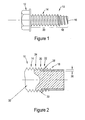
- the screw 10 includes a head 12 and a threaded shank 14 which extends from the head 12.
- a plurality of lead threads 18 which taper somewhat to the point 16 of the screw 10.
- reference numeral 22 identifies the first full thread
- reference numeral 24 identifies the fourth full thread. More detail regarding the shape and function of this particular screw can be found in the '785 patent.
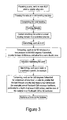
- an example of a preferred, specific embodiment of the present invention provides as shown in Figure 2 , wherein the lead threads 18 as well as the first three or four full threads of the screw, are surface hardened to a Rockwell hardness of at least HRC 56, to a depth (i.e., dimension 26 identified in Figure 2 ) of at least 0.008 inches (0.2 millimetres).
- the core of the screw 10 is at Rockwell C33 to 39 hardness, such that the screw 10 has a relatively ductile core.
- the portion identified with reference numeral 28 has a minimum induction hardened area at HRC 56 min.
- the portion identified with reference numeral 30 has a maximum induction hardened area at HRC 56 min.
- the portion identified with reference numeral 32 is a hardened, quenched, and tempered area, having a surface hardness within 3 points HRC of the core.
- Figure 3 illustrates a method which is in accordance with an embodiment of the present invention, and the method can be used to form a thread forming screw 10 such as shown in Figures 1 and 2 .
- the method provides that, for example, a wire made of steel 4037 steel or a similar alloy is provided, and the wire is drawn at a cold heading machine.
- the material may be an alloy steel, AISI C4037 grade analysis with a composition of: carbon 0.35-0.40 percent; manganese 0.70-0.90 percent, sulphur 0.040 percent max., phosphorous 0.035 percent max., silicon 0.20-0.35 percent and molybdenum 0.20-0.30 percent, normally specified as killed, fine grain, spherodized annealed steel.
- the screw is carbon enriched using a controlled process, in a quality furnace, such that the screw obtains at least a 0.48 carbon level.
- the carbon enrichment allows the surface of the fastener to be hardened harder than the base material.
- the screw can be left in the furnace for 90 minutes while the furnace is at 1600-1700 degrees Fahrenheit (871-927 degrees Centrigrade).
- the furnace atmosphere is preferably controlled to 0.6 to 0.7% carbon potential (with no nitriding).
- the depth (i.e., dimension 26 in Figure 2 ) of the carbon restored zone is at least 0.008 inches (0.2 millimetres).
- the surface hardness after tempering does not exceed the core hardness by more than 3 Rockwell C (30 Vickers) points equivalent.
- a 1 to 2 Rockwell C (10-20 Vickers) equivalent surface hardness increase would be an objective in selecting furnace parameters.
- a microhardness tester can be employed to measure the hardness and depth of the carbon restored zone, in order to help set the furnace parameters.
- the screw is quenched, such as in oil at 140-160 degrees Fahrenheit (60-71 degrees Centrigrade).
- the screw is tempered, such as for 90 minutes at a temperature of 850-950 degrees Fahrenheit (454-510 degrees Centrigrade), in order to lower the brittleness and allow for a more ductile core in the fastener.
- this step is controlled such that the surface hardness does not exceed the core hardness by more than 3 Rockwell C points.
- both the surface and the core of the fastener are at a Rockwell C33 to 39 hardness.
- the point of the screw such as the lead threads 18 and the first three to four full threads, is induction hardened, wherein the lead threads of the fastener are momentarily fed into the influence of an electric field in such a way as to induction heat the threads to the hardening temperature (approximately 1650-1750 degrees Fahrenheit (899-954 degrees Centrigrade)).
- the screw is thereafter immediately quenched, such as in water spray or viz-a-viz a synthetic quench.
- the screw is tempered, such as at 300 degrees Fahrenheit (149 degrees Centrigrade) for a minimum of one hour, in order to lower the brittleness.
- This tempering step along with the previous carbon enrichment step preferably effectively combine to provide that the lead threads and the first three to four full threads are at a Rockwell C56 minimum hardness, preferably to a depth of at least 0.008 inches (0.2 millimetres), and the core of the fastener is at Rockwell C33 to 39 hardness. While different tempering temperatures and durations may be used, preferably the temperature is sufficiently low to keep the point at a Rockwell C56 minimum hardness. Finally, preferably a finish is applied to the fastener.
- the fastener could be a thread forming screw such as is shown in U.S. Patent No. 3,935,785 , where the lead threads and the first three or four full threads have a minimum surface hardness of 56 HRC.
- the screw can be used to cold form threads into a workpiece which has a hardness which exceeds 23 HRC, such as HSLA material or any other material having a hardness of 40 HRC or more.
- Another aspect of the present invention provides a method of surface hardening at least a portion of a fastener, such as the thread forming screw shown in U.S. Patent No. 3,935,785 , such that at least a portion of the screw has a minimum surface hardness of 56 HRC.
- a fastener such as the thread forming screw shown in U.S. Patent No. 3,935,785
- the lead threads and the first three or four full threads have a minimum surface hardness of 56 HRC, whereby the screw can be used to cold form threads into a workpiece which has a hardness which exceeds 23 HRC, such as HSLA material or any other material having a hardness of 40 HRC or more.
- Still another aspect of the present invention provides a product by process, specifically a fastener made by using the process described hereinabove.
Landscapes
- Engineering & Computer Science (AREA)
- General Engineering & Computer Science (AREA)
- Mechanical Engineering (AREA)
- Chemical & Material Sciences (AREA)
- Physics & Mathematics (AREA)
- Thermal Sciences (AREA)
- Crystallography & Structural Chemistry (AREA)
- Materials Engineering (AREA)
- Metallurgy (AREA)
- Organic Chemistry (AREA)
- Heat Treatment Of Articles (AREA)
- Forging (AREA)
Claims (11)
- Méthode de fabrication d'une vis autotaraudeuse (10) qui est configurée pour former à froid des filets sur une pièce ayant une dureté de surface qui dépasse HRC 23, ladite méthode comprenant les étapes consistant à :fournir un fil en acier ;emboutir le fil dans une machine de matriçage à froid pour former une tête (12) et une tige (14) s'étendant de la tête à une extrémité libre (16) ;former des filets sur la tige afin de former une vis, dans laquelle les filets formés comprennent des filets complets (20) à proximité de la tête et des pas (18) entre les filets complets et l'extrémité libre ;ladite méthode étant caractérisée par :réaliser un procédé de traitement thermique sur la vis, premièrement par enrichissement de la vis en carbone, trempe et revenu pour avoir une dureté de surface et une dureté de noyau de la vis qui sont à une dureté Rockwell C33 à 39 et pour avoir une dureté de surface de la vis qui ne dépasse pas une dureté de noyau de la vis de plus de 3 points de Rockwell C, et deuxièmement en faisant durcir par induction les pas et au moins trois des filets complets de la vis qui sont prévus le plus à proximité des pas, de sorte que les filets durcis par induction ont une dureté de surface d'au moins HRC 56.
- Méthode de fabrication d'une vis autotaraudeuse selon la revendication 1, caractérisée en outre par la trempe et revenu de la vis après l'enrichissement de la vis en carbone et avant de faire durcir par induction les pas et au moins trois filets complets de la vis qui sont les plus proches des pas.
- Méthode de fabrication d'une vis autotaraudeuse selon la revendication 1, caractérisée en outre par la trempe et revenu de la vis après l'étape consistant à faire durcir par induction les pas et les au moins trois filets complets de la vis qui sont les plus proches des pas.
- Méthode de fabrication d'une vis autotaraudeuse selon la revendication 1, caractérisée en ce que l'enrichissement de la vis en carbone comprend l'étape consistant à laisser la vis dans un four pendant 90 minutes, alors que le four est à 1600 - 1700 degrés Fahrenheit (871 - 927 degrés Centigrade) tout en contrôlant l'atmosphère du four de 0,6 à 0,7% de potentiel de carbone, dans laquelle une profondeur d'une zone restaurée en carbone de la vis est d'au moins 0,008 pouces (0,2 millimètres).
- Méthode de fabrication d'une vis autotaraudeuse selon la revendication 1, caractérisée en outre par la trempe et revenu de la vis après l'enrichissement de la vis en carbone et avant l'étape consistant à faire durcir par induction les pas et les au moins trois filets complets de la vis, qui sont les plus proches du pas, dans laquelle la trempe de la vis comprend la trempe de la vis dans l'huile à 140 - 160 degrés Fahrenheit (60-71 degrés Centigrade).
- Méthode de fabrication d'une vis autotaraudeuse selon la revendication 1, caractérisée en outre par la trempe et revenu de la vis après l'enrichissement de la vis en carbone et avant l'étape consistant à faire durcir par induction les pas et les au moins trois filets complets de la vis, dans laquelle le revenu de la vis comprend le revenu de la vis pendant 90 minutes à une température de 850 - 950 degrés Fahrenheit (454 - 510 degrés Centigrade).
- Méthode de fabrication d'une vis autotaraudeuse selon la revendication 1, caractérisée en ce que l'étape consistant à faire durcir par induction les pas et les au moins trois filets complets de la vis, qui sont les plus proches du pas, comprend l'étape consistant à alimenter momentanément la vis sous l'influence d'un champ électrique afin de chauffer par induction les pas et les au moins trois filets qui sont les plus proches des pas à une température de durcissement de 1650 - 1750 degrés Fahrenheit (899 - 654 degrés Centigrade).
- Méthode de fabrication d'une vis autotaraudeuse selon la revendication 1, caractérisée en outre par la trempe et revenu de la vis après l'étape consistant à faire durcir par induction les pas et les au moins trois filets complets de la vis qui sont les plus proches des pas, dans laquelle le revenu comprend le revenu de la vis à 300 degrés Fahrenheit (149 degrés Centigrade) pendant un minimum d'une heure, réduisant ainsi une fragilité de la vis, dans laquelle le revenu et l'enrichissement en carbone font que les filets durcis par induction sont à une dureté minimum Rockwell C56, à une profondeur d'au moins 0,008 pouces (0,2 millimètres).
- Méthode de fabrication d'une vis autotaraudeuse selon la revendication 1, caractérisée en outre par la trempe et revenu de la vis après l'étape consistant à faire durcir par induction les pas et les au moins trois filets complets de la vis qui sont les plus proches des pas, dans laquelle le revenu et l'enrichissement en carbone font que les filets durcis par induction sont à une dureté Rockwell minimum C56, jusqu'à une profondeur d'au moins 0,008 pouces (0,2 millimètres).
- Méthode de fabrication d'une vis autotaraudeuse selon la revendication 1, caractérisée en outre par l'étape consistant à prévoir que le fil comprend une analyse de nuance d'acier allié AlSl C4037 avec une composition de : carbone 0,35 - 0,40 pour cent ; manganèse 0,70 - 0,90 ; soufre 0,040 pour cent maximum ; phosphore 0,035 pour cent maximum ; silicium 0,20 - 0,35 pour cent ; et molybdène 0,20 - 0,30 pour cent.
- Méthode de fabrication d'une vis autotaraudeuse selon la revendication 1, caractérisée en ce que l'enrichissement de la vis en carbone comprend l'enrichissement de la vis en carbone de sorte que la vis obtient au moins un niveau de carbone de 0,48.
Priority Applications (1)
| Application Number | Priority Date | Filing Date | Title |
|---|---|---|---|
| PL07759995T PL2007990T3 (pl) | 2006-04-17 | 2007-04-03 | Sposób formowania wysokiej jakości śrub do formowania gwintu |
Applications Claiming Priority (3)
| Application Number | Priority Date | Filing Date | Title |
|---|---|---|---|
| US74497406P | 2006-04-17 | 2006-04-17 | |
| US11/695,341 US20070243043A1 (en) | 2006-04-17 | 2007-04-02 | High performance thread forming screw |
| PCT/US2007/065828 WO2007121081A2 (fr) | 2006-04-17 | 2007-04-03 | Vis autotaraudeuse formant le filet, haute performance |
Publications (3)
| Publication Number | Publication Date |
|---|---|
| EP2007990A2 EP2007990A2 (fr) | 2008-12-31 |
| EP2007990A4 EP2007990A4 (fr) | 2011-12-21 |
| EP2007990B1 true EP2007990B1 (fr) | 2014-07-02 |
Family
ID=38604987
Family Applications (1)
| Application Number | Title | Priority Date | Filing Date |
|---|---|---|---|
| EP07759995.9A Active EP2007990B1 (fr) | 2006-04-17 | 2007-04-03 | Procédé de fabrication d'une vis autotaraudeuse de haute performance |
Country Status (11)
| Country | Link |
|---|---|
| US (2) | US20070243043A1 (fr) |
| EP (1) | EP2007990B1 (fr) |
| JP (2) | JP2009533635A (fr) |
| KR (1) | KR101263539B1 (fr) |
| AU (1) | AU2007238300B2 (fr) |
| BR (1) | BRPI0711260B1 (fr) |
| CA (1) | CA2646356C (fr) |
| ES (1) | ES2488414T3 (fr) |
| MX (1) | MX2008013278A (fr) |
| PL (1) | PL2007990T3 (fr) |
| WO (1) | WO2007121081A2 (fr) |
Families Citing this family (19)
| Publication number | Priority date | Publication date | Assignee | Title |
|---|---|---|---|---|
| US20070243043A1 (en) * | 2006-04-17 | 2007-10-18 | Acument Intellectual Properties, Llc | High performance thread forming screw |
| US20080163728A1 (en) * | 2007-01-05 | 2008-07-10 | Snap-On Incorporated | Dual hardness connector |
| US8419332B2 (en) | 2007-10-19 | 2013-04-16 | Atlas Bolt & Screw Company Llc | Non-dimpling fastener |
| US9004835B2 (en) * | 2010-02-19 | 2015-04-14 | Nucor Corporation | Weldless building structures |
| US8529178B2 (en) * | 2010-02-19 | 2013-09-10 | Nucor Corporation | Weldless building structures |
| DE102010063677A1 (de) * | 2010-12-21 | 2012-06-21 | Hilti Aktiengesellschaft | Verfahren zur Herstellung eines Schraubankers und Schraubanker |
| US20130206513A1 (en) * | 2012-02-14 | 2013-08-15 | Carterpillar Inc. | Linkage pin assembly |
| AU2013205904B2 (en) * | 2012-05-17 | 2017-12-07 | Woodstock Percussion Pty Ltd | Full Strength Threaded Bar |
| JP6247477B2 (ja) * | 2012-08-31 | 2017-12-13 | 日東精工株式会社 | 高周波焼入タッピンねじ |
| WO2015029266A1 (fr) * | 2013-08-30 | 2015-03-05 | 日東精工株式会社 | Vis taraudeuse durcie par induction |
| US9731172B2 (en) | 2014-12-09 | 2017-08-15 | Dunlop Sports Co., Ltd | Sporting apparatus with monitoring device |
| CA2964008C (fr) | 2016-05-02 | 2023-10-24 | Nucor Corporation | Fixation independante filetee double |
| CN106736309A (zh) * | 2017-02-23 | 2017-05-31 | 河北顶创金属制品有限公司 | 一种螺钉加工工艺 |
| US11028457B2 (en) * | 2017-07-17 | 2021-06-08 | Caterpillar Inc. | Method of heat treating a fastening member |
| EP3536812A1 (fr) * | 2018-03-08 | 2019-09-11 | HILTI Aktiengesellschaft | Vis composée de deux métaux à acier marténsitique thermodurcissable |
| DE102020102982A1 (de) * | 2020-02-05 | 2021-08-05 | Böllhoff Verbindungstechnik GmbH | Fügeelement, Verbindungsstruktur mit dem Fügeelement, Herstellungsverfahren des Fügeelements und entsprechendes Verbindungsverfahren |
| CN113494510A (zh) * | 2020-03-18 | 2021-10-12 | 工程组件公司 | 螺纹紧固件及其制作方法 |
| CN112522492B (zh) * | 2020-10-28 | 2022-11-01 | 浙江自紧王机械有限公司 | 一种自紧螺母及自紧垫片的热处理工艺 |
| CN113404757A (zh) * | 2021-06-29 | 2021-09-17 | 嘉兴市一鼎机电科技有限公司 | 一种核电用螺栓及其生产工艺 |
Family Cites Families (25)
| Publication number | Priority date | Publication date | Assignee | Title |
|---|---|---|---|---|
| CH218873A (de) * | 1939-06-07 | 1942-01-15 | Barmag Barmer Maschf | Verfahren zur Herstellung von zylindrischen Kunstseidenwickeln. |
| US3769103A (en) * | 1971-03-25 | 1973-10-30 | Res Eng & Mfg | Method of heat treating articles |
| US3836743A (en) * | 1973-02-22 | 1974-09-17 | Res Eng & Mfg | Localized heat treating machine |
| US3972084A (en) * | 1973-04-23 | 1976-08-03 | Litton Fastening Systems | Fastener manufacturing method |
| US3894570A (en) * | 1973-04-23 | 1975-07-15 | Dumont Aviat Associates | Self-tapping fastener |
| US3835785A (en) * | 1973-11-26 | 1974-09-17 | Goodyear Tire & Rubber | Switching apparatus for transportation system |
| US3935785A (en) * | 1974-01-03 | 1976-02-03 | Rockford Headed Products, Inc. | Thread swaging screw |
| US4021274A (en) * | 1975-03-26 | 1977-05-03 | Russell, Birdsall & Ward, Inc. | Method for heat treating by induced current |
| US4233880A (en) * | 1978-07-20 | 1980-11-18 | Illinois Tool Works Inc. | Stainless steel drill screw |
| US4842467A (en) * | 1984-08-24 | 1989-06-27 | Yamashina Seiko-Sho, Ltd. | Concrete screw |
| HU206367B (en) * | 1988-04-30 | 1992-10-28 | Sandoz Ag | Process for producing acid addition salts of steroid carboxylic acid-amidated taurine and glycine, as well as pharmaceutical compositions comprising such salts |
| US5000639A (en) * | 1989-01-24 | 1991-03-19 | Paul B. Elswick | Self-threading bolt |
| US5211520A (en) * | 1992-07-02 | 1993-05-18 | Mckinney Blake | Self-threading fastener |
| US6035495A (en) * | 1998-08-11 | 2000-03-14 | Builder's Best, Inc. | Hose clamp |
| US6386810B1 (en) * | 1999-05-21 | 2002-05-14 | Hiroshi Onoe | High strength screw |
| JP2001247937A (ja) * | 1999-05-21 | 2001-09-14 | Koji Onoe | 高強度ねじ及び高強度ねじ用鋼 |
| US6213884B1 (en) * | 1999-10-20 | 2001-04-10 | Daimlerchrysler Corporation | Case hardened self-drilling, self-tapping, self-piercing fasteners and process for making the same |
| US6338600B2 (en) * | 1999-11-15 | 2002-01-15 | Ejot Verbindungstechnik Gmbh & Co. Kg | Self-tapping, corrosion-resistant screw with hardened tip |
| DE10113946A1 (de) | 2001-03-22 | 2002-09-26 | Toge Duebel A Gerhard Kg | Selbstschneidende Schraube, insbesondere Betonschraube, aus Stahl |
| JP4313983B2 (ja) * | 2002-04-18 | 2009-08-12 | Jfeスチール株式会社 | 靭性および準高温域での転動疲労寿命に優れる肌焼き軸受け用鋼 |
| JP4188010B2 (ja) * | 2002-07-04 | 2008-11-26 | 有限会社新城製作所 | 耐熱ドリルねじ |
| DE10315957A1 (de) * | 2003-04-08 | 2004-10-28 | Ejot Gmbh & Co. Kg | Schraube mit einer partiell gehärteten Funktionsspitze und Verfahren zu ihrer Herstellung |
| JP5319866B2 (ja) * | 2004-05-24 | 2013-10-16 | 株式会社小松製作所 | 転動部材およびその製造方法 |
| JP2006016648A (ja) * | 2004-06-30 | 2006-01-19 | Hino Motors Ltd | タップ形成ボルト |
| US20070243043A1 (en) * | 2006-04-17 | 2007-10-18 | Acument Intellectual Properties, Llc | High performance thread forming screw |
-
2007
- 2007-04-02 US US11/695,341 patent/US20070243043A1/en not_active Abandoned
- 2007-04-03 CA CA2646356A patent/CA2646356C/fr active Active
- 2007-04-03 MX MX2008013278A patent/MX2008013278A/es active IP Right Grant
- 2007-04-03 PL PL07759995T patent/PL2007990T3/pl unknown
- 2007-04-03 BR BRPI0711260-2A patent/BRPI0711260B1/pt active IP Right Grant
- 2007-04-03 AU AU2007238300A patent/AU2007238300B2/en active Active
- 2007-04-03 WO PCT/US2007/065828 patent/WO2007121081A2/fr active Search and Examination
- 2007-04-03 ES ES07759995.9T patent/ES2488414T3/es active Active
- 2007-04-03 JP JP2009506673A patent/JP2009533635A/ja active Pending
- 2007-04-03 EP EP07759995.9A patent/EP2007990B1/fr active Active
-
2008
- 2008-11-14 KR KR1020087027844A patent/KR101263539B1/ko active IP Right Grant
-
2009
- 2009-07-28 US US12/510,771 patent/US8172692B2/en active Active
-
2012
- 2012-05-21 JP JP2012115545A patent/JP5522548B2/ja active Active
Also Published As
| Publication number | Publication date |
|---|---|
| EP2007990A4 (fr) | 2011-12-21 |
| CA2646356A1 (fr) | 2007-10-25 |
| US20090286608A1 (en) | 2009-11-19 |
| AU2007238300A1 (en) | 2007-10-25 |
| WO2007121081A3 (fr) | 2008-11-27 |
| JP2012187638A (ja) | 2012-10-04 |
| ES2488414T3 (es) | 2014-08-27 |
| CA2646356C (fr) | 2013-10-08 |
| BRPI0711260A8 (pt) | 2018-02-06 |
| BRPI0711260B1 (pt) | 2019-09-17 |
| KR101263539B1 (ko) | 2013-05-13 |
| JP5522548B2 (ja) | 2014-06-18 |
| KR20080110677A (ko) | 2008-12-18 |
| EP2007990A2 (fr) | 2008-12-31 |
| AU2007238300B2 (en) | 2012-04-19 |
| US20070243043A1 (en) | 2007-10-18 |
| US8172692B2 (en) | 2012-05-08 |
| JP2009533635A (ja) | 2009-09-17 |
| BRPI0711260A2 (pt) | 2011-08-30 |
| MX2008013278A (es) | 2008-10-28 |
| PL2007990T3 (pl) | 2014-12-31 |
| WO2007121081A2 (fr) | 2007-10-25 |
Similar Documents
| Publication | Publication Date | Title |
|---|---|---|
| EP2007990B1 (fr) | Procédé de fabrication d'une vis autotaraudeuse de haute performance | |
| US6338600B2 (en) | Self-tapping, corrosion-resistant screw with hardened tip | |
| EP1109637B1 (fr) | Vis autotaraudeuse en alliage leger et son procede de production | |
| US4958972A (en) | Breakable composite drill screw | |
| JP4429775B2 (ja) | クリンチナットの製造方法およびこの製造方法により製造されたクリンチナット | |
| CN101501350A (zh) | 高性能自攻锁紧螺钉 | |
| DE60311514T2 (de) | Wärmebeständige bohrschraube | |
| CN1274812A (zh) | 高强度螺钉 | |
| US20040035506A1 (en) | Method of manufacturing a blind threaded insert | |
| US10662993B2 (en) | High-strength screw including an unhardened thread end | |
| US6213884B1 (en) | Case hardened self-drilling, self-tapping, self-piercing fasteners and process for making the same | |
| JP2008144266A (ja) | 高張力鋼板用タッピンねじ類及びその製造方法 | |
| WO2018007195A1 (fr) | Vis et procédé de fabrication | |
| US10598207B2 (en) | High-strength screw including an unhardening layer | |
| WO2015029266A1 (fr) | Vis taraudeuse durcie par induction | |
| JP3148742U (ja) | 高張力鋼板用セルフタッピングねじ | |
| EP2080572B1 (fr) | Procédé pour le forgeage à froid d'un fixateur grande résistance d'un matériau austénitique de la série 300 | |
| JP2007298141A (ja) | ドリルねじ及びその製造方法 | |
| JP2007298110A (ja) | もみ切り式自己穿孔ねじ及びその製造方法 | |
| US20210293267A1 (en) | Threaded fastener | |
| JPH03277804A (ja) | 複合ねじ | |
| JPH03310A (ja) | オーステナイト系ステンレス鋼ボルトとその製造方法 | |
| Barrett | Cut vs. Rolled Threads. |
Legal Events
| Date | Code | Title | Description |
|---|---|---|---|
| PUAI | Public reference made under article 153(3) epc to a published international application that has entered the european phase |
Free format text: ORIGINAL CODE: 0009012 |
|
| 17P | Request for examination filed |
Effective date: 20081022 |
|
| AK | Designated contracting states |
Kind code of ref document: A2 Designated state(s): AT BE BG CH CY CZ DE DK EE ES FI FR GB GR HU IE IS IT LI LT LU LV MC MT NL PL PT RO SE SI SK TR |
|
| AX | Request for extension of the european patent |
Extension state: AL BA HR MK RS |
|
| R17D | Deferred search report published (corrected) |
Effective date: 20081127 |
|
| A4 | Supplementary search report drawn up and despatched |
Effective date: 20111117 |
|
| RIC1 | Information provided on ipc code assigned before grant |
Ipc: F16B 25/00 20060101AFI20111111BHEP |
|
| DAX | Request for extension of the european patent (deleted) | ||
| 17Q | First examination report despatched |
Effective date: 20121122 |
|
| GRAP | Despatch of communication of intention to grant a patent |
Free format text: ORIGINAL CODE: EPIDOSNIGR1 |
|
| INTG | Intention to grant announced |
Effective date: 20140123 |
|
| GRAS | Grant fee paid |
Free format text: ORIGINAL CODE: EPIDOSNIGR3 |
|
| GRAA | (expected) grant |
Free format text: ORIGINAL CODE: 0009210 |
|
| AK | Designated contracting states |
Kind code of ref document: B1 Designated state(s): AT BE BG CH CY CZ DE DK EE ES FI FR GB GR HU IE IS IT LI LT LU LV MC MT NL PL PT RO SE SI SK TR |
|
| REG | Reference to a national code |
Ref country code: GB Ref legal event code: FG4D |
|
| REG | Reference to a national code |
Ref country code: AT Ref legal event code: REF Ref document number: 676087 Country of ref document: AT Kind code of ref document: T Effective date: 20140715 Ref country code: CH Ref legal event code: EP |
|
| REG | Reference to a national code |
Ref country code: NL Ref legal event code: T3 |
|
| REG | Reference to a national code |
Ref country code: IE Ref legal event code: FG4D |
|
| REG | Reference to a national code |
Ref country code: SE Ref legal event code: TRGR |
|
| REG | Reference to a national code |
Ref country code: DE Ref legal event code: R096 Ref document number: 602007037475 Country of ref document: DE Effective date: 20140814 |
|
| REG | Reference to a national code |
Ref country code: ES Ref legal event code: FG2A Ref document number: 2488414 Country of ref document: ES Kind code of ref document: T3 Effective date: 20140827 |
|
| REG | Reference to a national code |
Ref country code: LT Ref legal event code: MG4D |
|
| REG | Reference to a national code |
Ref country code: PL Ref legal event code: T3 |
|
| PG25 | Lapsed in a contracting state [announced via postgrant information from national office to epo] |
Ref country code: GR Free format text: LAPSE BECAUSE OF FAILURE TO SUBMIT A TRANSLATION OF THE DESCRIPTION OR TO PAY THE FEE WITHIN THE PRESCRIBED TIME-LIMIT Effective date: 20141003 Ref country code: BG Free format text: LAPSE BECAUSE OF FAILURE TO SUBMIT A TRANSLATION OF THE DESCRIPTION OR TO PAY THE FEE WITHIN THE PRESCRIBED TIME-LIMIT Effective date: 20141002 Ref country code: FI Free format text: LAPSE BECAUSE OF FAILURE TO SUBMIT A TRANSLATION OF THE DESCRIPTION OR TO PAY THE FEE WITHIN THE PRESCRIBED TIME-LIMIT Effective date: 20140702 Ref country code: LT Free format text: LAPSE BECAUSE OF FAILURE TO SUBMIT A TRANSLATION OF THE DESCRIPTION OR TO PAY THE FEE WITHIN THE PRESCRIBED TIME-LIMIT Effective date: 20140702 Ref country code: PT Free format text: LAPSE BECAUSE OF FAILURE TO SUBMIT A TRANSLATION OF THE DESCRIPTION OR TO PAY THE FEE WITHIN THE PRESCRIBED TIME-LIMIT Effective date: 20141103 |
|
| PG25 | Lapsed in a contracting state [announced via postgrant information from national office to epo] |
Ref country code: LV Free format text: LAPSE BECAUSE OF FAILURE TO SUBMIT A TRANSLATION OF THE DESCRIPTION OR TO PAY THE FEE WITHIN THE PRESCRIBED TIME-LIMIT Effective date: 20140702 Ref country code: CY Free format text: LAPSE BECAUSE OF FAILURE TO SUBMIT A TRANSLATION OF THE DESCRIPTION OR TO PAY THE FEE WITHIN THE PRESCRIBED TIME-LIMIT Effective date: 20140702 Ref country code: IS Free format text: LAPSE BECAUSE OF FAILURE TO SUBMIT A TRANSLATION OF THE DESCRIPTION OR TO PAY THE FEE WITHIN THE PRESCRIBED TIME-LIMIT Effective date: 20141102 |
|
| REG | Reference to a national code |
Ref country code: DE Ref legal event code: R097 Ref document number: 602007037475 Country of ref document: DE |
|
| PG25 | Lapsed in a contracting state [announced via postgrant information from national office to epo] |
Ref country code: SK Free format text: LAPSE BECAUSE OF FAILURE TO SUBMIT A TRANSLATION OF THE DESCRIPTION OR TO PAY THE FEE WITHIN THE PRESCRIBED TIME-LIMIT Effective date: 20140702 Ref country code: DK Free format text: LAPSE BECAUSE OF FAILURE TO SUBMIT A TRANSLATION OF THE DESCRIPTION OR TO PAY THE FEE WITHIN THE PRESCRIBED TIME-LIMIT Effective date: 20140702 Ref country code: RO Free format text: LAPSE BECAUSE OF FAILURE TO SUBMIT A TRANSLATION OF THE DESCRIPTION OR TO PAY THE FEE WITHIN THE PRESCRIBED TIME-LIMIT Effective date: 20140702 Ref country code: EE Free format text: LAPSE BECAUSE OF FAILURE TO SUBMIT A TRANSLATION OF THE DESCRIPTION OR TO PAY THE FEE WITHIN THE PRESCRIBED TIME-LIMIT Effective date: 20140702 |
|
| PLBE | No opposition filed within time limit |
Free format text: ORIGINAL CODE: 0009261 |
|
| STAA | Information on the status of an ep patent application or granted ep patent |
Free format text: STATUS: NO OPPOSITION FILED WITHIN TIME LIMIT |
|
| 26N | No opposition filed |
Effective date: 20150407 |
|
| REG | Reference to a national code |
Ref country code: FR Ref legal event code: PLFP Year of fee payment: 9 |
|
| PG25 | Lapsed in a contracting state [announced via postgrant information from national office to epo] |
Ref country code: MC Free format text: LAPSE BECAUSE OF FAILURE TO SUBMIT A TRANSLATION OF THE DESCRIPTION OR TO PAY THE FEE WITHIN THE PRESCRIBED TIME-LIMIT Effective date: 20140702 Ref country code: LU Free format text: LAPSE BECAUSE OF FAILURE TO SUBMIT A TRANSLATION OF THE DESCRIPTION OR TO PAY THE FEE WITHIN THE PRESCRIBED TIME-LIMIT Effective date: 20150403 Ref country code: SI Free format text: LAPSE BECAUSE OF FAILURE TO SUBMIT A TRANSLATION OF THE DESCRIPTION OR TO PAY THE FEE WITHIN THE PRESCRIBED TIME-LIMIT Effective date: 20140702 |
|
| REG | Reference to a national code |
Ref country code: CH Ref legal event code: PL |
|
| REG | Reference to a national code |
Ref country code: IE Ref legal event code: MM4A |
|
| PG25 | Lapsed in a contracting state [announced via postgrant information from national office to epo] |
Ref country code: CH Free format text: LAPSE BECAUSE OF NON-PAYMENT OF DUE FEES Effective date: 20150430 Ref country code: LI Free format text: LAPSE BECAUSE OF NON-PAYMENT OF DUE FEES Effective date: 20150430 |
|
| PG25 | Lapsed in a contracting state [announced via postgrant information from national office to epo] |
Ref country code: IE Free format text: LAPSE BECAUSE OF NON-PAYMENT OF DUE FEES Effective date: 20150403 |
|
| REG | Reference to a national code |
Ref country code: FR Ref legal event code: PLFP Year of fee payment: 10 |
|
| PG25 | Lapsed in a contracting state [announced via postgrant information from national office to epo] |
Ref country code: BE Free format text: LAPSE BECAUSE OF FAILURE TO SUBMIT A TRANSLATION OF THE DESCRIPTION OR TO PAY THE FEE WITHIN THE PRESCRIBED TIME-LIMIT Effective date: 20140702 |
|
| PG25 | Lapsed in a contracting state [announced via postgrant information from national office to epo] |
Ref country code: MT Free format text: LAPSE BECAUSE OF FAILURE TO SUBMIT A TRANSLATION OF THE DESCRIPTION OR TO PAY THE FEE WITHIN THE PRESCRIBED TIME-LIMIT Effective date: 20140702 |
|
| REG | Reference to a national code |
Ref country code: FR Ref legal event code: PLFP Year of fee payment: 11 |
|
| PG25 | Lapsed in a contracting state [announced via postgrant information from national office to epo] |
Ref country code: HU Free format text: LAPSE BECAUSE OF FAILURE TO SUBMIT A TRANSLATION OF THE DESCRIPTION OR TO PAY THE FEE WITHIN THE PRESCRIBED TIME-LIMIT; INVALID AB INITIO Effective date: 20070403 |
|
| PG25 | Lapsed in a contracting state [announced via postgrant information from national office to epo] |
Ref country code: TR Free format text: LAPSE BECAUSE OF FAILURE TO SUBMIT A TRANSLATION OF THE DESCRIPTION OR TO PAY THE FEE WITHIN THE PRESCRIBED TIME-LIMIT Effective date: 20140702 |
|
| REG | Reference to a national code |
Ref country code: FR Ref legal event code: PLFP Year of fee payment: 12 |
|
| PGFP | Annual fee paid to national office [announced via postgrant information from national office to epo] |
Ref country code: PL Payment date: 20230322 Year of fee payment: 17 |
|
| PGFP | Annual fee paid to national office [announced via postgrant information from national office to epo] |
Ref country code: IT Payment date: 20230419 Year of fee payment: 17 Ref country code: FR Payment date: 20230425 Year of fee payment: 17 Ref country code: ES Payment date: 20230503 Year of fee payment: 17 Ref country code: DE Payment date: 20230427 Year of fee payment: 17 |
|
| PGFP | Annual fee paid to national office [announced via postgrant information from national office to epo] |
Ref country code: SE Payment date: 20230427 Year of fee payment: 17 Ref country code: AT Payment date: 20230321 Year of fee payment: 17 |
|
| PGFP | Annual fee paid to national office [announced via postgrant information from national office to epo] |
Ref country code: GB Payment date: 20230427 Year of fee payment: 17 |
|
| PGFP | Annual fee paid to national office [announced via postgrant information from national office to epo] |
Ref country code: CZ Payment date: 20240321 Year of fee payment: 18 |
|
| PGFP | Annual fee paid to national office [announced via postgrant information from national office to epo] |
Ref country code: NL Payment date: 20240426 Year of fee payment: 18 |