EP2006868A2 - Schaltvorrichtung mit Druckknopf und Hebel - Google Patents
Schaltvorrichtung mit Druckknopf und Hebel Download PDFInfo
- Publication number
- EP2006868A2 EP2006868A2 EP08011173A EP08011173A EP2006868A2 EP 2006868 A2 EP2006868 A2 EP 2006868A2 EP 08011173 A EP08011173 A EP 08011173A EP 08011173 A EP08011173 A EP 08011173A EP 2006868 A2 EP2006868 A2 EP 2006868A2
- Authority
- EP
- European Patent Office
- Prior art keywords
- contact
- operating member
- lever
- portions
- case
- Prior art date
- Legal status (The legal status is an assumption and is not a legal conclusion. Google has not performed a legal analysis and makes no representation as to the accuracy of the status listed.)
- Granted
Links
Images


Classifications
-
- H—ELECTRICITY
- H01—ELECTRIC ELEMENTS
- H01H—ELECTRIC SWITCHES; RELAYS; SELECTORS; EMERGENCY PROTECTIVE DEVICES
- H01H13/00—Switches having rectilinearly-movable operating part or parts adapted for pushing or pulling in one direction only, e.g. push-button switch
- H01H13/02—Details
- H01H13/12—Movable parts; Contacts mounted thereon
- H01H13/14—Operating parts, e.g. push-button
- H01H13/18—Operating parts, e.g. push-button adapted for actuation at a limit or other predetermined position in the path of a body, the relative movement of switch and body being primarily for a purpose other than the actuation of the switch, e.g. door switch, limit switch, floor-levelling switch of a lift
- H01H13/186—Operating parts, e.g. push-button adapted for actuation at a limit or other predetermined position in the path of a body, the relative movement of switch and body being primarily for a purpose other than the actuation of the switch, e.g. door switch, limit switch, floor-levelling switch of a lift wherein the pushbutton is rectilinearly actuated by a lever pivoting on the housing of the switch
-
- H—ELECTRICITY
- H01—ELECTRIC ELEMENTS
- H01H—ELECTRIC SWITCHES; RELAYS; SELECTORS; EMERGENCY PROTECTIVE DEVICES
- H01H1/00—Contacts
- H01H1/12—Contacts characterised by the manner in which co-operating contacts engage
- H01H1/36—Contacts characterised by the manner in which co-operating contacts engage by sliding
- H01H1/365—Bridging contacts
-
- H—ELECTRICITY
- H01—ELECTRIC ELEMENTS
- H01H—ELECTRIC SWITCHES; RELAYS; SELECTORS; EMERGENCY PROTECTIVE DEVICES
- H01H13/00—Switches having rectilinearly-movable operating part or parts adapted for pushing or pulling in one direction only, e.g. push-button switch
- H01H13/02—Details
- H01H13/12—Movable parts; Contacts mounted thereon
-
- H—ELECTRICITY
- H01—ELECTRIC ELEMENTS
- H01H—ELECTRIC SWITCHES; RELAYS; SELECTORS; EMERGENCY PROTECTIVE DEVICES
- H01H1/00—Contacts
- H01H1/12—Contacts characterised by the manner in which co-operating contacts engage
- H01H1/36—Contacts characterised by the manner in which co-operating contacts engage by sliding
- H01H1/42—Knife-and-clip contacts
-
- H—ELECTRICITY
- H01—ELECTRIC ELEMENTS
- H01H—ELECTRIC SWITCHES; RELAYS; SELECTORS; EMERGENCY PROTECTIVE DEVICES
- H01H13/00—Switches having rectilinearly-movable operating part or parts adapted for pushing or pulling in one direction only, e.g. push-button switch
- H01H13/02—Details
- H01H13/04—Cases; Covers
- H01H13/06—Dustproof, splashproof, drip-proof, waterproof or flameproof casings
Definitions
- the present invention relates to a push button switch device with a lever which is turned on or turned off as a movable contact held by an operating member slides on fixed contacts according to lever operation.
- This related-art technique includes a case composed an upper case and a lower case which form a main body, a lever rotatably supported by the case, three fixed contacts provided uprightly in the case, and a slider, i.e., an operating member held in the case so as to be vertically movable, and having a pressed projection, i.e., an operating portion to which the pressing force of the lever is to be applied.
- the related-art technique includes a movable contact held by the operating member, having three elastic arms, and contact portions respectively formed in the elastic arms to be capable of sandwiching the above-mentioned fixed contacts, respectively, and performing switching of the contacts, i.e., switching of ON and OFF as the contact portions slide on the corresponding fixed contacts, and a coil spring, i.e., a biasing member which biases the above-mentioned operating member toward its initial position.
- the above-mentioned movable contact is arranged on side apart from a position corresponding to the operating portion of the operating member. That is, the movable contact is arranged in a position apart from a position directly under the operating portion of the operating member. In connection with this, each if the three fixed contacts is also arranged on one side apart from a position corresponding to the operating portion of the operating member.
- a push button switch device with a lever includes a case, a lever rotatably supported by the case, at least pair of fixed contacts erected in the case, an operating member movably held by the case and having an operating portion to which the pressing force of the lever is to be applied, a movable contact held by the operating member, having at least a pair of elastic arms, and contact portions respectively formed in the elastic arms to sandwich the fixed contacts, and performing switching of ON and OFF as the contact portions slide on the fixed contacts, and a biasing member which biases the operating member toward its initial position.
- the movable contact has a connecting portion connecting at least the pair of elastic arms, the contact portions formed in each of the elastic arms of the movable contact are distributively arranged on both sides of a position corresponding to the operating portion of the operating member, and the biasing member is arranged on a bottom surface of the connecting portion of the movable contact.
- the switch device is turned o-ff when the lever is maintained in its initial position where the lever is not press-operated, and the switch device is turned on when the lever is press-operated to move the operating member via the operating portion, and accordingly, the contact portions of the movable come into contact with and are electrically connected to corresponding fixed contacts.
- the contact portions of the movable contact are distributively arranged on both sides of a position corresponding to the operating portion of the operating member.
- the contact portions of the movable contact are distributively arranged on both sides of a position near the operating portion of the operating member, that is, a position near a portion directly under the operating portion.
- the force to be applied to the operating member via the operating portion by the pressing operation of the lever can be dispersed to the right and left of a position corresponding to the operating portion of the operating member.
- the frictional force caused between the contact portions of the movable contact, and the fixed contacts can be dispersed to the right and left of a position corresponding to the operating portion of the operating member. From the synergy of dispersion of these forces, occurrence of tilting of the operating member when the lever is press-operated can be prevented, and the stability of the timing with which the contact portions of the movable come into contact with the fixed contacts can be realized.
- the case is provided with a guide portion arranged so as to run along the rotation surface of the lever, the operating member is provided with a guided portion guided by the guide portion, and the movement of the operating member is guided by the guide portion and the guided portion.
- the operating member can be smoothly moved via the guide portions of the case, and the guided portions of the operating member without being tilted.
- the operating portion of the operating member forms the guided portion
- the guide portion is composed of guide holes provided in the case from which the operating portion is made to project.
- the guide hole which guides the operating portion of the operating member to which the pressing force of the lever is to be applied is provided in the case.
- the tilting of the operating portion of the operating member is suppressed by the case. This can reliably prevent the tilting of the operating member.
- the operating member has a holding portion connected to the operating portion to hold the movable contact, the holding portion of the operating member is provided with a pair of the guided portions, and the case is provided with a pair of the guide portions which guide the guided portions provided in the holding portion.
- the tilting of the holding portion of the operating member is suppressed by the case via the pair of guided portions provided in the holding portion, and the pair of guide portions provided in the case. This can reliably prevent the tilting of the operating member.
- the movable contact is formed in a symmetrical shape
- the holding portion of the operating member has a pair of walls which are provided so as to face each other and cover at least the contact portions of the movable contact, the walls are formed with the guided portions, and the pair of guide portions are provided in the case while being made to face each other.
- the movable contact is formed in a symmetrical shape, and the holding portion of the operating member has a pair of walls which cover at least the contact portions of the movable contact, that is, the contact portion of the movable contact is not exposed to the outside. Therefore, attachment of the movable contact to the operating member, attachment of the operating member into the case to which the movable contact is attached becomes easy. As a result, assemblability can be improved. Further, since the pair of walls are provided with a pair of guided portions, the movable contact is hardly tilted.
- a supporting portion of the lever is arranged at one end of the case, and the operating member is arranged at the other end of the case.
- At least the pair of fixed contacts are formed of metal, and has a switching contact portion arranged nearer the one end of the case and a common contact arranged farther from the one end of the case, than a position corresponding the operating portion of the operating member.
- the switching contact portion is composed of a first contact and a second contact which are arranged so as to be separated from each other along the sliding direction of the movable contact on both sides of an insulating portion.
- the contact portions of the movable come into contact with the first contact which forms a fixed contact which is a switching contact portion, and the other contact portions of the movable contact the common contact, the first contact which forms a fixed contact and the common contact are connected to each other via the movable contact, resulting in a first ON state.
- the lever is press-operated by a specific quantity from such a state, the movable contact slides with the movement of the operating member, and the contact portions of the movable contact are separated from the first contact, and contact the insulating portion.
- the other contact portions of the movable contact are maintained in a state where they have contacted the common contact. Thereby, the first contact and the second contact which form fixed contacts, and the common contact are cut off from one another, resulting in an OFF state.
- the contact portions of the movable contact which have contact the insulating portion are separated from the insulating portion, and contact the second contact which forms a fixed contact.
- the other contact portions of the movable contact are maintained in a state where they have contacted the common contact.
- the second contact which forms a fixed contact and the common contact are electrically connected to each other via the movable contact, resulting in a second ON state.
- a dead space inside the case formed between the supporting portion of the lever arranged at one end of the case and the biasing member arranged on the bottom surface of the movable contact can be effectively utilized as routing regions of the terminals of the first contact and the second contact which forms fixed contacts.
- the insulating portion is made of insulating resin, and the insulating portion, the first contact, and the second contact are arranged such that the surface of the insulating portion becomes flush with the surfaces of the first contact and the second contact.
- the second contact portions of the movable contact can be made to slide smoothly and excellent ON and OFF performance can be secured, in a state where contact pressure is kept constant among the surface of the first contact which forms a fixed contact, the surface of the insulating portion, and the surface of the second contact which forms a fixed contact during sliding of the movable contact accompanying the movement of the operating member by the pressing operation of the lever.
- the movable contact has a connecting portion connecting at least the pair of elastic arms, the contact portions formed in each of the elastic arms of the movable contact are distributively arranged on both sides of a position corresponding to the operating portion of the operating member, and the biasing member is arranged on a bottom surface of the connecting portion. Therefore, the force by the pressing operation of the lever, and the frictional force caused between the contact portion of the movable contact, and a fixed contact can be distributively arranged on both sides of a position corresponding to the operating portion of the operating member, and occurrence of the tilting of the operating member when the lever is press-operated can be prevented by the synergy of dispersion of these forces. Thereby, stabilization of the timing with which the contact portions of the movable come into contact with the fixed contacts can be realized, ON and OFF timing becomes more stable than before, and ON and OFF switch performance which has higher precision than before can be secured.
- Fig. 1 is an exploded perspective view showing the configuration of one embodiment of a push button switch device with a lever according to the embodiment of the invention
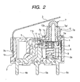
- Fig. 2 is a longitudinal sectional view showing a state where this embodiment is assembled
- Fig. 3 is a longitudinal sectional view illustrating the operation of this embodiment.
- this embodiment includes a case which is made up of an upper case 1 and a case base 2 to be fitted to the upper case 1, and forms a main body, and a lever 3 which is rotatably supported by the upper case 1. Further, this embodiment includes at least a pair of fixed contacts 4, for example, a first contact and a second contact 5 constituting a switching contact portion, and a common contact 6, which are provided, for example, uprightly in the upper case 1.
- the first contact 4, the second contact 5, and the common contact 6 are insert-molded into the case base 2 made of insulating resin. Further, corresponding terminals-4a, 5a, and 6a are connected to the first contact 4, the second contact 5, and the common contact 6, respectively.
- this embodiment includes an operating member 7 which is held inside the upper case 1 so as to be movable, that is, linearly and slidingly movable in Fig. 2 , for example, vertically movable, and which is composed of an operating portion 7a to which the pressing force of the lever 3 is to be applied, and an holding portion 7b which is connected to the operating portion 7a to hold a movable contact 8.
- this embodiment has a biasing member 9, for example, a coil spring which biases the operating member 7 toward an initial position.
- a water-proof and dust-proof rubber cap 10 is engaged with a portion in the vicinity of the upper end of the operating portion 7a of the operating member 7.
- Fig. 4 is a view showing the upper case with which this embodiment is equipped, and the (a) figure is a perspective view which observed the plan view and the (b) figure from the rear surface side.
- the above-mentioned upper case 1 has a guide portion, for example, a guide hole 1a which guides the operating portion 7a which forms a guided portion of the operating member 7. Further, as shown in Fig. 4B , a pair of recesses 1d which form another guide portion for the operating member 7 are provided inside the upper case 1. Further, as shown in Fig. 2 , etc., one end of the upper case 1 is provided with a supporting portion 1b with which a cut and raised portion 3a formed at a lower end of the lever 3 is to be engaged, and an outside portion of the guide hole 1a is provided with an annular groove 1c with which the rubber cap 10 is to be engaged.
- a guide portion for example, a guide hole 1a which guides the operating portion 7a which forms a guided portion of the operating member 7.
- a pair of recesses 1d which form another guide portion for the operating member 7 are provided inside the upper case 1.
- one end of the upper case 1 is provided with a supporting portion 1b with which a cut and raised portion 3
- Figs. 5A and 5B are views showing the operating member provided in this embodiment
- Fig. 5A is a plan view
- Fig. 5B is a perspective view as seen from the rear surface side
- Fig. 6 is a view showing the attachment relationship between the operating member and the biasing member, which are provided in this embodiment, and is a view as seen from the rear surface side of the operating member.
- the operating portion 7a of the above-mentioned operating member 7 has a basic shape which is formed, for example, in a cylindrical shape, and its upper end is provided with an annular groove 7a1 with which the above-mentioned rubber cap 10 is to be engaged.
- the rubber cap 10 as shown in Fig. 1 , has an upper end 10a engaged with the annular groove 7a1 of the operating portion 7a, and has a flange portion 10b forming a lower end engaged with the annular groove 1c of the upper case 1 shown in Fig. 2 , etc.
- the holding portion 7b of the operating member 7 has, for example, a pair of shieldable walls 7b3 which are provided to face each other and which cover the whole movable contact 8 held in the holding portion 7b.
- the pair of walls 7b3 are provided so as to run along a rotation surface of the lever 3.
- Inside portions of the pair of walls 7b3 are provided with recesses 7b1 which form a substantially circular hole, and as shown in Fig. 6 , four protruding portions 7b2 which can hold an upper end of the above-mentioned coil spring 9 are formed in the recesses 7b1.
- Outside portions of the pair of walls 7b3 are formed with guided portions, for example, a pair of convex portions 7b4 which are respectively guided by the recesses 1d which are the guide portions of the above-mentioned upper case 1.
- a guide portion arranged so as to run along the rotation surface of the lever 3 is constituted by the guide hole 1a and the recesses 1d of the upper case 1, and a guided portion which is guided by the guide portion of the upper case 1 is constituted by the operating portion 7a and the convex portions 7b4 of the operating member 7.
- Figs. 7A and 7B are views showing the movable contact provided in this embodiment
- Fig. 7A is a plan view
- Fig. 7B is a perspective view as seen from the rear surface _side
- Fig. 8 is a view showing the attachment relationship between the operating member and the movable contact, which are provided in this embodiment, and is a view as seen from the rear surface side of the operating member.
- the movable contact 8 which slides on the first contact 4, the second contact 5, and the common contact 6 which form switching contact portions which are fixed contacts to perform switching of the contacts is made of a metal plate, is formed so as to be bent, and as shown Fig. 7A , etc., includes at least a pair of elastic arms, for example, a first elastic arm 8a and a second elastic arm 8b.
- a first elastic arm 8a As shown in Fig. 7B , etc., an inside portion of the first elastic arm 8a is formed with two first contact portions 8a1 arranged so as to face each other as contact portions
- an inside portion of the second elastic arm 8b is formed with two second contact portions 8b1 arranged so as to face each other as contact portions. That is, the movable contact 8 is provided with, for example, the first contact portions 8a1 and the second contact portions 8b1 formed in the pair of elastic arms, respectively.
- the movable contact 8 as shown in Fig. 7B , has a flat connecting portion 8c which connects the first elastic arm 8a and the second elastic arm 8b.
- a central portion of the connecting portion 8c is provided with a substantially circular large-diameter portion 8c1 which is formed so as to project therefrom.
- the large-diameter portion 8c1 formed in the connecting portion 8c of the movable contact 8 abuts on and is accommodated in flat ceiling surfaces of the recesses 7b1 formed in the holding portion 7b of the operating member 7.
- an outer peripheral edge of the connecting portion 8c is, for example, temporarily caulked by the recesses 7b1 or the walls 7b3, and an upper end of the coil spring 9 abuts on a bottom surface of the large-diameter portion 8c1 so that the movable contact 8 may be held by the holding portion 7b of the operating member 7 while receiving the biasing force of the coil spring 9.
- the flat large-diameter portion 8c1 of the movable contact 8 abuts on the flat ceiling surfaces of the recesses 7b1 while receiving the biasing force of the coil spring 9, the movable contact 8 is hardly inclined.
- the coil spring 9 deviates from the operating portion 7a which projects from the guide hole 1a of the upper case 1, and is held in the vicinity of one end of the upper case 1. As such, by holding the coil spring 9 so as to deviate from the operating portion 7a, the operating portion 7a can be arranged on the side of the other end of the upper case 1.
- the upper end of the coil spring 9 is made to abut on the surface, which is a bottom surface of the connecting portion 8c, opposite to the operating member 7.
- a spacer, etc. may be interposed between the connecting portion 8c and the upper end of the coil spring 9 so as to bias the movable contact 8 toward the operating member 7.
- the movable contact 8 as shown in Fig. 7A , is formed bilaterally symmetrically (plane-symmetrically) with respect to the middle of the connecting portion 8c as a plane of symmetry.
- the two first contact portions 8a1 formed in the first elastic arm 8a and the two second contact portions 8b1 formed in the second elastic arm 8b are distributively arranged on both sides across a position corresponding to the operating portion 7a of the operating member 7, for example, on the right and left with respect to the recesses 7b1, that is, across a position near a portion directly below the operating portion 7a.
- the first contact portions 8a1 formed in the first elastic arm 8a of the movable contact 8 are always electrically connected to the common contact 6, and are adapted to be slidable so as to sandwich the common contact 6.
- the second contact portions 8b1 formed in the second elastic arm 8b are selectively electrically connected to the first contact 4 and the second contact 5 which constitute a switching contact portion, and are adapted to be slidable so as to sandwich the first contact 4 or the second contact 5.
- first elastic arm 8a and the second elastic arm 8b which are formed bilaterally symmetrically with respect to the connecting portion 8c will be explained in detail.
- first elastic arm 8a and the second elastic arm 8b are bilaterally symmetrical, and have the same shape, only the description of the first elastic arm 8a will be made, and the description of the second elastic arm 8b will be omitted.
- the first elastic arm 8a is constituted by a pair of elastic pieces which are bent such that their plate surfaces face each other with a predetermined space from a flat elastic arm connecting portion 8a2 which extends outward from the connecting portion 8c.
- the first elastic arm 8a forms a substantial U shape in plan view. That is, as shown in Figs. 2 and 3 , one first contact portion is composed of a first extending portion 8a3 which extends by a predetermined distance from the elastic arm connecting portion 8a2 toward an inner bottom surface (downward in Fig.
- a second extending portion 8a4 which extends from its end on the side of the inner bottom surface of the case base 2 to a position where it faces the common contact 6, and a third extending portion 8a5 which extends to a position which becomes almost equal to the position of the connecting portion 8c substantially parallel to the first extending portion 8a3 from its end on the side of the common contact (so as to run along the common contact 6 which extends from the inner bottom surface of the case base 2).
- the tips of a pair of mutually facing third extending portions 8a5 of the first elastic arm 8a becomes free ends, and the pair of tips are bent portions which project toward the common contact 6.
- the pair of bent portions are composed of the two first contact portions 8a1.
- the first and second elastic arms 8a and 8b configured in this way move along the common contact 6, the first contact 4, or the second contact 5 with the vertical movement of the operating member 7, in a state where the first contact portions 8a1 sandwich the common contact 6, and the second contact portions 8b1 sandwich the first contact 4 or the second contact 5, with the second extending portions 8a4 directed toward the inner bottom surface of the case base 2.
- first and second elastic arms 8a and 8b have a substantial U shape in plan view in this embodiment, a long spring span is taken.
- the contact between the first and second contact portions 8a1 and 8b1 and their corresponding fixed contacts stabilized, and its reliability is enhanced.
- miniaturization in the direction in which the first contact 4, the second contact 5, and the common contact 6 extend, i.e., the direction in which fixed contacts extend, is allowed.
- first and second elastic arms 8a and 8b is not limited to a pair of substantial U shapes in plan view, and may be, for example, such a shape that a pair of elastic pieces extend linearly outward from the connecting portion 8c of the movable contact 8, and a contact portion is provided between their tips.
- Fig. 9 is a front view showing the arrangement relationship between the fixed contacts and the case base, which are provided in this embodiment, and Fig. 10 is an exploded view of the fixed contacts and the case base, which are shown in Fig. 9 .
- the first contact 4, the second contact 5, and the common contact 6 which form the fixed contacts shown in Figs. 9 and 10 are formed of metal, respectively.
- the first contact 4 and the second contact 5 which constitute a switching contact portion are arranged on the side near one end of the upper case 1 where the supporting portion 1b is provided, and the common contact 6 is arranged on the side apart from the one end of the upper case 1.
- the first contact 4 and the second contact 5 which constitute a switching contact portion are arranged along the sliding direction of the movable contact 8 across the insulating portion 11 made of insulating resin, that is, apart from each other in the vertical direction of Fig. 2 .
- the insulating portion 11, the first contact 4, and the second contact 5 are arranged such that the surface of the insulating portion 11 becomes flush with the surfaces of the first contact 4 and the second contact 5. Further, as shown in Fig. 10 , etc., grooves 11a are respectively provided in the central portions of the front and rear surfaces of the insulating portion 11.
- routing regions of the terminals 4a and 5a of the first contact 4 and the second contact 5 are set in a portion within the upper case 1 located between the supporting portion 1b for the lever 3 arranged at one end of the upper case 1, and the coil spring 9 arranged on the bottom surface of the movable contact 8.
- the common contact 6 is sandwiched by the two first contact portions 8a1 formed in the first elastic arm 8a of the movable contact 8, and a fixed contact constituting a switching contact portion, i.e., the first contact 4 is sandwiched by the two second contact portions 8b1 formed in the second elastic arm 8b. That is, the common contact 6 and the first contact 4 are electrically connected to each other via the movable contact 8, resulting in a first ON state.
- the first contact 4 and the second contact 5 which form fixed contacts, and the common contact 6 are cut off from one another, resulting in an OFF state.
- the rubber cap 10 is bent with the movement of the operating portion 7a of the operating member 7 during such operation. Further, the operating portion 7a of the operating member 7 is guided by the guide hole 1a of the upper case 1, and the convex portions 7b4 of the holding portion 7b of the operating member 7 are guided by the recesses 1d of the upper case 1.
- the operating member 7 When the pressing force applied to the lever 3 is removed, the operating member 7 returns to its initial position via the movable contact 8 by the biasing force of the coil spring 9. In this state, as mentioned above, the first contact 4 which forms a fixed contact and the common contact 6 are electrically connected to each other via the movable contact 8, resulting in a first ON state. As such, switching of ON and OFF is performed according to the pressing operation of the lever 3.
- At least a pair of contact portions of the movable contact 8, i.e., the two first contact portions 8a1 formed in the first elastic arm 8a and the two second contact portions 8b1 formed in the second elastic arm 8b are distributively arranged on the right and left of a corresponding position of the operating portion 7a of the operating member 7. That is, the first contact portions 8a1 and the second contact portions 8b1 of the movable contact 8 are distributively arranged on the right and left of a position near the operating portion 7a of the operating member 7, that is, a position near a portion directly under the operating portion 7a.
- the force to be applied to the operating member 7 via the operating portion 7a by the pressing operation of the lever 3 can be dispersed to the right and left of a position corresponding to the operating portion 7a of the operating member 7.
- the frictional force caused between the first contact portions 8a1 of the movable contact 8, and the common contact 6, and the frictional force caused between the second contact portions 8b1 of the movable contact 8, and the first contact 4 or the second contact 5 which forms a fixed contact, or the insulating portion 11 can be dispersed to the right and left of a position corresponding to the operating portion 7a of the operating member 7.
- the upper case 1 is provided with guide portions composed of the guide hole 1a and the recesses 1d which extend so as to run along the rotation surface of the lever 3, and the operating member 7 is provided with the operating portion 7a and the convex portions 7b4 which form guided portions which are guided by the guide portions.
- the operating member 7 can be smoothly moved via the guide portions of the upper case 1, and the guided portions of the operating member 7 without being tilted.
- the guide hole 1a which guides the operating portion 7a of the operating member 7 to which the pressing force of the lever 3 is to be applied is provided in the upper case 1, the tilting of the operating portion 7a of the operating member 7 is suppressed by the upper case 1.
- the tilting of the holding portion 7b of the operating member 7 is suppressed by the upper case 1 via a pair of guided portions, i.e., a pair of convex portions 7b4 provided in the holding portion 7b of the operating member 7, and via a pair of guide portions, i.e., a pair of recesses 1d provided in the upper case 1. These can reliably prevent the tilting of the operating member.
- the shape of the movable contact 8 is formed bilaterally symmetrically. Therefore, attachment of the movable contact 8 to the operating member 7 becomes easy. Further, since the holding portion 7b of the operating member 7 has the pair of walls 7b3 which can be provided to face each other to shield the movable contact 8, attachment of the operating member 7 which holds the movable contact 8 to the upper case 1 becomes easy. These can improve assemblability.
- the pair of walls 7b3 cover the first and second elastic arms 8a and 8b including the first and second contact portions 8a1 and 8b1, the first and second elastic arm 8a and 8b are protected by the pair of walls 7b3 during attachment. This prevents deformation.
- the pair of walls 7b3 cover the whole movable contact 8
- the tilting of the movable contact 8 can be suppressed via the pair of recesses 1d as a pair of guide portions provided in the upper case 1.
- the supporting portion of the lever 3 is arranged at one end of the upper case 1, and as shown in Fig. 2 , etc., the operating member 7 is arranged at the other end of the upper case 1.
- a dead space inside the upper case 1 to be formed between the one end of the upper case 1 and the coil spring 9 can be effectively utilized as routing regions of the terminals 4a and 5a of the first contact 4 and the second contact 5 which forms fixed contacts.
- the insulating portion 11 provided between the first contact 4 and the second contact 5 is made of insulating resin, and the insulating portion 11, the first contact 4, and the second contact 5 are arranged such that the surface of the insulating portion 11 and the surfaces of the first contact 4 and the second contact 5 are included in the same plane.
- the second contact portions 8b1 of the movable contact 8 can be made to slide smoothly and excellent ON and OFF performance can be secured, in a state where contact pressure is kept constant among the surface of the first contact 4 which forms a fixed contact, the surface of the insulating portion 11, and the surface of the second contact 5 which forms a fixed contact during sliding of the movable contact 8 accompanying the movement of the operating member 7 by the pressing operation of the lever 3.
- the surfaces of the insulating portion 11 are provided with the groove 11a.
- the metal powder or resin power generated by the sliding between the second contact portions 8b1 of the movable contact 8, and the first contact 4 and the second contact 5 which form fixed contacts, or by the sliding between the second contact portions 8b1 of the movable contact 8 and the insulating portion 11 made of insulating resin can be accommodated in the grooves 11a of the insulating portion 11 with the sliding of the movable contact 8.
- a switching contact portion is constituted by the first contact 4 and the second contact 5 which are arranged vertically so as to sandwich the insulating portion 11.
- the first contact 4 may be excluded from the above-mentioned configuration, and places other than the first contact 4 may be formed in an insulating portion connected to the insulating portion 11.
- the second contact portions 8b1 of the movable contact 8 contacts the insulating portion connected to the insulating portion 11.
- the common contact 6 and the second contact 5 are cut off from each other, resulting in an OFF state.
- the common contact 6 may be a fixed contact of a switching contact portion adapted to have the same shape as the second contact 5 in which an insulating portion is formed as mentioned above.
- the first and second contact portions 8a1 and 8b1 of the movable contact 8 contact the insulating portions, respectively, resulting in an ON state.
- the first and second contact portions 8a1 of the movable contact 8 and 8b1 contact the fixed contacts by the pressing operation of the lever 3, this results in an ON state. Even in such a configuration, switching of ON and OFF according to the pressing operation of the lever 3 can be performed.
- the above-mentioned embodiment is configured such that the first contact 4 and the second contact 5 which constitute a switching contact portion, and the common contact 6 are provided uprightly from the case base 2 as a pair of fixed contacts in the upper case 1.
- the invention is not limited thereto.
- one fixed contact of a pair of fixed contacts may be erected from a bottom wall of the case base 2, the other fixed contact may be erected from a side wall on the side of one end of the upper case 1.
- the positions where the fixed contacts are erected may be suitably changed.
- the other pair of fixed contacts which have different heights other than a pair of fixed contacts may be provided in positions lower than the pair of fixed contacts, and the other pair of elastic arms may be provided in the movable contact 8 in correspondence to the other pair of fixed contacts. Even in such a configuration, contact portions formed in two pairs of elastic arms of the movable contact 8 are gradually brought into contact with corresponding fixed contacts by the pressing operation of the lever 3, so that an ON and OFF state can be obtained gradually.
- the fixed contacts and the elastic arms are not limited to one pair, and the number thereof to make pairs may be suitably set according to designs.
- the movable contact may not be formed bilaterally symmetrically.
- one elastic arm provided with contact portions which sandwich a common contact may be provided on one side of the movable contact, and a plurality of elastic arms provided with a plurality of contact portions which sandwich a normal open contact and a normal close contact may be provided on the other side of the movable contact.
- the grooves 11a which can accommodate metal powder or resin powder are formed in the central portion of the insulating portion 11.
- the invention is not limited to a configuration in which the grooves 11a are arranged in the central portion of the insulating portion 11.
- the groove 11a may be provided at the end of the insulating portion 11 which be located in a boundary between the first contact 4 and the insulating portion 11, and may be provided at the end of the insulating portion 11 which is located in a boundary between the second contact 5 and the insulating portion 11.
- the grooves may not be provided.
Applications Claiming Priority (1)
| Application Number | Priority Date | Filing Date | Title |
|---|---|---|---|
| JP2007162807A JP2009004175A (ja) | 2007-06-20 | 2007-06-20 | レバー付き押し釦スイッチ装置 |
Publications (3)
| Publication Number | Publication Date |
|---|---|
| EP2006868A2 true EP2006868A2 (de) | 2008-12-24 |
| EP2006868A3 EP2006868A3 (de) | 2009-11-11 |
| EP2006868B1 EP2006868B1 (de) | 2015-05-06 |
Family
ID=39712326
Family Applications (1)
| Application Number | Title | Priority Date | Filing Date |
|---|---|---|---|
| EP20080011173 Active EP2006868B1 (de) | 2007-06-20 | 2008-06-19 | Schaltvorrichtung mit Druckknopf und Hebel |
Country Status (3)
| Country | Link |
|---|---|
| EP (1) | EP2006868B1 (de) |
| JP (1) | JP2009004175A (de) |
| CN (1) | CN101329961B (de) |
Cited By (5)
| Publication number | Priority date | Publication date | Assignee | Title |
|---|---|---|---|---|
| ITRM20110052A1 (it) * | 2011-02-04 | 2012-08-05 | Gianfranco Tinti | Microinterruttore ad azionamento lineare continuo. |
| EP2782111A1 (de) * | 2013-03-19 | 2014-09-24 | Omron Corporation | Schalter |
| EP2908325A1 (de) * | 2014-02-15 | 2015-08-19 | Johnson Electric S.A. | Elektrischer Schalter mit einem Aktuator |
| CN111520837A (zh) * | 2020-05-13 | 2020-08-11 | 青岛海尔空调电子有限公司 | 空调器 |
| EP4084031A1 (de) * | 2021-04-28 | 2022-11-02 | Zippy Technology Corp. | Schaltvorrichtung |
Families Citing this family (4)
| Publication number | Priority date | Publication date | Assignee | Title |
|---|---|---|---|---|
| JP5971586B2 (ja) * | 2012-04-26 | 2016-08-17 | パナソニックIpマネジメント株式会社 | 接点装置 |
| CN106128828A (zh) * | 2016-08-29 | 2016-11-16 | 仝达机电工业(惠州)有限公司 | 一种新型开关 |
| JP2019160649A (ja) * | 2018-03-14 | 2019-09-19 | オムロン株式会社 | マイクロスイッチ、操作装置及びマイクロスイッチの製造方法 |
| CN110189945B (zh) * | 2019-06-10 | 2024-01-16 | 惠州市弘宝电器有限公司 | 一种夹片式微动开关 |
Citations (1)
| Publication number | Priority date | Publication date | Assignee | Title |
|---|---|---|---|---|
| JP2005294112A (ja) | 2004-04-01 | 2005-10-20 | Alps Electric Co Ltd | スイッチ装置 |
Family Cites Families (7)
| Publication number | Priority date | Publication date | Assignee | Title |
|---|---|---|---|---|
| JPS55117729A (en) * | 1979-03-05 | 1980-09-10 | Matsushita Electric Ind Co Ltd | Magnetic head |
| JPS63108129U (de) * | 1986-12-29 | 1988-07-12 | ||
| JPH0896657A (ja) * | 1994-09-27 | 1996-04-12 | Matsushita Electric Works Ltd | プッシュスイッチ |
| DE19530209A1 (de) * | 1995-08-17 | 1997-02-20 | Abb Patent Gmbh | Elektrischer Schalter |
| JPH1145630A (ja) * | 1997-07-28 | 1999-02-16 | Alps Electric Co Ltd | 押し釦スイッチ |
| JP2001256857A (ja) * | 2000-03-14 | 2001-09-21 | Toshiba Video Products Japan Co Ltd | 磁気記録再生機器の動作モード検出スイッチ |
| CN2814650Y (zh) * | 2005-07-27 | 2006-09-06 | 苏州华杰电子有限公司 | 透光式按钮开关 |
-
2007
- 2007-06-20 JP JP2007162807A patent/JP2009004175A/ja not_active Withdrawn
-
2008
- 2008-06-18 CN CN200810125489XA patent/CN101329961B/zh active Active
- 2008-06-19 EP EP20080011173 patent/EP2006868B1/de active Active
Patent Citations (1)
| Publication number | Priority date | Publication date | Assignee | Title |
|---|---|---|---|---|
| JP2005294112A (ja) | 2004-04-01 | 2005-10-20 | Alps Electric Co Ltd | スイッチ装置 |
Cited By (9)
| Publication number | Priority date | Publication date | Assignee | Title |
|---|---|---|---|---|
| ITRM20110052A1 (it) * | 2011-02-04 | 2012-08-05 | Gianfranco Tinti | Microinterruttore ad azionamento lineare continuo. |
| EP2782111A1 (de) * | 2013-03-19 | 2014-09-24 | Omron Corporation | Schalter |
| US20140284195A1 (en) * | 2013-03-19 | 2014-09-25 | Omron Corporation | Switch |
| US9502190B2 (en) | 2013-03-19 | 2016-11-22 | Omron Corporation | Switch |
| EP2908325A1 (de) * | 2014-02-15 | 2015-08-19 | Johnson Electric S.A. | Elektrischer Schalter mit einem Aktuator |
| DE102014006943A1 (de) * | 2014-02-15 | 2015-08-20 | Johnson Electric Germany GmbH & Co. KG | Elektrischer Schalter mit einem eine obere Fläche aufweisenden Gehäuse |
| US9613765B2 (en) | 2014-02-15 | 2017-04-04 | Johnson Electric S.A. | Electric switch with an actuator |
| CN111520837A (zh) * | 2020-05-13 | 2020-08-11 | 青岛海尔空调电子有限公司 | 空调器 |
| EP4084031A1 (de) * | 2021-04-28 | 2022-11-02 | Zippy Technology Corp. | Schaltvorrichtung |
Also Published As
| Publication number | Publication date |
|---|---|
| CN101329961A (zh) | 2008-12-24 |
| EP2006868A3 (de) | 2009-11-11 |
| CN101329961B (zh) | 2011-12-28 |
| EP2006868B1 (de) | 2015-05-06 |
| JP2009004175A (ja) | 2009-01-08 |
Similar Documents
| Publication | Publication Date | Title |
|---|---|---|
| EP2006868B1 (de) | Schaltvorrichtung mit Druckknopf und Hebel | |
| JP4469878B2 (ja) | 押釦スイッチ | |
| US7122756B2 (en) | Push switch | |
| JP4248563B2 (ja) | プッシュスイッチ | |
| KR102176433B1 (ko) | 키 스위치 장치 | |
| EP2741164A1 (de) | Druckschalter | |
| US20030057081A1 (en) | Contact block assembly and a method of assembling a contact block assembly | |
| US20050145473A1 (en) | Microswitch | |
| US6150624A (en) | Keyswitch device | |
| US9105416B2 (en) | Push switch | |
| US6689967B2 (en) | Slide switch | |
| US6559393B2 (en) | Switch having a seesaw type movable contact blade | |
| KR20130006306A (ko) | 스위치 | |
| JP4735452B2 (ja) | プッシュスイッチ | |
| AU2018204641A1 (en) | Push-button switch | |
| JP2022043622A (ja) | プッシュスイッチ | |
| JP2007207563A (ja) | 電気装置の操作機構 | |
| EP3582243B1 (de) | Vierwegeschalter mit fehlfunktionverhinderungsstruktur | |
| US6797904B1 (en) | Microswitch | |
| JP4619196B2 (ja) | 押圧スイッチ付き摺動式電子部品 | |
| JP4256708B2 (ja) | スイッチ装置 | |
| KR200461085Y1 (ko) | 로커 스위치 | |
| JP2011108429A (ja) | 押圧スイッチ | |
| US20140202842A1 (en) | Push button switch | |
| JP3352680B2 (ja) | キースイッチ装置 |
Legal Events
| Date | Code | Title | Description |
|---|---|---|---|
| PUAI | Public reference made under article 153(3) epc to a published international application that has entered the european phase |
Free format text: ORIGINAL CODE: 0009012 |
|
| AK | Designated contracting states |
Kind code of ref document: A2 Designated state(s): AT BE BG CH CY CZ DE DK EE ES FI FR GB GR HR HU IE IS IT LI LT LU LV MC MT NL NO PL PT RO SE SI SK TR |
|
| AX | Request for extension of the european patent |
Extension state: AL BA MK RS |
|
| PUAL | Search report despatched |
Free format text: ORIGINAL CODE: 0009013 |
|
| AK | Designated contracting states |
Kind code of ref document: A3 Designated state(s): AT BE BG CH CY CZ DE DK EE ES FI FR GB GR HR HU IE IS IT LI LT LU LV MC MT NL NO PL PT RO SE SI SK TR |
|
| AX | Request for extension of the european patent |
Extension state: AL BA MK RS |
|
| 17P | Request for examination filed |
Effective date: 20100122 |
|
| 17Q | First examination report despatched |
Effective date: 20100316 |
|
| AKX | Designation fees paid |
Designated state(s): AT BE BG CH CY CZ DE DK EE ES FI FR GB GR HR HU IE IS IT LI LT LU LV MC MT NL NO PL PT RO SE SI SK TR |
|
| GRAP | Despatch of communication of intention to grant a patent |
Free format text: ORIGINAL CODE: EPIDOSNIGR1 |
|
| INTG | Intention to grant announced |
Effective date: 20141209 |
|
| GRAS | Grant fee paid |
Free format text: ORIGINAL CODE: EPIDOSNIGR3 |
|
| GRAA | (expected) grant |
Free format text: ORIGINAL CODE: 0009210 |
|
| AK | Designated contracting states |
Kind code of ref document: B1 Designated state(s): AT BE BG CH CY CZ DE DK EE ES FI FR GB GR HR HU IE IS IT LI LT LU LV MC MT NL NO PL PT RO SE SI SK TR |
|
| REG | Reference to a national code |
Ref country code: GB Ref legal event code: FG4D |
|
| REG | Reference to a national code |
Ref country code: CH Ref legal event code: EP |
|
| REG | Reference to a national code |
Ref country code: FR Ref legal event code: PLFP Year of fee payment: 8 |
|
| REG | Reference to a national code |
Ref country code: IE Ref legal event code: FG4D |
|
| REG | Reference to a national code |
Ref country code: AT Ref legal event code: REF Ref document number: 726204 Country of ref document: AT Kind code of ref document: T Effective date: 20150615 |
|
| REG | Reference to a national code |
Ref country code: DE Ref legal event code: R096 Ref document number: 602008038002 Country of ref document: DE Effective date: 20150618 |
|
| REG | Reference to a national code |
Ref country code: AT Ref legal event code: MK05 Ref document number: 726204 Country of ref document: AT Kind code of ref document: T Effective date: 20150506 |
|
| REG | Reference to a national code |
Ref country code: NL Ref legal event code: MP Effective date: 20150506 |
|
| REG | Reference to a national code |
Ref country code: LT Ref legal event code: MG4D |
|
| PG25 | Lapsed in a contracting state [announced via postgrant information from national office to epo] |
Ref country code: NO Free format text: LAPSE BECAUSE OF FAILURE TO SUBMIT A TRANSLATION OF THE DESCRIPTION OR TO PAY THE FEE WITHIN THE PRESCRIBED TIME-LIMIT Effective date: 20150806 Ref country code: PT Free format text: LAPSE BECAUSE OF FAILURE TO SUBMIT A TRANSLATION OF THE DESCRIPTION OR TO PAY THE FEE WITHIN THE PRESCRIBED TIME-LIMIT Effective date: 20150907 Ref country code: HR Free format text: LAPSE BECAUSE OF FAILURE TO SUBMIT A TRANSLATION OF THE DESCRIPTION OR TO PAY THE FEE WITHIN THE PRESCRIBED TIME-LIMIT Effective date: 20150506 Ref country code: LT Free format text: LAPSE BECAUSE OF FAILURE TO SUBMIT A TRANSLATION OF THE DESCRIPTION OR TO PAY THE FEE WITHIN THE PRESCRIBED TIME-LIMIT Effective date: 20150506 Ref country code: ES Free format text: LAPSE BECAUSE OF FAILURE TO SUBMIT A TRANSLATION OF THE DESCRIPTION OR TO PAY THE FEE WITHIN THE PRESCRIBED TIME-LIMIT Effective date: 20150506 Ref country code: FI Free format text: LAPSE BECAUSE OF FAILURE TO SUBMIT A TRANSLATION OF THE DESCRIPTION OR TO PAY THE FEE WITHIN THE PRESCRIBED TIME-LIMIT Effective date: 20150506 |
|
| PG25 | Lapsed in a contracting state [announced via postgrant information from national office to epo] |
Ref country code: AT Free format text: LAPSE BECAUSE OF FAILURE TO SUBMIT A TRANSLATION OF THE DESCRIPTION OR TO PAY THE FEE WITHIN THE PRESCRIBED TIME-LIMIT Effective date: 20150506 Ref country code: LV Free format text: LAPSE BECAUSE OF FAILURE TO SUBMIT A TRANSLATION OF THE DESCRIPTION OR TO PAY THE FEE WITHIN THE PRESCRIBED TIME-LIMIT Effective date: 20150506 Ref country code: GR Free format text: LAPSE BECAUSE OF FAILURE TO SUBMIT A TRANSLATION OF THE DESCRIPTION OR TO PAY THE FEE WITHIN THE PRESCRIBED TIME-LIMIT Effective date: 20150807 Ref country code: IS Free format text: LAPSE BECAUSE OF FAILURE TO SUBMIT A TRANSLATION OF THE DESCRIPTION OR TO PAY THE FEE WITHIN THE PRESCRIBED TIME-LIMIT Effective date: 20150906 Ref country code: BG Free format text: LAPSE BECAUSE OF FAILURE TO SUBMIT A TRANSLATION OF THE DESCRIPTION OR TO PAY THE FEE WITHIN THE PRESCRIBED TIME-LIMIT Effective date: 20150806 |
|
| PG25 | Lapsed in a contracting state [announced via postgrant information from national office to epo] |
Ref country code: EE Free format text: LAPSE BECAUSE OF FAILURE TO SUBMIT A TRANSLATION OF THE DESCRIPTION OR TO PAY THE FEE WITHIN THE PRESCRIBED TIME-LIMIT Effective date: 20150506 Ref country code: DK Free format text: LAPSE BECAUSE OF FAILURE TO SUBMIT A TRANSLATION OF THE DESCRIPTION OR TO PAY THE FEE WITHIN THE PRESCRIBED TIME-LIMIT Effective date: 20150506 |
|
| REG | Reference to a national code |
Ref country code: CH Ref legal event code: PL |
|
| REG | Reference to a national code |
Ref country code: DE Ref legal event code: R097 Ref document number: 602008038002 Country of ref document: DE |
|
| PG25 | Lapsed in a contracting state [announced via postgrant information from national office to epo] |
Ref country code: PL Free format text: LAPSE BECAUSE OF FAILURE TO SUBMIT A TRANSLATION OF THE DESCRIPTION OR TO PAY THE FEE WITHIN THE PRESCRIBED TIME-LIMIT Effective date: 20150506 Ref country code: RO Free format text: LAPSE BECAUSE OF NON-PAYMENT OF DUE FEES Effective date: 20150506 Ref country code: SK Free format text: LAPSE BECAUSE OF FAILURE TO SUBMIT A TRANSLATION OF THE DESCRIPTION OR TO PAY THE FEE WITHIN THE PRESCRIBED TIME-LIMIT Effective date: 20150506 Ref country code: CZ Free format text: LAPSE BECAUSE OF FAILURE TO SUBMIT A TRANSLATION OF THE DESCRIPTION OR TO PAY THE FEE WITHIN THE PRESCRIBED TIME-LIMIT Effective date: 20150506 Ref country code: MC Free format text: LAPSE BECAUSE OF FAILURE TO SUBMIT A TRANSLATION OF THE DESCRIPTION OR TO PAY THE FEE WITHIN THE PRESCRIBED TIME-LIMIT Effective date: 20150506 |
|
| PLBE | No opposition filed within time limit |
Free format text: ORIGINAL CODE: 0009261 |
|
| STAA | Information on the status of an ep patent application or granted ep patent |
Free format text: STATUS: NO OPPOSITION FILED WITHIN TIME LIMIT |
|
| REG | Reference to a national code |
Ref country code: IE Ref legal event code: MM4A |
|
| 26N | No opposition filed |
Effective date: 20160209 |
|
| PG25 | Lapsed in a contracting state [announced via postgrant information from national office to epo] |
Ref country code: CH Free format text: LAPSE BECAUSE OF NON-PAYMENT OF DUE FEES Effective date: 20150630 Ref country code: IE Free format text: LAPSE BECAUSE OF NON-PAYMENT OF DUE FEES Effective date: 20150619 Ref country code: LI Free format text: LAPSE BECAUSE OF NON-PAYMENT OF DUE FEES Effective date: 20150630 |
|
| PG25 | Lapsed in a contracting state [announced via postgrant information from national office to epo] |
Ref country code: SI Free format text: LAPSE BECAUSE OF FAILURE TO SUBMIT A TRANSLATION OF THE DESCRIPTION OR TO PAY THE FEE WITHIN THE PRESCRIBED TIME-LIMIT Effective date: 20150506 |
|
| REG | Reference to a national code |
Ref country code: FR Ref legal event code: PLFP Year of fee payment: 9 |
|
| PG25 | Lapsed in a contracting state [announced via postgrant information from national office to epo] |
Ref country code: BE Free format text: LAPSE BECAUSE OF FAILURE TO SUBMIT A TRANSLATION OF THE DESCRIPTION OR TO PAY THE FEE WITHIN THE PRESCRIBED TIME-LIMIT Effective date: 20150506 |
|
| PG25 | Lapsed in a contracting state [announced via postgrant information from national office to epo] |
Ref country code: MT Free format text: LAPSE BECAUSE OF FAILURE TO SUBMIT A TRANSLATION OF THE DESCRIPTION OR TO PAY THE FEE WITHIN THE PRESCRIBED TIME-LIMIT Effective date: 20150506 |
|
| PG25 | Lapsed in a contracting state [announced via postgrant information from national office to epo] |
Ref country code: HU Free format text: LAPSE BECAUSE OF FAILURE TO SUBMIT A TRANSLATION OF THE DESCRIPTION OR TO PAY THE FEE WITHIN THE PRESCRIBED TIME-LIMIT; INVALID AB INITIO Effective date: 20080619 |
|
| REG | Reference to a national code |
Ref country code: FR Ref legal event code: PLFP Year of fee payment: 10 |
|
| PG25 | Lapsed in a contracting state [announced via postgrant information from national office to epo] |
Ref country code: SE Free format text: LAPSE BECAUSE OF FAILURE TO SUBMIT A TRANSLATION OF THE DESCRIPTION OR TO PAY THE FEE WITHIN THE PRESCRIBED TIME-LIMIT Effective date: 20150506 Ref country code: NL Free format text: LAPSE BECAUSE OF FAILURE TO SUBMIT A TRANSLATION OF THE DESCRIPTION OR TO PAY THE FEE WITHIN THE PRESCRIBED TIME-LIMIT Effective date: 20150506 Ref country code: CY Free format text: LAPSE BECAUSE OF FAILURE TO SUBMIT A TRANSLATION OF THE DESCRIPTION OR TO PAY THE FEE WITHIN THE PRESCRIBED TIME-LIMIT Effective date: 20150506 |
|
| REG | Reference to a national code |
Ref country code: DE Ref legal event code: R082 Ref document number: 602008038002 Country of ref document: DE Representative=s name: SCHMITT-NILSON SCHRAUD WAIBEL WOHLFROM PATENTA, DE |
|
| PG25 | Lapsed in a contracting state [announced via postgrant information from national office to epo] |
Ref country code: TR Free format text: LAPSE BECAUSE OF FAILURE TO SUBMIT A TRANSLATION OF THE DESCRIPTION OR TO PAY THE FEE WITHIN THE PRESCRIBED TIME-LIMIT Effective date: 20150506 |
|
| PG25 | Lapsed in a contracting state [announced via postgrant information from national office to epo] |
Ref country code: LU Free format text: LAPSE BECAUSE OF NON-PAYMENT OF DUE FEES Effective date: 20150619 |
|
| REG | Reference to a national code |
Ref country code: FR Ref legal event code: PLFP Year of fee payment: 11 |
|
| REG | Reference to a national code |
Ref country code: DE Ref legal event code: R082 Ref document number: 602008038002 Country of ref document: DE Representative=s name: SCHMITT-NILSON SCHRAUD WAIBEL WOHLFROM PATENTA, DE Ref country code: DE Ref legal event code: R081 Ref document number: 602008038002 Country of ref document: DE Owner name: ALPS ALPINE CO., LTD., JP Free format text: FORMER OWNER: ALPS ELECTRIC CO., LTD, TOKYO, JP |
|
| PGFP | Annual fee paid to national office [announced via postgrant information from national office to epo] |
Ref country code: FR Payment date: 20230627 Year of fee payment: 16 Ref country code: DE Payment date: 20230620 Year of fee payment: 16 |
|
| PGFP | Annual fee paid to national office [announced via postgrant information from national office to epo] |
Ref country code: IT Payment date: 20230623 Year of fee payment: 16 Ref country code: GB Payment date: 20230620 Year of fee payment: 16 |