EP2006689A2 - Probenausgabevorrichtung und -verfahren - Google Patents
Probenausgabevorrichtung und -verfahren Download PDFInfo
- Publication number
- EP2006689A2 EP2006689A2 EP08010925A EP08010925A EP2006689A2 EP 2006689 A2 EP2006689 A2 EP 2006689A2 EP 08010925 A EP08010925 A EP 08010925A EP 08010925 A EP08010925 A EP 08010925A EP 2006689 A2 EP2006689 A2 EP 2006689A2
- Authority
- EP
- European Patent Office
- Prior art keywords
- nozzle tip
- sample
- suction
- clogging
- separating agent
- Prior art date
- Legal status (The legal status is an assumption and is not a legal conclusion. Google has not performed a legal analysis and makes no representation as to the accuracy of the status listed.)
- Granted
Links
Images


Classifications
-
- G—PHYSICS
- G01—MEASURING; TESTING
- G01N—INVESTIGATING OR ANALYSING MATERIALS BY DETERMINING THEIR CHEMICAL OR PHYSICAL PROPERTIES
- G01N35/00—Automatic analysis not limited to methods or materials provided for in any single one of groups G01N1/00 - G01N33/00; Handling materials therefor
- G01N35/10—Devices for transferring samples or any liquids to, in, or from, the analysis apparatus, e.g. suction devices, injection devices
- G01N35/1009—Characterised by arrangements for controlling the aspiration or dispense of liquids
- G01N35/1016—Control of the volume dispensed or introduced
-
- G—PHYSICS
- G01—MEASURING; TESTING
- G01N—INVESTIGATING OR ANALYSING MATERIALS BY DETERMINING THEIR CHEMICAL OR PHYSICAL PROPERTIES
- G01N15/00—Investigating characteristics of particles; Investigating permeability, pore-volume or surface-area of porous materials
- G01N15/04—Investigating sedimentation of particle suspensions
- G01N15/042—Investigating sedimentation of particle suspensions by centrifuging and investigating centrifugates
-
- G—PHYSICS
- G01—MEASURING; TESTING
- G01N—INVESTIGATING OR ANALYSING MATERIALS BY DETERMINING THEIR CHEMICAL OR PHYSICAL PROPERTIES
- G01N35/00—Automatic analysis not limited to methods or materials provided for in any single one of groups G01N1/00 - G01N33/00; Handling materials therefor
- G01N35/10—Devices for transferring samples or any liquids to, in, or from, the analysis apparatus, e.g. suction devices, injection devices
- G01N35/1009—Characterised by arrangements for controlling the aspiration or dispense of liquids
- G01N35/1016—Control of the volume dispensed or introduced
- G01N2035/1018—Detecting inhomogeneities, e.g. foam, bubbles, clots
Definitions
- the present invention relates to a sample dispensing apparatus and method. More particularly, it relates to a sample dispensing apparatus for and a method of dispensing a sample by use of a disposable nozzle tip, unloading the dispensed sample to a transfer line, and transferring it to an analyzer or the like.
- Japanese Patent No. 3410018 describes a dispensing apparatus in which after a sample is sucked by a nozzle tip disposable for each sample therein, the sucked sample is delivered into a secondary sample vessel to automatically dispense a sample such as blood an urine by a certain quantity necessary for analysis and inspection, from one vessel (primary sample vessel) to another (secondary sample vessel).
- a sample to be subjected to analysis is a serum constituent, blood containing a separating agent having intermediate specific gravity and high viscosity and stored in the primary sample vessel, is separated into three layers (serum constituent, separating agent, and blood clot constituent) by use of a centrifugal separator.
- the separating agent is used between the serum constituent and the blood clot constituent to prevent the three layers from being re-mixed.
- dispensing is performed to use only the serum constituent for analysis.
- the serum constituent in the primary sample vessel is sucked into the nozzle tip by a required quantity, if the quantity of the serum constituent is not sufficient, the opening at the free end of the nozzle tip comes into contact with the separating agent, resulting in clogging.
- the serum constituent already sucked when clogging has been detected is delivered to the secondary sample vessel, while it is necessary to decrease the serum constituent left in the primary sample vessel.
- a relevant technique is disclosed in, for example, JP-A-7-27679 . With this technique, if clogging occurs, the serum constituent sucked in the nozzle tip is returned and then re-sucked.
- JP-A-7-27679 proposes a technique of returning the serum constituent sucked into the nozzle tip and then re-sucking it if clogging occurs. With this technique, however, since the serum constituent is returned and then re-sucked, it takes much time for processing and the primary sample is disturbed, which may damage the sample.
- An object of the present invention is to provide a sample dispensing apparatus and method which dispenses a sample (primary sample) such as blood and urine collected for inspection from one vessel to another, wherein the remaining quantity of a primary sample can be reduced without disturbing of the primary sample.
- a sample primary sample
- the above-mentioned object of the present invention can be attained by, when clogging of an opening at the free end of a nozzle tip caused by a separating agent is detected, raising an aliquot head such that the opening at the free end of the nozzle tip does not come out of the liquid surface of serum constituent to dissolve the clogging; sucking the serum constituent under the residual pressure; and additionally sucking a fixed quantity thereof after the residual pressure drops.
- Fig. 1 is a diagram exemplifying the configuration of a sample dispensing apparatus (including a control system).
- the sample dispensing apparatus includes a dispenser 100, an aliquot control CPU (Central Processing Unit) 200, a transfer path control CPU 300, and a host CPU 400.
- the dispenser 100 includes an aliquot head 1 and a XYZ moving mechanism 50.
- a plurality of aliquot heads 1 (#1 and #2 in Fig. 1 ) are mounted to the XYZ moving mechanism 50 to perform dispensing operation of samples such as serum and urine.
- the aliquot head 1 is mainly composed of: a nozzle base 1a to which a nozzle tip 2 is attached; a vacuum suction unit 1b which sucks and discharges the sample; a pressure detector 1c which converts pressure change during suction and discharging into an electrical signal; and a signal processing circuit 1d.
- the sample is sucked and charged from an opening at the free end of the nozzle tip 2.
- the vacuum suction unit 1b is composed of a pump mechanism including bellows, syringe, etc. (not shown).
- the signal processing circuit 1d processes an output signal of the pressure detector 1c attached in the aliquot head 1, and the processed signal is sent to the aliquot control CPU 200 for dispensing, failure detection, processing, etc.
- the host CPU 400, the transfer path control CPU 300, and the aliquot control CPU 200 are connected by a local data communication line.
- the transfer path control CPU 300 performs transfer control of a sample rack.
- the aliquot control CPU 200 inquires the host CPU 400 of aliquot information through a rack ID (identification code) and sends aliquot result information thereto. Further, the aliquot control CPU 200 controls dispensing process for the XYZ moving mechanism 50 and the aliquot head 1 of the dispenser 100, and the sample transfer mechanism in the XYZ moving mechanism 50 to perform a series of dispensing operations.
- the dispensing process to be performed by the aliquot control CPU 200 includes sample suction (to be mentioned later).
- One or a plurality of primary sample vessels 3 containing a primary sample are mounted on a rack 4 for sample vessel transfer and transferred on a rack basis.
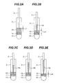
- Figs. 2A to 2E views showing an embodiment of assistance in explaining the outline of sample suction by the sample dispensing apparatus.
- the nozzle tip 2 is lowered to detect the liquid surface of serum 10.
- the leading end of the nozzle tip is immersed into the liquid by an amount of immersion L1 specified based on the delay from detection to stop and the sample quantity to be left.
- the serum 10 is sucked from the detected point and at the same time the nozzle tip 2 is lowered.
- the opening at the leading end of the nozzle tip 2 comes into contact with a separating agent 11 and clogging is detected, the lowering operation of the nozzle tip 2 and sample suction are stopped (suction quantity Qa).
- the height of the residual quantity of the sample is Lx1.
- the nozzle tip 2 is raised such that the leading end of the nozzle tip 2 does not come out of the liquid surface and clogging is dissolved.
- the serum 10 is sucked under the residual pressure in the nozzle tip 2 (suction quantity Qb).
- the residual pressure in the nozzle tip 2 disappears, the serum 10 is further sucked and suction is terminated, followed by discharging (suction quantity Qc).
- the quantity of the left sample becomes Lx2.
- change in the suction quantities is expressed as Qa ⁇ Qb ⁇ Qc. It should be noted that once the sample is sucked into the nozzle tip, it is not returned into the primary sample vessel.
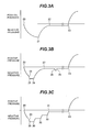
- Figs. 3A to 3C are diagrams exemplifying pressure change in the nozzle tip 2 during suction.
- Fig. 3A shows a suction waveform during normal suction.
- a sample is sucked and discharged by the vacuum suction unit 1b connected with the nozzle tip 2 through an air conduit i.e., the pump mechanism such as bellows and, syringe (not shown, hereinafter represented by bellows).
- bellows are expanded to start suction, and suction is performed until completion-of-suction 22 through stop-of-bellows 21. Then, after a certain time period, bellows are contracted at start-of-dispense 23 to start discharging.
- Fig. 3B shows a suction waveform when clogging occurs.
- Suction starts at start-of-suction 20.
- bellows are stopped at stop-of-bellows 25 and then the aliquot head 1 is raised to dissolve clogging.
- start-of-residual-pressure-suction 26 triggered by the dissolution of clogging until completion-of-residual-pressure 27
- suction is performed under the residual pressure in the nozzle tip 2.
- additional suction is performed since start-of-additional-suction 28 until completion-of-additional-suction 29.
- the sample is discharged by the sample quantity already sucked when clogging has been detected from start-of-dispense 23, the sample quantity sucked under the residual pressure, and the sample quantity additionally sucked.
- Fig. 3C shows a suction waveform in the case where clogging occurs but is not dissolved.
- the discharging operation 30 is performed a plurality of times as shown in Fig. 3C .
- the nozzle tip 2 is raised from the sample with a residual suction pressure, it sucks air and the air introduced in the nozzle tip 2 rapidly rises. As a result, the aliquot head 1 may be soiled by the sample. Therefore, it is necessary to raise the nozzle tip 2 from the sample after the residual pressure has decreased.
- the residual pressure in the nozzle tip 2 disappears at completion-of-residual-pressure-dissolution 31, after a certain time period, sample already sucked when clogging has been detected is dispensed from start-of-dispensing 23.
- Fig. 4 is a diagram of assistance in explaining the overview of an embodiment of a processing flow chart of suction performed by the aliquot control CPU 200.
- the aliquot head 1 When suction is started, the aliquot head 1 is lowered and then the opening at the leading end of the nozzle tip 2 reaches the sample liquid surface for surface detection. When the sample liquid surface is detected, the sample is sucked and at the same time the aliquot head is lowered while following the sample liquid surface. If there is not sufficient quantity of primary sample for the specified suction quantity, the opening at the leading end of the nozzle tip comes into contact with the separating agent during sample suction, clogging is detected, and sample suction and the lowering operation of the aliquot head are stopped.
- the aliquot head is raised such that the opening of the leading end of the nozzle tip does not come out of the surface to dissolve clogging.
- the sample is sucked under the residual pressure in the nozzle tip.
- a fixed quantity of sample is additionally sucked, and suction is completed, followed by discharging.
- the rising distance of the aliquot head and the additional suction quantity after detection of clogging can be separately set from the host CPU or in the dispenser according to the type of aliquot tube used. It should be noted that the additional suction quantity used is the setup value or the quantity calculated by following liquid surface, whichever smaller.
- the aliquot control CPU 200 receives a signal from the pressure detector 1c through the signal processing circuit 1d to supervise pressure change in the nozzle tip.
- the aliquot control CPU 200 based on pressure change in the nozzle tip, performs surface detection, clogging detection, and clogging dissolution detection, etc. For example, pressure change during a period which the opening at the leading end of the nozzle tip reaches the sample liquid surface and sample suction is started is obtained in advance. The pressure change obtained is set as a judgment value. Then, if pressure change detected by the pressure detector 1c exceeds the judgment value, the aliquot control CPU 200 judges that the opening at the leading end of the nozzle tip has reached the sample liquid surface.
- pressure change during a period which the opening at the leading end of the nozzle tip comes into contact with a separating agent during sample suction and clogging occurs is obtained in advance.
- the pressure change obtained is set as a judgment value.
- the aliquot control CPU 200 judges that clogging has occurred.
- pressure change during a period which clogging is dissolved by raising the nozzle tip is obtained in advance.
- the pressure change obtained is set as a judgment value. Allowable time limit between the start of elevation of the nozzle tip and the dissolution of clogging is obtained in advance and the pressure change obtained is set. Then, if pressure change detected by the pressure detector 1c does not become lower than the judgment value within the allowablw time limit, the aliquot control CPU 200 judges that clogging has not been dissolved; otherwise, it judges that clogging has been dissolved.
- the aliquot control CPU 200 outputs a drive instruction in the Z-axis direction (vertical direction) to the XYZ moving mechanism 50 to control the amount of movement in the Z-axis direction of the XYZ moving mechanism 50 and control the amount of movement in the Z-axis direction of the nozzle tip 2.
- the aliquot control CPU 200 outputs a drive instruction to the vacuum suction unit 1b to control the amount of movement of the bellows of the vacuum suction unit 1b thus controlling the suction quantity of the nozzle tip 2.
- the aliquot control CPU 200 Based on the preset amount of movement in the Z-axis direction of the nozzle tip 2 necessary for suction and the amount of movement of the bellows, the aliquot control CPU 200 generates and outputs a drive instruction in the Z-axis direction to the XYZ moving mechanism 50 and a drive instruction to the vacuum suction unit 1b.
- Fig. 5 is a diagram showing a relation between a nozzle tip and height of a sample liquid surface during normal suction operation according to the present invention.
- the nozzle tip 2 is immersed into the sample liquid surface by L1 (at a height position H1) and then suction is started from time t1.
- the sample liquid surface is lowered almost on a first-order lag basis from the lowering operation of the leading end of the nozzle tip 2.
- Settings are set such that time it takes for suction is the same as that for the operation of the nozzle tip 2; operation proceeds between t1 and t2 (at a height position H2).
- Lx a following error between the sample liquid surface and the leading end of the nozzle tip 2 becomes a value indicated at Lx.
- Lx ⁇ L1 a relation Lx ⁇ L1 must be satisfied.
- the sample is sucked under the residual pressure caused by suction delay and the remaining sample quantity becomes a value indicated at L2.
- the nozzle tip 2 is lowered so that L2 substantially equals L1.
- L1 ( ⁇ L2) denotes the quantity of the primary sample that has been left.
- L1 can be set in milliseconds as the quantity of the primary sample to be stored for re-inspection.
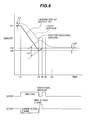
- Fig. 6 is a diagram showing a relation between the nozzle tip 2 and the sample liquid surface when suction clogging occurs.
- the nozzle tip 2 is immersed into the sample liquid surface by L1 (at the height position H1) and then suction is started from time t1.
- a separating agent at time t3 (at the height position H2 of the leading end of the nozzle tip) and then the suction opening at the leading end is blocked, suction clogging is detected and the lowering operation of the nozzle tip 2 and suction are stopped.
- the nozzle tip 2 is raised (at a height position H3) such that the opening does not come out of the sample between t3 and t4.
- the sample is sucked under the residual pressure. Further, when additional suction is performed between t4 and t5, the quantity of the sample left becomes a value indicated at Lx2.
- the amount of elevation of the nozzle tip 2 between t3 and t4 (H3 to H2) and the additional suction quantity between t4 and t5 (quantity equivalent to Lx1 to Lx2) are optimized, so that the sample quantity to be left suffices a portion of the sample associated with the elevation of the nozzle tip 2.
- Lx1 is obtained through calculation from H1, H3, vessel shape (inner diameter, taper, etc.), the suction quantity Qa between t1 and t3.
- the amount of elevation of the nozzle tip 2 H3 to H2
- the additional suction quantity Lx1 to LX2
- the quantity of the sample that is left is problematic in the case of separate dispensing, where it is desirable to set Lx2 to zero.
- suction is balanced with the surface tension of the sample in suction under the residual pressure after time t5 and later, it is possible to further reduce the quantity of the sample to be left without performing air suction.
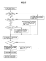
- Fig. 7 is a diagram showing a judgment processing flow for calculating the additional suction quantity according to the present invention performed by the aliquot control CPU 200.
- the additional suction quantity of the type of aliquot tube currently performing processing is set as the additional suction quantity A.
- the additional suction quantity obtained by being calculated or tabled from coordinate values of the height of the leading end of the nozzle tip at which clogging was detected and from the suction quantity accumulated up to suction clogging occurrence, is regarded as an additional suction quantity B.
- the table is stored in a memory.
- the additional suction quantity A is compared with the quantity of additional suction B, and additional suction is performed regarding the value whichever smaller as the additional suction quantity.
- Fig. 7 is a processing flow chart in the case where the quantity of additional suction A obtained from the type of primary sample vessel, and the additional suction quantity B obtained through calculation or a table stored in memory from the suction clogging position and the suction quantity up to suction clogging occurrence, is regarded as a final additional suction quantity. Further, it is also possible to variably set a user-input suction quantity not involving air suction as a additional suction quantity_C, and regard the additional suction quantities A to C, whichever smallest, as a final additional suction quantity. User input can be made using, for example, input means for the host CPU 400 (keyboard, etc.). Further, Fig. 7 is a flow chart for judging the additional suction quantity. Likewise, the amount of elevation of the nozzle tip 2 may be separately set in association to the type of aliquot tube used as a primary sample.
- the above-mentioned method can reduce the remaining quantity of a sample without discharging the sample once sucked into the nozzle tip (without disturbing the primary sample in the vessel 3).
Landscapes
- General Health & Medical Sciences (AREA)
- Health & Medical Sciences (AREA)
- Life Sciences & Earth Sciences (AREA)
- Chemical & Material Sciences (AREA)
- Analytical Chemistry (AREA)
- Biochemistry (AREA)
- Physics & Mathematics (AREA)
- General Physics & Mathematics (AREA)
- Immunology (AREA)
- Pathology (AREA)
- Automatic Analysis And Handling Materials Therefor (AREA)
- Sampling And Sample Adjustment (AREA)
- Investigating Or Analysing Biological Materials (AREA)
Applications Claiming Priority (1)
| Application Number | Priority Date | Filing Date | Title |
|---|---|---|---|
| JP2007164499A JP4982266B2 (ja) | 2007-06-22 | 2007-06-22 | 分注処理装置 |
Publications (3)
| Publication Number | Publication Date |
|---|---|
| EP2006689A2 true EP2006689A2 (de) | 2008-12-24 |
| EP2006689A3 EP2006689A3 (de) | 2016-01-20 |
| EP2006689B1 EP2006689B1 (de) | 2017-12-20 |
Family
ID=39811549
Family Applications (1)
| Application Number | Title | Priority Date | Filing Date |
|---|---|---|---|
| EP08010925.9A Active EP2006689B1 (de) | 2007-06-22 | 2008-06-16 | Probenausgabevorrichtung und -verfahren |
Country Status (4)
| Country | Link |
|---|---|
| US (1) | US8221702B2 (de) |
| EP (1) | EP2006689B1 (de) |
| JP (1) | JP4982266B2 (de) |
| CN (1) | CN101329358B (de) |
Cited By (3)
| Publication number | Priority date | Publication date | Assignee | Title |
|---|---|---|---|---|
| EP2485049A3 (de) * | 2011-02-07 | 2013-04-10 | Ortho-Clinical Diagnostics, Inc. | Erkennung der abgetrennten Komponenten aus zentrifugiertem Blut unter Verwendung eines gemessenen Drucks |
| CN103245774A (zh) * | 2012-02-07 | 2013-08-14 | 奥索临床诊断有限公司 | 使用测定压力确定离心血液中的状况 |
| EP3896460A1 (de) * | 2020-04-17 | 2021-10-20 | bioMérieux | Automatisches probenahmeverfahren zur handhabung von vollblut |
Families Citing this family (15)
| Publication number | Priority date | Publication date | Assignee | Title |
|---|---|---|---|---|
| JP4876027B2 (ja) * | 2007-05-30 | 2012-02-15 | 株式会社日立ハイテクノロジーズ | 分注装置 |
| MX352987B (es) | 2007-10-02 | 2017-12-15 | Theranos Ip Co Llc | Dispositivos modulares de punto de cuidado y usos de los mismos. |
| CN102301242B (zh) * | 2009-01-30 | 2014-07-23 | 株式会社日立高新技术 | 自动分析装置及检测体处理装置 |
| JP5533371B2 (ja) * | 2010-07-09 | 2014-06-25 | 株式会社島津製作所 | オートサンプラ |
| CN106290159A (zh) * | 2011-01-21 | 2017-01-04 | 提拉诺斯公司 | 样品使用最大化的系统和方法 |
| JP5850625B2 (ja) * | 2011-03-02 | 2016-02-03 | シスメックス株式会社 | 分析装置及び位置確認方法 |
| JP2013007579A (ja) * | 2011-06-22 | 2013-01-10 | Seiko Epson Corp | 分注方法 |
| JP2013076674A (ja) * | 2011-09-30 | 2013-04-25 | Fujifilm Corp | 分注装置および吸引ノズル位置制御方法 |
| JP2013255447A (ja) * | 2012-06-12 | 2013-12-26 | Nippon Koden Corp | 細胞単離装置 |
| JP6018828B2 (ja) * | 2012-07-27 | 2016-11-02 | 株式会社日立ハイテクノロジーズ | 自動分析装置 |
| JP2014119387A (ja) * | 2012-12-18 | 2014-06-30 | Sony Corp | 分注装置、分析装置及び分注装置の制御方法 |
| CN106596185B (zh) * | 2016-12-08 | 2019-06-04 | 辽宁石油化工大学 | 小型容器不同空间位置油品取样装置及方法 |
| JP7120063B2 (ja) * | 2019-02-08 | 2022-08-17 | 株式会社島津製作所 | マイクロチップ電気泳動装置及びマイクロチップ電気泳動方法 |
| CN110780085B (zh) * | 2019-11-04 | 2021-03-09 | 苏州长光华医生物医学工程有限公司 | 一种全自动化学发光免疫分析仪的加样方法 |
| CN115469108A (zh) * | 2022-06-30 | 2022-12-13 | 深圳市瑞图生物技术有限公司 | 液基样本处理装置及控制方法 |
Citations (2)
| Publication number | Priority date | Publication date | Assignee | Title |
|---|---|---|---|---|
| JPH0727679A (ja) | 1993-06-24 | 1995-01-31 | Aloka Co Ltd | 全量抜取り分注方法及びその装置 |
| JP3410018B2 (ja) | 1998-04-20 | 2003-05-26 | 株式会社日立製作所 | 検体分注装置及び検体処理システム |
Family Cites Families (10)
| Publication number | Priority date | Publication date | Assignee | Title |
|---|---|---|---|---|
| JPS6264912A (ja) * | 1985-09-17 | 1987-03-24 | Minoru Atake | 分注方式 |
| AU4982093A (en) * | 1993-08-31 | 1995-03-22 | Abbott Laboratories | Pipetting apparatus equipped with closure detection function |
| JPH08338849A (ja) * | 1995-04-11 | 1996-12-24 | Precision Syst Sci Kk | 液体の吸引判別方法およびこの方法により駆動制御される分注装置 |
| JP3820025B2 (ja) * | 1998-03-18 | 2006-09-13 | オリンパス株式会社 | 自動分注装置 |
| US6022747A (en) * | 1998-07-10 | 2000-02-08 | Bayer Corporation | Blood clot detector |
| JP4102863B2 (ja) * | 2003-02-14 | 2008-06-18 | 株式会社スタックシステム | 分注機及び分注装置 |
| US8307722B2 (en) * | 2005-05-19 | 2012-11-13 | Universal Bio Research Co., Ltd. | Method of detecting dispensed quantity, and liquid suction monitoring dispensing apparatus |
| JP4486006B2 (ja) * | 2005-08-05 | 2010-06-23 | 株式会社日立ハイテクノロジーズ | 検体分注処理装置 |
| US7477997B2 (en) * | 2005-12-19 | 2009-01-13 | Siemens Healthcare Diagnostics Inc. | Method for ascertaining interferants in small liquid samples in an automated clinical analyzer |
| JP4876027B2 (ja) * | 2007-05-30 | 2012-02-15 | 株式会社日立ハイテクノロジーズ | 分注装置 |
-
2007
- 2007-06-22 JP JP2007164499A patent/JP4982266B2/ja active Active
-
2008
- 2008-06-16 EP EP08010925.9A patent/EP2006689B1/de active Active
- 2008-06-19 CN CN2008101286123A patent/CN101329358B/zh active Active
- 2008-06-20 US US12/143,339 patent/US8221702B2/en active Active
Patent Citations (2)
| Publication number | Priority date | Publication date | Assignee | Title |
|---|---|---|---|---|
| JPH0727679A (ja) | 1993-06-24 | 1995-01-31 | Aloka Co Ltd | 全量抜取り分注方法及びその装置 |
| JP3410018B2 (ja) | 1998-04-20 | 2003-05-26 | 株式会社日立製作所 | 検体分注装置及び検体処理システム |
Cited By (10)
| Publication number | Priority date | Publication date | Assignee | Title |
|---|---|---|---|---|
| EP2485049A3 (de) * | 2011-02-07 | 2013-04-10 | Ortho-Clinical Diagnostics, Inc. | Erkennung der abgetrennten Komponenten aus zentrifugiertem Blut unter Verwendung eines gemessenen Drucks |
| EP2908131A1 (de) * | 2011-02-07 | 2015-08-19 | Ortho-Clinical Diagnostics Inc | Bestimmung der Zustände in zentrifugiertem Blut unter Verwendung eines gemessenen Drucks |
| RU2611384C2 (ru) * | 2011-02-07 | 2017-02-21 | Орто-Клиникал Дайэгностикс, Инк. | Определение состояний в центрифугированной крови по измеренному давлению |
| US9719906B2 (en) | 2011-02-07 | 2017-08-01 | Ortho-Clinical Diagnostics, Inc. | Determining conditions in centrifuged blood using measured pressure |
| CN103245774A (zh) * | 2012-02-07 | 2013-08-14 | 奥索临床诊断有限公司 | 使用测定压力确定离心血液中的状况 |
| CN108931629A (zh) * | 2012-02-07 | 2018-12-04 | 奥索临床诊断有限公司 | 使用测定压力确定离心血液中的状况 |
| CN108931629B (zh) * | 2012-02-07 | 2024-06-11 | 奥索临床诊断有限公司 | 使用测定压力确定离心血液中的状况 |
| EP3896460A1 (de) * | 2020-04-17 | 2021-10-20 | bioMérieux | Automatisches probenahmeverfahren zur handhabung von vollblut |
| WO2021209378A1 (en) * | 2020-04-17 | 2021-10-21 | bioMérieux | Automatic sampling method for handling whole blood |
| EP4535009A3 (de) * | 2020-04-17 | 2025-10-29 | Biomérieux | Automatisches probenahmeverfahren zur handhabung von vollblut |
Also Published As
| Publication number | Publication date |
|---|---|
| CN101329358A (zh) | 2008-12-24 |
| EP2006689A3 (de) | 2016-01-20 |
| US20080317639A1 (en) | 2008-12-25 |
| JP4982266B2 (ja) | 2012-07-25 |
| US8221702B2 (en) | 2012-07-17 |
| EP2006689B1 (de) | 2017-12-20 |
| CN101329358B (zh) | 2012-02-08 |
| JP2009002816A (ja) | 2009-01-08 |
Similar Documents
| Publication | Publication Date | Title |
|---|---|---|
| EP2006689B1 (de) | Probenausgabevorrichtung und -verfahren | |
| EP1391734A2 (de) | Probenabgabevorrichtung und damit versehener automatischer Analysator | |
| JP2010216876A (ja) | 分析装置および分注プローブ洗浄方法 | |
| WO2006123771A1 (ja) | 分注量検出方法および吸液モニタ型分注装置 | |
| JP5093164B2 (ja) | サンプリング機構 | |
| JP2013053868A (ja) | 自動分析装置 | |
| JP6854292B2 (ja) | 自動分析装置 | |
| WO2007142155A1 (ja) | サンプル分注装置 | |
| JP2000046846A (ja) | 吸引流路の詰まりまたは吸引量不足の検出方法、試料液吸引 装置、及び分注装置 | |
| EP4075146A1 (de) | Automatisierter analysator | |
| JP3451014B2 (ja) | ノズル装置 | |
| JP5536727B2 (ja) | 分注方法及び分注装置 | |
| JP2005201882A (ja) | 使い捨てチップの先端検出方法と使い捨てチップを用いた分注装置 | |
| JP2007322285A (ja) | 分注装置 | |
| JP5111328B2 (ja) | 自動分析装置 | |
| JPH07198726A (ja) | 自動分注装置 | |
| JPH11344498A (ja) | ノズル装置 | |
| US20230236056A1 (en) | Dispensing device, automated analysis device, and dispensing method | |
| JP4876027B2 (ja) | 分注装置 | |
| JP2003194835A (ja) | 分注装置 | |
| WO2022029826A1 (ja) | 分注装置、及び方法 | |
| JP2007132855A (ja) | 液体攪拌方法及び装置 | |
| JP3502588B2 (ja) | 分注装置及び分注方法 | |
| JP2011094985A (ja) | 自動分析装置およびサンプル分注方法 | |
| JP2001296304A (ja) | 分注装置及び方法 |
Legal Events
| Date | Code | Title | Description |
|---|---|---|---|
| PUAI | Public reference made under article 153(3) epc to a published international application that has entered the european phase |
Free format text: ORIGINAL CODE: 0009012 |
|
| AK | Designated contracting states |
Kind code of ref document: A2 Designated state(s): AT BE BG CH CY CZ DE DK EE ES FI FR GB GR HR HU IE IS IT LI LT LU LV MC MT NL NO PL PT RO SE SI SK TR |
|
| AX | Request for extension of the european patent |
Extension state: AL BA MK RS |
|
| 17P | Request for examination filed |
Effective date: 20100331 |
|
| PUAL | Search report despatched |
Free format text: ORIGINAL CODE: 0009013 |
|
| AK | Designated contracting states |
Kind code of ref document: A3 Designated state(s): AT BE BG CH CY CZ DE DK EE ES FI FR GB GR HR HU IE IS IT LI LT LU LV MC MT NL NO PL PT RO SE SI SK TR |
|
| AX | Request for extension of the european patent |
Extension state: AL BA MK RS |
|
| RIC1 | Information provided on ipc code assigned before grant |
Ipc: G01N 35/10 20060101AFI20151216BHEP Ipc: G01N 15/04 20060101ALN20151216BHEP |
|
| AKX | Designation fees paid |
Designated state(s): AT BE BG CH CY CZ DE DK EE ES FI FR GB GR HR HU IE IS IT LI LT LU LV MC MT NL NO PL PT RO SE SI SK TR |
|
| AXX | Extension fees paid |
Extension state: MK Extension state: BA Extension state: AL Extension state: RS |
|
| REG | Reference to a national code |
Ref country code: DE Ref legal event code: R079 Ref document number: 602008053398 Country of ref document: DE Free format text: PREVIOUS MAIN CLASS: G01N0035000000 Ipc: G01N0035100000 |
|
| GRAP | Despatch of communication of intention to grant a patent |
Free format text: ORIGINAL CODE: EPIDOSNIGR1 |
|
| STAA | Information on the status of an ep patent application or granted ep patent |
Free format text: STATUS: GRANT OF PATENT IS INTENDED |
|
| RIC1 | Information provided on ipc code assigned before grant |
Ipc: G01N 15/04 20060101ALN20170612BHEP Ipc: G01N 35/10 20060101AFI20170612BHEP |
|
| INTG | Intention to grant announced |
Effective date: 20170704 |
|
| GRAS | Grant fee paid |
Free format text: ORIGINAL CODE: EPIDOSNIGR3 |
|
| GRAA | (expected) grant |
Free format text: ORIGINAL CODE: 0009210 |
|
| STAA | Information on the status of an ep patent application or granted ep patent |
Free format text: STATUS: THE PATENT HAS BEEN GRANTED |
|
| AK | Designated contracting states |
Kind code of ref document: B1 Designated state(s): AT BE BG CH CY CZ DE DK EE ES FI FR GB GR HR HU IE IS IT LI LT LU LV MC MT NL NO PL PT RO SE SI SK TR |
|
| REG | Reference to a national code |
Ref country code: GB Ref legal event code: FG4D |
|
| REG | Reference to a national code |
Ref country code: CH Ref legal event code: EP |
|
| REG | Reference to a national code |
Ref country code: IE Ref legal event code: FG4D |
|
| REG | Reference to a national code |
Ref country code: AT Ref legal event code: REF Ref document number: 956841 Country of ref document: AT Kind code of ref document: T Effective date: 20180115 |
|
| REG | Reference to a national code |
Ref country code: DE Ref legal event code: R096 Ref document number: 602008053398 Country of ref document: DE |
|
| REG | Reference to a national code |
Ref country code: NL Ref legal event code: MP Effective date: 20171220 |
|
| PG25 | Lapsed in a contracting state [announced via postgrant information from national office to epo] |
Ref country code: SE Free format text: LAPSE BECAUSE OF FAILURE TO SUBMIT A TRANSLATION OF THE DESCRIPTION OR TO PAY THE FEE WITHIN THE PRESCRIBED TIME-LIMIT Effective date: 20171220 Ref country code: NO Free format text: LAPSE BECAUSE OF FAILURE TO SUBMIT A TRANSLATION OF THE DESCRIPTION OR TO PAY THE FEE WITHIN THE PRESCRIBED TIME-LIMIT Effective date: 20180320 Ref country code: LT Free format text: LAPSE BECAUSE OF FAILURE TO SUBMIT A TRANSLATION OF THE DESCRIPTION OR TO PAY THE FEE WITHIN THE PRESCRIBED TIME-LIMIT Effective date: 20171220 Ref country code: FI Free format text: LAPSE BECAUSE OF FAILURE TO SUBMIT A TRANSLATION OF THE DESCRIPTION OR TO PAY THE FEE WITHIN THE PRESCRIBED TIME-LIMIT Effective date: 20171220 |
|
| REG | Reference to a national code |
Ref country code: LT Ref legal event code: MG4D |
|
| REG | Reference to a national code |
Ref country code: AT Ref legal event code: MK05 Ref document number: 956841 Country of ref document: AT Kind code of ref document: T Effective date: 20171220 |
|
| PG25 | Lapsed in a contracting state [announced via postgrant information from national office to epo] |
Ref country code: BG Free format text: LAPSE BECAUSE OF FAILURE TO SUBMIT A TRANSLATION OF THE DESCRIPTION OR TO PAY THE FEE WITHIN THE PRESCRIBED TIME-LIMIT Effective date: 20180320 Ref country code: LV Free format text: LAPSE BECAUSE OF FAILURE TO SUBMIT A TRANSLATION OF THE DESCRIPTION OR TO PAY THE FEE WITHIN THE PRESCRIBED TIME-LIMIT Effective date: 20171220 Ref country code: HR Free format text: LAPSE BECAUSE OF FAILURE TO SUBMIT A TRANSLATION OF THE DESCRIPTION OR TO PAY THE FEE WITHIN THE PRESCRIBED TIME-LIMIT Effective date: 20171220 Ref country code: GR Free format text: LAPSE BECAUSE OF FAILURE TO SUBMIT A TRANSLATION OF THE DESCRIPTION OR TO PAY THE FEE WITHIN THE PRESCRIBED TIME-LIMIT Effective date: 20180321 |
|
| REG | Reference to a national code |
Ref country code: FR Ref legal event code: PLFP Year of fee payment: 11 |
|
| PG25 | Lapsed in a contracting state [announced via postgrant information from national office to epo] |
Ref country code: NL Free format text: LAPSE BECAUSE OF FAILURE TO SUBMIT A TRANSLATION OF THE DESCRIPTION OR TO PAY THE FEE WITHIN THE PRESCRIBED TIME-LIMIT Effective date: 20171220 |
|
| PG25 | Lapsed in a contracting state [announced via postgrant information from national office to epo] |
Ref country code: EE Free format text: LAPSE BECAUSE OF FAILURE TO SUBMIT A TRANSLATION OF THE DESCRIPTION OR TO PAY THE FEE WITHIN THE PRESCRIBED TIME-LIMIT Effective date: 20171220 Ref country code: SK Free format text: LAPSE BECAUSE OF FAILURE TO SUBMIT A TRANSLATION OF THE DESCRIPTION OR TO PAY THE FEE WITHIN THE PRESCRIBED TIME-LIMIT Effective date: 20171220 Ref country code: CZ Free format text: LAPSE BECAUSE OF FAILURE TO SUBMIT A TRANSLATION OF THE DESCRIPTION OR TO PAY THE FEE WITHIN THE PRESCRIBED TIME-LIMIT Effective date: 20171220 Ref country code: ES Free format text: LAPSE BECAUSE OF FAILURE TO SUBMIT A TRANSLATION OF THE DESCRIPTION OR TO PAY THE FEE WITHIN THE PRESCRIBED TIME-LIMIT Effective date: 20171220 Ref country code: CY Free format text: LAPSE BECAUSE OF FAILURE TO SUBMIT A TRANSLATION OF THE DESCRIPTION OR TO PAY THE FEE WITHIN THE PRESCRIBED TIME-LIMIT Effective date: 20171220 |
|
| PG25 | Lapsed in a contracting state [announced via postgrant information from national office to epo] |
Ref country code: AT Free format text: LAPSE BECAUSE OF FAILURE TO SUBMIT A TRANSLATION OF THE DESCRIPTION OR TO PAY THE FEE WITHIN THE PRESCRIBED TIME-LIMIT Effective date: 20171220 Ref country code: PL Free format text: LAPSE BECAUSE OF FAILURE TO SUBMIT A TRANSLATION OF THE DESCRIPTION OR TO PAY THE FEE WITHIN THE PRESCRIBED TIME-LIMIT Effective date: 20171220 Ref country code: RO Free format text: LAPSE BECAUSE OF FAILURE TO SUBMIT A TRANSLATION OF THE DESCRIPTION OR TO PAY THE FEE WITHIN THE PRESCRIBED TIME-LIMIT Effective date: 20171220 Ref country code: IT Free format text: LAPSE BECAUSE OF FAILURE TO SUBMIT A TRANSLATION OF THE DESCRIPTION OR TO PAY THE FEE WITHIN THE PRESCRIBED TIME-LIMIT Effective date: 20171220 Ref country code: IS Free format text: LAPSE BECAUSE OF FAILURE TO SUBMIT A TRANSLATION OF THE DESCRIPTION OR TO PAY THE FEE WITHIN THE PRESCRIBED TIME-LIMIT Effective date: 20180420 |
|
| REG | Reference to a national code |
Ref country code: DE Ref legal event code: R097 Ref document number: 602008053398 Country of ref document: DE |
|
| PLBE | No opposition filed within time limit |
Free format text: ORIGINAL CODE: 0009261 |
|
| STAA | Information on the status of an ep patent application or granted ep patent |
Free format text: STATUS: NO OPPOSITION FILED WITHIN TIME LIMIT |
|
| 26N | No opposition filed |
Effective date: 20180921 |
|
| PG25 | Lapsed in a contracting state [announced via postgrant information from national office to epo] |
Ref country code: DK Free format text: LAPSE BECAUSE OF FAILURE TO SUBMIT A TRANSLATION OF THE DESCRIPTION OR TO PAY THE FEE WITHIN THE PRESCRIBED TIME-LIMIT Effective date: 20171220 |
|
| REG | Reference to a national code |
Ref country code: CH Ref legal event code: PL |
|
| GBPC | Gb: european patent ceased through non-payment of renewal fee |
Effective date: 20180616 |
|
| PG25 | Lapsed in a contracting state [announced via postgrant information from national office to epo] |
Ref country code: SI Free format text: LAPSE BECAUSE OF FAILURE TO SUBMIT A TRANSLATION OF THE DESCRIPTION OR TO PAY THE FEE WITHIN THE PRESCRIBED TIME-LIMIT Effective date: 20171220 |
|
| REG | Reference to a national code |
Ref country code: BE Ref legal event code: MM Effective date: 20180630 |
|
| REG | Reference to a national code |
Ref country code: IE Ref legal event code: MM4A |
|
| PG25 | Lapsed in a contracting state [announced via postgrant information from national office to epo] |
Ref country code: MC Free format text: LAPSE BECAUSE OF FAILURE TO SUBMIT A TRANSLATION OF THE DESCRIPTION OR TO PAY THE FEE WITHIN THE PRESCRIBED TIME-LIMIT Effective date: 20171220 Ref country code: LU Free format text: LAPSE BECAUSE OF NON-PAYMENT OF DUE FEES Effective date: 20180616 |
|
| PG25 | Lapsed in a contracting state [announced via postgrant information from national office to epo] |
Ref country code: GB Free format text: LAPSE BECAUSE OF NON-PAYMENT OF DUE FEES Effective date: 20180616 Ref country code: LI Free format text: LAPSE BECAUSE OF NON-PAYMENT OF DUE FEES Effective date: 20180630 Ref country code: IE Free format text: LAPSE BECAUSE OF NON-PAYMENT OF DUE FEES Effective date: 20180616 Ref country code: CH Free format text: LAPSE BECAUSE OF NON-PAYMENT OF DUE FEES Effective date: 20180630 |
|
| PG25 | Lapsed in a contracting state [announced via postgrant information from national office to epo] |
Ref country code: BE Free format text: LAPSE BECAUSE OF NON-PAYMENT OF DUE FEES Effective date: 20180630 |
|
| PG25 | Lapsed in a contracting state [announced via postgrant information from national office to epo] |
Ref country code: MT Free format text: LAPSE BECAUSE OF NON-PAYMENT OF DUE FEES Effective date: 20180616 |
|
| PG25 | Lapsed in a contracting state [announced via postgrant information from national office to epo] |
Ref country code: TR Free format text: LAPSE BECAUSE OF FAILURE TO SUBMIT A TRANSLATION OF THE DESCRIPTION OR TO PAY THE FEE WITHIN THE PRESCRIBED TIME-LIMIT Effective date: 20171220 |
|
| PG25 | Lapsed in a contracting state [announced via postgrant information from national office to epo] |
Ref country code: HU Free format text: LAPSE BECAUSE OF FAILURE TO SUBMIT A TRANSLATION OF THE DESCRIPTION OR TO PAY THE FEE WITHIN THE PRESCRIBED TIME-LIMIT; INVALID AB INITIO Effective date: 20080616 Ref country code: PT Free format text: LAPSE BECAUSE OF FAILURE TO SUBMIT A TRANSLATION OF THE DESCRIPTION OR TO PAY THE FEE WITHIN THE PRESCRIBED TIME-LIMIT Effective date: 20171220 |
|
| REG | Reference to a national code |
Ref country code: DE Ref legal event code: R082 Ref document number: 602008053398 Country of ref document: DE Representative=s name: STREHL SCHUEBEL-HOPF & PARTNER MBB PATENTANWAE, DE Ref country code: DE Ref legal event code: R081 Ref document number: 602008053398 Country of ref document: DE Owner name: HITACHI HIGH-TECH CORPORATION, JP Free format text: FORMER OWNER: HITACHI HIGH-TECHNOLOGIES CORPORATION, TOKYO, JP |
|
| PGFP | Annual fee paid to national office [announced via postgrant information from national office to epo] |
Ref country code: DE Payment date: 20250429 Year of fee payment: 18 |
|
| PGFP | Annual fee paid to national office [announced via postgrant information from national office to epo] |
Ref country code: FR Payment date: 20250508 Year of fee payment: 18 |