WO2022029826A1 - 分注装置、及び方法 - Google Patents
分注装置、及び方法 Download PDFInfo
- Publication number
- WO2022029826A1 WO2022029826A1 PCT/JP2020/029640 JP2020029640W WO2022029826A1 WO 2022029826 A1 WO2022029826 A1 WO 2022029826A1 JP 2020029640 W JP2020029640 W JP 2020029640W WO 2022029826 A1 WO2022029826 A1 WO 2022029826A1
- Authority
- WO
- WIPO (PCT)
- Prior art keywords
- dispensing
- tip
- pressure
- dispensing device
- type
- Prior art date
Links
- 238000000034 method Methods 0.000 title claims description 41
- 230000007246 mechanism Effects 0.000 claims abstract description 14
- 239000007788 liquid Substances 0.000 claims description 123
- 238000001514 detection method Methods 0.000 claims description 18
- 238000007599 discharging Methods 0.000 claims description 4
- 238000011109 contamination Methods 0.000 abstract description 7
- 230000008859 change Effects 0.000 description 10
- 238000010586 diagram Methods 0.000 description 9
- 238000012360 testing method Methods 0.000 description 8
- 238000012545 processing Methods 0.000 description 4
- 238000002474 experimental method Methods 0.000 description 3
- 238000003752 polymerase chain reaction Methods 0.000 description 3
- 230000008569 process Effects 0.000 description 3
- 230000008878 coupling Effects 0.000 description 2
- 238000010168 coupling process Methods 0.000 description 2
- 238000005859 coupling reaction Methods 0.000 description 2
- 230000006870 function Effects 0.000 description 2
- 230000002068 genetic effect Effects 0.000 description 2
- 238000007689 inspection Methods 0.000 description 2
- 239000000463 material Substances 0.000 description 2
- 230000015572 biosynthetic process Effects 0.000 description 1
- 239000003153 chemical reaction reagent Substances 0.000 description 1
- 230000003111 delayed effect Effects 0.000 description 1
- 239000012530 fluid Substances 0.000 description 1
- 230000005484 gravity Effects 0.000 description 1
- 238000009434 installation Methods 0.000 description 1
- 238000012986 modification Methods 0.000 description 1
- 230000004048 modification Effects 0.000 description 1
- 238000012795 verification Methods 0.000 description 1
Images


Classifications
-
- G—PHYSICS
- G01—MEASURING; TESTING
- G01N—INVESTIGATING OR ANALYSING MATERIALS BY DETERMINING THEIR CHEMICAL OR PHYSICAL PROPERTIES
- G01N35/00—Automatic analysis not limited to methods or materials provided for in any single one of groups G01N1/00 - G01N33/00; Handling materials therefor
- G01N35/00584—Control arrangements for automatic analysers
- G01N35/00594—Quality control, including calibration or testing of components of the analyser
- G01N35/00613—Quality control
- G01N35/00623—Quality control of instruments
-
- G—PHYSICS
- G01—MEASURING; TESTING
- G01N—INVESTIGATING OR ANALYSING MATERIALS BY DETERMINING THEIR CHEMICAL OR PHYSICAL PROPERTIES
- G01N35/00—Automatic analysis not limited to methods or materials provided for in any single one of groups G01N1/00 - G01N33/00; Handling materials therefor
- G01N35/10—Devices for transferring samples or any liquids to, in, or from, the analysis apparatus, e.g. suction devices, injection devices
- G01N35/1009—Characterised by arrangements for controlling the aspiration or dispense of liquids
- G01N35/1016—Control of the volume dispensed or introduced
-
- B—PERFORMING OPERATIONS; TRANSPORTING
- B01—PHYSICAL OR CHEMICAL PROCESSES OR APPARATUS IN GENERAL
- B01L—CHEMICAL OR PHYSICAL LABORATORY APPARATUS FOR GENERAL USE
- B01L3/00—Containers or dishes for laboratory use, e.g. laboratory glassware; Droppers
- B01L3/02—Burettes; Pipettes
- B01L3/021—Pipettes, i.e. with only one conduit for withdrawing and redistributing liquids
- B01L3/0217—Pipettes, i.e. with only one conduit for withdrawing and redistributing liquids of the plunger pump type
- B01L3/0237—Details of electronic control, e.g. relating to user interface
-
- G—PHYSICS
- G01—MEASURING; TESTING
- G01N—INVESTIGATING OR ANALYSING MATERIALS BY DETERMINING THEIR CHEMICAL OR PHYSICAL PROPERTIES
- G01N35/00—Automatic analysis not limited to methods or materials provided for in any single one of groups G01N1/00 - G01N33/00; Handling materials therefor
- G01N35/00584—Control arrangements for automatic analysers
- G01N35/00722—Communications; Identification
- G01N35/00732—Identification of carriers, materials or components in automatic analysers
-
- G—PHYSICS
- G01—MEASURING; TESTING
- G01N—INVESTIGATING OR ANALYSING MATERIALS BY DETERMINING THEIR CHEMICAL OR PHYSICAL PROPERTIES
- G01N35/00—Automatic analysis not limited to methods or materials provided for in any single one of groups G01N1/00 - G01N33/00; Handling materials therefor
- G01N35/10—Devices for transferring samples or any liquids to, in, or from, the analysis apparatus, e.g. suction devices, injection devices
- G01N35/1009—Characterised by arrangements for controlling the aspiration or dispense of liquids
- G01N35/1011—Control of the position or alignment of the transfer device
-
- B—PERFORMING OPERATIONS; TRANSPORTING
- B01—PHYSICAL OR CHEMICAL PROCESSES OR APPARATUS IN GENERAL
- B01L—CHEMICAL OR PHYSICAL LABORATORY APPARATUS FOR GENERAL USE
- B01L2200/00—Solutions for specific problems relating to chemical or physical laboratory apparatus
- B01L2200/14—Process control and prevention of errors
- B01L2200/143—Quality control, feedback systems
- B01L2200/146—Employing pressure sensors
-
- B—PERFORMING OPERATIONS; TRANSPORTING
- B01—PHYSICAL OR CHEMICAL PROCESSES OR APPARATUS IN GENERAL
- B01L—CHEMICAL OR PHYSICAL LABORATORY APPARATUS FOR GENERAL USE
- B01L3/00—Containers or dishes for laboratory use, e.g. laboratory glassware; Droppers
- B01L3/02—Burettes; Pipettes
- B01L3/0275—Interchangeable or disposable dispensing tips
-
- G—PHYSICS
- G01—MEASURING; TESTING
- G01N—INVESTIGATING OR ANALYSING MATERIALS BY DETERMINING THEIR CHEMICAL OR PHYSICAL PROPERTIES
- G01N35/00—Automatic analysis not limited to methods or materials provided for in any single one of groups G01N1/00 - G01N33/00; Handling materials therefor
- G01N2035/00178—Special arrangements of analysers
- G01N2035/00277—Special precautions to avoid contamination (e.g. enclosures, glove- boxes, sealed sample carriers, disposal of contaminated material)
-
- G—PHYSICS
- G01—MEASURING; TESTING
- G01N—INVESTIGATING OR ANALYSING MATERIALS BY DETERMINING THEIR CHEMICAL OR PHYSICAL PROPERTIES
- G01N35/00—Automatic analysis not limited to methods or materials provided for in any single one of groups G01N1/00 - G01N33/00; Handling materials therefor
- G01N35/10—Devices for transferring samples or any liquids to, in, or from, the analysis apparatus, e.g. suction devices, injection devices
- G01N35/1009—Characterised by arrangements for controlling the aspiration or dispense of liquids
- G01N35/1011—Control of the position or alignment of the transfer device
- G01N2035/1013—Confirming presence of tip
-
- G—PHYSICS
- G01—MEASURING; TESTING
- G01N—INVESTIGATING OR ANALYSING MATERIALS BY DETERMINING THEIR CHEMICAL OR PHYSICAL PROPERTIES
- G01N35/00—Automatic analysis not limited to methods or materials provided for in any single one of groups G01N1/00 - G01N33/00; Handling materials therefor
- G01N35/10—Devices for transferring samples or any liquids to, in, or from, the analysis apparatus, e.g. suction devices, injection devices
- G01N35/1009—Characterised by arrangements for controlling the aspiration or dispense of liquids
- G01N2035/1025—Fluid level sensing
-
- G—PHYSICS
- G01—MEASURING; TESTING
- G01N—INVESTIGATING OR ANALYSING MATERIALS BY DETERMINING THEIR CHEMICAL OR PHYSICAL PROPERTIES
- G01N35/00—Automatic analysis not limited to methods or materials provided for in any single one of groups G01N1/00 - G01N33/00; Handling materials therefor
- G01N35/10—Devices for transferring samples or any liquids to, in, or from, the analysis apparatus, e.g. suction devices, injection devices
- G01N2035/1027—General features of the devices
- G01N2035/103—General features of the devices using disposable tips
Definitions
- the present invention relates to a dispensing device and a method, and particularly to a technique for determining a chip type of an inspection dispensing mechanism.
- a dispensing device In the medical and bio fields, a dispensing device is used as a method for distributing liquids such as samples and reagents to another container.
- PCR polymerase chain reaction
- Patent Document 1 describes an invention that monitors the pressure in a dispensing device and effectively reduces the occurrence of liquid dripping and an air gap from a nozzle.
- the dropped droplets may be mixed into other containers, and when an air gap occurs, a liquid pool may occur at the tip of the nozzle through the air gap.
- contamination may occur due to the formation of bubbles or the popping of bubbles.
- the air suction setting information is the air suction conditions predetermined for each various dispensing conditions (nozzle shape, liquid type, target suction amount, etc.), more specifically, the air suction conditions.
- Air suction speed va, air amount upper limit value Va, etc. are recorded, and are defined based on the results of prior experiments. Then, it is described that the liquid dripping can be prevented or reduced more reliably by performing the air suction based on the predetermined air suction conditions.
- This prior art is intended to prevent contamination by reducing dripping and air gaps that occur after sucking a liquid.
- a human error such as an incorrect installation of the chip type can be cited as a factor.
- the relationship between the chip and the chip case can be uniquely determined, but it cannot be determined whether the chip suitable for the dispensing amount can be installed. Although it is possible to prevent erection mistakes, it is necessary to determine whether a tip suitable for the dispensing amount is erected.
- An object of the present invention is to provide a dispensing device and a method capable of solving the above-mentioned problems and preventing contamination in the device caused by incompatibility between the tip and the dispensing amount at the time of dispensing.
- the present invention is a dispensing device that sucks a liquid sample with a dispensing tip, discharges a predetermined amount of the sucked liquid sample, and dispenses, and the internal pressure of the dispensing device is controlled.
- a dispensing device including a pressure sensor for measuring and having a configuration for determining the type of a dispensing chip from the pressure waveform measured by the pressure sensor.
- the present invention is a dispensing method of a dispensing device in which a liquid sample is sucked by a dispensing tip and a predetermined amount of the sucked liquid sample is discharged to dispense.
- a dispensing method in which the internal pressure of a dispensing device is measured and the type of dispensing chip is determined from the measured pressure waveform.
- the present invention it is possible to determine the type of chip used from the characteristics of the pressure waveform.
- FIG. 3 is a pressure waveform diagram when a predetermined amount of air is discharged in a small amount in the liquid according to the first embodiment.
- FIG. 3 is a pressure waveform diagram when a predetermined amount of liquid is sucked in a small amount in the liquid according to Example 1.
- FIG. 3 is a pressure waveform diagram when the liquid level detection parameter according to the second embodiment is arbitrarily set, the piston is operated in the discharge direction, and the liquid level is detected.
- FIG. 3 is a pressure waveform diagram when the liquid level detection parameter according to the second embodiment is arbitrarily set, the piston is operated in the suction direction, and the liquid level is detected.
- FIG. 3 is a pressure waveform diagram when suction is performed in excess of the tip capacity according to the third embodiment. The figure which shows the dispensing process flow which concerns on Example 3.
- FIG. 3 is a pressure waveform diagram when the liquid level detection parameter according to the second embodiment is arbitrarily set, the piston is operated in the discharge direction, and the liquid level is detected.
- FIG. 3 is a pressure waveform diagram when the liquid level detection parameter according to the second embodiment is arbitrarily set, the piston is operated in the suction direction, and the liquid level is detected.
- FIG. 3 is a pressure waveform diagram when suction is performed in excess of the tip capacity according to the third embodiment.
- a dispensing device in which a liquid sample is sucked by a dispensing tip and a predetermined amount of the sucked liquid sample is discharged to dispense the liquid sample, and the internal pressure of the dispensing device is measured.
- a dispensing device that determines the type of dispensing chip from the pressure waveform measured by the pressure sensor, and a liquid sample is sucked by the dispensing tip, and a predetermined amount of the sucked liquid sample is discharged and dispensed.
- the pressure means the internal pressure of the piping of the analyzer, and is detected by the pressure sensor mounted on the apparatus.
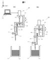
- FIG. 1 is a diagram showing a dispensing device 100 for performing pressure type liquid level detection according to the present disclosure.
- the dispensing device 100 includes a base 101 having an L-shaped overall shape, and a motor 102, which is a driving unit, is provided above the base 101.
- the base 101 is rotatably provided with a screw shaft 104 made of a trapezoidal screw, a ball screw, or the like connected to the rotation shaft of the motor 102 via a coupling 103.
- the screw shaft 104 is provided with a slider 106 through which the screw shaft 104 is passed and a nut 105 screwed with respect to the screw shaft 104.
- the slider 106 is connected to a linear guide 107 provided on the base 101, and each of the nut 105 and the slider 106 is vertically movable or slidable along the direction of the arrow S shown in the figure. .. Further, the slider 106 is configured to be joined to the piston 108 protruding downward and to move up and down without rotating.
- the piston 108 and the piston receiving portion 109 form a pipette mechanism.
- the control computer 116 which is a control unit, and is sequentially stored in the memory thereof.
- a tip 110 is attached to the tip of the piston receiving portion 109 of the pipette mechanism.
- a chip removing portion 111 is provided above the chip 110.
- the chip removing portion 111 is provided with a U-shaped notch or a through hole having a diameter smaller than the diameter of the opening of the chip 110.
- the chip removing portion 111 is always urged upward by a spring material 112 such as a spring connected to the upper end of the chip removing portion 111 and the base 101, and is configured to be movable up and down along the arrow S. ..
- the dispensing apparatus 100 is installed on an automatic stage (not shown) which is freely driven in the horizontal direction and the vertical direction.
- the control computer 116 controls the dispensing motor 102, which is a drive unit, the automatic stage, and the like.
- the piston 108 is driven in the suction or discharge direction, and the pressure value at that time is measured by the pressure sensor 113 while sucking or discharging air. While sucking or discharging air, the entire dispensing device 100 is driven downward in the vertical direction by an automatic stage or the like ((a) in FIG. 1) and comes into contact with the liquid level of the liquid 114 to be dispensed (FIG. 1).
- FIG. 2 is an example of the pressure waveform 200 when the liquid level is detected by the discharge method.
- the pressure waveform 201 is a waveform when a small amount dispensing tip is used.
- the pressure waveform 202 is a waveform when a large-capacity dispensing tip is used.
- the piston drive speed and the drive speed of the automatic stage can be set arbitrarily, but the pressure waveforms of the pressure waveforms 201 and 202 shown here are waveforms measured by the same operating parameters.
- the pressure waveforms of the pressure waveforms 201 and 202 shown here are waveforms measured by the same operating parameters.
- the pressure of atmospheric pressure 204 Before the start of air discharge 203 is the pressure of atmospheric pressure 204.
- the piston 108 starts to move in the discharge direction, and the pressure rises to 206.
- Approximate straight lines 209 and 210 are obtained from the pressure values that begin to contact the liquid 114 to be dispensed from time 207 and change during time 208, respectively.
- the control computer 116 stops the piston 108 and the automatic stage at a time 213 when the pressure thresholds 211, 212, obtained from prior experiments and stored in memory, are exceeded. To control.
- the liquid level information is acquired by the above operation. Further, at time 213, the maximum pressure values 214 and 215 were measured, respectively.
- FIG. 3 is an example of the pressure waveform 300 when the liquid level is detected by the suction method. While driving the piston 108 in the suction direction, the pressure when the dispensing device 100 connected to the automatic stage was driven vertically downward was measured by the pressure sensor 113. Before the start of air suction 301, the pressure is atmospheric pressure 302. The pressure drops to 304 due to the air suction 303, and from time 305, the tip of the tip begins to come into contact with the dispensing liquid 114, and the liquid is sucked into the inside of the tip.
- the pressure waveform 306 is a waveform when a small amount dispensing tip is used.
- the pressure waveform 307 is a waveform when a large-capacity dispensing tip is used.
- the piston drive speed and the drive speed of the automatic stage can be arbitrarily set, but the pressure waveforms of the pressure waveforms 306 and 307 shown here are waveforms measured by the same operating parameters.
- Approximate straight lines 309 and 310 are obtained from the pressure values that change during the time 308, respectively.
- the control computer 116 captures the changes in these pressures, and at the time 313 when the pressure thresholds 311 and 312 obtained in advance and stored in the memory are exceeded, the piston 108 and stop the automatic stage.
- the liquid level information is acquired by the above operation.
- the minimum pressure values measured at 313 are 314 and 315, respectively.
- FIG. 4 is a diagram showing a processing flow S400 of a normal dispensing method.
- the operations S401 to S410 when the dispensing device dispenses will be described with reference to FIG. 4.
- the automatic stage In order to acquire the liquid level height information, the automatic stage is driven and moves vertically downward toward the liquid level. At this time, the piston 108 can arbitrarily set the operation in the suction direction or the discharge direction. When operated in the discharge direction, the pressure value 206 is measured by the pressure sensor 113, and when operated in the suction direction, the pressure value 304 is measured.
- an approximate straight line 209 or 210 is obtained by the pressure changing from the liquid level contact 207.
- an approximate straight line 309 or 310 is obtained by the pressure changing from the liquid level contact time 305.
- the conditions for detecting the liquid level and stopping the piston 108 and the automatic stage are that the pressure threshold obtained from the previous experiment is exceeded and that the slope of the approximate straight line is equal to or more than a certain value.
- the automatic stage to which the dispensing device 100 is attached drives the dispensing device 100 vertically and horizontally and moves it to a predetermined discharge position.
- the above-mentioned discharge method does not suck the sample at the time of detection, so there is no excess liquid remaining in the chip. Further, in the suction method, there is a possibility that the presence or absence of a clot that causes the tip to be clogged during suction can be detected before the start of the dispensing main suction.
- FIG. 5 shows an example of the pressure waveform 500 when a small amount of air is discharged to the liquid.
- the pressure waveform 501 is a waveform when a small amount dispensing tip is used.
- the pressure waveform 502 is a waveform when a large-capacity dispensing tip is used.
- the pressure value 504 is measured by the pressure sensor while the tip of the chip is in contact with the liquid.
- the pressure values 508 and 507 are measured at the piston stop time 506, respectively.
- Approximate straight lines 509 and 510 are obtained from the pressure changes obtained during time 505. As is clear from the figure, since these approximate straight lines have characteristics for each chip type, it is possible to determine the chip type by comparing the pressure value at the time of stopping or the slope of the approximate straight line with the value measured in advance.
- FIG. 6 is an example of the pressure change waveform 600 when a small amount of liquid is sucked.
- the pressure waveform 601 is a waveform when a small amount dispensing tip is used.
- the pressure waveform 602 is a waveform when a large-capacity dispensing tip is used.
- the pressure value 603 is measured by the pressure sensor with the tip of the tip in contact with the liquid. When a small amount of liquid is sucked between the time 604 and the time 605, the pressure values 608 and 607 are measured at the piston stop time 606, respectively.
- Approximate straight lines 609 and 610 are obtained from the pressure changes obtained during time 605. Since these approximate straight lines have characteristics for each chip type, the determination can be made by comparing the pressure value at the time of stopping and the slope of the approximate straight line with the values measured in advance.
- the liquid level detection method using the pressure waveform, and the chip type determination method it is used because of the difference in the characteristics of the pressure waveform, the relationship between the pressure waveform during suction and the suction time, and the like. It is possible to determine the type of chip that is present.
- Example 2 is a chip type determination method using a pressure waveform obtained at the time of liquid level detection.
- a chip type determination flow S700 using the liquid level detection of FIGS. 3 and 7 will be described with reference to S701 to S712, FIGS. 8 and 9.
- the operation processing main body of this chip type determination flow S700 is a control computer 116 or the like, which is a control unit.
- the automatic stage In order to acquire the liquid level height information, the automatic stage is driven and moves vertically downward toward the liquid level. At this time, the piston 108 can arbitrarily set the operation in the suction direction or the discharge direction. When operated in the discharge direction, the pressure value 206 is measured by the pressure sensor 113, and when operated in the suction direction, the pressure value 304 is measured.
- the stop conditions of the piston and the automatic stage are that the pressure threshold value stored in advance is exceeded and that the slope of the approximate straight line is equal to or more than a certain value.
- the piston stops at time 213 and an approximate straight line 210 is obtained from the pressure waveform 202.
- the pressure threshold value and the inclination condition of the approximate straight line related to the liquid level detection operation are set as the parameters of the large-capacity dispensing tip.
- the set pressure threshold value and the inclination condition are set smaller than the conditions of the small amount dispensing tip, so that the time until the liquid level is detected and stopped is shortened. Therefore, the pressure waveform of the small amount dispensing tip has the shape shown in 801. At time 802, the piston stops to obtain an approximate straight line 803.
- the piston of the large-capacity dispensing tip stops at time 313 and an approximate straight line 310 is obtained from the pressure waveform 307.
- the pressure threshold value and the inclination condition of the approximate straight line regarding the liquid level detection operation are set as the parameters of the large-capacity dispensing tip. If the tip for micro-dispensing is used in this state, the set pressure threshold is large, the tilt condition is small, and the setting is set higher than the condition for the tip for micro-dispensing, so the time until the liquid level is detected and stopped is shortened. ..
- the pressure waveform of the small amount dispensing tip has the shape shown in 901. At time 902, the piston stops to obtain an approximate straight line 903.
- the small-volume dispensing tip has a smaller tip inner diameter, so the pressure change per unit time may be large even from the time 313 shown in FIG. I understand. It can be seen that when the same liquid is sucked, the tip with a smaller tip has a larger pressure change, that is, the slope of the approximate straight line is larger. From this, it can be said that chips having different tip diameters have different features in the slope of the obtained approximate straight line.
- the air capacity inside the chip differs depending on the dispensing capacity.
- a chip with a large dispensing capacity has a large internal air capacity in order to suck more liquid. If the amount of air, which is a compressible fluid, is large, the value detected by the pressure sensor will be delayed. Therefore, the smaller the chip capacitance, the larger the slope of the approximate straight line per unit time. That is, it can be seen that the slopes of the approximate straight lines have different characteristics even when the tip diameters are the same.
- the automatic stage to which the dispensing device 100 is attached drives the dispensing device 100 vertically and horizontally and moves it to a predetermined discharge position.
- Examples 1 and 2 are effective determination methods when there is a large difference in chip capacity and chip tip diameter. For example, a chip having a dispensing capacity of 10 microliters and a chip having a dispensing capacity of 20 microliters may not be able to be determined in Examples 1 and 2 because the difference in capacity and tip diameter is small. In such a case, the type of the chip is determined by using the method shown in this embodiment.
- FIG. 10 is an example of the pressure waveform 1000 when the liquid is sucked.
- the pressure waveform 1001 is a pressure waveform when the liquid is excessively sucked in excess of the chip capacity.
- the automatic stage is moved vertically downward to the liquid level stored in advance.
- the liquid is sucked at the suction time 1003, and the suction liquid penetrates into the filter portion at the excessive suction time 1004, and the pressure is reduced.
- the dotted line 1005 in the figure shows a normal pressure waveform.
- FIG. 11 is an operation flow S1100 of this embodiment.
- the chip type determination method will be described below using the flows S1101 to S1108.
- the automatic stage to which the dispensing device 100 is attached drives the dispensing device 100 vertically and horizontally and moves it to a predetermined discharge position.
- a part or all of them may be designed by, for example, an integrated circuit. Needless to say, it may be realized by hardware. That is, all or part of the functions of the processing unit may be realized by, for example, an integrated circuit such as an ASIC (Application Specific Integrated Circuit) or an FPGA (Field Programmable Gate Array) instead of the program.
- ASIC Application Specific Integrated Circuit
- FPGA Field Programmable Gate Array
- Dispensing device 101 Base 102: Motor 103: Coupling 104: Screw shaft 105: Nut 106: Slider 107: Linear guide 108: Piston 109: Piston receiving part 110: Disposable tip 111: Tip removing part 112: Spring material 113: Pressure sensor 114: Liquid to be dispensed 115: Liquid storage 116: Control computer
Landscapes
- Health & Medical Sciences (AREA)
- Chemical & Material Sciences (AREA)
- Engineering & Computer Science (AREA)
- General Health & Medical Sciences (AREA)
- Immunology (AREA)
- Physics & Mathematics (AREA)
- Analytical Chemistry (AREA)
- Biochemistry (AREA)
- Pathology (AREA)
- General Physics & Mathematics (AREA)
- Life Sciences & Earth Sciences (AREA)
- Quality & Reliability (AREA)
- Clinical Laboratory Science (AREA)
- Chemical Kinetics & Catalysis (AREA)
- Human Computer Interaction (AREA)
- Automatic Analysis And Handling Materials Therefor (AREA)
- Sampling And Sample Adjustment (AREA)
Abstract
Description
圧力波形データを取得開始し、液面検知判定の際に基準となる大気圧204および大気圧302を測定し、制御用コンピュータ116のメモリ等に記憶する。
液面高さ情報取得のため、自動ステージを駆動し液面に向かって鉛直下方に移動する。このときピストン108は吸引方向もしくは吐出方向の動作を任意に設定することができる。吐出方向に動作させた際には圧力センサ113で圧力値206が測定され、吸引方向に動作させた際には圧力値304が測定される。
液面接触207、305においてチップ先端が液面に到達、接触する。
吐出方向に動作させた際は液面接触207から変化する圧力により近似直線209もしくは210を得る。吸引方向に動作させた際には液面接触時間305から変化する圧力により近似直線309もしくは310を得る。液面を検知しピストン108および自動ステージが停止する条件は、事前の実験から得られた圧力閾値を超過することおよび近似直線の傾きが一定の値以上となっていることである。
停止した鉛直方向の位置をメモリに記憶する。
ピストン108を吐出方向動作で液面を検知した場合は、分注する液体114の液面から鉛直上方に離脱した位置で、所定量吸引開始位置にピストンを移動する。ピストン108を吸引方向動作で液面を検知した場合は、分注する液体114の液面から鉛直上方に離脱した位置で液面突入時間308の区間に微量吸引した液体を吐出する。そののちピストン108を所定の吸引開始位置に移動する。
設定した所定量を吸引する。
分注装置100が取り付けられた自動ステージによって、鉛直水平に分注装置100を駆動し、所定の吐出位置に移動する。
所定量を吐出する。
圧力波形データを取得開始し、液面検知判定の際に基準となる大気圧204および大気圧302を圧力センサ113で測定し、記憶する。
液面高さ情報取得のため、自動ステージを駆動し液面に向かって鉛直下方に移動する。このときピストン108は吸引方向もしくは吐出方向の動作を任意に設定することができる。吐出方向に動作させた際には圧力センサ113で圧力値206が測定され、吸引方向に動作させた際には圧力値304が測定される。
液面接触207、305においてチップ先端が液面に到達、接触する。
液面検知の際、ピストンおよび自動ステージの停止条件は、あらかじめ記憶した圧力閾値を超過することおよび近似直線の傾きが一定の値以上となっていることである。
S701からS704の液面検知過程で取得した圧力波形を利用する。ピストンを吐出方向に動作させ液面検知をおこなった場合は、近似直線210および803からチップ種類の判定をする。ピストンを吸引方向に動作させ液面検知をおこなった場合は近似直線310および903からチップ種類の判定をする。
分注に不適切なチップが装着されているとしてエラーを通知する。分注量に対し十分な容量を持ったチップが装着されている場合、分注自体は可能である。しかし、チップ内部の空気容量が多いため所要の分注精度を満足できない可能性がある。ここで装着チップのエラーを検出することで、仕様の分注精度を担保することが可能である。
停止した鉛直方向の位置を記憶する。
ピストン108を吐出方向動作で液面を検知した場合は、分注する液体114の液面から鉛直上方に離脱した位置で、所定量吸引開始位置にピストンを移動する。ピストン108を吸引方向動作で液面を検知した場合は、分注する液体114の液面から鉛直上方に離脱した位置で液面突入時間308の区間に微量吸引した液体を吐出する。そののちピストン108を所定の吸引開始位置に移動する。
設定した所定量を吸引する。
分注装置100が取り付けられた自動ステージによって、鉛直水平に分注装置100を駆動し、所定の吐出位置に移動する。
所定量を吐出する。
圧力波形データを取得開始し、基準となる大気圧を測定し記憶する。
分注装置100が接続されている自動ステージを鉛直下向き方向に、あらかじめ記憶されている吸引可能な液面高さまで移動させ、液体の吸引を開始する。
S1101から継続して取得している吸引圧力波形の変化から判定する。吸引における動作パラメータは、各種液体の液体物理定数(粘度、表面張力、比重、接触角)や分注量に基づき、分注試験等により検証された値で設定される。そのため、ある任意の時点での吸引量を算出することは可能である。
吸引動作を停止し、チップ種類の判定を行う。
判定結果に基づき、分注に不適切なチップが装着されているとしてエラーを通知する。
吸引動作を完了する。
分注装置100が取り付けられた自動ステージによって、鉛直水平に分注装置100を駆動し、所定の吐出位置に移動する。
所定量を吐出する。
101:ベース
102:モータ
103:カップリング
104:ネジ軸
105:ナット
106:スライダ
107:リニアガイド
108:ピストン
109:ピストン受け入れ部
110:ディスポーザブルチップ
111:チップ取り外し部
112:ばね材
113:圧力センサ
114:分注する液体
115:液体収納部
116:制御用コンピュータ
Claims (15)
- 液体試料を分注チップで吸引し、吸引した前記液体試料を所定量吐出して分注を行う分注装置であって、
前記分注装置の内圧を測定する圧力センサを備え、前記圧力センサが測定した圧力波形から前記分注チップの種類を判定する、
ことを特徴とする分注装置。 - 請求項1に記載の分注装置であって、
前記圧力波形として、液面検知時の圧力波形を利用して、前記分注チップの種類を判定する、
ことを特徴とする分注装置。 - 請求項2に記載の分注装置であって、
吸引及び吐出を行うピペット機構と、前記ピペット機構を駆動する駆動部と、を備え、
前記ピペット機構に前記分注チップを取り付け、前記駆動部は、前記ピペット機構を吸引もしくは吐出方向に駆動する、
ことを特徴とする分注装置。 - 請求項3に記載の分注装置であって、
前記圧力センサの出力に基づき、前記駆動部を制御する制御部を備える、
ことを特徴とする分注装置。 - 請求項4に記載の分注装置であって、
前記制御部は、前記分注チップの液面到達を検出した際、前記駆動部を停止し、前記分注チップの種類を判定する、
ことを特徴とする分注装置。 - 請求項5に記載の分注装置であって、
前記制御部は、前記分注チップの種類の判定の結果、不適切な分注チップが装着されていると判定した場合、エラー通知を出力する、
ことを特徴とする分注装置。 - 請求項5に記載の分注装置であって、
前記制御部は、前記分注チップの種類の判定の結果、適切な分注チップが装着されていると判定した場合、液面位置を記憶する、
ことを特徴とする分注装置。 - 請求項1に記載の分注装置であって、
前記分注チップとしてフィルタ付き分注チップを用い、
当該フィルタ付き分注チップの仕様容量を超えて液体を吸引した場合に、前記圧力波形から前記分注チップの種類を判定する、
ことを特徴とする分注装置。 - 液体試料を分注チップで吸引し、吸引した前記液体試料を所定量吐出して分注を行う分注装置の分注方法であって、
前記分注装置の内圧を測定し、測定した圧力波形から前記分注チップの種類を判定する、
ことを特徴とする分注方法。 - 請求項9に記載の分注方法であって、
前記圧力波形として、液面検知時の圧力波形を利用して、前記分注チップの種類を判定する、
ことを特徴とする分注方法。 - 請求項10に記載の分注方法であって、
前記分注チップを吸引もしくは吐出方向に駆動する、
ことを特徴とする分注方法。 - 請求項11に記載の分注方法であって、
前記分注チップの液面到達を検出した際、前記駆動を停止し、前記分注チップの種類を判定する、
ことを特徴とする分注方法。 - 請求項12に記載の分注方法であって、
前記分注チップの種類の判定の結果、不適切な分注チップが装着されていると判定した場合、エラー通知を出力する、
ことを特徴とする分注方法。 - 請求項12に記載の分注方法であって、
前記分注チップの種類の判定の結果、適切な分注チップが装着されていると判定した場合、液面位置を記憶する、
ことを特徴とする分注方法。 - 請求項9に記載の分注方法であって、
前記分注チップとしてフィルタ付き分注チップを用い、
当該フィルタ付き分注チップの仕様容量を超えて液体を吸引した場合に、前記圧力波形から前記分注チップの種類を判定する、
ことを特徴とする分注方法。
Priority Applications (6)
| Application Number | Priority Date | Filing Date | Title |
|---|---|---|---|
| JP2022541329A JPWO2022029826A1 (ja) | 2020-08-03 | 2020-08-03 | |
| US18/013,933 US20230314455A1 (en) | 2020-08-03 | 2020-08-03 | Dispensing device and method |
| CN202080104323.9A CN116194217A (zh) | 2020-08-03 | 2020-08-03 | 分注装置以及方法 |
| EP20948592.9A EP4190449A4 (en) | 2020-08-03 | 2020-08-03 | DISTRIBUTION DEVICE AND METHOD |
| KR1020237003741A KR20230034352A (ko) | 2020-08-03 | 2020-08-03 | 분주 장치 및 방법 |
| PCT/JP2020/029640 WO2022029826A1 (ja) | 2020-08-03 | 2020-08-03 | 分注装置、及び方法 |
Applications Claiming Priority (1)
| Application Number | Priority Date | Filing Date | Title |
|---|---|---|---|
| PCT/JP2020/029640 WO2022029826A1 (ja) | 2020-08-03 | 2020-08-03 | 分注装置、及び方法 |
Publications (1)
| Publication Number | Publication Date |
|---|---|
| WO2022029826A1 true WO2022029826A1 (ja) | 2022-02-10 |
Family
ID=80117179
Family Applications (1)
| Application Number | Title | Priority Date | Filing Date |
|---|---|---|---|
| PCT/JP2020/029640 WO2022029826A1 (ja) | 2020-08-03 | 2020-08-03 | 分注装置、及び方法 |
Country Status (6)
| Country | Link |
|---|---|
| US (1) | US20230314455A1 (ja) |
| EP (1) | EP4190449A4 (ja) |
| JP (1) | JPWO2022029826A1 (ja) |
| KR (1) | KR20230034352A (ja) |
| CN (1) | CN116194217A (ja) |
| WO (1) | WO2022029826A1 (ja) |
Citations (4)
| Publication number | Priority date | Publication date | Assignee | Title |
|---|---|---|---|---|
| JPH1194844A (ja) * | 1997-09-25 | 1999-04-09 | Aloka Co Ltd | 自動分注機能を有した分析用装置 |
| JP2006078202A (ja) * | 2004-09-07 | 2006-03-23 | Hitachi Koki Co Ltd | 自動分注装置 |
| JP2006194689A (ja) * | 2005-01-12 | 2006-07-27 | Olympus Corp | 分注装置、液面検出方法および培養処理装置 |
| WO2006123771A1 (ja) * | 2005-05-19 | 2006-11-23 | Universal Bio Research Co., Ltd. | 分注量検出方法および吸液モニタ型分注装置 |
Family Cites Families (7)
| Publication number | Priority date | Publication date | Assignee | Title |
|---|---|---|---|---|
| US4846003A (en) * | 1988-06-08 | 1989-07-11 | Beckman Instruments, Inc. | Acoustic impedance system for pipette tip detection |
| FI90207C (fi) * | 1992-05-04 | 1994-01-10 | Wallac Oy | Pipettilaitteisto |
| US5537880A (en) * | 1995-06-07 | 1996-07-23 | Abbott Laboratories | Automatic pipetting apparatus with leak detection and method of detecting a leak |
| EP2009449A1 (en) * | 2007-06-06 | 2008-12-31 | Hamilton Bonaduz AG | Method of controlling a pipetting process |
| JP5186430B2 (ja) | 2009-04-27 | 2013-04-17 | 日立アロカメディカル株式会社 | 分注装置 |
| JP5984584B2 (ja) * | 2012-08-28 | 2016-09-06 | 株式会社日立ハイテクノロジーズ | 自動分析装置 |
| EP4030170B1 (en) * | 2018-12-18 | 2023-03-01 | Tecan Trading AG | Classifying liquid handling procedures with a neural network |
-
2020
- 2020-08-03 US US18/013,933 patent/US20230314455A1/en active Pending
- 2020-08-03 KR KR1020237003741A patent/KR20230034352A/ko unknown
- 2020-08-03 WO PCT/JP2020/029640 patent/WO2022029826A1/ja active Application Filing
- 2020-08-03 CN CN202080104323.9A patent/CN116194217A/zh active Pending
- 2020-08-03 JP JP2022541329A patent/JPWO2022029826A1/ja active Pending
- 2020-08-03 EP EP20948592.9A patent/EP4190449A4/en active Pending
Patent Citations (4)
| Publication number | Priority date | Publication date | Assignee | Title |
|---|---|---|---|---|
| JPH1194844A (ja) * | 1997-09-25 | 1999-04-09 | Aloka Co Ltd | 自動分注機能を有した分析用装置 |
| JP2006078202A (ja) * | 2004-09-07 | 2006-03-23 | Hitachi Koki Co Ltd | 自動分注装置 |
| JP2006194689A (ja) * | 2005-01-12 | 2006-07-27 | Olympus Corp | 分注装置、液面検出方法および培養処理装置 |
| WO2006123771A1 (ja) * | 2005-05-19 | 2006-11-23 | Universal Bio Research Co., Ltd. | 分注量検出方法および吸液モニタ型分注装置 |
Non-Patent Citations (1)
| Title |
|---|
| See also references of EP4190449A4 * |
Also Published As
| Publication number | Publication date |
|---|---|
| JPWO2022029826A1 (ja) | 2022-02-10 |
| EP4190449A4 (en) | 2024-03-20 |
| KR20230034352A (ko) | 2023-03-09 |
| CN116194217A (zh) | 2023-05-30 |
| US20230314455A1 (en) | 2023-10-05 |
| EP4190449A1 (en) | 2023-06-07 |
Similar Documents
| Publication | Publication Date | Title |
|---|---|---|
| JP5122949B2 (ja) | 分注量検出方法および吸液モニタ型分注装置 | |
| JP5686744B2 (ja) | 自動分析装置 | |
| JP5899075B2 (ja) | 自動分析装置 | |
| JP5093164B2 (ja) | サンプリング機構 | |
| JP6649942B2 (ja) | 自動分析装置 | |
| JP6854292B2 (ja) | 自動分析装置 | |
| WO2007076293A2 (en) | Method for ascertaining interferants in small liquid samples in an automated clinical analyzer | |
| WO2017033910A1 (ja) | 自動分析装置、分注方法、および液面検知方法 | |
| JP2007322285A (ja) | 分注装置 | |
| JP2009058318A (ja) | 自動分析装置 | |
| JP6919535B2 (ja) | 分注装置 | |
| WO2022029826A1 (ja) | 分注装置、及び方法 | |
| JP6607787B2 (ja) | 自動分析装置 | |
| JP2015031586A (ja) | 分析装置及び液体吸引装置 | |
| JP7061686B2 (ja) | 自動分析装置 | |
| JPH02243960A (ja) | 分析装置の分注器操作方式 | |
| JP7417463B2 (ja) | 分注装置、自動分析装置、分注方法 | |
| JP2000266765A (ja) | 自動分析装置 | |
| JPH0324461A (ja) | 自動分析装置 | |
| WO2022259767A1 (ja) | 分注装置、自動分析装置及び分注方法 | |
| JP4363964B2 (ja) | 分注装置 | |
| CN116324422A (zh) | 多点滤波液体液位检测方法和装置 |
Legal Events
| Date | Code | Title | Description |
|---|---|---|---|
| 121 | Ep: the epo has been informed by wipo that ep was designated in this application |
Ref document number: 20948592 Country of ref document: EP Kind code of ref document: A1 |
|
| ENP | Entry into the national phase |
Ref document number: 2022541329 Country of ref document: JP Kind code of ref document: A |
|
| ENP | Entry into the national phase |
Ref document number: 20237003741 Country of ref document: KR Kind code of ref document: A |
|
| WWE | Wipo information: entry into national phase |
Ref document number: 2020948592 Country of ref document: EP |
|
| NENP | Non-entry into the national phase |
Ref country code: DE |
|
| ENP | Entry into the national phase |
Ref document number: 2020948592 Country of ref document: EP Effective date: 20230303 |