EP2000757A2 - Appareil de circuit de réfrigération - Google Patents
Appareil de circuit de réfrigération Download PDFInfo
- Publication number
- EP2000757A2 EP2000757A2 EP08164858A EP08164858A EP2000757A2 EP 2000757 A2 EP2000757 A2 EP 2000757A2 EP 08164858 A EP08164858 A EP 08164858A EP 08164858 A EP08164858 A EP 08164858A EP 2000757 A2 EP2000757 A2 EP 2000757A2
- Authority
- EP
- European Patent Office
- Prior art keywords
- refrigerant
- flow
- heat exchanger
- orifice
- throttle
- Prior art date
- Legal status (The legal status is an assumption and is not a legal conclusion. Google has not performed a legal analysis and makes no representation as to the accuracy of the status listed.)
- Granted
Links
Images


Classifications
-
- F—MECHANICAL ENGINEERING; LIGHTING; HEATING; WEAPONS; BLASTING
- F25—REFRIGERATION OR COOLING; COMBINED HEATING AND REFRIGERATION SYSTEMS; HEAT PUMP SYSTEMS; MANUFACTURE OR STORAGE OF ICE; LIQUEFACTION SOLIDIFICATION OF GASES
- F25B—REFRIGERATION MACHINES, PLANTS OR SYSTEMS; COMBINED HEATING AND REFRIGERATION SYSTEMS; HEAT PUMP SYSTEMS
- F25B13/00—Compression machines, plants or systems, with reversible cycle
-
- F—MECHANICAL ENGINEERING; LIGHTING; HEATING; WEAPONS; BLASTING
- F25—REFRIGERATION OR COOLING; COMBINED HEATING AND REFRIGERATION SYSTEMS; HEAT PUMP SYSTEMS; MANUFACTURE OR STORAGE OF ICE; LIQUEFACTION SOLIDIFICATION OF GASES
- F25B—REFRIGERATION MACHINES, PLANTS OR SYSTEMS; COMBINED HEATING AND REFRIGERATION SYSTEMS; HEAT PUMP SYSTEMS
- F25B41/00—Fluid-circulation arrangements
- F25B41/30—Expansion means; Dispositions thereof
- F25B41/31—Expansion valves
- F25B41/34—Expansion valves with the valve member being actuated by electric means, e.g. by piezoelectric actuators
- F25B41/35—Expansion valves with the valve member being actuated by electric means, e.g. by piezoelectric actuators by rotary motors, e.g. by stepping motors
-
- F—MECHANICAL ENGINEERING; LIGHTING; HEATING; WEAPONS; BLASTING
- F25—REFRIGERATION OR COOLING; COMBINED HEATING AND REFRIGERATION SYSTEMS; HEAT PUMP SYSTEMS; MANUFACTURE OR STORAGE OF ICE; LIQUEFACTION SOLIDIFICATION OF GASES
- F25B—REFRIGERATION MACHINES, PLANTS OR SYSTEMS; COMBINED HEATING AND REFRIGERATION SYSTEMS; HEAT PUMP SYSTEMS
- F25B41/00—Fluid-circulation arrangements
- F25B41/30—Expansion means; Dispositions thereof
- F25B41/39—Dispositions with two or more expansion means arranged in series, i.e. multi-stage expansion, on a refrigerant line leading to the same evaporator
-
- F—MECHANICAL ENGINEERING; LIGHTING; HEATING; WEAPONS; BLASTING
- F25—REFRIGERATION OR COOLING; COMBINED HEATING AND REFRIGERATION SYSTEMS; HEAT PUMP SYSTEMS; MANUFACTURE OR STORAGE OF ICE; LIQUEFACTION SOLIDIFICATION OF GASES
- F25B—REFRIGERATION MACHINES, PLANTS OR SYSTEMS; COMBINED HEATING AND REFRIGERATION SYSTEMS; HEAT PUMP SYSTEMS
- F25B43/00—Arrangements for separating or purifying gases or liquids; Arrangements for vaporising the residuum of liquid refrigerant, e.g. by heat
- F25B43/003—Filters
-
- G—PHYSICS
- G05—CONTROLLING; REGULATING
- G05D—SYSTEMS FOR CONTROLLING OR REGULATING NON-ELECTRIC VARIABLES
- G05D7/00—Control of flow
- G05D7/06—Control of flow characterised by the use of electric means
- G05D7/0617—Control of flow characterised by the use of electric means specially adapted for fluid materials
- G05D7/0629—Control of flow characterised by the use of electric means specially adapted for fluid materials characterised by the type of regulator means
- G05D7/0635—Control of flow characterised by the use of electric means specially adapted for fluid materials characterised by the type of regulator means by action on throttling means
- G05D7/0641—Control of flow characterised by the use of electric means specially adapted for fluid materials characterised by the type of regulator means by action on throttling means using a plurality of throttling means
- G05D7/0647—Control of flow characterised by the use of electric means specially adapted for fluid materials characterised by the type of regulator means by action on throttling means using a plurality of throttling means the plurality of throttling means being arranged in series
-
- F—MECHANICAL ENGINEERING; LIGHTING; HEATING; WEAPONS; BLASTING
- F25—REFRIGERATION OR COOLING; COMBINED HEATING AND REFRIGERATION SYSTEMS; HEAT PUMP SYSTEMS; MANUFACTURE OR STORAGE OF ICE; LIQUEFACTION SOLIDIFICATION OF GASES
- F25B—REFRIGERATION MACHINES, PLANTS OR SYSTEMS; COMBINED HEATING AND REFRIGERATION SYSTEMS; HEAT PUMP SYSTEMS
- F25B2313/00—Compression machines, plants or systems with reversible cycle not otherwise provided for
- F25B2313/023—Compression machines, plants or systems with reversible cycle not otherwise provided for using multiple indoor units
- F25B2313/0234—Compression machines, plants or systems with reversible cycle not otherwise provided for using multiple indoor units in series arrangements
- F25B2313/02341—Compression machines, plants or systems with reversible cycle not otherwise provided for using multiple indoor units in series arrangements during cooling
-
- F—MECHANICAL ENGINEERING; LIGHTING; HEATING; WEAPONS; BLASTING
- F25—REFRIGERATION OR COOLING; COMBINED HEATING AND REFRIGERATION SYSTEMS; HEAT PUMP SYSTEMS; MANUFACTURE OR STORAGE OF ICE; LIQUEFACTION SOLIDIFICATION OF GASES
- F25B—REFRIGERATION MACHINES, PLANTS OR SYSTEMS; COMBINED HEATING AND REFRIGERATION SYSTEMS; HEAT PUMP SYSTEMS
- F25B2313/00—Compression machines, plants or systems with reversible cycle not otherwise provided for
- F25B2313/023—Compression machines, plants or systems with reversible cycle not otherwise provided for using multiple indoor units
- F25B2313/0234—Compression machines, plants or systems with reversible cycle not otherwise provided for using multiple indoor units in series arrangements
- F25B2313/02343—Compression machines, plants or systems with reversible cycle not otherwise provided for using multiple indoor units in series arrangements during dehumidification
-
- F—MECHANICAL ENGINEERING; LIGHTING; HEATING; WEAPONS; BLASTING
- F25—REFRIGERATION OR COOLING; COMBINED HEATING AND REFRIGERATION SYSTEMS; HEAT PUMP SYSTEMS; MANUFACTURE OR STORAGE OF ICE; LIQUEFACTION SOLIDIFICATION OF GASES
- F25B—REFRIGERATION MACHINES, PLANTS OR SYSTEMS; COMBINED HEATING AND REFRIGERATION SYSTEMS; HEAT PUMP SYSTEMS
- F25B2313/00—Compression machines, plants or systems with reversible cycle not otherwise provided for
- F25B2313/023—Compression machines, plants or systems with reversible cycle not otherwise provided for using multiple indoor units
- F25B2313/0234—Compression machines, plants or systems with reversible cycle not otherwise provided for using multiple indoor units in series arrangements
- F25B2313/02344—Compression machines, plants or systems with reversible cycle not otherwise provided for using multiple indoor units in series arrangements during heating
-
- F—MECHANICAL ENGINEERING; LIGHTING; HEATING; WEAPONS; BLASTING
- F25—REFRIGERATION OR COOLING; COMBINED HEATING AND REFRIGERATION SYSTEMS; HEAT PUMP SYSTEMS; MANUFACTURE OR STORAGE OF ICE; LIQUEFACTION SOLIDIFICATION OF GASES
- F25B—REFRIGERATION MACHINES, PLANTS OR SYSTEMS; COMBINED HEATING AND REFRIGERATION SYSTEMS; HEAT PUMP SYSTEMS
- F25B2400/00—General features or devices for refrigeration machines, plants or systems, combined heating and refrigeration systems or heat-pump systems, i.e. not limited to a particular subgroup of F25B
- F25B2400/04—Refrigeration circuit bypassing means
- F25B2400/0411—Refrigeration circuit bypassing means for the expansion valve or capillary tube
-
- F—MECHANICAL ENGINEERING; LIGHTING; HEATING; WEAPONS; BLASTING
- F25—REFRIGERATION OR COOLING; COMBINED HEATING AND REFRIGERATION SYSTEMS; HEAT PUMP SYSTEMS; MANUFACTURE OR STORAGE OF ICE; LIQUEFACTION SOLIDIFICATION OF GASES
- F25B—REFRIGERATION MACHINES, PLANTS OR SYSTEMS; COMBINED HEATING AND REFRIGERATION SYSTEMS; HEAT PUMP SYSTEMS
- F25B2500/00—Problems to be solved
- F25B2500/12—Sound
-
- F—MECHANICAL ENGINEERING; LIGHTING; HEATING; WEAPONS; BLASTING
- F25—REFRIGERATION OR COOLING; COMBINED HEATING AND REFRIGERATION SYSTEMS; HEAT PUMP SYSTEMS; MANUFACTURE OR STORAGE OF ICE; LIQUEFACTION SOLIDIFICATION OF GASES
- F25B—REFRIGERATION MACHINES, PLANTS OR SYSTEMS; COMBINED HEATING AND REFRIGERATION SYSTEMS; HEAT PUMP SYSTEMS
- F25B2500/00—Problems to be solved
- F25B2500/26—Problems to be solved characterised by the startup of the refrigeration cycle
-
- F—MECHANICAL ENGINEERING; LIGHTING; HEATING; WEAPONS; BLASTING
- F25—REFRIGERATION OR COOLING; COMBINED HEATING AND REFRIGERATION SYSTEMS; HEAT PUMP SYSTEMS; MANUFACTURE OR STORAGE OF ICE; LIQUEFACTION SOLIDIFICATION OF GASES
- F25B—REFRIGERATION MACHINES, PLANTS OR SYSTEMS; COMBINED HEATING AND REFRIGERATION SYSTEMS; HEAT PUMP SYSTEMS
- F25B2700/00—Sensing or detecting of parameters; Sensors therefor
- F25B2700/02—Humidity
-
- Y—GENERAL TAGGING OF NEW TECHNOLOGICAL DEVELOPMENTS; GENERAL TAGGING OF CROSS-SECTIONAL TECHNOLOGIES SPANNING OVER SEVERAL SECTIONS OF THE IPC; TECHNICAL SUBJECTS COVERED BY FORMER USPC CROSS-REFERENCE ART COLLECTIONS [XRACs] AND DIGESTS
- Y02—TECHNOLOGIES OR APPLICATIONS FOR MITIGATION OR ADAPTATION AGAINST CLIMATE CHANGE
- Y02B—CLIMATE CHANGE MITIGATION TECHNOLOGIES RELATED TO BUILDINGS, e.g. HOUSING, HOUSE APPLIANCES OR RELATED END-USER APPLICATIONS
- Y02B30/00—Energy efficient heating, ventilation or air conditioning [HVAC]
- Y02B30/70—Efficient control or regulation technologies, e.g. for control of refrigerant flow, motor or heating
Definitions
- the present invention relates to a refrigerating cycle apparatus that has a throttle structure suitable to control a refrigerant flow and that is suitable to control a two-phase refrigerant, and further relates to an air conditioning apparatus that improves temperature and humidity controllability in a cooling or heating operation, reduces refrigerant flow noise, and improves comfort with respect to room temperature and humidity and noise. Further, the present invention relates to a low noise throttle device or a low noise flow controller that has a simple structure and high reliability and reduces fluid flow noise.
- FIG. 97 shows a refrigerant circuit diagram of a conventional air conditioning apparatus shown in Japanese Unexamined Patent Application Publication No. 11-51514
- FIG. 98 shows a sectional view of an ordinary throttle valve provided in FIG. 97 .
- numeral 1 denotes a compressor
- 2 denotes a four-way valve
- 3 denotes an outdoor heat exchanger
- 4 denotes a first flow controller
- 5 denotes a first indoor heat exchanger
- 6 denotes a second flow controller
- 7 denotes a second indoor heat exchanger
- the refrigerant ejected from the compressor 1 passes through the four-way valve 2, is condensed and liquefied in the outdoor heat exchanger 3, is reduced in pressure by a throttle device 11 because the two-way valve 12 of the first flow controller 4 is closed, is evaporated and gasified in the indoor heat exchanger 5, and returns to the compressor 1 again through the four-way valve 2.
- the refrigerant ejected from the compressor 1 passes through the four-way valve 2 inversely to the cooling operation, is condensed and liquefied in the outdoor heat exchanger 5, is reduced in pressure by the main throttle device 11 because the two-way valve 12 of the first flow controller 4 is closed, is evaporated and gasified in the outdoor heat exchanger 3, and returns to the compressor 1 again through the four-way valve 2.
- the main throttle device 11 of the first flow controller 4 is closed, and the first indoor heat exchanger 5 is operated as a condenser, that is, as a reheater and the second indoor heat exchanger 7 is operated as an evaporator by opening the 2-way valve 12 and controlling the flow amount of the refrigerant by the second flow control valve 6.
- the indoor air is heated in the first indoor heat exchanger 5, whereby it is possible to execute a dehumidifying operation in which a decrease in the room temperature is small.
- Japanese Unexamined Patent Application Publication No. 11-51514 discloses such an arrangement that an orifice-like throttle flow path composed of a plurality of cut grooves 31 and a valve disc 17 is disposed in the valve of a valve seat 18 of a second flow control valve 6 of FIG. 98 .
- numeral 16 denotes an electromagnetic coil for moving the valve disc 17
- 31 denotes a plurality of groove-like cut-outs cut in the opening 18 of a pipe acting as the valve seat and forming orifice-like throttle flow paths.
- This countermeasure for the refrigerant flow noise is devised to continuously flow the gas/liquid two-phase refrigerant through the plurality of orifice-like flow paths.
- this arrangement is not effective because the number of flow paths that can be disposed from processing point view is limited and the refrigerant flow noise is increased.
- an additional countermeasure of providing a noise insulating material and a damping material around the second flow controller 6 is required, so that a problem arises in that the cost is increased, and an installation performance and a cycle performance are deteriorated.
- porous members 32 acting as filters are disposed upstream and downstream of a throttle to reduce refrigerant flow noise as shown in the sectional view of FIG. 99 .
- the porous members 32 are disposed at positions separated from a throttle section, so that they cannot continuously supply a gas/liquid two-phase refrigerant effectively to the throttle section, and thus a problem arises in that refrigerant flow noise is increased.
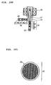
- FIG. 100 shows a sectional view of the arrangement of a flow controller used in an air conditioning apparatus disclosed in Japanese Unexamined Patent Application Publication No. 10-131 681 .
- Honeycomb pipes 37 acting as noise eliminators 36 each having holes communicating both the ends thereof are disposed upstream and downstream of a throttle to reduce refrigerant flow noise.
- FIG. 101 shows a sectional view of the honeycomb pipe.
- An object of the present invention which was made to solve the above problems, is to provide a refrigerating cycle apparatus and an air conditioning apparatus using a throttle device and a flow controller that can greatly reduce refrigerant flow noise and are not clogged by foreign materials in a cycle. Another object of the present invention is to provide a low noise and reliable refrigerating cycle apparatus. Another object of the present invention is to provide a low noise throttle device and flow controller.
- Another object of the present invention is to provide a reliable throttle device and flow controller that are not clogged by foreign materials. Another object of the present invention is to provide a less expensive apparatus having a simple structure. Another object of the present invention is to provide an apparatus that needs not select any particular mounting direction or orientation and has good workability. Another object of the present invention is to provide an easy-to-use air conditioning apparatus.
- Another object of the present invention is to increase the controllability of temperature and humidity in respective cooling, dehumidifying, heating operations in an air conditioning apparatus making use of the heat of condensation in a refrigerating cycle as a heat source for heating the room air to thereby realize a reheating/dehumidifying operation regardless of a cooling season and a heating season.
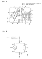
- FIG. 1 is a refrigerant circuit diagram of an air conditioning apparatus showing an example of an embodiment of the present invention, wherein the same components as those of the conventional apparatus are denoted by the same reference numerals.
- numeral 1 denotes a compressor
- 2 denotes a flow-path switching means, for example, a 4-way valve for switching a refrigerant flow between a cooling operation and a heating operation
- 3 denotes an outdoor heat exchanger
- 4 denotes a first flow controller
- 5 denotes a first indoor heat exchanger
- 6 denotes a second flow controller
- 7 denotes a second indoor heat exchanger
- an outdoor unit 33 contains an outdoor fan 40 attached to the outdoor heat exchanger 3
- an indoor unit 34 contains an indoor fan 41 attached to the two indoor heat exchangers.
- a mixed refrigerant R410A composed of R32 mixed with R125 is used as a refrigerant of this refrigerating cycle, and alkylbenzene oil is used as ice machine oil.
- FIG. 2 is a view showing the arrangement of the secondflow controller 6 of the air conditioning apparatus shown in FIG. 1 , wherein numeral 8 denotes a pipe for connecting the first indoor heat exchanger 5 to the second flow controller 6, 11 denotes a throttle device, 12 denotes a two-way valve, 15 denotes a pipe for connecting the second flow controller 6 to the second indoor heat exchanger, 9 denotes a pipe for connecting the pipe 8 to the throttle device 11, 10 denotes a pipe for connecting the pipe 8 to the two-way valve 12, 13 denotes a pipe for connecting the throttle device 11 to a pipe 15, and 14 denotes a pipe for connecting the two-way valve 12 to the pipe 15.
- numeral 8 denotes a pipe for connecting the first indoor heat exchanger 5 to the second flow controller 6
- 11 denotes a throttle device
- 12 denotes a two-way valve
- 15 denotes a pipe for connecting the second flow controller 6 to the second indoor heat exchanger
- 9 denotes a pipe for connecting the pipe
- the second flow controller 6 is composed of the two-way valve 12 connected in parallel to the throttle device 11 through the pipes.
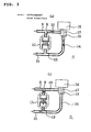
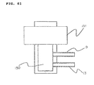
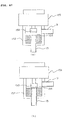
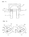
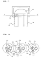
- FIG. 3 depicts sectional views of the second flow controller 6 shown in FIG. 2 showing the operation thereof, wherein (a) shows an operating state of the second flow controller 6 in a cooling operation or a heating operation, and (b) shows an operating state of the second flow controller 6 in a reheating/dehumidifying operation.
- numeral 16 denotes an electromagnetic coil
- 17 denotes a valve disc
- 18 denotes a valve seat.
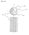
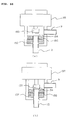
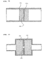
- FIG. 4 is a sectional view in enlargement of the throttle device 11 of the second flow controller 6, wherein 19 denotes an inlet noise eliminating space, 20 denotes a foamed metal disposed on an inlet side, 21 denotes a bypass flow path (through hole) disposed in the inlet side foamed metal, 23 denotes an orifice for performing throttling through a small diameter flow path; 22 denotes a space between the inlet side foamed metal 20 and the orifice 23, 25 denotes an outlet side foamed metal, 24 denotes a space between the orifice 23 and the outlet side foamed metal 25, 26 denotes a bypass flow path (through hole) disposed in the outlet side foamed metal 25, and 27 denotes an outlet side noise eliminating space.
- 19 denotes an inlet noise eliminating space
- 20 denotes a foamed metal disposed on an inlet side
- 21 denotes a bypass flow path (through hole) disposed in the inlet side foamed metal
- Reference numeral 61 denotes a main body with a thickness formed into a cylindrical shape, a polygonal shape, a disc shape, or the like and having the through hole 23 of a small diameter acting as the orifice
- 62 denotes presser members inserted into the main body 61 and having flow paths, for example, pipes for communicating the inside spaces 19 and 26 thereof with the outside.
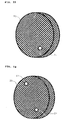
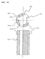
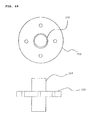
- the foamed metals 20 and 25 as the porous permeable members disposed at the inlet and outlet of the orifice 23 have the same shape, and FIG. 5 shows a sectional view of them in a flow direction.
- Each foamed metal is composed of the porous permeable member in its entirety.
- vent holes ventilation holes on the surface and in the inside of the porous member through which a fluid can pass
- the diameter of the vent holes is set to 500 ⁇ m and the porosity thereof is set to 92 ⁇ 6% in consideration of the influence of clogging.
- bypass flow path 21 (26) defined through the foamed metal 20 (25) is arranged as a through hole located at one position where it is not superimposed on the orifice 2.3 and its diameter is equal to or larger than the minimum diameter of 100 ⁇ m of the vent holes, it can obtain an action as a bypass, and thus reliability can be improved by preventing the occurrence of clogging of the foamed metals.
- a through hole having a diameter of 2 mm is provided.
- the foamed metal is made by coating metal powder or alloy powder on urethane foam, burning and eliminating the urethane foam by subjecting it to a heat treatment, and molding the remaining metal into a three-dimensional lattice shape.
- Ni nickel
- Cr chromium
- the area through which the fluid (refrigerant) passes through the porous permeable members 20 can be largely and effectively utilized by the existence of the predetermined gaps 61c, whereby even if foreign matters are mixed in the fluid (refrigerant), durability to clogging due to foreign matters can be improved. Further, the provision of the positioning projections 61b permits the porous permeable members 20 and the presser members 62 to be positioned easily and reliably, whereby an assembling performance can be improved.
- the ring-shaped positioning projections 61b have an inside diameter set to 10 mm to 20 mm. Further, the inside diameter of the orifice 23 is set to 0.5 mm to 2 mm and the length of the orifice 23 is set to 1 mm to 4 mm; and the dimension of the orifice is determined within the above ranges according to a necessary amount of throttling of the fluid (refrigerant).
- the amount of projection of the positioning projections 61b is set such that the gaps 61c between the porous permeable members 20 and orifice 23 are set within the range of 5 mm or less. In an experiment, a noise reducing effect could be obtained when the gaps 61c were set within the above range.
- the porous permeable members 20 are positioned in the refrigerant (fluid) flow direction by being abutted against the ring-shaped positioning projections 61b. Further, the porous permeable member 20 is fixed in the state in which it is pressed against the ring-shaped positioning projection 61b side by the presser member 62 having the flow path 13 on the surface thereof opposite to that on the orifice 23 side.
- the presser member 62 has the space 19, which has an inside diameter larger than the inside diameter of the flow path 13 and a predetermined length, is inserted into and joined to the main body 61, and also fixes the porous permeable member in place 20.
- the main body 61 and the presser members 62 are made by cutting or forging metal such as copper, brass, aluminum, stainless steel, or the like.
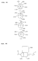
- FIG. 7 shows a block diagram of an overall controller assembled in the air conditioning apparatus.
- the controller 42 is composed of a microprocessor, and the like.
- an operation mode signal for setting an operating state of the air conditioning apparatus a target temperature signal, a target humidity signal, an air flow selecting signal, an operation start/stop signal, and the like are applied to the controller 42 from a remote controller 43 disposed at a location near to, for example, an inhabitant, the controller 42 controls the compressor 1, the 4-way valve 2, the outdoor fan 40, the indoor fan 41, the first flow controller 4, and the second flow controller 6, while monitoring the outputs from a room temperature sensing means 50 and a room humidity sensing means 51.
- Reference numeral 44 denotes a compressor control means for making the operating frequency of the compressor 1 variable
- 45 denotes a 4-way valve control means for switching the 4-way valve 2
- 46 denotes an outdoor fan control means for changing the number of revolutions of the outdoor fan 40
- 47 denotes an indoor/outdoor fan control means for changing the number of revolutions of the indoor fan 40
- 48 denotes a first flow controller control means for controlling the opening/closing of the valve of the first flow controller
- 49 denotes a second flow controller control means for controlling the opening/closing of the valve of the second flow controller.
- FIG. 1 solid arrows show the refrigerant flow in a cooling operation.
- the cooling operation is divided into an ordinary cooling operation corresponding to a case in which both the air conditioning sensible heat load and the air conditioning latent heat load in a room are high at start, in summer, and the like and a dehumidifying operation corresponding to a case in which the latent heat load is large while the air conditioning sensible heat load is low as in an intermediate season, a rainy season, and the like.
- the two-way valve of the second flow controller 6 is put into an open state by the second flow controller control means 49 for controlling the opening/closing of the valve of the second flow controller that receives a command from the controller 42, and the refrigerant is connected from the first indoor heat exchanger to the second indoor heat exchanger with almost no pressure loss.
- a high temperature and high pressure vapor refrigerant ejected from the compressor 1 operating at the number of revolutions corresponding to an air conditioning load passes through the 4-way valve 2, is condensed and liquefied in the outdoor heat exchanger 3, reduced in pressure in the first flow controller 4, and changed to a low pressure two-phase refrigerant, which flows into the first indoor heat exchanger 5 and is evaporated and gasified therein, passes through the second flow controller 6 without a large pressure loss, is evaporated and gasified again in the second indoor heat exchanger 7, and returns to the compressor 1 through the 4-way valve 2 again as a low pressure vapor refrigerant.
- the first flow controller 4 is controlled by the first flow controller control means 48 for controlling the opening and closing of the valve of the first flow controller such that the degree of superheat of the refrigerant at, for example, the intake of the compressor 1 is 10°C.
- heat is drawn from the inside of the room by evaporating the refrigerant in the indoor heat exchanger 5, and the inside of the room is cooled by releasing the heat drawn from the inside of the room to the outside thereof by condensing the refrigerant in the outdoor heat exchanger 3.
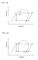
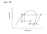
- the high pressure and high temperature vapor refrigerant (point A) ejected from the compressor 1 operating at the number of revolutions corresponding to the air conditioning load passes through the 4-way valve 2, exchanges heat with the outside air in the outdoor heat exchanger 3 and is condensed so as to be made into a condensed gas/liquid two-phase refrigerant (point B).
- the high pressure two-phase refrigerant is somewhat reduced in pressure in the first flow controller 4 and flows into the first indoor heat exchanger 5 as an intermediate pressure gas/liquid two-phase refrigerant (point C).
- the intermediate pressure gas/liquid two-phase refrigerant flowed into the first indoor heat exchanger 5 exchanges heat with the indoor air, and is further condensed (point D).
- the gas/liquid two-phase refrigerant ejected from the first indoor heat exchanger flows into the second flow controller 6.
- the refrigerant flows from the inlet pipe 8 of the second flow controller into the throttle device 11 through the connecting pipe 9.
- the refrigerant from the connecting pipe 9 is reduced in pressure in the orifice 23 through the inlet noise eliminating space 19, the inlet side foamed member 20, and the space 22 between the inlet side foamed member 20 and the orifice 23, and is made into a low pressure gas/liquid two-phase refrigerant, which flows into the second indoor heat exchanger 7 (point E) sequentially passing through the space 24 between the orifice 23 and the outlet side foamed metal 25, the outlet side foamed metal 25, the outlet side noise eliminating space 27, and the connecting pipe 13.
- the thickness in the refrigerant flow direction of the foamed metals disposed at the inlet and the outlet of the orifice be 1 mm or more from the view point of flow noise reduction effect and the processing easiness thereof, and the thickness is set to about 3 mm in this embodiment. Further, the inside diameter of the orifice is set to 1 mm and the thickness thereof is set to about 3 mm.
- the refrigerant having flowed into the second indoor heat exchanger 7 is evaporated by removing the sensible and latent heat of indoor air.
- the low pressure vapor refrigerant ejected from the second indoor heat exchanger returns to the compressor 1 again through the 4-way valve 2. Since the indoor air is heated in the first indoor heat exchanger 5 and cooled and dehumidified in the second indoor heat exchanger 7, it is possible to execute the dehumidification while preventing the reduction in the room temperature.
- the dehumidifying operation it is possible to control a blowing-out temperature in a wide range by controlling the heat exchange amount of the outdoor heat exchanger 3 by adjusting the rotational frequency of the compressor 1 and the number of revolutions of the outdoor fan 40 of the outdoor heat exchanger 3 and by controlling the heating amount of the indoor air heated by the first indoor heat exchanger 5. It is also possible to control the heating amount of the indoor air heated by the first indoor heat exchanger .5 by controlling the condensing temperature of the first indoor heat exchanger by controlling the degree of opening of the first flow controller 4 and the number of revolutions of the indoor fan 41. Further, the second flow controller 6 is controlled such that the degree of superheat of the intake refrigerant of the compressor is set to, for example, 10°C.
- a throttling process is composed of the orifice 23. Since the foamed metals arranged as the porous permeable members are disposed on the inlet side and the outlet side of the orifice 23, and the spaces 19 and 27 capable of obtaining a noise eliminating effect are disposed upstream of the inlet side foamed metal 20 and downstream of the outlet side foamed metal 25, respectively, refrigerant flow noise produced when the gas/liquid two-phase refrigerant passes can be greatly reduced.
- the gas/liquid two-phase refrigerant and the liquid refrigerant flowing into the orifice 23 of the throttle device 11 shown in FIG. 4 are rectified when they pass through the countless number of the fine vent holes of the inlet side foamed member 20.
- vapor slags large bubbles
- a gas and a liquid flow intermittently are made into small bubbles
- the flowing state of the refrigerant is made into a uniform gas/liquid two-phase flow (a state in which a vapor refrigerant and a liquid refrigerant are mixed well). Accordingly, the vapor refrigerant and the liquid refrigerant pass through the orifice 23 at the same time, whereby the speed of the refrigerant is not fluctuated, and the pressure thereof is not also fluctuated.
- the porous permeable member since the flow paths formed inside of the porous permeable member such as the inlet side foamed metal 20 are arranged intricately, the porous permeable member has such an effect that the pressure of the refrigerant is fluctuated repeatedly in the porous member and made constant with a part thereof converted into thermal energy. Thus, even if a pressure fluctuation is caused in the orifice 23, the porous permeable member has an effect of absorbing it and is unlike to transmit the influence of the pressure fluctuation to upstream of the orifice. Further, the flow speed of the refrigerant as a high speed gas/liquid two-phase jet stream downstream of the orifice 23 is sufficiently reduced in the inside of the outlet side foamed metal 25 and uniformly distributed. Accordingly, the high speed gas/liquid two-phase jet stream does not collide against a wall surface and no large swirl is produced in the stream, whereby jet stream noise can be also reduced.
- the inlet noise eliminating space 19 disposed on the inlet side of the throttle device 11 can reduce pressure fluctuations having a low frequency that cannot be suppressed by the inlet side foamed metal 20.
- the outlet noise eliminating space 27 is also disposed on the outlet side of the throttle device 11 likewise, it can reduce pressure fluctuations having a low frequency that cannot be suppressed by the outlet side foamed metal 25.
- the porous permeable member 20 is disposed at a position on an approximate linear line with respect to the inlet inside space 19 and the outlet inside space 27 disposed in an approximate linear state with respect to the refrigerant flow direction in the main body 61.
- the flow state of the refrigerant having passed through the porous permeable member 20 is made into a uniform gas/liquid two-phase flow (a state in which a vapor refrigerant is mixed well with a liquid refrigerant), and further the refrigerant can pass through the throttle path (orifice) 23 while maintaining the uniform gas/liquid two-phase flow (the state in which the vapor refrigerant is mixed well with the liquid refrigerant), whereby the speed of the refrigerant is not fluctuated, the pressure thereof is not also fluctuated, and noise is unlike to be produced.
- the porous permeable member 20 is assembled in such a manner that it is abutted against the positioning projections 61b and then pressed by the presser member 62 so as to be sandwiched between the presser member 62 and the positioning projections 61b.
- the presser member 62 is fixed to the main body 61 by press fitting, shrinkage fit, welding, or the like. Therefore, the porous permeable member 20 can be simply and positively positioned when it is assembled, and thus a less expensive throttle device whose assembly time is reduced and whose reliability is improved can be obtained.
- the structure of the throttle device is simple, it is possible to obtain a throttle device at low cost. Further, a countermeasure, which is required in a conventional apparatus, for winding a noise insulating material and a damping material around a throttle device is not necessary, and thus a less expensive refrigerating cycle apparatus can be obtained.
- the cost can be reduced because the countermeasure required in the convention apparatus for winding the noise insulating material and the damping material around the throttle device 6 is unnecessary, and further the recycling performance of the air conditioning apparatus can be improved.
- the problem of the refrigerant flow noise due to the gas/liquid two-phase refrigerant described above is not limited to the air conditioning apparatus and is a general problem common to general refrigerating cycles such as a refrigerator, and the like, the same effect can be obtained by widely applying the throttle device of this embodiment to these general refrigerating cycles.
- the flow characteristics (the relationship between the flow rate of refrigerant and a pressure loss) of the second flow controller 6 in the cooling/dehumidifying operation can be adjusted by adjusting the diameter of the orifice 23, the length of flow path of the orifice through which the refrigerant passes, and the number of the orifices. That is, when a certain amount of refrigerant is flowed with a small pressure loss, it is sufficient to increase the diameter of the orifice, to decrease the length of the flow path thereof, or to use a plurality of the orifices.
- foamed metal has been described as the element for the porous permeable members used on the outlet and the inlet sides of the orifice in the embodiment, the same effect can be obtained even if ceramics, sintered metal, foamed resin, metal wire netting, and the like are used as the element.
- bypass paths (through holes) 21 and 26 are formed through the inlet side foamed metal 20 and the outlet side foamed metal 25, respectively, at the positions where they are not superimposed on the orifice 23, even if the inlet and outlet side foamed metals 20 and 25 are clogged with foreign materials in the refrigerating cycle, it is possible to prevent the reduction of the performance of the throttle device 11 caused by the clogging.
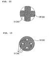
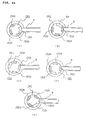
- the space 22 is formed between the inlet side foamed metal 20 and the orifice 23, and the space 24 is formed between the orifice 23 and the outlet side foamed metal 25, almost all the portions of the foamed metals actuate as refrigerant flow paths, whereby a function as the throttle device can be maintained. Since the inlet and outlet side foamed metals 20 and 25 have sufficient reliability as the throttle device, it is possible to provide a sufficiently reliable air conditioning apparatus. While the bypass flow path described in this embodiment is formed into the cylindrical shape and located at one position, the present invention is not limited thereto, and the same effect can be obtained even by a cut-out shaped bypass flow path or a plurality of cylindrical bypass flow paths as shown in FIGS. 12 and 13 .
- FIG. 9 shows the results of measurements of the frequency characteristics of noise produced by a conventional throttle device and those of noise produced by the throttle device of this embodiment.
- the abscissa shows the frequency (Hz) and the ordinate shows the sound pressure (SPL, dBA).
- the dotted line shows the second flow controller of this embodiment, and the solid line shows the conventional second flow controller. It can be found that the sound pressure level of the second flow controller of this embodiment is reduced as compared with the conventional device over the entire frequency range. In particular, it can be found that a great sound pressure level reduction effect can be obtained in the range of from 2000 Hz to 7000 Hz that is well audible to human ears.
- a preset temperature and humidity are set for the air conditioning apparatus when it is operated in order to set a temperature and humidity environment preferred by an inhabitant in a room.
- the inhabitant may directly input the respective set values of the preset temperature and humidity from the remote controller 43 of the indoor unit.
- an optimum temperature and humidity value table which is determined for respective inhabitants who are sensitive to the heat and cold, to children, to elderly persons, and the like, may be stored in the remote controller of the indoor unit so that they can directly input any stored optimum value.
- the indoor unit 34 is provided with sensors for detecting the temperature and humidity of the intake air of the indoor unit to detect the room temperature and humidity.
- the difference between a preset temperature and the current intake air temperature of the room and the difference between a preset humidity and the current intake air humidity of the room are calculated as a temperature difference and a humidity difference, respectively, and the rotational frequency of the compressor 1, the number of revolutions of the outdoor fan, the number of revolutions of the indoor fan, the degree of throttle opening of the first flow control valve 4, and the opening/closing of the second flow control valve 6 of the air conditioning apparatus are controlled such that these differences are finally brought to zero or within the predetermined values.
- the air conditioning apparatus is controlled giving priority to the temperature difference over the humidity difference.
- the controller instructs to set the valve disc 17 of the two-way valve 12 of the second flow control valve 6 at an open position, as shown in FIG. 3(a) . Since the refrigerant passing through the second flow controller has almost no pressure loss, neither the cooling capacity nor the cooling efficiency is reduced. As described above, the second flow controller 6 is set to the open state, and the air conditioning apparatus is operated first such that the temperature difference in the room is preferentially set to zero or within the predetermined value in an ordinary cooling operation.
- the humidity difference is detected.
- the operation of the air conditioning apparatus will be continued as it is.
- the valve disc 17 of the second flow control valve 6 is set to the position where it is in intimate contact with the valve seat 18, as shown in FIG. 3(b) .
- the operation of the air conditioning apparatus is switched to a cooling/dehumidifying operation by throttling the second control valve 12.
- the heating amount of the first indoor heat exchanger 5 is controlled such that the temperature difference in the room can be maintained at zero or within the predetermined value as well as the cooling/ dehumidifying amount of the second indoor heat exchanger 7 is controlled such that the humidity difference is set to zero or within the predetermined value.
- the control of the heating amount of the first indoor heat exchanger 5 is adjusted by the number of revolutions of the outdoor fan of the outdoor heat exchanger 3, the degree of opening of the first flow control valve 4, and the like. Further, the cooling/dehumidifying amount of the second indoor heat exchanger 7 is controlled by the rotational frequency of the compressor 1, the number of revolutions of the indoor fan of the indoor unit 34, and the like.
- alkylbenzene oil that is unlike to be dissolved in the refrigerant is used as ice machine oil in this embodiment, foreign matters that are not dissolved in the refrigerant and foreign materials that are dissolved in the ice machine oil exist in the refrigerating cycle.
- the reliability of the throttle section to clogging can be improved because when these foreign materials are deposited on the foamed metals as the porous permeable members, the ice machine oil that is unlike to be dissolved in the refrigerant has an effect of cleaning the foreign materials when it passes through the foamed metals.
- the heating operation of the air conditioning apparatus of the present invention will be described below.
- the refrigerant circuit constituting the air conditioning apparatus is the same as that shown in, for example, FIG. 1 , so that the arrangement of the second flow controller 6 is the same as that shown in FIG. 3 , and the detailed structure of the throttle device 11 is the same as that shown in FIG. 4 .
- FIG. 1 the flow of the refrigerant in the heating is shown by the broken arrows.
- the controller instructs to set the valve disc 17 of the two-way valve 12 of the second flow control valve 6 in the open position, as shown in FIG. 3(a) .
- the high temperature and high pressure vapor refrigerant ejected from the compressor 1 flows into the second indoor heat exchanger 7 and into the first indoor heat exchanger 5 through the 4-way valve 2, exchanges heat with the indoor air, and is condensed and liquefied.
- the pipe 8 is connected to the pipe 15 through a large opening area as shown in FIG. 3(a) , almost no pressure loss is caused in the refrigerant when it passes through the valve, and thus no decrease in the heating capacity and efficiency is caused by the pressure loss.
- the high pressure liquid refrigerant ejected from the first indoor heat exchanger 5 is reduced in pressure by the first flow controller 4 and made into a gas/liquid two-phase refrigerant, which exchanges heat with the outside air in the outdoor heat exchanger 3 and is evaporated.
- the low pressure vapor refrigerant ejected from the outdoor heat exchanger 3 returns to the compressor 1 again through the 4-way valve 2.
- the degree of opening of the first flow control valve 4 in the ordinary heating operation is controlled such that the degree of superheat of the refrigerant at the outlet of the outdoor heat exchanger 3 is set to, for example, 5°C.
- the controller instructs to cause the valve disc 17 of the two-way valve 12 of the second flow control valve 6 to be in intimate contact with the valve seat 18, as shown in FIG..3(b) .
- the high temperature and pressure vapor refrigerant ejected from the compressor 1 flows into the second indoor heat exchanger 7 through the 4-way valve 2, exchanges heat with the indoor air, and is condensed (point E).
- the high pressure liquid refrigerant or the gas/liquid two-phase refrigerant flows into the second flow control valve 6.
- the valve disc 17 of the two-way valve 12 Since the valve disc 17 of the two-way valve 12 is in intimate contact with the valve seat 18 in the second flow control valve 6 as shown in FIG. 3(b) , the high pressure liquid refrigerant or the gas/liquid two-phase refrigerant flows into the throttle device 11 through the second flow path connecting pipe 13, is reduced in pressure and expanded in the orifice 23, and made into a low pressure gas/liquid two-phase refrigerant, which flows into the first indoor heat exchanger 5 through the pipes 9 and 8 (point D).
- the saturation temperature of the refrigerant flowed into the second indoor heat exchanger 5 is equal to or less than the dew point of the indoor air, and the refrigerant is evaporated by drawing the sensible heat and the latent heat of the indoor air (point C).
- the low pressure gas/liquid two-phase refrigerant ejected from the first indoor heat exchanger 5 flows into the first flow control valve 4, is further reduced in pressure, flows into the outdoor heat exchanger 3, exchanges heat with the outside air, and is evaporated.
- the low pressure vapor refrigerant ejected from the outdoor heat exchanger 4 returns to the compressor 1 again through the 4-way valve 2.
- the heating/dehumidifying operation since the indoor air is heated in the second indoor heat exchanger 7 as well as cooled and dehumidified in the first indoor heat exchanger 5, it is possible to dehumidify the room while heating it. Further, in the heating/dehumidifying operation, it is possible to control a blowing-out air temperature in a wide range by controlling the heat exchange amount of the outdoor heat exchanger 3 by adjusting the rotational frequency of the compressor 1 and the number of revolutions of the fan of the outdoor heat exchanger 3 and by controlling the heating amount of the indoor air heated by the first indoor heat exchanger 5.
- the dehumidifying amount of the indoor air dehumidified by the first indoor heat exchanger 5 by controlling the evaporating temperature of the first indoor heat exchanger 5 by adjusting the degree of opening of the first flow control valve 4 and the number of revolutions of the indoor fan.
- the degree of opening of the second flow control valve 6 is controlled such that the degree of supercooling of the refrigerant at the outlet of the second indoor heat exchanger 7 is set to, for example, 10 °C.
- this embodiment employs the second flow control valve in which the orifice 23 of the throttle device 11 is sandwiched between the foamed metals, which permits the dehumidifying operation during heating as well as can prevent the occurrence of refrigerant flow noise in the heating/dehumidifying operation, whereby a comfortable space can be realized as to a temperature and humidity environment and noise.
- the preset temperature, the preset humidity, the intake air temperature, and the intake humidity have been input to the air conditioning apparatus.
- the air conditioning apparatus carries out a high temperature air blowing-out operation for a predetermined period of time, for example, five minutes at the start of heating and then shifts to the ordinary heating operation. Thereafter, switching between the ordinary heating operation and the heating/dehumidifying operation is controlled according to the temperature difference and the humidity difference in the room.
- the compressor 1 is started by putting the valve disc 17 of the two-way valve 12 or the second flow control valve 6 into a throttled state in which the valve disc 17 comes into intimate contact with the valve seat 18, as shown in FIG. 3(b) .
- the evaporating temperature of the first indoor heat exchanger 5 is controlled to become equal to an intake air temperature by adjusting the number of revolutions of the fan of the outdoor heat exchanger 3, the degree of opening of the first flow control valve 4, and the like such that the cooling and dehumidifying capacity in the first indoor heat exchanger 5 is set to zero.
- the air conditioning apparatus shifts to the ordinary heating operation by setting the second flow control valve 6 in the open state, as shown in FIG. 3(a) .
- the rotational frequency of the compressor 1, the number of revolutions of the indoor fan, and the number of revolutions of the outdoor fan are adjusted such that the temperature difference is set to zero or within the predetermined value.
- the humidity difference is detected.
- the heating/dehumidifying operation is carried out by setting the second flow control valve 6 in the throttled state, as shown in FIG. 3(b) .
- the heating amount of the second indoor heat exchanger 7 is controlled such that the temperature difference in the room can be maintained at zero or within the predetermined value as well as the cooling/dehumidifying amount of the first indoor heat exchanger 5 is controlled such that the humidity difference is set to zero or within the predetermined value.
- the heating amount of the second indoor heat exchanger 7 is controlled by the rotational frequency of the compressor 1, the number of revolutions of the fan of the indoor unit 22, and the like. Further, the control of the cooling/dehumidifying amount of the first indoor heat exchanger 5 is adjusted by the number of revolutions of the fan of the outdoor heat exchanger 3, the degree of opening of the first flow control valve 4, and the like.
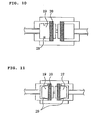
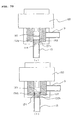
- FIG. 10 is a detailed sectional view showing the structure of another throttle device 11 of the second flow control valve 6 in the air conditioning apparatus of the present invention, wherein the constitutional components that are the same as or similar to those shown in FIG. 4 are denoted by the same reference numerals, and the duplicate description thereof is omitted.
- a convex block 28 is disposed around the inside of the inlet noise eliminating space 19.
- FIG. 11 is a detailed sectional view showing another structure of the throttle device 11 in the second flow control valve 6 of the air conditioning apparatus of the present invention, wherein the constitutional components that are the same as or similar to those shown in FIG. 4 are denoted by the same reference numerals, and the duplicate description thereof is omitted.
- strainers 29 each composed of a woven metal wire are disposed in the inlet and outlet noise eliminating spaces 19 and 27.
- the average pore diameter of the strainers is set smaller than the average pore diameter of 500 micrometers of the inlet and outlet side foamed metals 20 and 25.
- the provision of the strainer 29 composed of the woven metal wire in the inlet noise eliminating space as shown in this embodiment can more reliably prevent the deposit of the foreign materials in the refrigerating cycle on the inlet side foamed metal 20 as compared with the provision of the convex block 28 in the inlet noise eliminating space shown in FIG. 10 .
- the second flow controller having more improved reliability can be obtained, whereby a reliable air conditioning apparatus can be realized.
- R410A is used as the refrigerant of the air conditioning apparatus.
- the refrigerant R410A is an ozone-friendly HFC refrigerant suitable for the conservation of global environment.
- R410A has a smaller pressure loss than that of R22 used conventionally as the refrigerant. This is because it has a larger refrigerant vapor density and thus a slow flow speed.
- R310A is a refrigerant that makes it possible to reduce the size of the vent holes of the porous members used in the throttle device of the second flow control valve 6, whereby a greater refrigerant flow noise reducing effect can be obtained.
- the refrigerant used in the air conditioning apparatus is not limited to R410A, and R407C, R404A, and R507A that are the HFC refrigerants may be used.
- R32 alone, R152a alone, a mixed refrigerant of R32/R124a, and the like that are HFC refrigerants having a small global warming coefficient may be used from the view point of preventing global warming.
- HC refrigerants such as propane, butane, isobutene, etc.
- natural refrigerants such as ammonia, carbon dioxide, ether, and the like, and mixed refrigerants thereof may be used.
- propane, butane, isobutene, and mixed refrigerants thereof have an operating pressure smaller than that of R410A and thus have a small pressure difference between a condensing pressure and an evaporating pressure, which makes it possible to increase the inside diameter of an orifice, thereby reliability to clogging can be more improved.
- the present invention is not limited to the two-way valve, and the second flow controller may use a multidirectional valve, for example, a 3-way valve, by which the same effect can be obtained.
- a method of using the 3-way valve in this case it is possible to include a refrigerant circuit in which a diverted flow path is connected to the outlet side pipe of the second indoor heat exchanger, in addition to the flow path connected in parallel with the throttle device so that the diverted flow path bypasses a refrigerant as a means for reducing the dehumidifying capacity depending upon air conditioning load conditions.
- the refrigerating cycle apparatus of the present invention having the refrigerating cycle in which the compressor, the condenser, the flow controller, and the evaporator are circularly connected, respectively, is provided with the throttle device composed of the multidirectional valve and the orifice connected in parallel with each other, wherein the orifice has the porous permeable members communicating in the refrigerant flow direction in the flow path thereof. Since the gas/liquid two-phase refrigerant is caused to pass through the orifice in this arrangement, there can be obtained an effect of preventing the occurrence of refrigerant flow noise by preventing the breakage of vapor refrigerant slags and refrigerant bubbles to thereby reduce noise and further prevent the clogging due to foreign materials in the cycle.
- the refrigerating cycle apparatus of the present invention includes the orifice in the throttle flow path, an effect of stably adjusting the flow amount of refrigerant can be obtained. Since the refrigerating cycle apparatus is provided with the porous permeable member at least one of upstream and downstream of the orifice in the refrigerant flow direction, there can be obtained an effect of reducing refrigerant flow noise and jet stream noise produced upstream of the orifice by making the size of the vapor slags and the vapor bubbles finer and by making the gas/liquid two-phase refrigerant uniform.
- the pore diameter of the porous permeable members is set to 100 ⁇ m or more, an effect of reducing the refrigerant flow noise and preventing clogging can be obtained. Further, since the thickness of the porous permeable member in the refrigerant flow direction is set to 1 mm or more, an effect of reducing the refrigerant flow noise, preventing the clogging and ensuring a simplified working can be obtained. Further, since at least one through hole having a diameter of at least 100 ⁇ m is formed through each of the porous permeable members, an effect of preventing the clogging and improving reliability can be obtained.
- the refrigerating cycle apparatus of the present invention is provided with the filter disposed at least one of upstream of the porous permeable member disposed upstream of the orifice and downstream of the porous permeable member disposed downstream of the orifice, the clogging of the upstream or downstream side porous permeable member can be prevented, whereby an effect of more improving reliability can be obtained. Since the stagnating portion is disposed upstream of the porous permeable member, the clogging of the upstream side porous permeable member can be prevented, and thus an effect of more improving reliability can be obtained.
- the space is disposed at least one of upstream of the porous permeable member disposed upstream of the orifice and downstream of the porous permeable member disposed downstream of the orifice, there can be obtained an effect of reducing the refrigerant flowing noise produced upstream or downstream of the orifice.
- the refrigerant is composed of the non-azeotropic refrigerant, it is possible to stably control the flow resistance of the refrigerant with low noise and to pass it even if the phase state of the refrigerant changes to various states of a liquid, gas, and two-phase, and thus an effect of stabilizing the refrigerating cycle can be obtained.
- the refrigerant having the vapor density larger than that of R22 is used, an effect of reducing the size of the throttle device can be obtained. Since the refrigerant is composed of the hydrocarbon refrigerant, the inside diameter of the orifice of the throttle section can be increased, and thus an effect of improving reliability can be obtained. Since the multidirectional valve is closed in the reheating/dehumidifying operation, an effect of dehumidifying the room without reducing the room temperature can be obtained.
- the ice machine oil that is easily dissolved in the refrigerant is used, even if foreign matters in the cycle, which are not dissolved in the refrigerant and are dissolved in the ice machine oil, deposit on the porous permeable members, they can be cleaned with the ice machine oil, and thus an effect of improving reliability with respect to clogging can be obtained. Further, since the ice machine oil that is unlike to be dissolved in the refrigerant is used, even if the ice machine oil deposits on the porous permeable members while the compressor is at stop, the deposited ice machine oil can be cleaned with the refrigerant when the compressor is started, and thus an effect of improving reliability can be obtained.
- the second flow controller is composed of the throttle device composed of the multidirectional valve and the orifice connected in parallel with each other, and the orifice has the porous permeable members communicating in the refrigerant flow direction in the flow path thereof.
- the controller for using the throttle device as the refrigerant flow path in the cooling or dehumidifying as well as heating operations there can be obtained an effect of executing comfortable dehumidification while effectively reducing refrigerant flow noise even if the phase state of the refrigerant is changed by the difference of operation modes. Since the controller for using the throttle device as the refrigerant flow path when the heating operation starts is provided, there can be obtained an effect of executing comfortable heating with an enhanced feeling of quick heating by increasing the temperature of blowing-out air.
- the controller for using the throttle section as the refrigerant flow path when the difference between a preset temperature and a room temperature is equal to or larger than a predetermined value in the heating operation is provided, it is possible to blow out high temperature air when the room temperature is sufficiently lower than the preset temperature. Accordingly, there can be obtained an effect of executing comfortable heating without giving a feeling of cold draft.
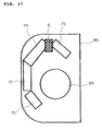
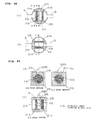
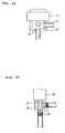
- FIGS. 14 and 15 are front elevational views of an indoor machine, from which a front cover is removed, of the refrigerating cycle apparatus, for example, an air conditioning apparatus, wherein numeral 6 denotes the second flow controller described above, 75 denotes a heat exchanger showing the first indoor heat exchanger 5 or the second indoor heat exchanger 7 disposed in the indoor machine, 74 denotes the controller described in FIG. 7 , 73 denotes a fan motor for driving the fan of the indoor machine, and 88 denotes a cabinet as the outside enclosure of the indoor machine. Further, FIGS. 16 , 17 , and 18 are sectional views of the indoor machine of the air conditioning apparatus.
- 75 denotes the heat exchanger
- 89 denotes a fan
- 88 denotes the cabinet of the indoor machine.
- the throttle device 11 in the second flow controller 6 described in the present invention is disposed in the indoor machine, it can be disposed in the space between the heat exchanger 75 and the fan motor 73, the space between the heat exchanger 75 and the controller 74, and the like in the inside of the cabinet 88 of the indoor machine when viewed at a front position of the cabinet 88, as shown in FIG. 14 .
- the throttle device 11 when viewed at a position on the cross section of the cabinet 88, the throttle device 11 can be disposed on a front surface portion as shown in FIG. 16 , on an upper portion of the cabinet 88 as shown in FIG. 17 , on a rear side of the cabinet as shown in FIG. 18 , and the like. That is, the throttle device of the embodiment can be disposed in any space without the need of any noise insulating material because it operates at low noise. Further, as shown in FIG. 15 , the throttle device 11 can be disposed in the space between the heat exchanger 25 and the cabinet 88. The positions where it can be disposed are the same as those of FIGS. 16 to 18 .
- the throttle device 11 of the present invention operates with low noise, no noise absorbing material is necessary, and thus it can be disposed in any other unused space of the indoor machine of the air conditioning apparatus.
- the throttle device 11 may be disposed in any direction, that is, horizontally, approximately at right angles, obliquely, and the like, with respect to the flow direction of the fluid (refrigerant).
- the fluid (refrigerant) may flow upward from a lower side or downward from an upper side.
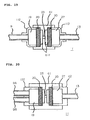
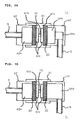
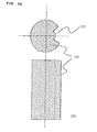
- FIG. 19 is a sectional view of the throttle device 11 showing an example of another structure.
- numeral 112 denotes the presser members 112 which are made by press molding or drawing with the portions thereof connected to pipes being formed by burring. Since the portions of the presser members 112 connected to the pipes 9 and 13 are subjected to the burring, the presser members can be easily made by a press or the like, and thus, the throttle device can be obtained at low cost.
- the throttle device has been mainly described by diving it into the inlet side and the outlet side for the purpose of convenience, the throttle device is also described by using the same material and the same structure by denoting the porous permeable members by 20 and the predetermined space by 61c, for example, in consideration of a case in which the flow of refrigerant is inversed. Further, the expression that the orifice 23 has a function as a flow path or a passage for executing throttling by a small hole is also used.
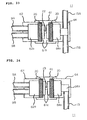
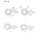
- FIGS. 20 and 21 show sectional views of the throttle device 11 showing examples of another structures.
- numeral 122 denotes presser members to which the pipes 9A and 9B and the pipe 13 acting as flow paths are connected approximately in parallel with the flow direction of the main body 61.
- the pipes 9A and 9B and the pipes 13A and 13B acting as flow paths are connected approximately in parallel with the flow direction of the main body 61.
- the connecting pipes 9 and 13 are connected to the presser members 62 and 112 at each one position of the inlet and the outlet thereof, they may be connected thereto at two positions of the inlets and one position of the outlet as shown in FIG. 20 or at each two positions of the inlets and the outlets as shown in FIG. 21 .
- the pipes 9A, 9B, 13A, and 13B are connected to the spaces 19 and 27 in the insides of the presser members 122 approximately in parallel with the fluid (refrigerant) flow direction in the main body 61, and the throttle path 23 communicates with the pipes 9A, 9B, 13A, and 13B.
- the connecting pipes may be connected from a plurality of positions of two or more positions on both the inlet and outlet sides.
- the porous permeable members 20 are sandwiched between the presser members 62, or the like and the positioning projections 61b and pressed against and fixed to the main body 61 by the presser member 62, or the like in the fluid (refrigerant) flow direction in the main body.
- the heat exchanger has a plurality inlet pipes and outlet pipes, they can be connected to the throttle device 11 of the throttle device 6 as they are, which can reduce a processing and assembling time because it is not necessary to purposely arrange the respective inlet pipes and outlet pipes as a single inlet and outlet, respectively.
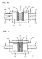
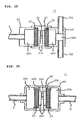
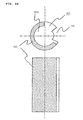
- FIG. 22 is a sectional view showing an example of the throttle device when the predetermined gap 61c is not defined.
- the predetermined gap (the predetermined gap 61c described in FIG. 4 ) is not defined between the orifice 23 and each porous permeable member 20 as shown in FIG. 22 , it is not necessary to provide the positioning projections 61b, and thus a less expensive throttle device can be obtained. Further, while the present invention has been described with reference to the case in which the throttle device 11 is applied to the second flow controller, it is needless to say that the same effect can be obtained even if it is applied to the first flow controller 4.
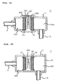
- FIGS. 23, 24 , 25, and 26 are sectional views of the throttle device having another structures, wherein the same components are denoted by the same reference numerals and the description thereof is omitted.
- 20 denotes the porous permeable members
- 61 denotes the main body having the through hole of a small diameter acting as the orifice 23 and formed into, for example, a disc shape or a columnar shape
- 64 denotes the presser members inserted into the main body 61 from the fluid (refrigerant) flow direction side in the main body 61 and having inner spaces 64a and 64b and the flow paths (for example, pipes) 9 and 13 for communicating the inner spaces 64b with the outside.
- the pipes 9 and 13 acting as the flow paths are connected to the inner spaces 64b of the presser members 64 in a direction approximately at right angles to the fluid (refrigerant) flow direction in the main body 61 so as to cause the orifice 23 to communicate with the outside.
- the disposition and arrangement of the second flow controller 6 described with reference to FIGS. 2 to 4 and the disposition and arrangement of the throttle device 6 in the air conditioning apparatus are made flexible, and thus the positions of the throttle device and the pipes can be selected according to the places where they are disposed.
- the dimension of the orifice 23 is determined according to a necessary amount of throttling within the range of an inside diameter of 0.5 mm to 2 mm and a length of 1 mm to 4 mm.
- the positioning projections 61b which are formed into, for example, a ring shape, are disposed in the main body 61 in the fluid (refrigerant) flow direction so as to define the predetermined gaps 61c c between the orifice 23 and the porous permeable members 20.
- the area where the fluid (refrigerant) passes through the porous permeable members 20 can be largely and effectively utilized by the provision of the predetermined gaps 61c, whereby even if foreign matters are mixed in the fluid (refrigerant), durability to clogging due to the foreign matters can be improved.
- the provision of the positioning projections 61b permits the porous permeable members 20 and the presser members 62 to be positioned easily and reliably, and thus an assembling performance can be improved. Further, it is not necessary to separately provide a filter in the refrigerant circuit, and thus a reliable refrigerating cycle apparatus can be obtained at low cost.
- the height of the positioning projections 61b is set such that the inside diameter of the ring-shaped positioning projection 61b is set to 10 mm to 20 mm and the gap 61c between each porous permeable member and the orifice 23 is set to 5 mm or less.
- the porous permeable members 20 are pressed against, inserted into and fixed to the main body 61 by the presser members 64 inserted into the main body 61 from the fluid (refrigerant) flow direction in a manner that they are sandwiched between the positioning projections 61b.
- the porous permeable members 20 have the vent holes whose diameter is set to 100 ⁇ m to 500 ⁇ m and the thickness of 1 mm to 10 mm, and foamed metal composed of Ni, Ni-Cr, or stainless steel is used for the porous permeable members 20. Further, the main body 61 and the presser members 64 are made by cutting or forging metal such as copper, brass, aluminum, stainless steel, or the like.
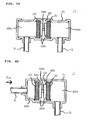
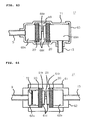
- the inner spaces 64b may be omitted, as shown in FIG. 24 .
- numeral 114 denotes presser members, and the throttle device 11 has such a structure that the pipes 9 and 13 acting as the flow paths directly communicate with inner spaces 64a.
- the inner spaces 64a as shown in FIG. 23 need not be provided, and this permits a processing time to be reduced; whereby a less expensive throttle device can be obtained.
- the flow paths may be formed by burring as shown in FIG. 25 .
- 124 denotes presser members, and the portions thereof connected to the pipes 9 and 13 acting as the flow paths are formed by burring.
- numeral 134 denotes the presser members to which the pipes 9 and 13 acting as the flow paths are connected
- 65 denotes lids.
- cylindrical pipe members are used as the presser members 134 and the lids 15 are joined thereto, commercially available pipes can be used, and thus a less expensive throttle device can be obtained. Further, the same effect can be obtained by the provision of the lids 65 or the pipes 9 and 13.
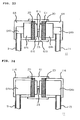
- FIGS. 27 and 28 are sectional views of the throttle device 11 showing examples of another structures.
- 9A, 9B, 13A, and 13B denote the pipes acting as the flow paths
- 64 denotes the presser members to which the pipes 9A to 13B are connected.
- the pipes 13A and 13B are connected to the inner spaces 64b of the presser members 64 approximately at right angles to the fluid (refrigerant) flow direction in the main body 61, and the throttle path 23 communicates with the pipes 9A to 13B.
- the porous permeable members 20 are sandwiched between the presser members 64 and the positioning projections 61b and pressed against and fixed to the main body 61 by the presser members 64 in the fluid (refrigerant) flow direction in the main body.
- the four pipes 9 and 13 are provided in FIG. 27
- the three pipes 9A, 9B, and 13B may be provided, as shown in FIG. 28 .
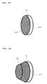
- the porous permeable members 20 are composed of the sintered metal made by sintering metal powder, the porous permeable member composed of ceramics, the metal wiring netting, the member formed by superimposing the plurality of metal wiring nettings, and the sintered metal wire nettings made by sintering the plurality of superimposed metal wire nettings, in addition to the foamed metal.
- the porous permeable members 20 need not be formed into the disc shape, and the same effect can be obtained even if they are formed into the polygonal shape. Further, the same effect can be obtained even if the presser members 64 are formed into the polygonal cylindrical shape instead of the cylindrical shape.
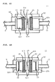
- FIGS. 29, 30 , 31, and 32 are sectional views of the throttle device having another structures, wherein the same components as those described above are denoted by the same reference numerals and the description thereof is omitted.
- 20 denotes the porous permeable members
- 61 denotes the cylindrical main body integral with a disc-shaped plate having the throttle path 23 acting as the orifice
- 62 denotes presser members inserted into the main body 61
- the pipe 9 acting as the flow path is connected to one of the presser members 62 approximately in parallel with the fluid (refrigerant) flow direction in the main body 61
- the pipe 13 is connected to the other of the presser members 64 approximately at right angles to the fluid (refrigerant) flow direction in the main body 61.
- the ring-shaped positioning projections 61b are disposed before and behind the throttle path 23 in the flow direction such that the predetermined gaps 61c are defined between the throttle path 23 and the porous permeable members 20.
- the ring-shaped positioning projections 61b have an inside diameter set to 10 mm to 20 mm.
- the inside diameter of the orifice 23 is set to 0.5 mm to 2 mm, the length thereof is set to 1 mm to 4 mm, and the dimension of the orifice is determined within the above ranges according to a necessary amount of throttling of the fluid (refrigerant).
- the amount of projection of the positioning projections 61b is set such that the gaps 61c between the porous permeable members 20 and the orifice 23 are set within the range of 5 mm or less. In an experiment, a noise reducing effect was obtained when the gaps 61c were set within the above range.
- the porous permeable members 20 are positioned in the fluid (refrigerant) flow direction by being abutted against the ring-shaped positioning projections 61b. Further, the porous permeable members 20 are fixed in the state in which they are pressed against the ring-shaped positioning projection 61b sides by the presser members 62 and 64 having the flow paths 9 and 13 on the surface thereof on the orifice 23 side and the surface thereof on the side opposite to the orifice 23.
- the presser members 62 and 64 have the spaces 62a each having an inside diameter larger than the inside diameter of the flow paths 9 and 13 and a predetermined length, are inserted into and joined to the main body 61, and also fix the porous permeable members in place 20.
- the foamed metal composed of Ni, Ni-Cr, or stainless steel, which has the vent holes whose average diameter is set from about 100 ⁇ m to 500 ⁇ m and has the thickness of about 1 mm to 10 mm, is used for the porous permeable members 20.
- the main body 61 and the presser member 62 are made by cutting or forging metal such as copper, brass, aluminum, stainless steel, or the like.
- the inner space 64b shown in FIG. 29 may be omitted, as shown in FIG. 30 .
- numeral 114 denotes the presser member having such a structure that the pipe 13 acting as the flow path directly communicates with the inner space 64a, which makes the inner space 64b shown in FIG. 29 unnecessary.
- the presser members 112 and 124 shown in FIG. 31 may be used.
- 112 and 124 denote the presser members which are made by press molding or drawing with the portions thereof connected to the pipes 9 and 13 being subjected to burring. Since the portions of the presser members 112 and 124 connected to the pipes 9 and 13 are subjected to the burring, the presser members 112 and 124 can be easily made by a press or the like, and thus a less expensive throttle device can be obtained.
- numeral 112 denotes the presser member to which the pipe 9 acting as the flow path is connected approximately in parallel with the flow direction of the main body
- 134 denotes the presser member to which the pipe 13 acting as the flow path is connected approximately at right angles to the flow direction of the main body
- 65 denotes the lid.
- the lid 65 is joined to the presser member 134 made of a cylindrical pipe, or the like, commercially available pipes can be used, and thus a less expensive throttle device can be obtained. Further, the same effect can be obtained by the provision of the lids 15 on the pipes 9 and 13.
- FIGS. 33, 34 , and 35 are sectional views of the throttle device showing another structures, wherein the same components as those described above are denoted by the same reference numerals and the description thereof is omitted.
- 9A, 9B, 13A, and 13B denote the pipes acting as the flow paths
- 62 denotes the presser members to which the pipes 9A and 9B are connected
- 64 denotes the presser member to which the pipes 13A and 13B are connected.
- the pipes 9A and 9B are connected to the inner space 62a of the presser member 62 approximately in parallel with the fluid (refrigerant) flow direction in the main body 61, the pipes 13A and 13B are connected to the inner space 64b of the presser member 64 approximately at right angles to the fluid (refrigerant) flow direction in the main body 61, and the throttle path 23 communicates with the pipes 9A, 9B, 13A, and 13B.
- the porous permeable members 20 are sandwiched between the presser members 62 and 64 and the positioning projections 61b and pressed against and fixed to the main body 61 by the presser members 62 and 64 in the fluid (refrigerant) flow direction in the main body 61.
- the four pipes 9 and 13 are provided in FIG. 33
- the three pipes 9A, 9B, and 13 may be provided, as shown in FIG. 34 or the three pipes 9, 13A, and 13B may be provided, as shown in FIG. 35 .
- the heat exchanger even if the heat exchanger has a plurality of inlet pipes and outlet pipes, they can be connected to the throttle device 11 as they are, and this can reduce a processing and assembling time because it is not necessary to purposely arrange these pipes as a single pipe.
- the porous permeable members 20 are composed of the sintered metal made by sintering metal powder, the porous permeable member composed of ceramics, the metal wire netting, the members formed by superimposing the plurality of metal wire nettings, and the sintered metal wire netting made by sintering the plurality of superimposed metal wire nettings, in addition to the foamed metal.
- porous permeable members 20 need not be formed into the disc shape, and the same effect can be obtained even if they are formed into the polygonal shape. Further, the same effect can be obtained even if the presser members 62 and 64 and the main body 61 are formed into the polygonal cylindrical shape, or the like in place of the cylindrical shape.
- the flow paths 9 and 13 of the pipes communicating with the two spaces 62a and 64a can be taken out from any of the direction approximately in parallel with the fluid (refrigerant) flow direction in the main body 61 and the direction approximately at right angles thereto. Accordingly, the throttle device can be easily assembled to any of the apparatuses such as the refrigerating cycle apparatus without the need of bending the assembly pipes, and this can reduce an assembly time.
- FIGS. 36 and 37 are sectional views of the throttle device having different structures, which is connected to the refrigerating circuit similar to that described above.
- numeral 20 denotes the porous permeable members
- numeral 68 denotes an orifice component having a throttle path 68a acting as the orifice and formed into, for example, a cylindrical shape, and the porous permeable members 20 are inserted into and fixed to both the sides of the throttle path 68a by press fitting, caulking, or the like.
- the dimension of the orifice 68a is determined according to a necessary amount of throttling within the range of an inside diameter of 0.5 mm to 2 mm and a length of 1 mm to 4 mm.
- the positioning projections 68b formed into, for example, the ring shape are disposed before and behind the throttle path 68a of the orifice component 68 in the fluid (refrigerant) flow direction to define the predetermined gaps 68c between the orifice 68a and the porous permeable members 20.
- the inside diameter of the positioning projections 68b is set to 10 mm to 20 mm, and the height of the positioning projections 68b is set such that the gaps 68c between the porous permeable member 20s and the orifice 68a are set to 5 mm or less.
- the orifice component 68 to which the porous permeable members 20 are fixed integrally therewith is fixed to the main body 69 formed into, for example, a pipe shape by press fitting, shrinkage fit, or the like, and the interior of the main body 69 is divided into two spaces 69a and 69a.
- the ring-shaped positioning projections 68b may be arranged integrally with or separately from the orifice component 68. Accordingly, the orifice 68a and the porous permeable members 20 can be assembled to the main body in a previously assembled state, which improves an assembly performance as well as a reliable apparatus can be obtained.
- flow paths are formed in the main body 69 by drawing both the ends thereof after the orifice component 68 has been inserted into and fixed in the main body 69, and the pipes 9 and 13 are connected to the flow paths approximately in parallel with the fluid (refrigerant) flow direction.
- the spaces between the porous permeable members 20 and the pipes 9 and 13 have a predetermined distance and a predetermined inside diameter.
- a foamed metal composed of Ni, Ni-Cr, or stainless steel, which has the vent holes whose diameter is set from 100 ⁇ m to 500 ⁇ m and has the thickness of 1 mm to 10 mm, is used for the porous permeable members 20.
- the orifice component 68 is made by cutting or forging copper, brass, aluminum, or stainless steel.
- the main body 69 may be drawn as shown in FIG. 37 and the orifice component 68 may be fixed thereto.
- 20 denotes the porous permeable members
- 68 denotes the orifice component having the porous permeable members 20 fixed before and behind the orifice 68a
- 69 denotes the main body made slightly larger than the outside diameter of the orifice component 68.
- the orifice component 68 can be simply inserted into the main body 69 without the need of press fitting or shrinkage fit, which improves the assembling performance as well as reduces the manufacturing time of the throttle device.
- the inlet and outlet of the fluid are disposed at each one position in this structure, it is sufficient that both the inlet and outlet are disposed at least each one position, as described above, and may be disposed at a plurality of positions exceeding one position. Further the inlet and outlet may be disposed in a reverse flow direction.
- FIGS. 38 and 39 are sectional views of different throttle devices that are connected to the refrigerating circuit similar to that described above.
- numeral 20 denotes the porous permeable members
- 68 denotes the orifice component having the throttle path 68a acting as the orifice and formed into, for example, the cylindrical shape, and the porous permeable members 20 are inserted into and fixed to both the sides of the throttle path 68a by press fitting, caulking, or the like.
- the dimension of the orifice 68a is determined according to a necessary amount of throttling within the range of the inside diameter of 0.5 mm to 2 mm and the length of 1 mm to 4 mm.
- the positioning projections 68b formed into, for example, the ring shape are disposed before and behind the throttle path 68a of the orifice component 68 in the fluid (refrigerant) flow direction to define the predetermined gaps 68c between the orifice 68a and the porous permeable members 20.
- the inside diameter of the positioning projections 68b is set to 10 mm to 20 mm, and the height of the positioning projections 68b is set such that the gaps 68c between the porous permeable member 20 and the orifice 68a are set to 5 mm or less.
- the orifice component 68 to which the porous permeable members 20 are fixed integrally therewith, is fixed to a main body 70 formed into, for example, a pipe shape by press fitting, shrinkage fit, or the like.
- the ring-shaped positioning projections 68b may be arranged integrally with or separately from the orifice component 68.
- the lids 65 are airtightly joined to both the ends of the main body 70.
- the flow paths are formed in the main body 70 in a direction approximately at right angles to the fluid (refrigerant) flow direction in the main body 70 by subjecting the main body 70 to burring, and the pipes 9 and 13 are connected to the flow paths at approximately right angles to the fluid (refrigerant) flow direction.
- the spaces between the porous permeable members 20 and the pipes 9 and 13 have a predetermined distance and a predetermined inside diameter.
- the foamed metal composed of Ni, Ni-Cr, or stainless steel, which has the vent holes whose diameter is set from 100 ⁇ m to 500 ⁇ m and has the thickness of 1 mm to 10 mm, is used for the porous permeable members 20.
- the orifice component 68 is made by cutting or forging copper, brass, aluminum, or stainless steel.
- the main body 70 may be drawn and the orifice component 68 may be fixed thereto.
- numeral 20 denotes the porous permeable members
- 68 denotes the orifice component having the porous permeable members 20 fixed before and behind the orifice 68a
- 70 denotes the main body made slightly larger than the outside diameter of the orifice component 68.
- the orifice component 68 can be simply inserted into the main body 70 without the need of press fitting or shrinkage fit, which improves the assembling performance as well as reduces the manufacturing time of the throttle device.
- the inlet and outlet of the fluid are disposed at each one position, it is sufficient that both the inlet and outlet are disposed at least one position, as described above and may be disposed at a plurality of positions exceeding one position. Further the inlet and outlet may be disposed in a reverse flow direction.
- FIGS. 40 , 41 , 42 , and 43 are sectional views of different throttle devices connected to the fluid (refrigerant) circuit similar to that described above.
- numeral 20 denotes the porous permeable members
- 68 denotes the orifice component having the throttle path 68a acting as the orifice and formed into, for example, the cylindrical shape, and the porous permeable members 20 are inserted into and fixed to both the sides of the throttle path 68a by press fitting, caulking, or the like.
- the dimension of the orifice 18a is determined according to a necessary amount of throttling within the range of the inside diameter of 0.5 mm to 2 mm and the length of 1 mm to 4 mm.
- the positioning projections 68b formed into, for example, the ring shape are disposed before and behind the orifice 68a of the orifice component 68 in the fluid (refrigerant) flow direction to define the predetermined gaps 68c between the orifice 68a and the porous permeable members 20.
- the inside diameter of the positioning projections 68b is set to 10 mm to 20 mm, and the height of the positioning projections 68b is set such that the predetermined gaps 68c between the porous permeable members 20 and the orifice 68a are set to 5 mm or less.
- the orifice component 68 to which the porous permeable members 20 are fixed integrally therewith is fixed to a main body 71 formed into, for example, the pipe shape by press fitting, shrinkage fit, or the like.
- the ring-shaped positioning projections 68b may be arranged integrally with or separately from the orifice component 68.
- the main body 71 is drawn in a direction approximately parallel to the fluid (refrigerant) flow direction in the main body, and the pipe 9 acting as the flow path is connected to the main body 71. Further, the main body 71 is closed on the right side thereof in the figure and subjected to burring in a direction approximately at right angles to the fluid (refrigerant) flow direction, and the pipe 13 acting as the flow path is connected to the main body 71.
- the space between the porous permeable member 20 and the pipe 13 has a predetermined distance and inside diameter.
- the foamed metal composed of Ni, Ni-Cr, or stainless steel, which has the vent holes whose diameter is set to 100 ⁇ m to 500 ⁇ m and the thickness of 1 mm to 10 mm, is used for the porous permeable members 20.
- the orifice component 68 is made by cutting or forging copper, brass, aluminum, or stainless steel.
- the positions of the main body 71 corresponding to both the ends of the orifice component 68 may be drawn and the orifice component 68 may be fixed thereto.
- numeral 20 denotes the porous permeable members
- 68 denotes the orifice component having the porous permeable members 20 fixed before and behind the orifice 68a
- 71 denotes the main body made slightly larger than the outside diameter of the orifice component 68.
- the main body 71 is drawn at the positions thereof corresponding to both the ends of the orifice component 68 to thereby fix the orifice component 68 to the main body 71.
- the orifice component 68 can be simply inserted into the main body 71 without the need of press fitting or shrinkage fit, it is possible to improve the assembling performance as well as reduce the manufacturing time of the throttle device. The same effect can be obtained even if the lid 65 is airtightly joined to one end of the main body 71, as shown in FIGS. 42 and 43 .
- the inlet and outlet of the fluid are disposed at each one position, it is sufficient that both the inlet and outlet are disposed at least one position and may be disposed at a plurality of positions or more than one position. Further the inlet and outlet may be disposed in a reverse flow direction.
- the porous permeable members 20 are composed of sintered metal made by sintering metal powder, a porous permeable member composed of ceramics, a metal wire netting, a member formed by superimposing a plurality of metal wire nettings, a sintered metal wire netting obtained by sintering a plurality of superimposed metal wire nettings, in addition to the foamed metal.
- the porous permeable members 20 need not be formed into the disc shape, and the same effect can be obtained even if they are formed into the polygonal shape.
- the same effect can be obtained even if the orifice component 68 and the main body 71 are formed into the polygonal cylindrical shape in place of the cylindrical shape. Further, while the predetermined gaps 61c are defined between the porous permeable members 20 and the orifice 23 or 68a as described above, they need not be defined as already described. With this arrangement, a less expensive throttle device can be obtained because it is not necessary to provide the positioning projections 62b.
- FIGS. 44 , 45 , 46 , 47, and 48 are sectional views of different throttle devices that are arranged such that a filter 72 is provided in the throttle devices described above.
- FIGS. 49, 50 , 51, and 52 are perspective views of the filter 72.
- the same components are denoted by the same reference numerals, and the description thereof is omitted.
- the throttle devices 11 are each connected to the same refrigerant circuit as that described above.
- Reference numeral 72 denotes the filter arranged such that a mesh 72a is fixed to, for example, a ring-shaped fixing component 72b, and the filter 72 is fixed to the inner wall of the presser member 62 of the throttle device 11 by press fitting, as shown in FIG. 44 .
- the mesh 72a of the filter 72 is composed of a metal wire netting, and the like having vent holes whose diameter is smaller than that of the vent holes of the porous permeable members 20.
- the circuit of the refrigerating cycle is arranged similarly to that described above.
- foreign materials when foreign materials are produced in the fluid (refrigerant) flowing through the refrigerating cycle, they are held on the filter 72 when the size thereof is larger than the diameter of the vent holes of the mesh 72a of the filter 72 and do not reach the porous permeable member 20.
- the size of the foreign materials when the size of the foreign materials is smaller than the diameter of the vent holes of the mesh 72a of the filter 72, they pass through the filter 72 and reach the porous permeable member 20.
- the diameter of the vent holes of the porous permeable member 20 is larger than the diameter of the vent holes of the mesh 72a of the filter 72, they also pass through the porous permeable member 20.
- the porous permeable member 20 is not clogged with the foreign material, and thus the durability to clogging is improved. Further, it is possible to prevent the deterioration of performance due to an increase in pressure loss caused by the clogging of the porous permeable members 20, and thus a reliable throttle device can be obtained.
- the porous permeable member 20 is not clogged with foreign material even if a reverse flow direction is used, and thus the durability to clogging is improved.
- the filter 72 has such structure that a fixing extension portion 72c is formed on the fixing component 72b for fixing the mesh 72a, as shown in FIG. 51 , and the fixing extension portion 72c is sandwiched between the presser member 62 and the porous permeable member 20 so as to fix the filter 72 as shown in FIG. 46 . Further, the same effect can be obtained even if the surface area of the filter 72 is increased as shown in FIG. 52 and further the fixing component 72b is provided with the fixing extension portion 72c, and the fixing extension portion 72c is sandwiched between the presser member 62 and the porous permeable member 20 so as to fix the filter 72 as shown in FIG. 47 .
- the filter 72 While one unit of the filter 72 is disposed, a plurality of them may be disposed. Further, while the filter 72 is disposed only on one side of the throttle path 23, it may be disposed to each side thereof as shown in FIG. 48 .
- the filter 72 of the embodiment may be used in any of the throttle devices 11 having been described heretofore, and thus a reliable throttle device and refrigerating cycle apparatus having improved durability to clogging can be obtained.
- the metal wire netting is used as the component constituting the filter 72, the same effect can be obtained even if the filter 72 is composed of the foamed metal, the sintered metal made by sintering metal powder, the porous permeable member composed of ceramics, the member made by superimposing the plurality of metal wire nettings, the sintered metal wire netting made by sintering the several superimposed metal wire nettings, and laminated metal wire nettings.
- FIGS. 53 and 54 are perspective views of the porous permeable member.
- numeral 20 denotes the porous permeable member
- 21 denotes the through hole defined at a position offset from the position of the throttle path 23 in the axial direction thereof.
- a reliable clogging device having an improved durability to clogging can be obtained without losing a function of reducing flow noise by forming the through hole 21 of 1 mm to 3 mm (larger than the inside diameter of the orifice) at one position offset from the throttle path 23 with respect to the flow direction of the porous permeable member 20.
- the through hole 21 is offset from the throttle path 23 with respect to the fluid (refrigerant) flow direction and the porous permeable member 20 exists at the portion where the fluid (refrigerant) easily flows into the throttle path 23, then the durability to clogging of the porous permeable member 20 can be improved without losing the function of reducing flow noise. Further, since the porous permeable member has a large porosity, the fluid (refrigerant) does not concentrate to the through hole 21, and thus the porous permeable member 20 does not lose the above function. Further, the same effect can be obtained even if the through holes 21 are disposed at two positions, as shown in FIG. 54 , or disposed at three positions.
- the refrigerant is used as the fluid used in the refrigerating cycle apparatus and R410A is used as the refrigerant.
- the R410A refrigerant is an ozone-friendly HFC refrigerant suitable for the conservation of global environment as well as has a smaller refrigerant pressure loss as compared with R22 that has been heretofore used as the refrigerant.
- an effect of reducing refrigerant flow noise can be obtained as compared with the case in which the R22 refrigerant is used.
- the refrigerant used in the refrigerating cycle apparatus is not limited to R410A, and R407C, R404A, and R507A that are HFC refrigerants may be used.
- R32 alone, R152a alone, a mixed refrigerant of R32/R134a, and the like as FHC refrigerants having a small global warming coefficient may be used from the view point of preventing global warming.
- HC refrigerants such as propane, butane, isobutene, etc.
- natural refrigerants such as ammonia, carbon dioxide, ether, and the like
- mixed refrigerants made by mixing them may be used.
- the throttle device of the present invention can be applied not only to refrigerating and air conditioning apparatus but also to dehumidifiers having a unit construction evaporator and condenser and a heat exchanger whose interior is partitioned for use and to refrigerators and window air conditioners in which a refrigerating cycle is closed only within a room.
- the throttle device of the present invention is not used only in the refrigerating cycle apparatus but may be used in any apparatus that needs a throttling. Further, any fluid may be used in the throttle device.
- the present invention includes the main body having the two spaces therein that communicate with each other through the throttle path acting as the orifice and are disposed on the approximately linear line with respect to the fluid flow direction, the flow paths for causing the two spaces in the main body to communicate with the outside of the main body, respectively, and the porous permeable member that is fixed in the main body so as to be disposed on the approximately linear line with respect to the two spaces in the main body and partitions at least one of the two spaces to the throttle path side and to the flow path side.
- a fluid in a vapor state and a fluid in a liquid state can simultaneously pass through the throttle path as a uniform gas/liquid two-phase flow, whereby the velocities of the fluids do not fluctuate, a pressure does not also fluctuate, and noise is unlike to be produced.
- the present invention includes the main body having the two spaces therein, which communicate with each other through the throttle path acting as the orifice and are disposed on the approximately linear line with respect to the fluid flow direction, the porous permeable member, which is disposed to cause the fluid to pass in the fluid flow direction in at least one of the two spaces and partitions at least one of the spaces to the throttle path side space and to the opposite side space, the positioning projections, which are interposed between the porous permeable member and the throttle path and position the porous permeable member in the fluid flow direction, and the presser component, which has the flow path disposed to cause the opposite side space to communicate with the outside and is disposed to press the porous permeable member from the opposite side of the throttle path.
- the porous permeable member is positioned by being abutted against the positioning projection. Accordingly, the porous permeable member can be simply and reliably positioned when it is assembled, and an assembly time is reduced, whereby a less expensive throttle device can be obtained.
- the present invention defines the gap between the orifice and the porous permeable member, the area of the porous permeable member through which the fluid passes can be largely and effectively utilized. As a result, even if foreign materials are mixed in the fluid, durability to clogging due to foreign materials is improved and a reliable throttle device can be obtained. Since the orifice integral with the porous permeable member is fixed in the main body such that the throttle path partitions the interior of the main body into the two spaces, the throttle path and the porous permeable member can be assembled to the main body after they are assembled previously, whereby an assembling performance can be improved as well as a reliable throttle device can be obtained.
- the through hole having the diameter larger than that of the throttle path is defined through the porous permeable member at the position offset from the position of the throttle path on the axial line in the flow direction, the durability to clogging of the porous permeable member can be improved without losing the function thereof for reducing flow noise.
- the filter having the mesh whose mesh diameter is smaller than that of the vent holes of the porous permeable member is disposed at the position between the throttle path and the porous permeable member or at the position between the porous permeable member and the flow path, the porous permeable member is not clogged with foreign materials, the durability to clogging is improved and the deterioration of performance due to an increase in pressure loss due to the clogging can be prevented, whereby a reliable throttle device can be obtained. Since two or more flow paths composed of the pipes are disposed in one space, even if a plurality of inlet and outlet pipes are disposed in the heat exchanger, these pipes can be connected to the throttle device as they are.
- the throttle device which includes the main body having the two spaces therein, which communicate with each other through the throttle path acting as the orifice and are disposed on the approximately linear line with respect to the fluid flow direction, the flow path, which causes the two spaces in the main body to communicate with the outside, respectively, and the porous permeable member, which is fixed in the main body so as to be disposed on the approximately linear line with respect to the two spaces in the main body and partitions at least one of the two spaces to the throttle path side and to the flow path side, is disposed in the vicinity of the heat exchanger constituting part of the refrigerating cycle apparatus or in the refrigerating circuit in the room. Accordingly, a countermeasure, which is required in the conventional apparatus, for winding a noise insulating material and a damping material around the throttle device is not necessary, and thus a less expensive and low noise refrigerating cycle apparatus can be obtained.
- the throttle device which includes the main body having the two spaces therein, which communicate with each other through the throttle path and are disposed on the approximately linear line with respect to the flow direction of the refrigerant, the porous permeable member, which is disposed to cause the refrigerant to pass in the refrigerant flow direction in at least one of the two spaces and partitions at least the one space to the throttle path side space and to the opposite side space, the positioning projections, which are interposed between the porous permeable member and the throttle path and form the gap between the porous permeable member and the throttle path, and the presser component, which has the flow path disposed to cause the opposite side space to communicate with the outside and disposed to press the porous permeable member from the opposite side of the throttle path, is disposed in the vicinity of the heat exchanger constituting part of the refrigerating cycle apparatus or in the refrigerating circuit in the room. Accordingly, it is not necessary to separately dispose a filter in the refrigerant circuit, and thus a less expensive, low noise and reliable ref
- the air conditioning apparatus includes the indoor machine, which has the heat exchanger disposed in the cabinet so as to exchange heat with indoor air and the controller disposed in the vicinity of the heat exchanger that is disposed in the cabinet. Then, the throttle device of the present invention is interposed between the heat exchanger and the controller. Accordingly, a less expensive refrigerating cycle apparatus can be obtained which requires no noise insulating material, because the throttle device operates with low noise and can be installed in any place, and in which the throttle device has a large degree of freedom of installation.
- the indoor machine having the heat exchanger disposed in the cabinet for exchanging heat with indoor air is provided, and the throttle device is interposed between the heat exchanger and the controller. Accordingly, a less expensive refrigerating cycle apparatus can be obtained which requires no noise insulating material, because the throttle device operates with low noise and can be installed in any place, and in which the throttle device has a large degree of freedom of installation.
- the structure of the second flow controller has been mainly described with reference to the examples of the throttle device used in parallel with the multi-directional valve and to the applied examples thereof.
- the structure of a throttle device integral with a valve will be described. Accordingly, in the following description, the operation of a refrigerating cycle and the operation and arrangement of an air conditioning apparatus are the same as those of the Embodiment 1 except the portions having specific structures.
- a multi-directional valve is assembled to the throttle device integrally therewith, or it is examined to arrange them more compact so as to obtain a throttle device and a flow controller that are smaller in size and lighter in weight.
- FIG. 55 is a sectional view showing the arrangement of the second flow controller of the air conditioning apparatus shown in FIG. 1 .
- numeral 9 denotes the pipe connected to the first indoor heat exchanger 5 and acts as a refrigerant flow inlet
- 13 denotes the pipe connected to the second indoor heat exchanger 7 and acts as a refrigerant flow outlet
- 150 denotes a main valve body formed into a columnar shape and rotatable in a peripheral direction about the center of a column as an axis while sliding.
- Reference numeral 151 denotes a stepping motor for driving the main valve body 150, and the main valve body 150 is adjusted by driving the stepping motor 151 in response to a command from a controller which is not shown.
- FIG. 56 is a sectional view of the main valve body 150 of the second flow controller 6 shown in FIG. 55 .
- 153 denotes a groove formed in the main valve body 150 and acting as a passing-through flow path through which a refrigerant can pass with almost no flow path resistance applied thereto.
- the main valve body 150 is formed of a porous permeable member in its entirety, and the porous permeable member is composed of sintered metal (hereinafter, referred to as a porous member 152 or a sintered metal) whose vent holes (the vent holes on the surface and inside of the porous member through which a fluid can pass) have an average diameter of 40 micrometers.
- the sintered metal is made by molding metal powder or alloy powder in a mold under pressure and sintering the resultant molded powder at a temperature lower than a melting point.
- the groove 153 formed in the main valve body has a cross sectional area larger than that of the pipe 9 connected to the second flow control valve 6 and the first indoor heat exchanger 5 and that of the pipe 13 connected to the second indoor heat exchanger 7.
- Driving the stepping motor 151 causes the groove 153 of the main valve body to move to the position of the pipe 9 connected to the second flow control valve and the first indoor heat exchanger 5 and to the position of the pipe 13 connected to the second indoor heat exchanger 7, as shown in FIG. 57(b) , and thus the pipes can be connected thereto in a state in which almost no pressure loss is produced. Further, driving the stepping motor 151 in the same way causes the pipe 8 connected to the first indoor heat exchanger 5 to be connected to the pipe 9 connected to the second indoor heat exchanger 7 through the porous member 12 of the main valve body 10.
- solid line arrows show a refrigerant flow in a cooling operation.
- the cooling operation is divided into an ordinary cooling operation corresponding to a case in which both the air conditioning sensible heat load and the air conditioning latent heat load in a room are high at start, in summer, and the like and a dehumidifying operation corresponding to a case in which the latent heat load is large while the air conditioning sensible heat load is low as in an intermediate season, a rainy season, and the like.
- driving the stepping motor 151 of the second flow controller 6 causes the groove 153 of the main valve body 150 to be fixed to the position of the pipe 9 connected to the second flow controller and the first indoor heat exchanger 5 and to the position of the pipe 13 connected to the second indoor heat exchanger 7.
- a high temperature and high pressure vapor refrigerant ejected from the compressor 1 operating at the number of revolutions corresponding to an air conditioning load passes through the 4-way valve 2, is condensed and liquefied in the outdoor heat exchanger 3, reduced in pressure in a first flow controller 4 and made into a low pressure two-phase refrigerant, which flows into the first indoor heat exchanger 5 and is evaporated and gasified therein, passes through the second flow controller 6 without a large pressure loss, is evaporated and gasified again in the second indoor heat exchanger 7, and returns to the compressor 1 through the 4-way valve 2 again as a low pressure vapor refrigerant.
- the groove 153 of the main valve body 150 is located at the position of the pipe 9 connected to the second flow controller and the first indoor heat exchanger 5 and at the position of the pipe 13 connected to the second indoor heat exchanger 7, as shown in FIG. 57(b) .
- the refrigerant passing through the second flow controller has almost no pressure loss, and thus the cooling capacity and efficiency are not reduced.
- the first flow controller is controlled such that the degree of superheat of the refrigerant is set to 10°C at, for example, the intake of the compressor 1.
- the heat is drawn from the inside of a room by evaporating the refrigerant in the first indoor heat exchanger 5, and the room is cooled by releasing the heat drawn from the inside of the room to the outside of the room by condensing the refrigerant in the outdoor heat exchanger 3.
- the dehumidifying operation will be explained using the pressure-enthalpy graph shown in FIG. 6 .
- the controller (not shown) drives the stepping motor of the second flow controller, and the portion of the main valve body 150 other than the groove 153 is located at the position where it is in intimate contact with the end of the pipe 9 connected to the second flow controller and the first indoor heat exchanger 5 and the end of the pipe 13 connected to the second indoor heat exchanger 7, as shown in FIG. 57(a) .
- the high pressure and high temperature vapor refrigerant (point A) ejected from the compressor 1 operating at the number of revolutions corresponding to the air conditioning load passes through the 4-way valve 2, exchanges heat with the outside air in the outdoor heat exchanger 3, and is condensed so as to be made into a condensed gas/liquid two-phase refrigerant (point B).
- the high pressure two-phase refrigerant is somewhat reduced in pressure in the first flow controller 4 and flows into the first indoor heat exchanger 5 as an intermediate pressure gas/liquid two-phase refrigerant (point C).
- the intermediate pressure gas/liquid two-phase refrigerant flowed into the first indoor heat exchanger 5 exchanges heat with the air in the room, and is further condensed (point D).
- the gas/liquid two-phase refrigerant ejected from the first indoor heat exchanger flows into the second flow controller 6.
- the main valve body 150 is located at the position where it is in close contact with the end of the pipe 9 connected to the second flow controller and the first indoor heat exchanger 5 and the end of the pipe 13 connected to the second indoor heat exchanger 7, as shown in FIG. 57(a) , which causes the refrigerant to flow into the second indoor heat exchanger 7 through the vent holes of the porous permeable member constituting the main valve body 150. Since the vent holes of the main valve body 150 have a diameter of about 40 ⁇ m, the refrigerant passing through the vent holes is reduced in pressure and made into a low pressure gas/liquid two-phase refrigerant which flows into the second indoor heat exchanger 7 (point E).
- the refrigerant flowed into the second indoor heat exchanger 7 is evaporated by drawing the sensible and latent heat of the air in the room.
- the low pressure vapor refrigerant ejected from the second indoor heat exchanger returns to the compressor 1 again through the 4-way valve 2. Since the air in the room is heated in the first indoor heat exchanger 5 and cooled and dehumidified by the second indoor heat exchanger 7 it is possible to execute dehumidification while preventing the reduction of a room temperature.
- the heating amount of the air in the room heated by the first indoor heat exchanger 5 by controlling the condensing temperature of the first indoor heat exchanger by controlling the degree of opening of the first flow controller 4 and the number of revolutions of the indoor fan.
- the second flow controller 6 is controlled such that the degree of superheat of the intake refrigerant of the compressor is set to, for example, 10°C.
- refrigerant flow noise produced when the gas/liquid two-phase refrigerant passes through the main valve body 150 can be greatly reduced because it is composed of the sintered metal.
- the gas/liquid two-phase refrigerant passes through an ordinary orifice type flow controller large refrigerant flow noise is produced. It is known that large noise is produced when the gas/liquid two-phase refrigerant flows particularly in a slag flow mode.
- the gas/liquid two-phase refrigerant and the liquid refrigerant pass through an infinite number of fine vent holes of the main valve body 150 composed of the sintered metal and are reduced in pressure. Accordingly, vapor slags and vapor bubbles are not broken. Further, since a vapor refrigerant and a liquid refrigerant simultaneously pass through the throttle section, the speed of the refrigerant is not fluctuated and the pressure thereof is not also fluctuated.
- a conventional orifice has a flow path at one position.
- the pressure of the refrigerant is reduced in the sintered metal.
- a porous member such as the sintered metal has such an effect that the fluctuation of flow speed of the refrigerant is repeated as the pressure fluctuation thereof in the interior of the porous member, and the pressure fluctuation is made constant with a part thereof being converted into thermal energy. This is generally referred to as a noise absorbing effect that is contemplated as a noise eliminating mechanism.
- the flow velocity of the refrigerant is sufficiently reduced in the porous member and made constant, no swirl is produced in the flow of the refrigerant at the outlet of the throttle section, and jet stream noise is also reduced.
- the cost can be reduced because the countermeasure required in the conventional apparatus for winding the noise insulating material and the damping material around the throttle device 6 is not necessary, and further the recycling performance of the air conditioning apparatus can be improved.
- the problem of the refrigerant flow noise due to the gas/liquid two-phase refrigerant described above is not limited to the air conditioning apparatus and is a general problem common to general refrigerating cycles such as a refrigerator, and the like, the same effect can be obtained by widely applying the throttle device of this embodiment to these general refrigerating cycles.
- the flow characteristics of the second flow controller 6 in the cooling/dehumidifying operation can be adjusted by adjusting the diameter of the porous member used in the main valve body 150, the length of the flow path thereof through which the refrigerant passes, and the porosity of the porous member (the volume of pores per unit volume).
- Sintered metal made by molding metal powder or alloy powder in a mold under pressure and sintering the resultant molded powder at a temperature lower than a melting point
- ceramic, foamed metal, foamed resin, and the like are used as the element of the porous member used in the main valve body.
- the main valve body 150 can be driven by the stepping motor 151, even if the main valve body 150 at the inlet of the throttle section is clogged with foreign materials in a cycle, the deterioration of performance of the main valve body 150 due to clogging can be prevented by moving a new surface thereof to the inlet by driving the motor. Further, even if the inlet portion of the porous member of the entire surface of the main valve body is clogged, the groove 153 formed in the main valve body 150 permits the function of the main valve body as the throttle device to be maintained by driving the main valve body 150 with the motor to such position that the inlet of the throttle section partly include the groove. Since the main valve has sufficient reliability as the throttle device, it is possible to provide an air conditioning apparatus having sufficient reliability.
- a preset temperature and humidity are set for the air conditioning apparatus when it is operated in order to set a temperature and humidity environment preferred by an inhabitant in a room.
- the inhabitant may directly input the respective set values of the preset temperature and humidity from a remote controller of an indoor unit.
- an optimum temperature and humidity value table which is determined for respective inhabitants who are sensitive to the heat and cold, children, elderly persons, and the like, may be stored in the remote controller of the indoor unit so that they can directly input any stored optimum values.
- the indoor unit 34 is provided with sensors for detecting the temperature and humidity of the intake air of the indoor unit to detect the room temperature and humidity.
- the difference between a preset temperature and an intake air temperature of the room and the difference between a preset humidity and an intake air humidity of the room are calculated as a temperature difference and a humidity difference, respectively, and the rotational frequency of the compressor 1, the number of revolutions of the outdoor fan, the number of revolutions of the indoor fan, the degree of throttle opening of the first flow control valve 4, and the opening/closing of the second flow control valve 6 of the air conditioning apparatus are controlled such that these differences are finally set to zero or within predetermined values.
- the air conditioning apparatus is controlled giving priority to the temperature difference over the humidity difference.
- a controller instructs the second flow control valve 6 such that the groove 153 of the main valve body 150 is located at the position of the pipe 9 connected to the second flow controller and the first indoor heat exchanger 5 and at the position of the pipe 13 connected to the second indoor heat exchanger 7, as shown in FIG. 57(b) . Since the refrigerant passing through the second flow controller has almost no pressure loss, neither the cooling capacity nor the cooling efficiency is reduced.
- the second flow controller valve 6 is set to the open state, and the air conditioning apparatus is operated first such that the temperature difference in the room is preferentially set to zero or within the predetermined value in an ordinary cooling operation.
- the cooling capacity of the air conditioning apparatus agrees with the heat load of the room and the temperature difference is set to zero or within the predetermined value
- the humidity difference is detected.
- the operation of the air conditioning apparatus will be continued as it is.
- the second flow control valve 6 is located at such a position that the portion of the main valve body 150 other than the groove 153 is in intimate contact with the end of the pipe 9 connected to the second flow controller and the first indoor heat exchanger 5 and with the end of the pipe 13 connected to the second indoor heat exchanger 7, as shown in FIG. 57(a) .
- the operation of the air conditioning apparatus is switched to a cooling/dehumidifying operation by throttling the second flow control valve 6.
- the heating amount of the second indoor heat exchanger 7 is controlled such that the temperature difference in the room can be maintained at zero or within the predetermined value as well as the cooling/dehumidifying amount of the first indoor heat exchanger 5 is controlled such that the humidity difference is set to zero or within the predetermined value.
- the control of the heating amount of the second indoor heat exchanger 7 is adjusted by the number of revolutions of the fan of the outdoor heat exchanger 3, the degree of opening of the first flow control valve 4, and the like. Further, the cooling/dehumidifying amount of the first indoor heat exchanger 5 is controlled by the rotational frequency of the compressor 1, the number of revolutions of the indoor fan 41 of the indoor unit 34, and the like.
- the air conditioning apparatus of the present invention will be described below. This description relates to a heating operation, and a refrigerant circuit constituting the air conditioning apparatus is similar to that of, for example, the Embodiment 1 shown in FIG. 1 , and the structure of the second flow control valve 6 is the same as that shown in FIG. 55 . Operation of the air conditioning apparatus in heating will be described.
- FIG. 1 the flow of the refrigerant in the heating is shown by broken arrows.
- the controller instructs the second flow control valve 6 such that the groove 153 of the main valve body 150 is located at the position of the pipe 9 connected to the second flow controller and the first indoor heat exchanger 5 and at the position of the pipe 13 connected to the second indoor heat exchanger 7, as shown in FIG. 57(b) .
- the high temperature and high pressure refrigerant vapor ejected from the compressor 1 flows into the second indoor heat exchanger 7 and the first indoor heat exchanger 5 through the 4-way valve 2, exchanges heat with the indoor air and is condensed and liquefied.
- the pipe 9 is connected to the pipe 13 through a large opening area as shown in FIG. 57(b) , the refrigerant has almost no pressure loss when it passes through the valve, and thus no decrease in the heating capacity and efficiency is caused by the pressure loss.
- the high pressure liquid refrigerant ejected from the first indoor heat exchanger 5 is reduced in pressure by the first flow controller 4 and made into a gas/liquid two-phase refrigerant, which exchanges heat with the outdoor air in the outdoor heat exchanger 3 and is evaporated.
- the low pressure vapor refrigerant ejected from the outdoor heat exchanger 3 returns to the compressor 1 again through the 4-way valve 2.
- the degree of opening of the first flow control valve 4 in the ordinary cooling operation is controlled such that the degree of superheat of the refrigerant at the outlet of the outdoor heat exchanger 3 is set to, for example, 5°C.
- the controller instructs the second flow control valve 6 such that the main valve body 150 is located at the position where it is in intimate contact with the end of the pipe 9 connected to the second flow controller and the first indoor heat exchanger 5 and at the position where it is in intimate contact with the end of the pipe 13 connected to the second indoor heat exchanger 7, as shown in FIG. 57(a) .
- the high temperature and pressure vapor refrigerant ejected from the compressor 1 flows into the second indoor heat exchanger 7 through the 4-way valve 2, exchanges the heat with indoor air, and is condensed (point E).
- the high pressure liquid refrigerant or the gas/liquid two-phase refrigerant flows into the second flow control valve 6.
- the refrigerant flowed into the valve flows into the first indoor heat exchanger 5 through the vent holes in the main valve body 150 composed of the sintered metal. Since the vent holes of the main valve body 150 have a diameter of about 40 ⁇ m, the refrigerant passing through the vent holes is reduced in pressure and made into an intermediate pressure gas/liquid two-phase refrigerant which flows into the first indoor heat exchanger 5 (point D).
- the saturation temperature of the refrigerant flowed into the first indoor heat exchanger 5 is equal to or less than the dew point temperature of the indoor air, and the refrigerant is evaporated by drawing the sensible heat and the latent heat of the indoor air (point C).
- the intermediate pressure gas/liquid two-phase refrigerant ejected from the first indoor heat exchanger 5 flows into the first flow control valve 4, is reduced in pressure, further flows into the outdoor heat exchanger 3, and exchanges heat with the outdoor air and is evaporated.
- the low pressure vapor refrigerant ejected from the outdoor heat exchanger 4 returns to the compressor 1 again through the 4-way valve 2.
- the heating/dehumidifying operation since the indoor air is heated in the second indoor heat exchanger 7 as well as cooled and dehumidified in the first indoor heat exchanger 5, it is possible to dehumidify the room while heating it. Further, in the heating/dehumidifying operation, it is possible to control a blowing-out air temperature in a wide range by controlling the heat exchange amount of the outdoor heat exchanger 3 by adjusting the rotational frequency of the compressor 1 and the number of revolutions of the fan of the outdoor heat exchanger 3 and by controlling the heating amount of indoor air heated by the first indoor heat exchanger 5.
- the dehumidifying amount of the indoor air dehumidified by the first indoor heat exchanger 5 by controlling the evaporating temperature of the first indoor heat exchanger 5 by adjusting the degree of opening of the first flow controller 4 and the number of revolutions of the indoor fan.
- the degree of opening of the first flow control valve 4 is controlled such that the degree of supercooling of the refrigerant at the outlet of the second indoor heat exchanger 7 is set to, for example, 10 °C.
- this embodiment employs the second flow control valve using sintered metal as the valve main body, which permits the dehumidifying operation when heating is carried out as well as can prevent the occurrence of refrigerant flow noise in the heating/dehumidifying operation, whereby a comfortable space can be realized from the standpoint of temperature and humidity environment and noise.
- the second flow control valve 6 is controlled such that the main valve body 150 is caused to come into intimate contact with the end of the pipe 9 connected to the second flow controller and the first indoor heat exchanger 5 and with the end of the pipe 13 connected to the second indoor heat exchanger 7 and throttled, as shown in FIG. 57(a) , thereby it is possible to increase the temperature of heating blowing-out air. That is, the above heating and dehumidifying cycle is formed at the start of heating, and the evaporating temperature of the first indoor heat exchanger 5 is controlled by the second flow control valve such that it is made approximately the same as the temperature of indoor intake air.
- the evaporating temperature of the first indoor heat exchanger 5 is approximately the same as the temperature of the intake air of the room, almost no cooling and dehumidifying are carried out in the first indoor heat exchanger 5.
- the heat transfer area of the condenser in heating is made about one half that in the ordinary heating operation, and thus a condensing temperature is increased as compared with that in the ordinary heating operation, whereby the blowing-out temperature can be increased.
- no refrigerant flow noise is produced in the second flow control valve 6 and thus no problem is caused from noise point of view.
- the air conditioning apparatus carries out a high temperature air blowing out operation for a predetermined period of time, for example, five minutes at the start of heating and then shifts to the ordinary heating operation. Thereafter, switching between the ordinary heating operation and the heating/dehumidifying operation is controlled according to the temperature difference and the humidity difference of the room.
- the second flow control valve 6 is controlled such that the main valve body 150 is caused to come into intimate contact with the end of the pipe 9 connected to the second flow controller and the first indoor heat exchanger 5 and with the end of the pipe 13 connected to the second indoor heat exchanger 7 and throttled, as shown in FIG. 57(a) ; then the compressor 1 is started.
- the evaporating temperature of the first indoor heat exchanger 5 is controlled to be equal to the intake air temperature by adjusting the number of revolutions of the fan of the outdoor heat exchanger 3, the degree of opening of the first flow control valve 4, and the like such that the cooling and dehumidifying capacity in the first indoor heat exchanger 5 is set to zero.
- the air conditioning apparatus shifts to the ordinary heating operation by setting the second flow control valve 6 to the open state, as shown in FIG. 57(b) .
- the rotational frequency of the compressor 1, the number of revolutions of the indoor fan, and the number of revolutions of the outdoor fan are adjusted such that the temperature difference is set to zero or within a predetermined value.
- the humidity difference is detected.
- the heating/dehumidifying operation is carried out by setting the second flow control valve 6 to the throttled state, as shown in FIG. 57(a) .
- the heating amount of the second indoor heat exchanger 7 is controlled such that the temperature difference in the room can be maintained at zero or within the predetermined value and also the cooling/ dehumidifying amount of the first indoor heat exchanger 5 is controlled such that the humidity difference is set to zero or within the predetermined value.
- the heating amount of the second indoor heat exchanger 7 is controlled by the rotational frequency of the compressor 1, the number of revolutions of the fan of the indoor unit 34, and the like. Further, the control of the cooling/dehumidifying amount of the first indoor heat exchanger 5 is adjusted by the number of revolutions of the fan of the outdoor heat exchanger 3, the degree of opening of the first flow control valve 4, and the like.
- FIG. 58 is a sectional view of the arrangement of the second flow controller of the air conditioning apparatus showing another example thereof
- FIG. 59 is a sectional view of the main valve body 150 of the second flow controller shown in FIG. 58 , wherein the constitutional components that are the same as or similar to those shown in FIGS. 55 and 56 are denoted by the same reference numerals, and the duplicate description thereof is omitted.
- the main valve body 150 is arranged such that the porous member 152 is assembled to a core portion 150a of resin or metal that is ordinarily used.
- Driving the stepping motor 151 in response to a command from the controller (not shown) causes the main valve body 150 to be located at the position shown in FIG. 60(a) , whereby the pipe 9 connected to the first indoor heat exchanger 5 can be connected to the pipe 13 connected to the second indoor heat exchanger 7 with almost no pressure loss through the groove 153 of the main valve body.
- driving the stepping motor 151 in the same way causes the porous member 152 of the main valve body 150 to face the pipe 98 connected to the first indoor heat exchanger 5 and the pipe 13 connected to the second indoor heat exchanger 7 at the position of the porous member 152c, as shown in FIG. 60(c) , whereby these pipes are connected to each other through the vent holes.
- Driving the stepping motor 151 in the same way causes the shut-off portion 150d of the main valve body 150 to face the pipe 9 connected to the first indoor heat exchanger 5 and the pipe 13 connected to the second indoor heat exchanger 7, as shown in FIG. 60(d) , whereby the shut-off portion 150d shuts off the flow path.
- the second flow controller 6 in which no refrigerant flow noise is produced can be obtained at a less expensive material cost by molding a part of the main valve body 150 of the sintered metal as shown in this embodiment rather than molding the overall main valve body 150 of the sintered metal as shown in FIG. 56 .
- the core portion 150a prevents the groove 153 from communicating with the porous permeable member 152. Accordingly, the refrigerant does not flow into the porous permeable member 152 in the open state shown in FIG. 60(a) , and thus the durability of the porous permeable member 152 can be improved.
- the compressor 1 when the compressor 1 is intermittently operated such as when it is repeatedly started and stopped in a case such that the air conditioning load is smaller than the capacity of the compressor 1 of the air conditioning apparatus even if the number of revolutions thereof is minimized, the pressure in the outdoor heat exchanger 3 and the pressure in the indoor heat exchanger 5 are kept in the state during operation when the compressor is stopped by totally closing the pipes 9 and 13 by causing the shut-off portion 150d having a resin or metal surface similarly to the main valve body 150 to face the pipes as shown in FIG. 60 (d) and the starting-up performance of the compressor 1 is improved when it is started next, whereby energy saving operation can be realized.
- FIG. 61 is a sectional view of the arrangement of the second flow controller of the air conditioning apparatus showing another example of the present invention
- FIG. 62 is a sectional view of the main valve body 150 of the second flow controller showing another example of the present invention, wherein the constitutional components that are the same as or similar to those shown in FIGS. 5.5 and 56 are denoted by the same reference numerals, and the duplicate description thereof is omitted.
- the main valve 15 is arranged such that sintered metal is assembled to ordinarily used resin or metal so that the thickness thereof is continuously increased with respect to the center of a valve disc.
- Driving the stepping motor 151 in response to a command from the controller (not shown) causes the groove 153 of the main valve body 150 to be located at a position where a connecting flow path for connecting the pipe 9 connected to the first indoor heat exchanger 5 to the pipe 13 connected to the second indoor heat exchanger 7 is formed, as shown in FIG. 63(a) . In this state, they can be connected to each other with almost no pressure loss.
- driving the stepping motor 151 in the same way causes the porous member 152 of the main valve body 150 to be located at the position where the pipe 9 connected to the first indoor heat exchanger 5 and the pipe 13 connected to the second indoor heat exchanger 7 face the thick wall portion 152c of the porous member 152 having a small flow resistance, as shown in FIG. 63(c) to thereby connect them through the vent holes. Further, driving the stepping motor 151 causes the shut-off portion 150d of the main valve body 150 to face the pipe 9 connected to the first indoor heat exchanger 5 and the pipe 13 connected to the second indoor heat exchanger 7, as shown in FIG. 152(d), and thus a refrigerant flow path is shut off.
- the second flow controller 6 in which no refrigerant flow noise is produced can be obtained at a less expensive material cost by molding a part of the main valve body 150 of the sintered metal as shown in this structure rather than molding the whole main valve body 150 of the sintered metal as shown in FIG. 56 .
- the pressure difference between the first indoor heat exchanger 5 and the second indoor heat exchanger 7 can be adjusted by moving the valve disc by the stepping motor 151 of the second flow controller 6 to operate the refrigerating cycle most effectively.
- Continuously forming the sintered metal permits the main valve body 150 to be processed simply. Further, the main valve body 150 can be reduced in size because the portion where the porous member 152 directly faces the pipes 9 and 13 and the portion in the vicinity thereof can be arranged as a flow path.
- FIG. 64 is a sectional view of the arrangement of the second flow controller of the air conditioning apparatus
- FIG. 65 is a sectional view of the main valve body 150 of the second flow controller, wherein the constitutional components that are the same as or similar to those shown in FIGS. 55 and 56 are denoted by the same reference numerals, and the duplicate description thereof is omitted.
- the core portion 150a of the main valve body 150 is composed of ordinarily used resin or metal, and three types of porous members 152d, 152e, and 152f composed of sintered metal and having vent holes with different average diameters are assembled and disposed in the core portion 150a in the order of the flow resistances thereof; the respective porous members are partitioned from each other by partitions 150b composed of the same material as that of the core portion 150a.
- Driving the stepping motor 151 in response to a command from the controller (not shown) causes the groove 153 of the main valve body 150 to be connected to the pipe 9 connected to the first indoor heat exchanger 5 and to the pipe 13 connected to the second indoor heat exchanger 7 with almost no pressure loss, as shown in FIG. 66(a) .
- Driving the stepping motor 151 in the same way causes the porous member 152d, having a small flow resistance, of the main valve body 150 to face the pipe 9 connected to the first indoor heat exchanger 5 and the pipe 13 connected to the second indoor heat exchanger 7, as shown in FIG. 66(b) to thereby connect them through the vent holes.
- Driving the stepping motor 151 in the same way causes the porous member 152e having an intermediate flow resistance to face the pipe 9 connected to the first indoor heat exchanger 5 and the pipe 13 connected to the second indoor heat exchanger 7, as shown in FIG. 66(c) to thereby connect them through the vent holes.
- Driving the stepping motor 151 in the same way causes the porous member 152c having a large flow resistance to face the pipe 9 connected to the first indoor heat exchanger 5 and the pipe 13 connected to the second indoor heat exchanger 7, as shown in FIG. 66(d) to thereby connect them through the vent holes.
- the second flow controller 6 in which no refrigerant flow noise is produced can be obtained with easy processing at a less expensive material cost by forming the main valve body 150 by assembling the three types of sintered metals whose vent holes have the different average diameters to the ordinarily used resin or metal at the three positions of the main valve body 150 as shown in FIG. 65 rather than molding the main valve body 150 by assembling the sintered metal to the ordinarily used resin or metal such that the thickness of the sintered metal is continuously increased with respect to the center of the valve disc as shown in FIG. 61 .
- the cross sectional areas of the flow paths of the plurality of porous members 152 can be precisely partitioned from each other by partitioning them by the partitions 150b, and thus the flow rate can be controlled precisely.
- the refrigerant can be prevented from flowing into the porous member having the small flow resistance by partitioning the porous members each having the different flow resistance by the partitions 150d as in this embodiment.
- FIG. 67 is a sectional view of the arrangement of the second flow controller 6 of the air conditioning apparatus of the present invention, wherein the constitutional components that are the same as or similar to those shown in FIG. 55 are denoted by the same reference numerals, and the duplicate description thereof is omitted.
- the main valve body 150 is composed of the ordinarily used resin or metal, and the space of the refrigerant flow path formed by the main valve body 150 and a valve seat 154 in a valve chamber is filled with the porous member 152 formed into a columnar shape.
- the sintered metal has vent holes whose average diameter is 0.5 ⁇ m to 200 ⁇ m.
- the valve seat 154 forms a communication port for causing the porous member 152 in the periphery thereof to communicate with the pipe 13 on the pipe 13 side in the valve chamber.
- Deenergizing an electromagnetic coil 155 causes the main valve body 150 to be separated from the valve seat 154, and thus the pipe 9 connected to the first indoor heat exchanger 5 can be connected to the pipe 13 connected to the second indoor heat exchanger 7 with almost no pressure loss because they are connected to each other through a large opening area, as shown in FIG. 67(a) . Further, when the electromagnetic coil 155 is energized, the pipe 9 connected to the first indoor heat exchanger 5 and the pipe 13 connected to the second indoor heat exchanger 7 are connected to the throttle flow path of the porous member 152 of the sintered metal, which is formed by causing the main valve body 150 to come into intimate contact with the valve seat 154, through the vent holes of the porous member 152, as shown in FIG. 67(b) .
- a low noise throttle device can be realized at lower cost as compared with the throttle device using the stepping motor because the main valve body 150 is driven by the electromagnetic coil 155. Since the porous member is formed into the columnar shape, it can be easily processed. Further, the durability to clogging of the porous member is greatly improved because the refrigerant inlet of the porous member can be increased in size. While the porous member is formed into the columnar shape in this embodiment, it is sufficient to form the porous member into any shape formed according to the space formed by the main valve body 150 and the valve seat 154.
- FIG. 68 is a sectional view of the arrangement of the second flow controller 6 of the air conditioning apparatus of the present invention, wherein the constitutional components that are the same as or similar to those shown in FIG. 55 are denoted by the same reference numerals, and the duplicate description thereof is omitted.
- FIG. 69 is a detailed view of the orifices 156 used in the flow controller.
- the main valve body 150 and the valve seat 154 are formed of the ordinarily used resin or metal, and the main valve body 150 is moved in a vertical direction in the valve chamber by energizing and deenergizing the electromagnetic coil 155.
- the refrigerant flow path that reaches the pipe 13 bypassing the valve seat 154 is formed around the columnar valve seat 154 in the valve chamber formed by the main valve body 150 and the valve seat 154.
- the porous members 152 composed of the sintered metal whose vent holes have a diameter of from 100 ⁇ m to 500 ⁇ m are uniformly disposed in the refrigerant flow path so as to be approximately flush with the upper end of the valve seat 154. Further, the orifices 156 each having an inside diameter of 0.5 mm and a thickness of 1 mm are equally disposed at four positions between the porous members 152 in the flow direction of the refrigerant. The orifices 156 are sandwiched between the upper and lower porous members 152 and fitted to the side wall of the valve chamber as well as the lower porous member 152 (located downstream of the refrigerant flow) is abutted against the bottom of the valve chamber so as to be fixed at a given position.
- valve seat 154 is not abutted against the lower portion of the valve chamber (on the pipe 9 side), and a predetermined gap is formed to cause the refrigerant flow path to communicate with the pipe 13. However, since the valve seat 154 is fixed to the orifices 156 or formed integrally therewith, the above gap is held by the orifices 156 fixed in the vertical direction.
- Deenergizing the electromagnetic coil 155 causes the main valve 150 to be separated from the valve seat 154, so that the pipe 9 connected to the first indoor heat exchanger 5 can be connected to the pipe 13 connected to the second indoor heat exchanger 7 with almost no pressure loss because they are connected to each other through the large opening area that uses the inside of the valve seat 154 as a path, as shown in FIG. 68(a) .
- the refrigerant flow path around the valve seat 154 that is formed by causing the main valve body 150 to come into close contact with the valve seat 154 is connected to the pipe 9 connected to the first indoor heat exchanger 5 and to the pipe 13 connected to the second indoor heat exchanger 7 through the vent holes of the porous members 152 composed of the sintered metal and the orifices 156, as shown in FIG. 68(b) .
- the orifices 156 and the porous members 152 function as the throttle section together.
- the orifices 156 are in intimate contact with the porous members 152 located thereon and thereunder.
- the porous member 152 located on the upper side of the orifices 156 (upstream of the refrigerant flow) causes a gas/liquid two-phase refrigerant to pass therethrough in a mixed state and further prevents a pressure fluctuation produced by the orifices 156 from being transmitted upstream.
- the porous member 152 located on the lower side of the orifices 156 prevents the pressure fluctuation produced by a jet stream on the outlet side from being transmitted downstream, while it has no pressure drop produced by the orifices 156.
- the refrigerant flow in the refrigerating cycle is stable, and thus the air conditioning apparatus can realize a target air conditioning environment in a short time.
- the pipe 9 acting as the refrigerant inlet is connected to the side of the valve chamber and the refrigerant flows in from the side of the valve chamber through the pipe 9.
- the main valve body 150 is positioned at the center of the valve chamber in the vertical direction and acts as a diffusion member for diffusing the inflow refrigerant.
- the inflow refrigerant from the pipe 9 impinges on the main valve body 150 and is diffused thereby, which prevents the refrigerant from impinging on the opposite wall in the valve chamber and partially flowing into the porous member 152 opposite to the pipe 9 in the valve chamber so as to effectively use the refrigerant flow path.
- the gas/liquid two-phase refrigerant impinges on the wall of the valve chamber and is diffused, it is separated to the liquid and the gas on the side where the refrigerant impinges in the valve chamber and on the pipe side (the side where the diffused refrigerant flows into the porous members 152), and thus the phase state of the refrigerant flowing in the throttle section is not made uniform.
- the main valve body 150 diffuses the inflow refrigerant at the center of the valve chamber, the refrigerant flows into the porous members 152 in a more uniform phase state.
- the upper end of the valve seat 154 is approximately flush with the upper surface of the porous member 152, when the valve is opened (a state in which the main valve body 150 is moved upward and separated from the valve seat 154), the refrigerant from the pipe 9 smoothly flows into the valve seat 154. Further, the height in the valve chamber can be reduced by making the upper end of the valve seat 154 to be approximately flush with the upper surface of the porous member 152.
- the main valve body 150 When the valve is closed (a state in which the main valve body 150 is abutted against the valve seat 154), the main valve body 150 is not abutted against the porous member 152 because the peripheral corner of the main valve body 150 abutted against the valve seat 154 is chamfered. Therefore, it is not necessary for the porous members 152 to be provided with strength and durability capable of withstanding the abutment thereof against the main valve body 150. Since the valve seat 154 is integral with the orifices that are in intimate contact with the porous members 152, the positional relationship between the valve seat 154 and the porous members 152 is kept constant. Thus, the main valve body 150 is not abutted against the upper porous member 152 even if they are used for a long period of time.
- a main throttle section is composed of the orifices 156 in this structure, the diameter of the vent holes of the porous members 152 composed of the sintered metal and acting as an auxiliary throttle section can be increased, which can more improve the durability to clogging of the porous members 152. Since the valve seat 154 is molded integrally with the orifices 156, the valve seat 154 can be easily positioned.
- porous members 152 are disposed just before and behind the orifices 156, they can cause even the gas/liquid two-phase refrigerant to continuously pass therethrough, and thus refrigerant flow noise can be reduced. Further, while the embodiment shows the example in which the orifices 156 are disposed at the four positions, they may be disposed at any of one position to an infinite number of positions because the inside diameter and thickness of the orifices are designed optimally according to the flow characteristics thereof when the orifices are designed.
- FIG. 70 is a sectional view of the arrangement of the second flow controller 6 of the air conditioning apparatus showing another example of the present invention, wherein the constitutional components that are the same as or similar to those shown in FIG. 55 are denoted by the same reference numerals, and the duplicate description thereof is omitted.
- the main valve body 150 and the valve seat 154 are formed of ordinarily used resin or metal.
- Porous members 152i and h are composed of the sintered metal and have vent holes whose diameter is set from 100 ⁇ m to 500 ⁇ m and a function as an auxiliary throttle section.
- the porous members 152i and h are disposed in the refrigerant flow path in the valve chamber, which is formed by the main valve body 150 and the valve seat 154, and just behind the outlet side of the throttle section.
- the average diameter of the vent holes of the sintered metal is set from 100 micrometers to 500 micrometers so as to reduce the flow resistance of the refrigerant passing therethrough.
- the peripheral corner of the extreme end of the main valve body 150 is chamfered and has a groove 153 formed therearound.
- the valve seat 154 which faces the main valve body 150, is positioned lower than the abutting surface of the porous member 152h, which is contained in the valve seat 154, where it is abutted against the main valve body 150.
- the flow path is formed through the groove 153 in a state in which the main valve body 150 is abutted against the porous member 152h.
- This flow path constitutes the orifice section acting as the main throttle section because it is narrow and has a large flow path resistance.
- the pipe 9 connected to the first indoor heat exchanger 5 is connected to the pipe 13 connected to the second indoor heat exchanger 7 through the large opening area, as shown in FIG. 70(a) , which permits the refrigerant flow path to be connected to the pipes with a pressure loss not larger than that of the porous members 152 composed of the sintered metal.
- the electromagnetic coil 155 is energized, the main valve body 150 is caused to be in intimate contact with the valve seat 154, which permits the vent holes of the porous members 152 composed of the sintered metal and the groove 153 formed in the valve seat to create the orifice section, as shown in FIG. 70(b) .
- the pipe 9 connected to the first indoor heat exchanger 5 is connected to the pipe 13 connected to the second indoor heat exchanger 7 through the orifice section.
- the orifice 156 acts as the main throttle section in this structure, the diameter of the vent holes of the porous members 152, which are composed of the sintered metal and act as the auxiliary throttle section, can be increased, and thus the durability to clogging of the porous members 152 can be improved.
- FIG. 71 is a sectional view of the arrangement of the second flow controller of the air conditioning apparatus of the present invention. Further, FIG. 72 is a sectional view taken along the line A - A' of FIG. 71 and shows the operation of a switching flow path.
- the constitutional components that are the same as or similar to those shown in FIG. 55 are denoted by the same reference numeral, and the duplicate description thereof is omitted.
- Reference numeral 157 denotes a switching flow path driven by the electromagnetic coil or the stepping motor.
- Reference numeral 158 denotes a plurality of second flow controller outlet flow paths formed in the rotational direction of the switching flow path 157, that is, a passing through hole 158a for introducing the refrigerant to the pipe 9 without a flow resistance, and a throttle section 158b containing the porous member 152 acting as a flow resistance to introduce the refrigerant to the pipe 13 while reducing the pressure thereof.
- the pipe 9 connected to the first indoor heat exchanger 5 can be connected to the pipe 13 connected to the second indoor heat exchanger 7 with almost no pressure loss ( FIG. 72(a) ).
- the switching flow path 157 is connected to the throttle section 158b acting as the second flow controller outlet flow path by driving the switching flow path 157 by the stepping motor in the same way, the pipe 9 connected to the first indoor heat exchanger 5 is connected to the pipe 13 connected to the second indoor heat exchanger 7 through the vent holes of the porous member 152 composed of the sintered metal, as shown in FIG. 72(b) .
- the porous member 152 is formed into a columnar shape according to the shape of the throttle section 158b, it can be easily processed, and thus a low noise flow controller can be realized at less expensive cost. Further, since the shape of the refrigerant inlet of the porous member 152 can be easily changed, the design can be easily changed according to flow characteristics. While the porous members are described as the columnar shape in this structure, they may be formed into any shape according to the shape of the valve seat 154.
- FIG. 73 is a sectional view of the arrangement of the second flow controller 6 of the air conditioning apparatus of the present invention.
- the constitutional components that are the same as or similar to those shown in FIGS. 71 and 72 are denoted by the same reference numerals, and the duplicate description thereof is omitted.
- FIG. 74 depicts sectional views similar to the A - A sectional view of FIG. 72 and showing the operation of the switching flow path.
- porous members 152e and 152f composed of the sintered metal and having the vent holes with different diameters (different flow path resistances) are assembled to the throttle sections 158b and 158c of the outlet flow paths of the second flow controller.
- the pipe 9 connected to the first indoor heat exchanger 5 can be connected to the pipe 13 connected to the second indoor heat exchanger 7 with almost no pressure loss ( FIG. 74(a) .
- the switching flow path 157 is connected to the throttle section 158b, which has a small flow path resistance, of the second flow controller outlet flow paths by driving the switching flow path 157 by the stepping motor in the same way as shown in FIG. 72(b)
- the pipe 9 connected to the first indoor heat exchanger 5 is connected to the pipe 13 connected to the second indoor heat exchanger 7 through the vent holes of the porous member 152 composed of the sintered metal.
- the switching flow path 157 is connected to the throttle section 158c, which has a large flow path resistance, of the second flow controller outlet flow paths by driving the switching flow path 157 by the stepping motor as shown in FIG. 72(c)
- the pipe 9 connected to the first indoor heat exchanger 5 is connected to the pipe 13 connected to the second indoor heat exchanger 7 through the vent holes of the porous member 152 composed of the sintered metal whose flow resistance is larger than that of the throttle section 158b.
- the second flow controller outlet flow paths 158 are located at three positions, and the vent holes of the porous members disposed at the two positions thereof have different diameters, which permits the flow rate of the refrigerant to be controlled according to an air conditioning load so as to adjust the refrigerating capacity. As a result, a more comfortable dehumidifying operation can be carried out.
- the throttle section may be composed of a porous member whose vent holes have a diameter from 100 micrometers to 500 micrometers with an orifice having an inside diameter from 0.5 mm to 3 mm held in the midway of the porous member.
- FIG. 75 depicts views showing the arrangement of the second flow controller 6 of the air conditioning apparatus showing another example of the present invention, wherein numeral 12 denotes a two-way valve, 159 denotes the throttle section formed in a pipe 160 acting as a bypass flow path for bypassing the 2-way valve 12.
- numeral 12 denotes a two-way valve
- 159 denotes the throttle section formed in a pipe 160 acting as a bypass flow path for bypassing the 2-way valve 12.
- FIG. 75 depicts detailed views of the throttle section 159
- FIG. 76 is a detailed view of another throttle section.
- porous members 152 denotes the porous members
- 156 denotes the orifice
- 160 denotes the pipe.
- the porous members 152 are force-fitted into the pipe 160 in the state in which the orifice 156 is sandwiched therebetween without leaving any gap.
- the porous members 152 are composed of the sintered metal having vent holes whose diameter is set from 100 micrometers to 500 micrometers and the thickness set from 1 mm to 100 mm, and the orifice 156 having an inside diameter of 1.0 mm and a thickness of 1 mm is disposed at one position between the porous members 152.
- Deenergizing the electromagnetic coil 155 causes the main valve 150 to be separated from the valve seat 154, as shown in FIG. 75(a) , and thus the pipe 9 connected to the first indoor heat exchanger 5 can be connected to the pipe 13 connected to the second indoor heat exchanger 7 with almost no pressure loss because they are connected to each other through the large opening area. Further, energizing the electromagnetic coil 155 causes the main valve body 150 to come into intimate contact with the valve seat 154, as shown in FIG. 75(b) , so that the pipe 9 connected to the first indoor heat exchanger 5 is connected to the pipe 13 connected to the second indoor heat exchanger 7 through the vent holes of the porous members 152 composed of the sintered metal and formed in the throttle section 159.
- the throttle device is combined with the two-way valve, the structure of the throttle section 159 is simplified, and thus a low noise throttle can be realized at low cost. Since the porous members 152 and the orifice 156 are disposed in the pipe 160 without leaving any gap therebetween, it is possible to flow the gas/liquid two-phase refrigerant into the orifice in a uniformly mixed state, which can suppress a pressure fluctuation and reduce refrigerant flow noise.
- the orifice 156 is disposed at the single position in the example, the orifice may be disposed at any of one position to an infinite number of positions and may be formed in any thickness because the inside diameter and thickness of the orifice is designed optimally according to the flow characteristics thereof when it is designed.
- R410A is used as the refrigerant of the air conditioning apparatus.
- the refrigerant R410A is an ozone-friendly HFC refrigerant suitable for the conservation of global environment. Further, since R410A has a smaller refrigerant pressure loss as compared with R22 that has been heretofore used as the refrigerant, it permits to reduce the size of the vent holes of the porous member used in the throttle section of the second flow control valve 6. Thus, a higher refrigerant flow noise reducing effect can be obtained by R410A.
- the refrigerant of the air conditioning apparatus is not limited to R410A, and R407C, R404A, and R507A that are HFC refrigerants may be used.
- R32 alone, R152a alone, a mixed refrigerant of R32/R134a, and the like as HFC refrigerants having a small global warming coefficient may be used from the view point of preventing global warming.
- HC refrigerants such as propane, butane, isobutene, etc.
- natural refrigerants such as ammonia, carbon dioxide, ether, and the like
- mixed refrigerants made by mixing them may be used.
- the throttle section permits the gas/liquid two-phase refrigerant to pass therethrough, which prevents the occurrence of refrigerant flow noise by preventing the breakage of refrigerant vapor slags and refrigerant bubbles, whereby an effect of reducing noise can be obtained.
- the passing-through flow path which is formed in the movable section and caused to communicate in the refrigerant flow direction by the above rotation, is provided, there can be obtained an effect of selecting between a throttled state in which noise is reduced by preventing the occurrence of refrigerant flow noise and an open state in which almost no flow resistance is produced.
- shut-off section which is formed in the movable section and shuts off the refrigerant flow by the above rotation, is provided, there can be obtained an effect of selecting the throttled state in which noise is reduced by preventing the occurrence of refrigerant flow noise and the closed state in which no refrigerant flows.
- the throttle sections each composed of the porous permeable member can be selectively used, and thus an effect of increasing the life of the throttle device as well as stably maintaining the performance of the refrigerating cycle can be obtained.
- the throttle section having the different flow resistances that can be selected by the rotation of the movable section is provided, there can be obtained an effect of realizing a low noise refrigerating cycle while minutely controlling the refrigerant flow rate.
- the throttle sections having the different flow resistances are disposed in the rotational direction of the movable section in the sequence of the flow resistances, there can be obtained an effect of preventing the refrigerating cycle from being made unstable by any flow resistance that is unexpectedly changed to a direction opposite to a desired direction when the throttling is controlled.
- the gas/liquid two-phase refrigerant is passed through the throttle section in the refrigerating cycle to which assembled is the throttle device having the main valve seat and the main valve body that can be opened and closed in the valve chamber by coming into contact with and being separated from each other, the bypass flow path for bypassing the closed portion in the valve chamber when the main valve seat and the main valve body are closed, and the throttle section composed of the porous permeable members and disposed in the bypass flow path so as to communicate in the refrigerant flow direction.
- the occurrence of refrigerant flow noise can be prevented by preventing the breakage of refrigerant vapor slags and refrigerant bubbles, and moreover the throttle section can be made excellent in durability to clogging, wherby an effect of reducing noise and increasing the life of the refrigerating cycle can be obtained.
- the throttle section can be made excellent in durability to clogging while maintaining a high throttling capability, and thus an effect of increasing the life of the refrigerating cycle while maintaining a high performance and low noise can be obtained.
- porous permeable member Since the porous permeable member is disposed just before the orifice, it is possible to prevent the pressure fluctuation produced by the orifice from being transmitted upstream of the refrigerating cycle, and thus an effect of reducing noise in the refrigerating cycle and stabilizing it can be obtained.
- porous permeable member is disposed just behind the orifice, it is possible to prevent the pressure fluctuation produced by a jet stream passing through the orifice from being transmitted downstream, and thus an effect of reducing noise in the refrigerating cycle and stabilizing it can be obtained.
- the gas/liquid two-phase refrigerant is passed through the throttle section in the refrigerating cycle to which assembled is the throttle device having the orifice having the throttling function and the porous permeable member disposed just before or just behind the orifice and having the throttling function. Accordingly, the occurrence of refrigerant flow noise can be prevented by preventing the breakage of refrigerant vapor slags and refrigerant bubbles, and moreover the transmission of the pressure fluctuation produced by the orifice into the refrigerating cycle can be reduced as well as the occurrence of turbulence and noise between the orifice and the porous permeable member can be prevented,whereby an effect of reducing noise in the refrigerating cycle and stabilizing it can be obtained.
- the gas/liquid two-phase refrigerant is passed through the throttle section in the refrigerating cycle to which assembled is the throttle device having the valve main body including the first flow path opened to the side wall of the valve chamber, the main valve seat having the second flow path opened to the bottom of the valve chamber, and the main valve body disposed in the valve chamber and capable of closing the main valve seat, in which the main throttle section is composed of the main valve body and the main valve seat, and the auxiliary throttle section using the porous permeable member is arranged just before or just behind the main throttle section.
- the occurrence of refrigerant flow noise can be prevented by preventing the breakage of refrigerant vapor slags and refrigerant bubbles, and moreover the passing-through diameter of the porous permeable member can be increased so as to improve the durability to clogging, whereby an effect of providing a low noise refrigerating cycle which has a high performance and the life of which is increased can be obtained.
- the gas/liquid two-phase refrigerant is passed through the throttle section in the refrigerating cycle to which assembled is the throttle device having the two-way valve and the throttle section composed of the porous permeable members communicating in the refrigerant flow direction with the two-way valve being connected in parallel with the throttle section. Accordingly, the occurrence of refrigerant flow noise can be prevented by preventing the breakage of refrigerant vapor slags and refrigerant bubbles, and moreover the structure of the throttle section can be simplified, whereby an effect of providing a low noise and reliable refrigerating cycle can be obtained.
- the throttle section can be made excellent in durability to clogging while maintaining a high throttling capability, and thus an effect of increasing the life of the refrigerating cycle while maintaining a high performance and low noise can be obtained.
- the refrigerant is composed of the non-azeotropic refrigerant, it is possible to stably control the flow resistance of the refrigerant with low noise and to pass it even if the refrigerant changes to various phase states such as a liquid, a gas, and a two-phase, and thus an effect of obtaining a stable refrigerating cycle can be obtained.
- the second flow controller is composed of the throttle device including the columnar or disc-shaped movable section rotating in the peripheral direction and the throttle section formed in the movable section and composed of the porous permeable member that is caused to communicate in the refrigerant flow direction by the above rotation in the air conditioning apparatus having the refrigerating cycle in which the compressor, the outdoor heat exchanger, the first flow controller, the first indoor heat exchanger, the second flow controller, and the second indoor heat exchanger are sequentially connected.
- the throttle section composed of the porous permeable member can prevent the occurrence of refrigerant flow noise by preventing the breakage of refrigerant vapor slags and refrigerant bubbles and the refrigerant flow is also stabilized, whereby an effect of providing a low noise and comfortable air conditioning environment can be obtained.
- the throttle device is provided with the passing- through flow path formed in the movable section and caused to communicate in the refrigerant flow direction by the above rotation, it is possible to select various air conditioning operations including the throttled state in which noise is reduced by preventing the occurrence of refrigerant flow noise and the open state in which almost no flow resistance is produced. Accordingly, an effect of providing a low noise and comfortable air conditioning environment can be obtained.
- the throttle device is provided with the shut-off section formed in the movable section for shutting off the refrigerant flow by the above rotation, it is possible to select the throttled state in which noise is reduced by preventing the occurrence of refrigerant flow noise and the closed state in which no refrigerant flows. Accordingly, an effect of providing a low noise and comfortable air conditioning environment by shutting off the unnecessary refrigerant flow can be obtained.
- the life of the throttle device can be increased by selectively using the throttle sections. Accordingly, an effect of preventing the deterioration of performance of the air conditioning apparatus can be obtained.
- the throttle sections each having a different flow resistance that can be selected by the rotation of the movable section are provided, the flow resistances can be changed according to an air conditioning mode and a load, thereby an effect of realizing minute air conditioning control with low noise can be obtained.
- the refrigerating cycle can be prevented from being made unstable by any flow resistance that is unexpectedly changed to a direction opposite to a desired direction when the throttling is controlled. Accordingly, an effect of preventing the room environment from being temporarily disturbed and of making it to tend toward the comfortable one can be obtained.
- the second flow controller is composed of the throttle device including the main valve seat and the main valve body that can be opened and closed in the valve chamber by coming into contact with and being separated from each other, the bypass flow path for bypassing the closed portion in the valve chamber when the main valve seat and the main valve body are closed, and the throttle section composed of the porous permeable members and disposed in the bypass flow path so as to communicate in the refrigerant flow direction in the air conditioning apparatus having the refrigerating cycle in which the compressor, the outdoor heat exchanger, the first flow controller, the first indoor heat exchanger, the second flow controller, and the second indoor heat exchanger are sequentially connected.
- the throttle section composed of the porous permeable members can prevent the occurrence of refrigerant flow noise by preventing the breakage of refrigerant vapor slags and refrigerant bubbles and the refrigerant flow is also stabilized, whereby a low noise and comfortable air conditioning environment can be provided.
- the throttle section can be made excellent in durability to clogging, and thus an effect of reducing noise while preventing the drop of an air conditioning performance can be obtained.
- the throttle section can be made excellent in durability to clogging while maintaining a high throttling capability, and thus an effect of achieving a high performance and low noise while preventing the drop of air conditioning performance can be obtained.
- porous permeable member is disposed just before the orifice, it is possible to prevent the pressure fluctuation produced by the orifice from being transmitted upstream of the refrigerating cycle and the refrigerating cycle can be stably operated, and thus a low noise and comfortable air conditioning environment can be provided.
- porous permeable members are disposed just behind the orifice, it is possible to prevent the pressure fluctuation produced by a jet stream passing through the orifice from being transmitted downstream and the refrigerating cycle including the respective simple devices such as the compressor, and the like can be stably operated, whereby an effect of providing the low noise and comfortable air conditioning environment can be provided.
- the second flow controller is composed of the throttle device including the orifice having the throttling function and the porous permeable member disposed just before or just behind the orifice and having the throttling function in the air conditioning apparatus having the refrigerating cycle in which the compressor, the outdoor heat exchanger, the first flow controller, the first indoor heat exchanger, the second flow controller, and the second indoor heat exchanger are sequentially connected.
- the throttle section composed of the porous permeable member can prevent the occurrence of refrigerant flow noise by preventing the breakage of refrigerant vapor slags and refrigerant bubbles, and the refrigerant flow is also stabilized; moreover the transmission of the pressure fluctuation produced by the orifice into the refrigerating cycle can be reduced as well as the occurrence of turbulence and noise between the orifice and the porous permeable member can be prevented, whereby an effect of providing a low noise and comfortable air conditioning environment can be provided.
- the valve main body including the first flow path opened to the side wall of the valve chamber, the main valve seat having the second flow path opened to the bottom of the valve chamber, and the main valve body in the valve chamber capable of closing the main valve seat
- the second flow controller is composed of the throttle device including the main throttle section, which is composed of the main valve body and the main valve seat, and the auxiliary throttle section which uses the porous permeable member just before or just behind the main throttle section in the air conditioning apparatus having the refrigerating cycle in which the compressor, the outdoor heat exchanger, the first flow controller, the first indoor heat exchanger, the second flow controller, and the second indoor heat exchanger are sequentially connected.
- the throttle section composed of the porous permeable member can prevent the occurrence of refrigerant flow noise by preventing the breakage of refrigerant vapor slags and refrigerant bubbles and the refrigerant flow is also stabilized; thus, a low noise and comfortable air conditioning environment can be provided.
- the passing-through diameter of the porous permeable member can be increased so as to improve the durability to clogging, there can be obtained an effect of preventing the drop of air conditioning performance while maintaining a high performance and low noise.
- the two-way valve and the throttle section composed of the porous permeable members communicating in the refrigerant flow direction are provided, and the second flow controller is composed of the throttle device including the two-way valve connected in parallel with the throttle section in the air conditioning apparatus having the refrigerating cycle in which the compressor, the outdoor heat exchanger, the first flow controller, the first indoor heat exchanger, the second flow controller, and the second indoor heat exchanger are sequentially connected.
- the throttle section composed of the porous permeable members can prevent the occurrence of refrigerant flow noise by preventing the breakage of refrigerant vapor slags and refrigerant bubbles and the refrigerant flow is also stabilized; thus, a low noise and comfortable air conditioning environment can be provided.
- the structure of the throttle section can be simplified, an effect of providing a low noise and reliable air conditioning apparatus can be provided.
- the throttle section can be made excellent in durability to clogging while maintaining a high throttling capability, and thus an effect of preventing the drop of air conditioning performance while maintaining a high performance and low noise can be obtained.
- the controller for controlling such that the throttle section is used as the refrigerant flow path in the operation for reducing a latent heat ratio is provided, a temperature can be controlled in a wide range while reducing refrigerant flow noise, and thus an effect of performing comfortable dehumidification can be obtained.
- the controller for controlling such that the throttle section is used as the refrigerant flow path in the cooling or dehumidifying as well as heating operations is provided, there can be obtained an effect of executing comfortable dehumidification while effectively reducing refrigerant flow noise even if the phase state of the refrigerant is changed depending on the different operation modes.
- controller for controlling such that the throttle dection is used as the refrigerant flow path at the start of heating operation is provided, an effect of executing comfortable heating with an enhanced feeling of quick warming can be obtained by blowing out high temperature air.
- the controller for controlling such that the throttle dection is used as the refrigerant flow path when the difference between a preset temperature and the room temperature is equal to or larger than a predetermined value in the heating operation is provided, it is possible to blow out high temperature air when the room temperature is sufficiently lower than the preset temperature. Accordongly, an effect of executing comfortable heating with an enhanced feeling of quick warming can be obtained.
- the refrigerant is composed of the non-azeotropic refrigerant, it is possible to stably control the flow resistance of the refrigerant with low noise and to pass it even if the phase state of the refrigerant changes to various states of a liquid, gas, and two-phase. Accordingly, an effect of executing stable air conditioning control with low noise can be obtained.
- the throttle device which includes the columnar or disc-shaped movable section rotating in the peripheral direction and the throttle section formed in the movable section and composed of the porous permeable member caused to communicate in the refrigerant flow direction by the above rotation, is provided as described above. Accordingly, an effect of reducing noise by preventing the occurrence of refrigerant flow noise can be obtained.
- the passing-through flow path formed in the movable section and caused to communicate in the refrigerant flow direction by the above rotation is provided. Accordingly, there can be obtained an effect of selecting between the throttled state in which noise is reduced by preventing the occurrence of refrigerant flow noise the open state in which a flow resistance is not almost produced.
- the shut-off section formed in the movable section for shutting off the refrigerant flow by the above rotation is provided. Accordingly, there can be obtained an effect of selecting between the throttled state in which noise is reduced by preventing the occurrence of refrigerant flow noise and the closed state in which no refrigerant flows.
- peripheral wall of the passing-through flow path is formed of the porous permeable member, an effect of securing the refrigerant flow path by the passing-through flow path and the porous member can be obtained.
- the refrigerant flow inlet and the refrigerant flow outlet are disposed on the peripheral surface side of the movable section, the area of the portions of the movable section corresponding to the inlet and the outlet can be adjusted on the peripheral surface side. Accordingly, an effect of reducing the diameter of the movable section can be obtained.
- the refrigerant flow inlet and the refrigerant flow outlet are disposed in the rotational axis direction of the movable section, an effect of flowing the refrigerant linearly and uniformly into the throttle section can be obtained.
- the porous members can be selectively used, and thus an effect of increasing the life of the porous members can be obtained.
- the whole movable section is composed of the porous permeable member, an effect of easily molding the movable section and reducing the size thereof can be obtained.
- the throttle sections having the different flow resistances are disposed in the rotational direction of the movable section in the sequence of the flow resistances, when the movable section is rotated, it can be set at the position of the desired flow resistance in the sequence of the flow resistances. Accordingly, an effect of preventing the flow resistance from being reduced unexpectedly can be obtained.
- the throttle section having the different flow resistances is molded continuously, an effect of easily molding the porous permeable member and reducing the size of the movable section can be obtained.
- the throttle sections having the different flow resistances are disposed intermittently, the flow resistances of the respective throttle sections are made independent of one another. Accordingly, an effect of improving the accuracy of the flow resistance can be obtained.
- the partitions are interposed between the throttle sections having the different flow resistances, the distance between the throttle sections having the different flow resistances can be shortened. Accordingly, an effect of reducing the size of the throttle sections can be obtained.
- the movable section Since the movable section is driven into rotation by the stepping motor, the refrigerant flow inlet and the refrigerant flow outlet can be accurately aligned with the throttle section. Accordingly, an effect of reducing the size of the movable section can be obtained.
- the main valve seat and the main valve body that can be opened and closed in the valve chamber by coming into contact with and being separated from each other, the bypass flow path for bypassing the closed portion in the valve chamber when the main valve seat and the main valve body are closed, and the porous permeable members disposed in the bypass flow path and communicating in the refrigerant flow direction are provided, and the throttle section is composed of the porous permeable members, whereby an effect of making the throttle section excellent in durability to clogging can be obtained.
- porous permeable member Since the porous permeable member is disposed just before the orifice, an effect of preventing the pressure fluctuation produced by the orifice from being transmitted upstream can be obtained.
- porous permeable member Since the porous permeable member is disposed just behind the orifice, an effect of preventing the pressure fluctuation produced by a jet stream passing through the orifice from being transmitted downstream can be obtained.
- the throttle section is disposed so as to surround the main valve seat, an effect of smoothing the refrigerant flow when the valve is opened and throttled can be obtained.
- the refrigerant flow inlet formed on the side of the valve chamber so as to be vertical to the direction in which the main valve body moves and the diffusion member for diffusing the refrigerant flow supplied from the refrigerant flow inlet are provided, an effect of impartially introducing the refrigerant into the throttle section in the valve chamber can be obtained.
- the main valve body is composed of the diffusion member, an effect of impartially introducing the refrigerant into the throttle section in the valve chamber without the need of a special component can be obtained.
- the valve main body including the first flow path opened to the side wall of the valve chamber, the main valve seat having the second flow path opened to the bottom of the valve chamber, and the main valve body disposed in the valve chamber and capable of closing the main valve seat are provided, whereby the main throttle section is composed of the main valve body and the main valve seat, and the auxiliary throttle section using the porous permeable member is arranged just before or just behind the main throttle section. Accordingly, an effect of increasing the passing-through diameter of the porous permeable member and improving the durability to clogging thereof can be obtained.
- auxiliary throttle section abutted against the main valve body is disposed in the flow path on the main valve seat side, an effect of preventing the occurrence of turbulence and noise between the main throttle section and the auxiliary throttle section can be obtained.
- the peripheral corner of the main valve body is chamfered at the extreme end thereof, and the orifice section is composed of the main valve body and the main valve seat when the main valve body is abutted against the auxiliary throttle section. Accordingly, there can be obtained such an effect that the auxiliary throttle section can prevent the pressure fluctuation from being transmitted by the main throttle section and that the occurrence of turbulence and noise between the main throttle section and the auxiliary throttle section can be prevented.
- the diameter of the vent holes of the porous permeable member is set within the range of 200 - 0.5 micrometer, an effect of preventing the occurrence of refrigerant flow noise produced when the liquid refrigerant or the gas/liquid two-phase refrigerant passes through the porous permeable members can be obtained.
- the porous permeable member is composed of sintered metal, an effect of making the throttle device excellent in durability can be obtained.
- FIG. 78 is a refrigerant circuit diagram of the air conditioning apparatus showing an example of the Embodiment 2 of the present invention, wherein the same components as those shown in FIG. 1 are denoted by the same reference numerals.
- 1 denotes the compressor
- 2 denotes the flow-path switching means, for example, the 4-way valve for switching the refrigerant flow betwen the cooling operation and the heating operation
- 3 denotes the outdoor heat exchanger
- 4 denotes the first flow controller
- 5 denotes the first indoor heat exchanger
- 6 denotes the second flow controller acting as the throttle device
- 7 denotes the second indoor heat exchanger
- R410A that is a mixed refrigerant composed of, for example, R32 and R125 is used as the refrigerant of this refrigerating cycle, and alkylbenzene oil is used as ice machine oil.
- the second flow controller is composed of the on-off valve and the throttle device arranged integrally with each other so as to control a flow rate also in the arrangement of FIG. 78 .
- FIG. 79 is an external appearance view of the second flow controller 6 described in FIG. 78 .
- numeral 208 denotes the rotary drive unit
- 9 denotes the first flow path connecting pipe
- 13 denotes the second flow path connecting pipe.
- FIG. 80 depicts detailed sectional views of the second flow controller 6, wherein (a) and (b) show its operating states, respectively.
- Reference numeral 211 a denotes the first porous permeable member
- 212 denotes the orifice as a small hole
- the second porous permeable member 211b is disposed across a communicating flow path 213 having a certain degree of width.
- a step is formed to define a predetermined gap 214 between the first porous permeable member 211 a and the orifice 212 as the small hole.
- the predetermined gap 214 is set between 0 to 3 mm.
- the thickness of the porous permeable members 211 a and 211b is set to 1 mm - 5 mm and the passing-through area thereof is set to 70 mm 2 to 700 mm 2 ; they are fixed to the rotatable valve disc 215.
- the small hole as the orifice is also supported by the rotatable valve disc 215, integratally formed therewith, or fixed thereto as a separate component.
- the throttle section is formed by the combination of the first porous permeable member 211 a, the orifice 212 as the small hole, and the second porous permeable member 211b.
- FIG. 81 depicts sectional explanatory views for explaining the cross sections viewed from the arrows A - A, B - B, and C - C shown in FIG. 80 with reference to (a), (b), and (c).
- FIG. 81 explains the cross section of the valve main body viewed from the first flow path connecting pipe 9 side. Note that the above numerals show only an example, and it is needless to say that an effect can be obtained by numerals outside of the above ranges depending upon the conditions of the refrigerating cycle.
- FIG. 80 when the second flow controller is rotated and set as shown in FIG. 80(a) , the refrigerant flows through the throttle section in which the first porous permeable member 211 a, the orifice 212, and the second porous permeable member 211b are formed, and the pressure thereof is reduced when it passes through the orifice.
- the second flow controller is rotated and set as shown in FIG. 80(b) , the refrigerant flows through the communicating flow path 213, and almost no pressure loss is produced between the first indoor heat exchanger 5 and the second indoor heat exchanger 7.
- valve disc 215 is driven into rotation by the DC motor or the stepping motor acting as the rotary drive unit 208 through a reducer.
- FIG. 81 (a) the flow path of the refrigerant from the first flow path connecting pipe is closed by the valve disc 215 except the first porous permeable member 211a.
- the orifice 212 is shown by a broken line.
- FIG. 81(b) the refrigerant ejected from the orifice 212 passes through the second porous permeable member 211b.
- FIG. 81(c) shows a state in which the second flow controller 6 is rotated to the position of the valve disc by a rotary shaft 208b so as to smoothly flow the refrigerant.
- FIG. 78 solid arrows show the refrigerant flow on cooling.
- the cooling operation is divided into an ordinary cooling operation that corresponds to a case in which both the air conditioning sensible heat load and the air conditioning latent heat load in a room are high at start, in summer, and the like and into a dehumidifying operation in a case in which the latent heat load is large while the air conditioning sensible heat load is low in an intermediate season, a rainy season, and the like.
- the second flow controller is rotated as shown in FIG. 80(b) so as to connect the first indoor heat exchanger 5 to the second indoor heat exchanger 7 in a state in which almost no pressure loss exists therebetween.
- the high temperature and high pressure vapor refrigerant ejected from the compressor 1 operating at the number of revolutions corresponding to an air conditioning load passes through the 4-way valve 2, is condensed and liquefied in the outdoor heat exchanger 3, reduced in pressure in the first flow controller 4, and made into a low pressure two-phase refrigerant, which flows into the first indoor heat exchanger 5 and is evaporated and gasified therein, passes through the throttle device 6 acting as the second flow controller 6 with almost no pressure loss, is evaporated and gasified again in the second indoor heat exchanger 7, and returns to the compressor 1 again passing through the 4-way valve 2 as a low pressure vapor refrigerant.
- the second flow controller Since the second flow controller is in the state in which almost not pressure loss exists, the cooling capacity and efficiency are not reduced. Further, the first flow controller is controlled such that the degree of superheat of the refrigerant is set to 10°C at, for example, the intake of the compressor 1. In this refrigerating cycle, the heat is drawn from the inside of the room by evaporating the refrigerant in the indoor heat exchangers 5 and 7, and the inside of the room is cooled by releasing the heat drawn from the inside of the room to the outside thereof by condensing the refrigerant in the outdoor heat exchanger 3.
- FIG. 82 a pressure-enthalpy graph shown in FIG. 82 .
- the alphanumeric characters shown in FIG. 82 correspond to those shown in FIG. 78 .
- the valve disc 215 of the second flow controller is rotated as shown in FIG. 80(a) .
- the high pressure and high temperature vapor refrigerant (point A) ejected from the compressor 1 operating at the number of revolutions corresponding to an air conditioning load passes through the 4-way valve 2, exchanges heat with the outside air in the outdoor heat exchanger 3 and is condensed and made into a condensed gas/liquid two-phase refrigerant (point B).
- the high pressure two-phase refrigerant is somewhat reduced in pressure in the first flow controller 4 and flows into the first indoor heat exchanger 5 as an intermediate pressure gas/liquid two-phase refrigerant (point C).
- the intermediate pressure gas/liquid two-phase flowed into the first indoor heat exchanger 5 exchanges heat with the indoor air, and is further condensed (point D).
- the gas/liquid two-phase refrigerant ejected from the first indoor heat exchanger flows into the second flow controller 6.
- the refrigerant passes through the second flow controller and flows into the second indoor heat exchanger 7. At this time, the refrigerant passing through the orifice 212 of the second flow controller is reduced in pressure and made into a low pressure gas/liquid two-phase refrigerant which flows into the second indoor heat exchanger 7 (point E). The refrigerant flowed into the second indoor heat exchanger 7 is evaporated by drawing the sensible and latent heat of the indoor air.
- the low pressure vapor refrigerant ejected from the second indoor heat exchanger 7 returns to the compressor 1 again through the 4-way valve 2. Since the indoor air is heated by in the first indoor heat exchanger 5 and cooled and dehumidified in the second indoor heat exchanger 7, it is possible to carry out dehumidification while preventing the reduction of a room temperature.
- the heating amount of the indoor air heated by the first indoor heat exchanger 5 by controlling the condensing temperature of the first indoor heat exchanger 5 by controlling the degree of opening of the first flow controller 4 and the number of revolutions of the indoor fan.
- the throttle amount of the second flow controller 6 is set such that the degree of superheat of the intake refrigerant of the compressor is set to, for example, 10°C.
- the efficiency of the refrigerating cycle is improved by setting the throttle composed of the porous permeable member and the orifice to such degree of superheat.
- FIG. 78 dotted arrows show the refrigerant flow in the heating operation which is divided into the ordinary heating operation and the heating/dehumidifying operation.
- the second flow controller 6 is rotated as shown in FIG. 80(b) , and the first indoor heat exchanger 5 is connected to the second indoor heat exchanger 7 in the state in which almost no pressure loss exists therebetween.
- the high temperature and high pressure vapor refrigerant ejected from the compressor 1 operating at the number of revolutions corresponding to an air conditioning load passes through the 4-way valve 2, is condensed and liquefied in the indoor heat exchanger 3, passes through the second flow controller 6 with almost no pressure loss, is liquefied again in the second indoor heat exchanger 7, reduced in pressure in the first flow controller 4 and made into a low pressure two-phase refrigerant, which flows into the outdoor heat exchanger 3 and evaporated and gasified therein, and returns to the compressor 1 again as a low pressure vapor refrigerant through the 4-way valve 2.
- the first flow controller 4 is controlled such that the degree of superheat of the refrigerant is set to, for example, 10 °C at the intake of the compressor 1.
- the heat is drawn from the outside of the room by evaporating the refrigerant in the outdoor heat exchanger 3, and the inside of the room is heated by releasing the heat drawn from the outside of the room to the inside of the room by condensing the refrigerant in the indoor heat exchangers 7 and 5.
- FIG. 83 A - G in FIG. 83 correspond to A-G in the refrigerant circuit of FIG. 78 , respectively.
- the refrigerant ejected from the compressor 1 and passed through the two-way valve 2 is condensed in the second indoor heat exchanger 7 in the process from the point F to the point E, is reduced in pressure in the second flow control valve 6 and flows to the point D, and then flows into the first indoor heat exchanger 5.
- the second indoor heat exchanger 7 acts as a reheater
- the first indoor heat exchanger 5 acts as an evaporator.
- the refrigerant flows through such a refrigerating cycle that it passes through the point C and the first flow control valve 4 and then returns to the intake F of the compressor 1.
- the first flow control valve 4 is fully opened so as to eliminate a pressure loss.
- the refrigerant is evaporated in the first indoor heat exchanger 5, and the temperature thereof must be set equal to or less than the dew point of the indoor air to execute dehumidification.
- the indoor unit blows out the mixed air including the air cooled and dehumidified in the first indoor heat exchanger 5 and the air heated in the second indoor heat exchanger 7 regardless of outside air conditions.
- the evaporating temperature in the first indoor heat exchanger 5 is made excessively low and the temperature of air blown into the room is excessively reduced in the case of FIG. 83 , the evaporating temperature can be adjusted by adjusting the first flow control valve as shown in FIG. 84 . While the operation in FIG. 84 is the same as that of FIG. 83 , a pressure difference is produced between B and C because the first flow control valve 4 is controlled.
- dehumidification without the drop of room temperature or dehumidification executed while increasing a room temperature can be carried out by executing the heating/reheating/dehumidifying operation. That is, when the cooling/reheating/dehumidifying operation and the heating/reheating/ dehumidifying operation are interchangeably carried out according to a required air conditioning load regardless of outside air conditions, a cooling season, and a heating season, dehumidification can be carried out while controlling a room temperature (so as to decrease it, to keep it in the same level, and to increase it).
- the first porous permeable member 211 a, the orifice 212, and the second porous permeable member 211b that constitute the throttle device are rotated together so as to switch the refrigerant between the flow passing through the throttle device and the flow bypassing the throttle device. Accordingly, it is possible to control the flow rate of refrigerant even if its flow direction is reversed, which permits the single flow controller to realize both the cooling/reheating/dehumidifying operation and the heating/ reheating/dehumidifying operation, whereby a refrigerating cycle having the smaller number of components can be realized.
- the refrigerant flow noise produced by the gas/liquid two-phase refrigerant passing through the orifice 212 can be greatly reduced by the porous permeable members 211a and 211b disposed before and behind the orifice. Accordingly, the cost can be reduced because the countermeasure, which is required in a conventional apparatus, for winding the noise insulating material and the damping material around the second flow controller 6 is not necessary, and further the recycling performance of the air conditioning apparatus can be improved.
- the porous permeable members 210 have the vent holes whose diameter is set to 100 ⁇ m to 500 ⁇ m and the thickness set to 1 mm to 10 mm, and the foamed metal composed of Ni, Ni-Cr, or stainless steel is used for the porous permeable members.
- a pressure of 2 - 8 K is applied to the second flow controller 6 as a pressure difference due to condensing and evaporating temperatures.
- the pressure loss corresponds to the thickness of the porous permeable members as well as an increase in thickness increases a noise eliminating effect and improves the durability to clogging. Accordingly, it is preferable to make the porous permeable members as thick as possible and the thickness of at least 1 - 3 mm is necessary. A smaller device can be made by a smaller thickness.
- the porous permeable member may be formed by laminating a plurality of porous permeable sheets.
- the porous permeable member is subjected to erosion by a jet stream from the outlet position of the orifice to the porous permeable member, a slight gap of, for example, 2 to 3 mm is defined therebetween.
- the diameter of the orifice is set to a size by which a pressure loss necessary for the refrigerating cycle can be obtained and set to about 0.5 to 2 mm because when the diameter is too small such as 0. 1 mm, a problem arises in accuracy and mass-productivity when a product is made.
- the diameter of the vent holes of the porous permeable members 211a and 211b is set to 100 ⁇ m to 500 ⁇ m that is larger than that of a filter used in an ordinary refrigerating circuit so as to execute a stable operation by preventing the clogging of foreign materials in the refrigerating circuit.
- the porous permeable members are disposed on both the sides of the orifice to finely rectify the refrigerant of the liquid and gas phases distributed on the inlet side of the refrigerant and to suppress a blowing-out air flow and to absorb noise on the outlet side of the refrigerant.
- the porous permeable members having a larger area is preferable because the problem of clogging can be solved, the pressure loss can be reduced, and noise can be suppressed thereby.
- the diameter thereof is set to about three times that of the flow path connecting pipes.
- the flow control valve may be disposed with respect to the refrigerant flow by any of methods of disposing it horizontally, vertically, obliquely, and the like, and the same effect can be obtained thereby.
- the flow control valve When the flow control valve is disposed vertically or obliquely, the refrigerant may be flowed from any direction, that is, in an upward direction from a lower side or in a downward direction from an upper side.
- a frame member 210 is composed of a strong material such as, iron, stainless steel, copper, or the like, and the valve disc 215 rotating in the frame member 210 integrally with the porous permeable members is made of brass, stainless steel, resin, or the like.
- the portion of the valve disc 215 in contact with the frame member is made free of leakage as well as is coated with fluorine resin such that it is not worn and does not produce chips because it is rotated in contact with the frame member.
- the flow control valve of this example can be reduced in size and has an effect of increasing the degree of freedom of installation because it is integral with the flow control mechanism, the valve drive mechanism, and the noise eliminating mechanism.
- the flow control valve can be easily disposed in and attached to the indoor machine of an air conditioner.
- the porous permeable members are composed of the sintered metal made by sintering metal powder, the porous permeable member composed of ceramics, the metal wire netting, the member made by superimposing the plurality of metal wire nettings, the sintered metal wire netting made by sintering the plurality of superimposed metal wire nettings, in addition to the foamed metal.
- a bypass circuit provided with a switching valve 240 may be added such that the refrigerant ejected from the indoor heat exchangers is directly sucked into the compressor bypassing the outdoor heat exchanger, as shown in FIG. 96 .
- the first flow controller 4 is closed and the switching valve 240 of the bypass circuit is opened in the dehumidifying operation, and the switching valve 240 of the bypass circuit is closed in the ordinary operation.
- bypass circuit permits the evaporating temperature of the first indoor heat exchanger to be controlled without depending upon an outside temperature, and thus the dehumidifying capacity can be more stably controlled. As a result, the stability of the refrigerating cycle can be obtained without reducing the ejecting temperature of the compressor.
- FIG. 85 depicts sectional views of another structure of the second flow controller 6, wherein numeral 9 denotes the first flow path connecting pipe, 13 denotes the second flow path connecting pipe, and 210 denotes the valve frame, the orifice 212 is interposed between the porous permeable members 211, and the gaps 214 are defined between the porous permeable members 211 and the orifice to provide given intervals therebetween. Each of the gaps 214 is set between 0 to 3 mm.
- Each of the porous permeable members has a thickness set to 1 mm to 5 mm and a passing-through area set to 70 mm 2 to 700 mm 2 , and is fixed to the valve disc 215 rotating in the frame member 210.
- FIG. 86 depicts sectional views of the structure, which are the same as those shown in FIG. 85 , of the valve main body, when it is viewed from the first flow path connecting pipe 9 side.
- FIG. 85 a pedestal acting as the valve disc 215 of the flow controller is rotated in the valve frame 210 and set as shown in FIG. 85(a) .
- the refrigerant flows through the first flow path connecting pipe 9, the porous permeable member 211, the orifice 212, the porous permeable member 211, and the second flow path connecting pipe 13 in this sequence, and the refrigerant is reduced in pressure between the first indoor heat exchanger 5 and the second indoor heat exchanger 7.
- the refrigerant flows through the space in the valve frame 210 in front of the first flow path connecting pipe 9 and the second flow path connecting pipe 13 without passing the pipe 9 and the porous permeable member 211, and thus almost no pressure loss is produced between the first indoor heat exchanger 5 and the second indoor heat exchanger 7.
- the valve disc 215 is driven into rotation by the DC motor or the stepping motor through the reducer. Note that the refrigerant flow is reversed in the heating operation and the heating/ reheating/dehumidifying operation.
- FIG. 86(a) is a view when FIG. 85(a) is viewed from the first flow path connecting pipe 9, wherein the porous permeable members 211 acting as the refrigerant flow path exists at the center thereof.
- FIG. 86(b) is a view when FIG. 85(b) is viewed from the first flow path connecting pipe 9, and the functional effect of this structure is the same as that described above.
- the space formed by rotating the valve disc 215 of the second flow controller in the frame member 210 is utilized, no waste is caused when the valve is opened, that is, in the circuit bypassing the orifice 12, whereby the device can be reduced in size.
- FIGS. 87 and 88 are an external shape view of the throttle device having another structure and views explanatory of the cross-sections thereof.
- numeral 208 denotes the rotary drive unit
- 9 denotes the first flow path connecting pipe
- 13 denotes the second flow path connecting pipe
- 210 denotes the frame member 210
- 216 denotes mufflers
- the first flow path connecting pipe 9 and the second flow path connecting pipe 13 are connected to the mufflers, respectively.
- FIG. 88 depicts detailed sectional views of FIG.
- 211 denotes the porous permeable members, with the orifice 212 interposed between the two porous permeable members, and the gaps 214 are defined so as to form predetermined intervals between the porous permeable members 211 and the orifice 212.
- Each of the gaps 214 is set between 0 to 3 mm.
- Each of the porous permeable members has a thickness set to 1 mm to 5 mm and a passing-through area set to 70 mm 2 to 700 mm 2 , and is fixed to the rotatable valve disc 215.
- the orifice is also fixed to the rotatable valve disc 215 integrally therewith or fixed thereto as a separate component.
- the valve frame 210 has openings 217. Further, the valve frame 210 has such a structure that the mufflers 216 are attached and fixed thereto.
- FIG. 88 when the valve disc 215 of the flow controller is rotated and set as shown in FIG. 85(a) , the refrigerant flows through the first flow path connecting pipe 9, the muffler 216, the opening 217, the porous permeable member 211, the orifice 212, the porous permeable member 211, the opening 217, the muffler 216, and the second flow path connecting pipe 31 in this sequence, and is reduced in pressure between the first indoor heat exchanger 5 and the second indoor heat exchanger 7.
- valve disc 215 acting as the pedestal of the throttle device When the valve disc 215 acting as the pedestal of the throttle device is rotated and set as shown in FIG. 88(b) , the refrigerant flows through the first flow path connecting pipe 9, the muffler 216, the opening 217, the space before the porous permeable members 211, the opening 217, the muffler 216, and the second flow path connecting pipe 31, and almost no pressure loss is produced between the first indoor heat exchanger 5 and the second indoor heat exchanger 7. At this time, the valve disc 215 is driven into rotation by the DC motor or the stepping motor through the reducer. Note that the refrigerant flow is reversed in the heating operation and the heating/reheating/dehumidifying operation.
- FIGS. 89 and 90 are an external shape view of the flow controller having another structure and views explanatory of the cross sections thereof.
- numeral 208 denotes the rotary drive unit
- 9 denotes the first flow path connecting pipe
- 31 denotes the second flow path connecting pipe
- 210 denotes the valve frame
- 216 denotes the mufflers.
- FIG. 90 depicts detailed sectional views of FIG. 89 , wherein 211 denotes the porous permeable members, with a partition 218 interposed between the porous permeable member 211 a and the porous permeable member 211 b on one side, and two spaces are formed on both the sides of the partition.
- Orifices 212a and 212b are formed so as to be connected to the spaces, and the porous permeable member 211c on the opposite side is disposed behind the orifices 212a and 212b.
- the gaps 214 are defined between the respective porous permeable members 211a, 211b, and 211c and the respective orifices 212a, and 212B, so as to form given intervals therebetween.
- Each of the gaps 214 is set between 0 to 3 mm.
- Each of the porous permeable members 211 has a thickness set to 1 mm to 5 mm, and each of the porous permeable members 211 on the one side has a passing-through area set to 70 mm 2 to 700 mm 2 and is fixed to the rotatable valve disc 215.
- the orifices 212a and 212b are also fixed to the rotatable valve disc 215 integrally therewith or fixed thereto as separate components.
- the frame member 210 is provided with the openings 217 to which the mufflers 216 are attached.
- the refrigerant flows through the first flow path connecting pipe 9, the muffler 216, the opening 217, the two spaces partitioned from the opening 217 by the partition 218, respectively, and flows through the porous permeable members 211a and 211b disposed in the respective spaces, the orifices 212a and 212b, the porous permeable member 211c, the opening 217, the muffler 216, and the second flow path connecting pipe 31 in this sequence. Since the refrigerant flows through the throttle section, it is reduced in pressure between the first indoor heat exchanger 5 and the second indoor heat exchanger 7.
- the valve disc 215 when the valve disc 215 is rotated as shown in FIG. 90(c) , the refrigerant flows through only the one space partitioned by the partition 218 this time. Accordingly, the refrigerant is reduced in pressure in a larger amount as compared with the case of FIG. 90(b) because the refrigerant flows through only the one orifice 212a.
- the valve disc acting as the pedestal is rotated as shown in FIG. 90(d) , the refrigerant flows through only the other space partitioned by the partition 218 this time.
- the refrigerant flows through only the one orifice 212b.
- the valve disc 215 is driven into rotation by the DC motor or the stepping motor through the reducer. Note that the refrigerant flow is reversed in the heating operation and the heating/reheating/dehumidifying operation.
- the refrigerant In the cooling/dehumidifying operation, the refrigerant is in a gas/liquid two-phase state at the inlet of the second flow controller 6 (D) as shown in the pressure-enthalpy curve of FIG. 82 . In the heating/dehumidifying operation, however, there is also a case in which the refrigerant is in a liquid state at the inlet of the second flow controller 6 (E), as shown in the pressure-enthalpy curve of FIG. 83 . When the refrigerant passes through an orifice having the same sectional area, the refrigerant in the liquid state has a less pressure loss as compared with the refrigerant in the gas/liquid two-phase state.
- the amount of throttling in the heating/dehumidifying operation must be set larger than that in the cooling/dehumidifying operation.
- the second flow control valve 6 of this structure can set the amount of pressure reduction of refrigerant to 2 - 3 levels according to angles through which the valve disc 215 is rotated with respect to the valve frame 210. Accordingly, it is possible to change the throttling amount bentwen the cooling/dehumidifying operation and the heating/ dehumidifying operation, whereby an optimum dehumidifying operation can be carried out.
- the flow controller is set to the state shown in FIG. 90(a) in the ordinary cooling operation and the heating operation in which almost no pressure loss is produced.
- the flow controller is set to the state shown in FIG. 90(b) in the cooling/reheating/dehumidifying operation.
- the sectional area of the orifice 212a + the orifice 212b is set such that the evaporating temperature of the refrigerant in the second indoor heat exchanger 7 is optimized, that is, the sectional area achieves an optimum throttling amount on cooling in the cooling/reheating/dehumidifying operation.
- the flow controller is set to the state shown in FIG. 90(d) in the heating/reheating/dehumidifying operation.
- the sectional area of the orifice 212b is set such that the evaporating temperature of the refrigerant is optimized, that is, the sectional area achieves an optimum throttling amount on cooling in the heating/reheating/ dehumidifying operation.
- the flow controller When it is desired to decrease the evaporating temperature in the second indoor heat exchanger 7 in such a case in which it is desired to increase the amount of dehumidification in the cooling/reheating/ dehumidifying operation, the flow controller is set to the state of FIG. (c) or FIG. (d) so as to increase the throttling amount of refrigerant as compared with that shown in FIG. (b). Further, when it is desired to decrease the amount of dehumidification and to increase the evaporating temperature of refrigerant in the first indoor heat exchanger 5 also in the heating/reheating/dehumidifying operation, the flow controller is set to the state of FIG. (b) or FIG. (c) so as to decrease the throttling amount of refrigerant as compared with the state of FIG. (d).
- the evaporating temperature of the indoor evaporator is set to 2 °C or more at which dehumidification is possible and drain water is not frozen and which is equal to or less than the dew point temperature of a room temperature also in the cooling/dehumidifying operation and the heating/ dehumidifying operation.
- the evaporating temperature is reduced.
- the throttling amount can be controlled to keep the evaporating temperature of the indoor evaporator optimum by, for example, increasing the evaporating temperature.
- the mufflers are provided in the example of this structure, it is possible to obtain the refrigerant noise reducing effect in the mufflers, in addition to the refrigerant noise reducing effect obtained by the rectifying action of the porous permeable members 211. Further, the example of FIG. 90 explains the case in which the single partition is provided for the single set of openings of the frame member 210. However, it is possible to change the throttling amount in steps increased several-fold by changing the numbers of them and by providing a partition whose rotational axis is modified in a direction other than a linear direction, whereby dehumidification can be controlled more finely.
- FIGS. 91 and 92 are an external shape view of the throttle device having another structure and a view explanatory of the cross section thereof.
- numeral 208 denotes the rotary drive unit
- 9 denotes the first flow path connecting pipe
- 31 denotes the second flow path connecting pipe
- 210 denotes the valve disc.
- FIG. 92 is a detailed sectional view of FIG.
- 211 denotes the porous permeable members
- 220 denotes a disc-shaped plate having a plurality of orifices on the front surface thereof and making a rotational motion
- 222 denoted a plate having a hole defined therethrough and having a diameter larger than the inside diameter of the connecting pipes
- 221 denotes members for fixing the porous permeable members 211, and the plate 222 having the hole is integral with the members 221.
- Reference numeral 219 denotes a shaft for rotating the disc-shaped plate, and the shaft is connected to the drive unit 208.
- the disc-shaped plate 220 and the plate 222 having the hole are sandwiched between the porous permeable members 211, and predetermined gaps 214 are defined between the disc-shaped plate 220 and the plate 222 and the porous permeable members 210.
- Each of the predetermined gaps 214 is set between 0 to 3 mm.
- Each of the porous permeable members 11 has a thickness set to 1 mm to 5 mm and a passing-through area set to 70 mm 2 to 700 mm 2 .
- Reference numeral 223 denotes a communication hole.
- FIG. 93 is a series of views explanatory of the orifices when the disc-shaped plate 220, which has the plurality of orifices on the front surface thereof and makes a rotational motion, and the plate 222, which is fixed to the valve frame 210 and has the hole 223, are viewed by being taken out and superimposed, wherein numerals 212c, 212d, 212e, and 212f denote the orifices, and 223 denotes the hole formed through the plate 222.
- the refrigerant passes through the first flow path connecting pipe, the porous permeable member 211, the orifice 212c, and the porous permeable members 211, and then passes through the second flow path connecting pipe.
- the refrigerant flows to the orifice 212f in FIG. 93(b) , to the orifice 212e in FIG. 93(c) , and to the orifice 212d in FIG. 93(d) .
- the amount of pressure reduction of the refrigerant can be changed in correspondence to as many as the number of orifices, whereby it is possible to adjust the pressure loss of refrigerant between the first indoor heat exchanger 5 and the second indoor heat exchanger 7.
- the refrigerant flowing to the throttle device flows as it is without being reduced in pressure. At this time, almost no pressure loss is produced between the first indoor heat exchanger 5 and the second indoor heat exchanger 7.
- the disc-shaped plate 220 is driven by the DC motor or the stepping motor through the reducer. Note that the refrigerant flow is reversed in the heating operation and the heating/reheating/dehumidifying operation.
- the example of this structure has the same effect as that described above because the amount of pressure reduction of the refrigerant can be set stepwise in correpondence to as many as the number of orifices. While FIG. 93 shows the example in which the four orifices are used, the same effect can be obtained even if two or three orifices or five or more orifices are used. Further, since only the rotary disc provided with the orifices is rotated in the example of the structure of FIGS. 92 and 93 , not only the flow controller is reduced in size but also a driving force can be saved. Accordingly, the flow controller can be simply disposed in the indoor machine of the air conditioner and the like.
- the flow controller of this example of the present invention is disposed in the valve main body in which the first flow path is connected to the second flow path, includes the rotatable disc having the plurality of small holes having different flow resistances and disposed at predetermined angular positions, the porous permeable members disposed at intervals so as to sandwich the disc therebetween, and the drive mechanism for driving the disc, and selectively connects the small holes for communicating the first flow path with the second flow path by rotating the disc.
- the flow controller can control the flow resistance in many steps.
- the flow controller may have such a structure that the disc 222 having the communication hole 223 defined therethrough is rotated, and the disc-shaped plate having the plurality of orifices is fixed to the members 221 to which the porous permeable members 211 are fixed.
- the disc having the communication hole When the disc having the communication hole is rotated and the communication hole thereof aligns with one of the small holes 212, which have the different flow resistances, of the fixed member, the refrigerant flows based on the throttling of the small hole depending upon an angle at which they are in alignment with each other. As a result, it is possible to select the desired flow path through which the first flow path communicates with the second flow path based on the throttling of the small hole.
- FIGS. 94 and 95 are an external shape view of a different throttle device and a series of views explanatory of the cross-sections thereof.
- numeral 208 denotes the rotary drive unit
- 9 denotes the first flow path connecting pipe
- 31 denotes the second flow path connecting pipe
- 210 denotes the valve disc
- 216 denotes the muffler.
- FIG. 95 is a series of detailed sectional views of FIG. 94 , wherein 211 denotes the porous permeable member fixed to the muffler 216 through the fixing members 221.
- the muffler 216 is fixed to the valve frame 210.
- the valve frame 210 has the opening 217 defined therethrough and having a diameter equal to or larger than the inside diameters of the connecting pipes.
- Reference numerals 212g, 212h, and 212i denotes the orifices defined through the valve disc 215 so as to form holes, and 211d denotes the porous permeable member fixed to the valve disc 215.
- the orifices 212g, 212h, and 212i are integral with the valve disc 215 or arranged as separate components fixed to the valve disc 215, and they are rotated according to the rotation of the valve disc.
- the predetermined gaps 214 are defined between the orifices 212g, 212h, and 212i and the porous permeable members and set between 0 to 3 mm.
- the valve disc 215 includes the communicating flow paths 213a and 213b each having an opening area equal to or larger than the cross sectional area of the first and second flow path connecting pipes 9 and 31, and a space 226.
- Each of the porous permeable members 211 and 211d has a thickness set to 1 mm to 5 mm and a passing-through area set to 70 mm 2 to 700mm 2 .
- FIG. 95 when the valve disc 215 of the flow controller is rotated and set as shown in FIG. 95(a) , the refrigerant flows through the first flow path connecting pipe 9, the muffler 216, the porous permeable member 211, the opening 217, the communicating flow path 213a, the space 226, the communicating flow path 213b, and the second flow path connecting pipe 31, and thus almost no pressure loss is produced between the first indoor heat exchanger 5 and the second indoor heat exchanger 7.
- the valve disc 215 is set as shown in FIG.
- the refrigerant flows through the first flow path connecting pipe 9, the muffler 216, the porous permeable member 211, the opening 217, the orifice 212g, the porous permeable member 211d, the space 226, and the second flow path connecting pipe 31, and thus the refrigerant is reduced in pressure between the first indoor heat exchanger 5 and the second indoor heat exchanger 7.
- valve disc 215 is driven into rotation by the DC motor or the stepping motor through the reducer. Note that the refrigerant flow is reversed in the heating operation and the heating/ reheating/dehumidifying operation.
- FIG. 95 Since the flow control valve shown in FIG. 95 can also adjust the amount of pressure drop in three different ways, the same effect as that described above can be obtained. While FIG. 95 shows the example in which three orifices are used, the same effect can be obtained even if two or four or more orifices are used.
- the throttle section composed of the porous permeable member 211 and the small hole is disposed in the valve main body to which the first flow path and the second flow path are connected and the valve disc capable of rotating in the valve main body is provided.
- the valve disc capable of rotating in the valve main body.
- a small and low noise flow control valve having such a feature that the porous permeable members are disposed upstream and downstream of the small holes can be obtained.
- the throttle section is composed of the porous permeable members and the plurality of small holes whose flow resistances are different from that of the porous permeable members.
- the rotatable valve disc in which sequentially disposed are the disc-shaped or polygonal porous permeable members each having a thickness, the small hole, the communication flow path, and the disc-shaped or polygonal porous permeable member having a thickness, is provided in the valve main body in which the first flow path is connected to the second flow path, and the drive mechanism for rotating the valve disc is provided.
- This arrangement has such a feature as to make it possible to switch between a case in which the first flow path is caused to communicate with the second flow path through the throttle section composed of the porous permeable members and the small hole and a case in which the first flow path is caused to communicate with the second flow path through only the communication flow path. Accordingly, the cooling/reheating/ dehumidifying operation and the heating/reheating/dehumidifying operation are realized as well as the structure of a small and low noise flow control valve can be obtained.
- the rotatable valve disc in which disposed are the disc-shaped or polygonal porous permeable members each having a thickness so as to sandwich the small hole therebetween, is disposed in the valve main body in which the first flow path is connected to the second flow path, and the drive mechanism for driving the valve disc is provided.
- This arrangement has such a feature as to make it possible to switch between a case in which the first flow path is caused to communicate with the second flow path through the throttle section composed of the porous permeable members and the small hole and a case in which the first flow path is caused to communicate with the second flow path through the front surface portion of the throttle section. Accordingly, the cooling/reheating/dehumidifying operation and the heating/reheating/dehumidifying operation are realized as well as the structure of a small and low noise flow control valve can be obtained.
- the rotatable valve disc in which disposed are the disc-shaped or polygonal porous permeable members each having a thickness so as to sandwich the small hole therebetween, is disposed in the valve main body in which the first flow path is connected to the second flow path through the mufflers, and the drive mechanism for driving the valve disc is provided.
- This arrangement has such a feature as to make it possible to switch between a case in which the first flow path is caused to communicate with the second flow path through the throttle section composed of the porous permeable members and the small hole and a case in which the first flow path is caused to communicate with the second flow path through the front surface portion of the throttle section. Accordingly, the cooling/ reheating/dehumidifying operation and the heating/reheating/ dehumidifying operation are realized as well as the structure of a small and low noise flow control valve can be obtained.
- the rotatable valve disc that has the respective spaces in which the disc-shaped or polygonal porous permeable member having a thickness is partitioned, the space which is located adjacent to the spaces and in which the small holes acting as the throttles are partitioned, and further the disc-shaped or polygonal porous permeable member having a thickness and disposed through the small holes and the flow path through which the refrigerant flows, is disposed in the valve main body in which the first flow path is connected to the second flow path, and the drive mechanism for driving the valve disc is provided.
- This arrangement has such a feature as to make it possible to select one of a case in which the first flow path is connected to the second flow path through one of the partitioned spaces composed of the porous permeable members and the small holes, a case in which they are connected to each other through both the partitioned spaces, and a case in which they are connected to each other bypassing the porous members and the small holes according to an angle through which the pedestal is rotated. Accordingly, the cooling/reheating/dehumidifying operation and the heating/reheating/dehumidifying operation are realized as well as the structure of a small and low noise flow control valve can be obtained.
- the rotating disc having the plurality of small holes each having a different inside diameter is disposed in the valve main body in which the first flow path is connected to the second flow path, the disc-shaped or polygonal porous permeable members each having a thickness are disposed so as to sandwich the disc therebetween, and the drive mechanism for rotating the disc is provided.
- the small holes through which the first flow path communicates with the second flow path can be selectively connected by rotating the disc. Accordingly the cooling/ reheating/dehumidifying operation and the heating/reheating/ dehumidifying operation are realized as well as the structure of a small and low noise flow control valve can be obtained.
- the rotatable valve disc which has the plurality of small holes and the disc-shaped or polygonal porous permeable member having a certain thickness and disposed just behind the small holes, is disposed in the valve main body to which the first flow path and the second flow path are connected, the disc-shaped or polygonal porous permeable member having a certain space and a certain thickness is disposed just before the valve disc, and the drive mechanism for rotating its valve seat is provided.
- This arrangement has such a feature as to make it possible to switch bwtween a case in which the first flow path communicates with the second flow path through selected one of the small holes and a case in which the first flow path communicates with the second flow path bypassing the small holes by rotating the rotatable valve disc. Accordingly, the cooling/reheating/dehumidifying operation and the heating/ reheating/dehumidifying operation are realized as well as the structure of a small and low noise flow control valve can be obtained.
- the throttle section composed of the porous permeable members and the small hole is disposed in the valve main body, and the valve disc rotatable in the valve main body is provided.
- This refrigerating cycle has such a feature that the flow control valve, which is arranged to make it possible to switch between a case in which the first heat exchanger is caused to communicate with the second heat exchanger through the throttle section composed of the porous permeable members and the small hole and a case in which the first heat exchanger is caused to communicate with the second heat exchanger bypassing the throttle section by rotating the valve disc, is employed as the second flow control valve.
- a low noise air conditioning apparatus capable of executing the cooling/reheating/dehumidifying operation and the heating/reheating/ dehumidifying operation can be obtained. Further, a low noise air conditioning apparatus capable of executing the cooling/reheating/dehumidifying operation and the heating/reheating/ dehumidifying operation can be obtained by such a feature that the porous permeable members are disposed upstream and downstream of the small hall in the second flow control valve in the flow direction thereof.
- the throttle section composed of the porous permeable members and the small hole is disposed in the valve main body, and the valve disc rotatable in the valve main body is provided.
- the refrigerating cycle has such a feature that the flow control valve, which is arranged to make it possible to switch between a case in which the first indoor heat exchanger is caused to communicate with the second indoor heat exchanger through the throttle section composed of the porous permeable members and the small hole and a case in which the first indoor heat exchanger is caused to communicate with the second indoor heat exchanger bypassing the throttle section by rotating the valve disc, is employed as the second flow control valve.
- the refrigerating cycle has such a feature that the throttle section is composed of the porous permeable members and the plurality of small holes each having a different flow resistance, and when the first indoor heat exchanger is caused to communicate with the second indoor heat exchanger through the throttle section composed of the porous permeable members and the small holes, the flow resistance between the first indoor heat exchanger and the second indoor heat exchanger can be changed by selectively connecting the small holes through which the refrigerant passes. Accordingly, there can be obtained a low noise air conditioning apparatus capable of executing the cooling/reheating/dehumidifying operation and the heating/reheating/ dehumidifying operation as well as executing optimum control of the respective operations.
- the refrigerating cycle in which the compressor, the outdoor heat exchanger, the first flow control valve, the first indoor heat exchanger, the second flow control valve, and the second indoor heat exchanger are sequentially connected has such a feature that it executes the cooling/reheating/dehumidifying operation, in which the refrigerant is circulated in the sequence of the compressor, the outdoor heat exchanger, the first flow control valve, the first indoor heat exchanger, the second flow control valve, and the second indoor heat exchanger, and the heating/reheating/dehumidifying operation, in which the refrigerant is circulated in the sequence of the compressor, the second indoor heat exchanger, the second flow control valve, the first indoor heat exchanger, the first flow control valve, and the outdoor heat exchanger.
- the refrigerating cycle has such a feature that the flow resistance of the second flow control valve is changed between the cooling/reheating/dehumidifying operation and the heating/ reheating/dehumidifying operation. Accordingly, there can be obtained a low noise air conditioning apparatus capable of executing the cooling/reheating/ dehumidifying operation and the heating/reheating/dehumidifying operation as well as executing optimum control on the respective operations.
- the flow controller of the present invention includes the valve main body to which the first flow path and the second flow path are connected, the orifice rotatably disposed in the valve main body for throttling the refrigerant flow, and the porous permeable members disposed in the vicinity of the orifice integrally therewith so as to form the throttle section for rectifying the refrigerant passing through the orifice, wherein switching between the throttle flow path for causing the first flow path to communicate with the second flow path through the throttle section and the open flow path for causing the first flow path to communicate with the second flow path through the inside of the main valve body bypassing the throttle section can be effected by rotating the orifice. Accordingly, a low noise flow control valve can be obtained.
- the flow controller of the present invention includes the porous permeable members disposed upstream and the downstream of the orifice in the flow direction thereof, whereby a lower noise apparatus can be obtained by reducing noise on the inlet and outlet sides of the orifice.
- the flow controller of the present invention includes the orifice disposed in the valve main body, to which the first flow path and the second flow path are connected, having the area smaller than the flow path area of the first flow path or the second flow path, and throttling the refrigerant flow, the orifice support member supporting the orifice and capable of changing the position thereof with respect to the valve main body by being driven, the porous permeable members disposed in the main valve body in the vicinity of the orifice upstream and downstream in the flow direction thereof, respectively, and the open flow path disposed in the valve main body for connecting the first flow path to the second flow path through between the two porous permeable members or through the outside thereof, wherein the first flow path is caused to communicate with the second flow path by effecting switching between the open flow path, and the throttle flow path that passes through the orifice and the porous permeable members by changing the position of the orifice support member. Accordingly, a low noise apparatus which is small in size can be obtained.
- the flow controller of the present invention includes the plurality of orifices disposed in the valve main body, to which the first flow path and the second flow path are connected, each having the area smaller than the flow path area of the first flow path or the second flow path, and throttling the refrigerant flow, the orifice support member supporting the orifices and capable of changing the position thereof with respect to the valve main body by being driven, the porous permeable members disposed in the valve main body in the vicinity of the orifices upstream and downstream in the flow direction thereof, respectively, and the open flow path in the valve main body for connecting the first flow path to the second flow path so as to flow the refrigerant in the area equal to or larger than the flow path area of the first flow path or the second flow path through at least one of the porous permeable members, wherein the first flow path is caused to communicate with the second flow path by switching between the open flow path and the flow path that passes through an orifice by changing the position of the orifice support member. Accordingly, a low noise apparatus
- the throttle flow path and the open flow path are selectively connected by rotating the orifice and at least one porous permeable member through a predetermined angle in the state in which they are fixed through the gap. Accordingly, a reliable apparatus can be obtained.
- the orifice support member for supporting the orifice has the plurality of small holes each having a different flow resistance, wherein when the first flow path is caused to communicate with the second flow path through the throttle section composed of the porous permeable members and a selected one of the small holes, the flow resistance between the first flow path and the second flow path can be changed by selectively connecting the small holes through which the refrigerant passes by rotation. Accordingly, a low noise apparatus capable of executing flow control in steps can be obtained.
- the flow controller of the present invention includes the muffler fixed to the valve main body and disposed upstream or downstream of the refrigerant flow passing through the two porous permeable members, the flow controller can more reduce noise.
- the flow controller of the present invention includes the rotatable valve disc, to which the disc-shaped or polygonal porous permeable members having a certain thickness are disposed so as to sandwich the small holes therebetween, disposed in the valve main body, to which the first flow path and the second flow path are connected, wherein switching between a case in which the first flow path is caused to communicate with the second flow path through the throttle section composed of the porous permeable members and the small holes and a case in which the first flow path is caused to communicate with the second flow path through the space in the valve main body bypassing the throttle section can be effected. Accordingly, a small and low noise apparatus can be obtained at less expensive cost.
- the flow controller of the present invention includes the rotatable disc disposed in the valve main body, to which the first flow path and the second flow path are connected, and having the plurality of small holes each having a different flow resistance and disposed therein at predetermined angular positions, the porous permeable members disposed at intervals so as to sandwich the disc therebetween, and the drive mechanism for driving the disc, wherein the small holes through which the first flow path is caused to communicate with the second flow path can be selectively connected by rotating the disc. Accordingly, a small and low noise apparatus requiring a small driving force can be obtained.
- the flow controller of the present invention includes the rotatable disc disposed in the valve main body, to which the first flow path and the second flow path are connected, and having the hole disposed therein whose area is equal to or larger than the flow path area of the first flow path or second flow path, the orifice support member fixed to the valve main body in contact with the disc and having the plurality of small holes each having a different flow resistance and the hole whose inside diameter is equal to or larger than the hole of the disc, these holes being disposed at predetermined angular positions, and the porous permeable members disposed at intervals so as to sandwich the disc and the orifice support member therebetween, wherein it is possible to switch from one to the other of the flow paths through which the first flow path is caused to communicate with the second flow path by rotating the disc. Accordingly a small apparatus capable of reducing noise can be obtained at less expensive cost.
- the air conditioning apparatus of the present invention having the refrigerating cycle, in which the compressor, the outdoor heat exchanger, the first flow control valve, the first indoor heat exchanger, the second flow control valve, and the second indoor heat exchanger are connected sequentially, includes the support member rotatably disposed in the valve main body of the second flow control valve and having the small hole for throttling the refrigerant flow, the porous permeable members disposed in the vicinity of the small hole so as to form the throttle section integrally therewith for rectifying the refrigerant passing through the small hole, whereby it is possible to effect switching between a case in which the first indoor heat exchanger is caused to communicate with the second indoor heat exchanger through the throttle section composed of the porous permeable members and the small hole and a case in which the first indoor heat exchanger is caused to communicate with the second indoor heat exchanger through the inside of the valve main body bypassing the throttle section by rotating the support member in the valve main body of the second flow control valve. Accordingly, a low noise and reliable apparatus can be obtained.
- the throttle section of the air conditioning apparatus of the present invention includes the porous permeable members and the plurality of small holes each having a different flow resistance, whereby when the first indoor heat exchanger is caused to communicate with the second indoor heat exchanger through the throttle section composed of the porous permeable members and the small holes, the flow resistance between the first indoor heat exchanger and the second indoor heat exchanger can be changed by switching the small holes from one to another through which the refrigerant passes by rotating the support member Accordingly, a multi-step control can be executed by a simple structure.
- the air conditioning apparatus of the present invention can execute the cooling/reheating/dehumidifying operation, in which the refrigerant is circulated in the sequence of the compressor, the outdoor heat exchanger, the first flow control valve, the first indoor heat exchanger, the second flow control valve, and the second indoor heat exchanger, and the heating/ reheating/dehumidifying operation, in which the refrigerant is circulated in the sequence of the compressor, the second indoor heat exchanger, the second flow control valve, the first indoor heat exchanger, the first flow control valve, and the outdoor heat exchanger, by switching the refrigerating cycle therebetween as well as the flow resistance of the second flow control valve is changed between the cooling/reheating/dehumidifying operation and the heating/reheating/dehumidifying operation. Accordingly, a convenient apparatus can be obtained.
- the porous permeable members are disposed upstream and downstream of the small hole, and the muffler fixed to the valve main body is disposed on the upstream side or the downstream side of the refrigerant flow passing through the two porous permeable members. Accordingly, a low noise apparatus can be obtained.
Landscapes
- Engineering & Computer Science (AREA)
- Physics & Mathematics (AREA)
- Mechanical Engineering (AREA)
- Thermal Sciences (AREA)
- General Engineering & Computer Science (AREA)
- General Physics & Mathematics (AREA)
- Analytical Chemistry (AREA)
- Power Engineering (AREA)
- Chemical & Material Sciences (AREA)
- Automation & Control Theory (AREA)
- Compression-Type Refrigeration Machines With Reversible Cycles (AREA)
- Lift Valve (AREA)
- Temperature-Responsive Valves (AREA)
- Multiple-Way Valves (AREA)
- Details Of Valves (AREA)
- Electrically Driven Valve-Operating Means (AREA)
Applications Claiming Priority (2)
| Application Number | Priority Date | Filing Date | Title |
|---|---|---|---|
| EP01902687A EP1367341B1 (fr) | 2001-01-31 | 2001-01-31 | Dispositif d'étranglement |
| PCT/JP2001/000639 WO2002061350A1 (fr) | 2001-01-31 | 2001-01-31 | Dispositif a cycle frigorifique, conditionneur d'air, un etranglement, et unite de commande de debit |
Related Parent Applications (1)
| Application Number | Title | Priority Date | Filing Date |
|---|---|---|---|
| EP01902687A Division EP1367341B1 (fr) | 2001-01-31 | 2001-01-31 | Dispositif d'étranglement |
Publications (3)
| Publication Number | Publication Date |
|---|---|
| EP2000757A2 true EP2000757A2 (fr) | 2008-12-10 |
| EP2000757A3 EP2000757A3 (fr) | 2009-11-11 |
| EP2000757B1 EP2000757B1 (fr) | 2012-09-19 |
Family
ID=11736965
Family Applications (4)
| Application Number | Title | Priority Date | Filing Date |
|---|---|---|---|
| EP08164858A Expired - Lifetime EP2000757B1 (fr) | 2001-01-31 | 2001-01-31 | Appareil de circuit de réfrigération |
| EP08164444A Expired - Lifetime EP2000756B1 (fr) | 2001-01-31 | 2001-01-31 | Appareil de climatisation |
| EP08164347.0A Expired - Lifetime EP2003409B1 (fr) | 2001-01-31 | 2001-01-31 | Appareil de circuit de réfrigération |
| EP01902687A Expired - Lifetime EP1367341B1 (fr) | 2001-01-31 | 2001-01-31 | Dispositif d'étranglement |
Family Applications After (3)
| Application Number | Title | Priority Date | Filing Date |
|---|---|---|---|
| EP08164444A Expired - Lifetime EP2000756B1 (fr) | 2001-01-31 | 2001-01-31 | Appareil de climatisation |
| EP08164347.0A Expired - Lifetime EP2003409B1 (fr) | 2001-01-31 | 2001-01-31 | Appareil de circuit de réfrigération |
| EP01902687A Expired - Lifetime EP1367341B1 (fr) | 2001-01-31 | 2001-01-31 | Dispositif d'étranglement |
Country Status (7)
| Country | Link |
|---|---|
| US (2) | US7290567B2 (fr) |
| EP (4) | EP2000757B1 (fr) |
| CN (2) | CN1304803C (fr) |
| AU (1) | AU2001230541B8 (fr) |
| DE (1) | DE60142491D1 (fr) |
| ES (4) | ES2373932T3 (fr) |
| WO (1) | WO2002061350A1 (fr) |
Families Citing this family (39)
| Publication number | Priority date | Publication date | Assignee | Title |
|---|---|---|---|---|
| US7146997B2 (en) | 2004-03-29 | 2006-12-12 | Siemens Vdo Automotive Corporation | Regulator with flow diffuser |
| DE102004037537A1 (de) * | 2004-08-03 | 2006-02-23 | Robert Bosch Gmbh | Einrichtung und Verfahren zum Steuern der Strömungsgeschwindigkeit einer Flüssigkeitsströmung in einer Hydraulikleitung |
| WO2006035583A1 (fr) | 2004-09-28 | 2006-04-06 | Daikin Industries, Ltd. | Dispositif de gestion d’environnement, systeme de gestion d’environnement, procede de gestion d’environnement et programme de gestion d’environnement |
| WO2006048825A1 (fr) | 2004-11-05 | 2006-05-11 | Arcelik Anonim Sirketi | Dispositif de refroidissement et procede de commande |
| KR20070099780A (ko) * | 2006-04-05 | 2007-10-10 | 엘지전자 주식회사 | 냉매배관용 소음저감장치, 그리고 이를 포함하는공기조화기 |
| JP2008095918A (ja) * | 2006-10-16 | 2008-04-24 | Yamaha Marine Co Ltd | サーモエレメント及びこのサーモエレメントを用いたサーモスタット装置 |
| JP5446064B2 (ja) * | 2006-11-13 | 2014-03-19 | ダイキン工業株式会社 | 熱交換システム |
| US20090019886A1 (en) * | 2007-07-20 | 2009-01-22 | Inspired Technologies, Inc. | Method and Apparatus for liquefaction of a Gas |
| CN101358654B (zh) * | 2007-08-02 | 2011-08-03 | 浙江三花股份有限公司 | 电磁阀、空调机及用于电磁阀的节流装置 |
| USD633181S1 (en) * | 2007-09-25 | 2011-02-22 | Fujikin Incorporated | Flow rate controller |
| JP5076950B2 (ja) * | 2008-02-14 | 2012-11-21 | アイシン精機株式会社 | 空気調和装置用ストレーナ |
| CN101561055B (zh) * | 2008-04-18 | 2011-08-24 | 浙江三花股份有限公司 | 电磁阀 |
| JP5442005B2 (ja) * | 2009-05-08 | 2014-03-12 | 三菱電機株式会社 | 空気調和装置 |
| EP2618066B1 (fr) * | 2010-09-14 | 2019-09-04 | Mitsubishi Electric Corporation | Soufflante pour unité extérieure, unité extérieure et dispositif à cycle de réfrigération |
| AU2011358038B2 (en) * | 2011-01-31 | 2015-01-22 | Mitsubishi Electric Corporation | Air-conditioning apparatus |
| JP2012202624A (ja) * | 2011-03-25 | 2012-10-22 | Toshiba Carrier Corp | 冷凍サイクル装置 |
| EP2722616B1 (fr) * | 2011-06-14 | 2020-04-22 | Mitsubishi Electric Corporation | Climatiseur |
| EP2762805B1 (fr) * | 2011-09-30 | 2019-09-25 | Mitsubishi Electric Corporation | Dispositif de climatisation |
| EP2772703B1 (fr) * | 2011-10-24 | 2019-11-27 | Mitsubishi Electric Corporation | Système de pompe à chaleur, procédé de réglage de la température et programme |
| JP5450694B2 (ja) * | 2012-03-05 | 2014-03-26 | 本田技研工業株式会社 | 車両用空調装置 |
| JP5891968B2 (ja) * | 2012-06-22 | 2016-03-23 | 株式会社デンソー | 減圧装置 |
| KR101326542B1 (ko) * | 2013-05-28 | 2013-11-07 | 한국기초과학지원연구원 | 압력차를 이용한 자연유도방식의 열교환방법 및 이를 이용한 가스압축기와 히트펌프 |
| US20140358294A1 (en) * | 2013-05-30 | 2014-12-04 | Honeywell International Inc. | Perceived comfort temperature control |
| US9996091B2 (en) * | 2013-05-30 | 2018-06-12 | Honeywell International Inc. | Comfort controller with user feedback |
| DE102013015072A1 (de) * | 2013-07-01 | 2015-01-08 | Liebherr-Hausgeräte Ochsenhausen GmbH | Kühl- und/oder Gefriergerät |
| EP3064868B1 (fr) * | 2013-10-29 | 2021-01-20 | Mitsubishi Electric Corporation | Vanne de détente |
| WO2016002022A1 (fr) * | 2014-07-02 | 2016-01-07 | 三菱電機株式会社 | Détendeur et dispositif à cycle de réfrigération |
| CH710088B1 (de) * | 2014-09-08 | 2021-05-14 | V Zug Ag | Kühlgerät mit wählbaren Geräuschemissionen. |
| EP3222936B1 (fr) * | 2015-01-16 | 2020-03-11 | Mitsubishi Heavy Industries Compressor Corporation | Système de refroidissement |
| US10394199B2 (en) * | 2015-06-26 | 2019-08-27 | International Business Machines Corporation | Collaborative adjustment of resources within a managed environment |
| KR102620362B1 (ko) * | 2016-08-31 | 2024-01-04 | 삼성전자주식회사 | 공기조화기 |
| DE102017208181A1 (de) * | 2017-03-07 | 2018-09-13 | Robert Bosch Gmbh | Ventil zur Steuerung eines Fluidstroms |
| CN107575939B (zh) * | 2017-09-07 | 2019-10-25 | 珠海格力电器股份有限公司 | 多联机系统及其控制方法 |
| US10920483B2 (en) | 2018-10-25 | 2021-02-16 | Mark Mutchnik | Window seal for preventing water penetration |
| FR3094394B1 (fr) * | 2019-03-28 | 2021-04-09 | Exel Ind | Silencieux de pompe pneumatique, pompe pneumatique comprenant un tel silencieux et installation de projection de produit de revêtement comportant au moins une telle pompe pneumatique |
| CN111457647A (zh) * | 2020-01-16 | 2020-07-28 | 天津商业大学 | 一种减小连续融霜温度波动的冷库控制系统 |
| WO2021153244A1 (fr) * | 2020-01-28 | 2021-08-05 | 三菱電機株式会社 | Silencieux de climatiseur et climatiseur |
| CN111706964B (zh) * | 2020-05-27 | 2022-08-19 | 青岛海尔空调器有限总公司 | 一种除湿控制方法、装置及除湿设备 |
| CN113587507A (zh) * | 2021-08-13 | 2021-11-02 | 中国科学院上海技术物理研究所 | 一种液氦温区过滤节流蒸发一体化装置 |
Citations (3)
| Publication number | Priority date | Publication date | Assignee | Title |
|---|---|---|---|---|
| JPH07146032A (ja) | 1993-11-26 | 1995-06-06 | Matsushita Seiko Co Ltd | 膨張弁 |
| JPH10131681A (ja) | 1996-11-05 | 1998-05-19 | Mitsubishi Heavy Ind Ltd | トンネル掘削機及び掘削方法 |
| JPH1151514A (ja) | 1997-07-30 | 1999-02-26 | Hitachi Ltd | 空気調和機 |
Family Cites Families (25)
| Publication number | Priority date | Publication date | Assignee | Title |
|---|---|---|---|---|
| US2576610A (en) * | 1944-04-10 | 1951-11-27 | Gen Motors Corp | Restricter |
| US2720756A (en) * | 1954-12-29 | 1955-10-18 | Gen Electric | Heat pump, including fixed flow control means |
| US3150502A (en) * | 1962-07-25 | 1964-09-29 | Singer Co | No-freeze refrigerant control |
| US3270756A (en) * | 1963-04-09 | 1966-09-06 | Hugh L Dryden | Fluid flow control valve |
| DE7338368U (de) * | 1972-10-30 | 1974-04-04 | General Motors Corp | Klimagerät, vorzugsweise für Automobile |
| US3808830A (en) * | 1973-04-16 | 1974-05-07 | Gen Motors Corp | Thermally actuated suction throttling valve |
| US4150696A (en) * | 1974-03-04 | 1979-04-24 | Max-Planck-Gesellschaft Zur Forderung Der Wissenschaften E.V. | Arrangement for suppressing vibrations caused by the flow of a flowable medium |
| US4311020A (en) * | 1980-02-29 | 1982-01-19 | Carrier Corporation | Combination reversing valve and expansion device for a reversible refrigeration circuit |
| JPS57108568A (en) * | 1980-12-26 | 1982-07-06 | Nihon Radiator Co | Air conditioning equipment |
| JPS58158276A (ja) | 1982-03-16 | 1983-09-20 | Victor Co Of Japan Ltd | 熱転写型印刷装置の濃度制御装置 |
| JPS6426469A (en) | 1987-07-22 | 1989-01-27 | Canon Kk | Electronic typewriter system |
| US5097866A (en) * | 1990-07-30 | 1992-03-24 | Carrier Corporation | Refrigerant metering device |
| US5083745A (en) * | 1991-01-18 | 1992-01-28 | American Standard Inc. | Incremental electrically actuated valve |
| JPH05141813A (ja) * | 1991-11-18 | 1993-06-08 | Mitsubishi Motors Corp | 膨張弁 |
| JPH06207764A (ja) | 1993-01-11 | 1994-07-26 | Mitsubishi Heavy Ind Ltd | 冷凍装置 |
| JPH06241534A (ja) | 1993-02-12 | 1994-08-30 | Mitsubishi Heavy Ind Ltd | 空気調和機 |
| JP2883535B2 (ja) | 1994-04-26 | 1999-04-19 | 三洋電機株式会社 | 冷凍装置 |
| JPH07332794A (ja) | 1994-06-02 | 1995-12-22 | Matsushita Seiko Co Ltd | 多室型空気調和装置 |
| JPH09145196A (ja) | 1995-11-22 | 1997-06-06 | Hitachi Ltd | 空気調和機の運転制御方法 |
| US5906225A (en) | 1997-09-10 | 1999-05-25 | General Motors Corporation | Orifice tube type refrigerant expansion valve assembly with combined particulate and noise attenuation filters |
| JP3380452B2 (ja) | 1997-12-26 | 2003-02-24 | 松下電器産業株式会社 | 冷凍サイクル装置および冷凍サイクル装置のレトロフィット方法 |
| JPH11325655A (ja) | 1998-05-14 | 1999-11-26 | Matsushita Seiko Co Ltd | 消音器および空気調和機 |
| JPH11351706A (ja) | 1998-06-11 | 1999-12-24 | Mitsubishi Electric Corp | 冷媒分配器 |
| JP2000346493A (ja) * | 1999-06-01 | 2000-12-15 | Mitsubishi Electric Corp | 絞り装置、冷凍サイクル装置および空気調和装置 |
| JP3428516B2 (ja) * | 1999-06-01 | 2003-07-22 | 三菱電機株式会社 | 絞り装置 |
-
2001
- 2001-01-31 CN CNB018075258A patent/CN1304803C/zh not_active Expired - Fee Related
- 2001-01-31 CN CNB2006100958092A patent/CN100498139C/zh not_active Expired - Fee Related
- 2001-01-31 ES ES08164444T patent/ES2373932T3/es not_active Expired - Lifetime
- 2001-01-31 EP EP08164858A patent/EP2000757B1/fr not_active Expired - Lifetime
- 2001-01-31 EP EP08164444A patent/EP2000756B1/fr not_active Expired - Lifetime
- 2001-01-31 US US10/239,178 patent/US7290567B2/en not_active Expired - Lifetime
- 2001-01-31 EP EP08164347.0A patent/EP2003409B1/fr not_active Expired - Lifetime
- 2001-01-31 WO PCT/JP2001/000639 patent/WO2002061350A1/fr not_active Ceased
- 2001-01-31 DE DE60142491T patent/DE60142491D1/de not_active Expired - Lifetime
- 2001-01-31 ES ES01902687T patent/ES2347761T3/es not_active Expired - Lifetime
- 2001-01-31 ES ES08164858T patent/ES2392469T3/es not_active Expired - Lifetime
- 2001-01-31 ES ES08164347.0T patent/ES2554806T3/es not_active Expired - Lifetime
- 2001-01-31 EP EP01902687A patent/EP1367341B1/fr not_active Expired - Lifetime
- 2001-01-31 AU AU2001230541A patent/AU2001230541B8/en not_active Ceased
-
2004
- 2004-08-23 US US10/923,145 patent/US7225630B2/en not_active Expired - Lifetime
Patent Citations (3)
| Publication number | Priority date | Publication date | Assignee | Title |
|---|---|---|---|---|
| JPH07146032A (ja) | 1993-11-26 | 1995-06-06 | Matsushita Seiko Co Ltd | 膨張弁 |
| JPH10131681A (ja) | 1996-11-05 | 1998-05-19 | Mitsubishi Heavy Ind Ltd | トンネル掘削機及び掘削方法 |
| JPH1151514A (ja) | 1997-07-30 | 1999-02-26 | Hitachi Ltd | 空気調和機 |
Also Published As
| Publication number | Publication date |
|---|---|
| CN1304803C (zh) | 2007-03-14 |
| EP2000756A3 (fr) | 2009-08-26 |
| EP2000757A3 (fr) | 2009-11-11 |
| EP2003409A3 (fr) | 2009-08-12 |
| WO2002061350A1 (fr) | 2002-08-08 |
| ES2392469T3 (es) | 2012-12-11 |
| EP1367341A4 (fr) | 2006-07-05 |
| AU2001230541B1 (en) | 2002-08-12 |
| DE60142491D1 (de) | 2010-08-12 |
| US20030074914A1 (en) | 2003-04-24 |
| HK1099658A1 (zh) | 2007-08-17 |
| ES2347761T3 (es) | 2010-11-04 |
| EP2000757B1 (fr) | 2012-09-19 |
| EP1367341B1 (fr) | 2010-06-30 |
| EP1367341A1 (fr) | 2003-12-03 |
| CN1912506A (zh) | 2007-02-14 |
| US20050061027A1 (en) | 2005-03-24 |
| US7225630B2 (en) | 2007-06-05 |
| ES2373932T3 (es) | 2012-02-10 |
| EP2003409B1 (fr) | 2015-08-26 |
| ES2554806T3 (es) | 2015-12-23 |
| CN1422375A (zh) | 2003-06-04 |
| EP2000756B1 (fr) | 2011-11-02 |
| EP2003409A2 (fr) | 2008-12-17 |
| US7290567B2 (en) | 2007-11-06 |
| HK1057085A1 (en) | 2004-03-12 |
| EP2000756A2 (fr) | 2008-12-10 |
| CN100498139C (zh) | 2009-06-10 |
| AU2001230541B8 (en) | 2010-03-11 |
Similar Documents
| Publication | Publication Date | Title |
|---|---|---|
| EP2000756B1 (fr) | Appareil de climatisation | |
| JP3428516B2 (ja) | 絞り装置 | |
| JP4103363B2 (ja) | 流量制御装置、冷凍サイクル装置および空気調和装置 | |
| JP3901103B2 (ja) | 空気調和装置 | |
| JP3817981B2 (ja) | 冷凍サイクル装置および空気調和装置 | |
| AU2004242542B2 (en) | Air conditioning apparatus | |
| AU2004202567B2 (en) | Refrigerating cycle apparatus | |
| JP4221922B2 (ja) | 流量制御装置、絞り装置及び空気調和装置 | |
| JP2006097901A (ja) | 流量制御弁および冷凍空調装置および流量制御弁の製造方法 | |
| JP3417351B2 (ja) | 絞り装置 | |
| JP2003202167A (ja) | 流量制御弁および冷凍空調装置および流量制御弁の製造方法 | |
| JP2002350003A (ja) | 空気調和機 | |
| JP4062011B2 (ja) | 二相冷媒流用整流装置及び冷凍装置 | |
| CN100436972C (zh) | 流量控制装置和空调装置 | |
| JP3951983B2 (ja) | 冷媒制御弁 | |
| JP3412602B2 (ja) | 冷凍サイクル装置および空気調和装置 | |
| JP4106867B2 (ja) | 流量制御装置、空気調和装置 | |
| HK1099658B (en) | A refrigerating cycle apparatus | |
| HK1099659A1 (zh) | 流量控制装置和空调装置 | |
| HK1099659B (en) | A flow controller and an air conditioning apparatus | |
| JP4151236B2 (ja) | 流量制御装置及び空気調和装置 | |
| JP2003294339A (ja) | 絞り装置 | |
| TH46929A (th) | เครื่องสำหรับวัฎจักรที่ทำความเย็น, เครื่องปรับอากาศ, อุปกรณ์บีบการไหล และตัวควบคุมการไหล |
Legal Events
| Date | Code | Title | Description |
|---|---|---|---|
| PUAI | Public reference made under article 153(3) epc to a published international application that has entered the european phase |
Free format text: ORIGINAL CODE: 0009012 |
|
| AC | Divisional application: reference to earlier application |
Ref document number: 1367341 Country of ref document: EP Kind code of ref document: P |
|
| AK | Designated contracting states |
Kind code of ref document: A2 Designated state(s): DE ES GB IE IT |
|
| PUAL | Search report despatched |
Free format text: ORIGINAL CODE: 0009013 |
|
| AK | Designated contracting states |
Kind code of ref document: A3 Designated state(s): DE ES GB IE IT |
|
| 17P | Request for examination filed |
Effective date: 20100511 |
|
| AKX | Designation fees paid |
Designated state(s): DE ES GB IE IT |
|
| 17Q | First examination report despatched |
Effective date: 20101215 |
|
| REG | Reference to a national code |
Ref country code: DE Ref legal event code: R079 Ref document number: 60147145 Country of ref document: DE Free format text: PREVIOUS MAIN CLASS: F25B0041060000 Ipc: F25B0043000000 |
|
| GRAP | Despatch of communication of intention to grant a patent |
Free format text: ORIGINAL CODE: EPIDOSNIGR1 |
|
| RIC1 | Information provided on ipc code assigned before grant |
Ipc: F25B 43/00 20060101AFI20120201BHEP Ipc: F25B 41/06 20060101ALI20120201BHEP Ipc: F25B 13/00 20060101ALI20120201BHEP |
|
| RIN1 | Information on inventor provided before grant (corrected) |
Inventor name: SUMIDA, YOSHIHIRO Inventor name: MOCHIDUKI, ATUSHI Inventor name: MAKINO, HIROAKI Inventor name: HIRAKUNI, SATOSHI Inventor name: OONISHI, SHIGEKI Inventor name: TANABE, YOSHIHIRO |
|
| GRAS | Grant fee paid |
Free format text: ORIGINAL CODE: EPIDOSNIGR3 |
|
| GRAA | (expected) grant |
Free format text: ORIGINAL CODE: 0009210 |
|
| RAP1 | Party data changed (applicant data changed or rights of an application transferred) |
Owner name: MITSUBISHI DENKI K.K. |
|
| AC | Divisional application: reference to earlier application |
Ref document number: 1367341 Country of ref document: EP Kind code of ref document: P |
|
| AK | Designated contracting states |
Kind code of ref document: B1 Designated state(s): DE ES GB IE IT |
|
| REG | Reference to a national code |
Ref country code: GB Ref legal event code: FG4D |
|
| REG | Reference to a national code |
Ref country code: IE Ref legal event code: FG4D |
|
| REG | Reference to a national code |
Ref country code: DE Ref legal event code: R096 Ref document number: 60147145 Country of ref document: DE Effective date: 20121115 |
|
| REG | Reference to a national code |
Ref country code: ES Ref legal event code: FG2A Ref document number: 2392469 Country of ref document: ES Kind code of ref document: T3 Effective date: 20121211 |
|
| PLBE | No opposition filed within time limit |
Free format text: ORIGINAL CODE: 0009261 |
|
| STAA | Information on the status of an ep patent application or granted ep patent |
Free format text: STATUS: NO OPPOSITION FILED WITHIN TIME LIMIT |
|
| 26N | No opposition filed |
Effective date: 20130620 |
|
| REG | Reference to a national code |
Ref country code: DE Ref legal event code: R097 Ref document number: 60147145 Country of ref document: DE Effective date: 20130620 |
|
| REG | Reference to a national code |
Ref country code: DE Ref legal event code: R084 Ref document number: 60147145 Country of ref document: DE |
|
| REG | Reference to a national code |
Ref country code: GB Ref legal event code: 746 Effective date: 20141104 |
|
| REG | Reference to a national code |
Ref country code: ES Ref legal event code: GC2A Effective date: 20141209 |
|
| REG | Reference to a national code |
Ref country code: DE Ref legal event code: R084 Ref document number: 60147145 Country of ref document: DE Effective date: 20141107 |
|
| PGFP | Annual fee paid to national office [announced via postgrant information from national office to epo] |
Ref country code: DE Payment date: 20180117 Year of fee payment: 18 Ref country code: ES Payment date: 20180201 Year of fee payment: 18 |
|
| PGFP | Annual fee paid to national office [announced via postgrant information from national office to epo] |
Ref country code: IE Payment date: 20180110 Year of fee payment: 18 Ref country code: IT Payment date: 20180122 Year of fee payment: 18 |
|
| REG | Reference to a national code |
Ref country code: DE Ref legal event code: R119 Ref document number: 60147145 Country of ref document: DE |
|
| REG | Reference to a national code |
Ref country code: IE Ref legal event code: MM4A |
|
| PG25 | Lapsed in a contracting state [announced via postgrant information from national office to epo] |
Ref country code: DE Free format text: LAPSE BECAUSE OF NON-PAYMENT OF DUE FEES Effective date: 20190801 |
|
| PG25 | Lapsed in a contracting state [announced via postgrant information from national office to epo] |
Ref country code: IE Free format text: LAPSE BECAUSE OF NON-PAYMENT OF DUE FEES Effective date: 20190131 |
|
| PG25 | Lapsed in a contracting state [announced via postgrant information from national office to epo] |
Ref country code: IT Free format text: LAPSE BECAUSE OF NON-PAYMENT OF DUE FEES Effective date: 20190131 |
|
| REG | Reference to a national code |
Ref country code: ES Ref legal event code: FD2A Effective date: 20200310 |
|
| PG25 | Lapsed in a contracting state [announced via postgrant information from national office to epo] |
Ref country code: ES Free format text: LAPSE BECAUSE OF NON-PAYMENT OF DUE FEES Effective date: 20190201 |
|
| PGFP | Annual fee paid to national office [announced via postgrant information from national office to epo] |
Ref country code: GB Payment date: 20200122 Year of fee payment: 20 |
|
| REG | Reference to a national code |
Ref country code: GB Ref legal event code: PE20 Expiry date: 20210130 |
|
| PG25 | Lapsed in a contracting state [announced via postgrant information from national office to epo] |
Ref country code: GB Free format text: LAPSE BECAUSE OF EXPIRATION OF PROTECTION Effective date: 20210130 |